Article

Background to the Monolithicity Factors for the Assessment of Jacketed Reinforced Concrete Columns

by
Georgia E. Thermou
1 and
Andreas J. Kappos
2,*
1
Department of Civil Engineering, University of Nottingham, Nottingham NG7 2RD, UK
2
Department of Civil Infrastructure and Environmental Engineering, Khalifa University, Abu Dhabi P.O. Box 127788, United Arab Emirates
*
Author to whom correspondence should be addressed.
Buildings 2022, 12(1), 55; https://doi.org/10.3390/buildings12010055
Submission received: 12 November 2021 / Revised: 24 December 2021 / Accepted: 1 January 2022 / Published: 6 January 2022
(This article belongs to the Special Issue Assessment and Retrofit of Buildings)

Abstract

:
The paper presents the background to the expressions adopted in the new Eurocode 8—3 for jacketed reinforced concrete columns. These are based on the commonly adopted concept of monolithicity factors (ratios of resistance of the jacketed section to that of an identical monolithic one). These factors are derived here in two ways: (i) by fitting experimental results for jacketed columns and (ii) by an extended parametric study of substandard reinforced concrete (R/C) members that were retrofitted by adding R/C jackets, analysed using a model developed by the authors that takes into account slip at the interface. Apart from the cross-section geometry and the thickness of the jacket, parameters of the investigation were the material properties of the core cross-section and the jacket, as well as the percentage of longitudinal reinforcement of the jacket and the percentage of dowels placed to connect the existing member to the jacket. It was found that the parameter that had the most visible effect on these factors was the normalised axial load ( ν ). The finally adopted factors are either simple functions of ν or constant values.

1. Introduction

The mechanics of reinforced concrete (R/C) members strengthened with concrete jackets are quite complex, in particular, the behaviour of the interface between the existing member and the jacket is difficult to model. Experimental evidence (e.g., [1,2,3]) has shown that despite practical connection measures taken to improve the behaviour at the interface between the jacket and the existing member to ensure full composite action between the two parts, slip at the interface still takes place, albeit to a lesser extent. Hence, in the frame of practical assessment of existing structures, the effect of R/C jacketing on the resistance and deformation of the member is often assessed in a simplified way, by correlating the response of the composite member (existing core plus jacket) to that of a monolithic member having the same cross-section and reinforcement. The monolithicity factors (K) are defined as follows:
K = Response   index   of   the   composite   member Response   index   of   the   monolithic   members   with   identical   geometry
and they account for the effect of the deformation (slip) taking place at the interface between the existing member (‘core’ of the composite section) and the jacket, as well as for some additional uncertainties, as discussed in the following. In the existing Eurocode 8—Part 3 [4], these factors are implicitly used, as (constant) multipliers of the strength or deformation parameters of the composite section estimated on the basis of the following assumptions:
  • the jacketed element behaves monolithically, with full composite action between old and new concrete;
  • the fact that axial load is originally applied to the old column alone is disregarded, and the full axial load is assumed to act on the jacketed element;
  • the concrete properties of the jacket are assumed to apply over the full section of the element.
In other codes, such as KANEPE, the Greek Code for Structural Interventions [5] they are explicitly referred to as ‘monolithicity factors’, but they are still constant values.
Looking at the available test results, it is more than clear that these factors are far from constant and they depend on a number of parameters, as well as on the uncertainties inherent in test procedures; however, due to the complexity of the problem, it is not clear what the effect of each parameter is.
The new Eurocode 8—Part 3 which is now at its final stage of development (it will go for public enquiry in 2022 and for final vote soon afterwards), includes detailed provisions for the assessment and retrofit of R/C structures, unlike the current version where these provisions are included in an informative annex and are less comprehensive than the new ones. The equations for the calculation of the strength and deformation properties of strengthened members have been revised and enriched, taking into account a large number of experimental results that have accumulated since the issue of the current code (15 years ago). Among the parameters for which the provisions have been revised are the monolithicity factors for jacketed members; currently these (unnamed) factors are just constant values (ranging between 0.9 and 1.05) that multiply the resistance parameter (strength or deformation) calculated assuming a monolithic section, while in the new Code some of them, become functions of the axial loading. This paper presents the background of these factors adopted in the new Eurocode 8—3 for jacketed reinforced concrete columns; specifically, we present the derivation of expressions by regression of experimental results for jacketed columns, as well as those resulting from the processing of the results of an extended parametric analysis of R/C columns retrofitted by the addition of R/C jackets using a model developed by Thermou et al. [6,7,8] that takes into account slip at the interface. It is noted that simpler analytical models have also been put forward [9] for jacketed members which do not account for slippage at the core–jacket interface. The paper concludes with the rationale behind the expressions or constant values adopted in the final text of the Code.

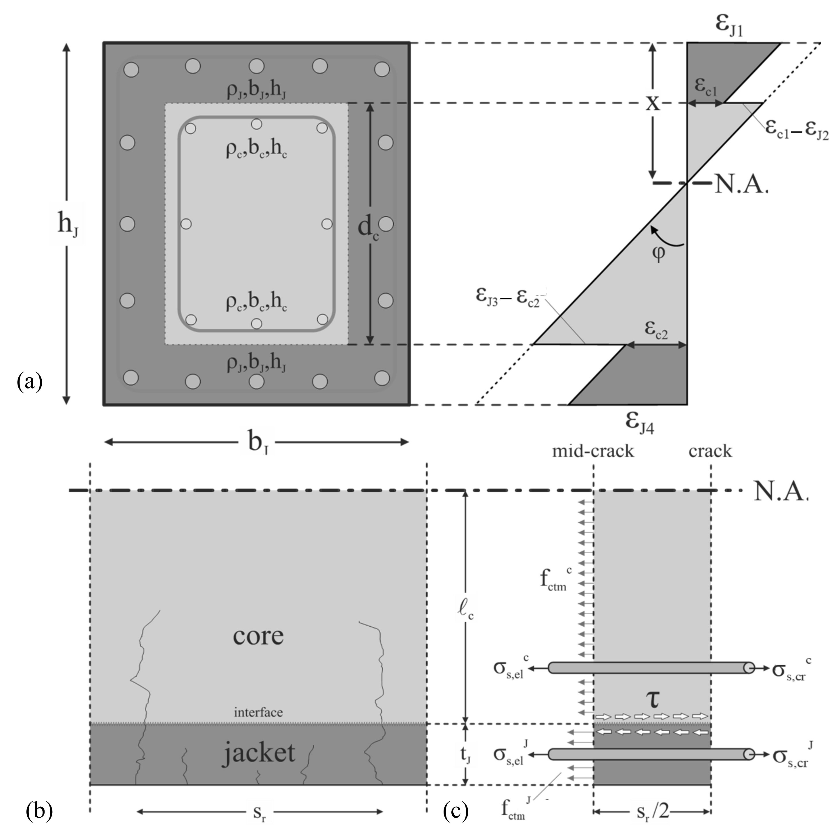
2. Overview of the Analytical Model for the Behaviour of Jacketed R/C Members

The analytical model for predicting the flexural response of existing R/C members strengthened with concrete jacketing under monotonic and cyclic loading conditions introduces a degree of freedom allowing the relative slip at the interface between the existing member and the jacket [6,7,8]. Slip along the member length is attributed to the difference in normal strains at the contact interfaces (Figure 1). For flexural analysis, the cross-section is divided into three layers that bend with the same curvature, φ (Figure 1). The two external layers represent the contribution of the jacket, whereas the internal one represents both the core (existing cross-section) and the web of the jacket shell. The slip at the interface mobilizes the shear transfer mechanisms such as aggregate interlock, the friction generated by clamping action of the bars, and dowel action provided by the ties/hoops of the jacket and by the dowels placed at the interface between the core and the jacket in cases where such a connection measure is taken.
Shear transfer at the interface between the existing member and the jacket takes place between half-crack intervals along the length of the jacketed member, as commonly considered in the bond analysis. At the initial stages of loading, cracks form only at the external layers (i.e., the jacket) increasing in number with increasing load, up to crack stabilization (Figure 1).
Shear stress demand at the interfaces, τd,i, is determined by examining the cross-section along the height and along a member length equal to the distance between successive cracks (Figure 1). The layer force resultant ΣFi (sum of concrete and steel forces at each layer), for the externally applied axial load, Next (considered to be applied to the jacketed section), is used to calculate the vertical shear stress demand in the member, τd,i. With the assumption that the shear flow reversal takes place at a length equal to sr/2 (where sr is the crack spacing), the average stress demand τd,i is equal to:
τ d , i = Σ F i 0.5   s r   b J
where ΣFi is the layer force resultant and bJ is the width of the jacketed cross section; sr is the crack spacing (distance between adjacent cracks assumed to be constant), defined as follows [7]:
s r = 0.64   b J   c f ctm , c n c   D b , c   f b , c + n J   D b , J   f b , J
where bJ is the width of the jacketed cross-section, ℓc is the depth of the tension zone in the core of the composite cross-section, fctm,c is the tensile strength of core concrete, nc, nJ are the number of bars in the tension steel layer of the core and the jacket, respectively, Db,c, Db,J are the bar diameter of the core and jacket longitudinal reinforcement, respectively, and fb,c, fb,J are the average bond stress of the core and the jacket reinforcement layer, respectively.
The model considers that slip at the sliding plane mobilizes the shear transfer mechanisms such as aggregate interlock, friction owing to clamping action, and dowel action of both the stirrup legs of the jacket and any dowels that may be placed at the interface (whenever this is introduced as an additional connection measure). Indeed, Equation (2) defines the vertical shear stress demand of the member which following basic mechanics is taken equal to the horizontal shear stress mobilized along the interface for a given slip magnitude. The shear resistance at the interface will be provided by the frictional resistance at the interface and the dowel resistance. The legs of the stirrups of the jacket and any additional dowels used as connection measures will be used to calculate the shear resistance of the dowels. Details of these are provided in references [7,8].
The aim of the calculation algorithm at each loading step is twofold; simultaneously establishing equilibrium between the shear stress capacity and demand at the interfaces for relative slip, s, and force equilibrium at the cross-section. An iterative procedure is followed and equilibrium is established until convergence is achieved. Due to the complexity of the proposed solution algorithm, a computer program had to be developed [8], using the fibre approach. The program was utilised herein for performing the analyses carried out in the frame of the parametric study (Section 4). The derived moment–curvature response curves were further processed to obtain the necessary response parameters for the definition of the monolithicity factors utilised herein. It is noted that no preloading is assumed in the analysis of the jacket (see further discussion in Section 4).

3. Monolithicity Factors Derived from Experimental Results

3.1. Experimental Database

Despite the popularity of R/C jacketing as an intervention method for the seismic retrofitting of existing substandard columns, the pertinent experimental studies carried out so far are fairly limited. In an effort to gather the bulk of the existing information on the behaviour of R/C jacketed columns, an experimental database was created which includes 44 specimens from 11 experimental studies. The database includes specimens where various connection measures were taken between the existing member and the jacket, whereas the jacket construction was done using either shotcrete or cast-in-place concrete. The range of parameters for the specimens included in the database is shown in Table 1 (an explanation of symbols is given in Appendix A).
After processing the experimental envelope curves [10], experimental values of the monolithicity factors were defined; they are summarised in Table 2.
The various monolithicity factors reported in Table 2 are:
(i) Factors that refer to deformation quantities such as the chord rotations at yield and ultimate, which are defined as:
- Chord rotation at yielding:
K θ y = θ y , J θ y , M
- Chord rotation at ultimate:
K θ u = θ u , J θ u , M
(ii) Strength-related monolithicity factors:
- Shear strength:
K v = V J , max V M , max
- Yield moment:
K M y = M y , J M y , M
(iii) The stiffness monolithicity factor (stiffness at yielding):
K k = K y , J K y , M
where the subscripts J and M correspond to the composite (jacketed) cross-section and the identical monolithic cross-section, θy, θu are the rotations at yield and ultimate, My is the yield moment, and Kk is the secant flexural stiffness at yield.
It is noted that all Ki,M quantities are experimental values since an analytical estimation would have introduced an additional important source of uncertainty. Specifically, only those tests from the database (37 out of the 44) for which a monolithically cast composite (core + jacket) specimen was available were used. It is also worth pointing out that another significant uncertainty is the definition of ‘yield point’ which is necessary for defining factors such as Kθ,y and KM,y. The values reported in Table 2 are those resulting from bilinearising the envelopes of the experimental hysteresis loops using the commonly adopted equal energy absorption approach; another (more convenient and hence often used) approach was also explored, i.e., drawing a bilinear (no hardening) envelope passing from the point corresponding to the development of 80% of the maximum measured strength and terminating at the point where the strength has dropped to 80% of the strength (i.e., failure defined at 20% drop in strength, which was also used in the equal energy absorption procedure). The differences in the estimated KM,y were found [10] to be of the order of only 10%, but differences in Kθ,y were much more significant (up to 250%), underlining the sensitivity of ‘yield deformation’ definition to the procedure used.

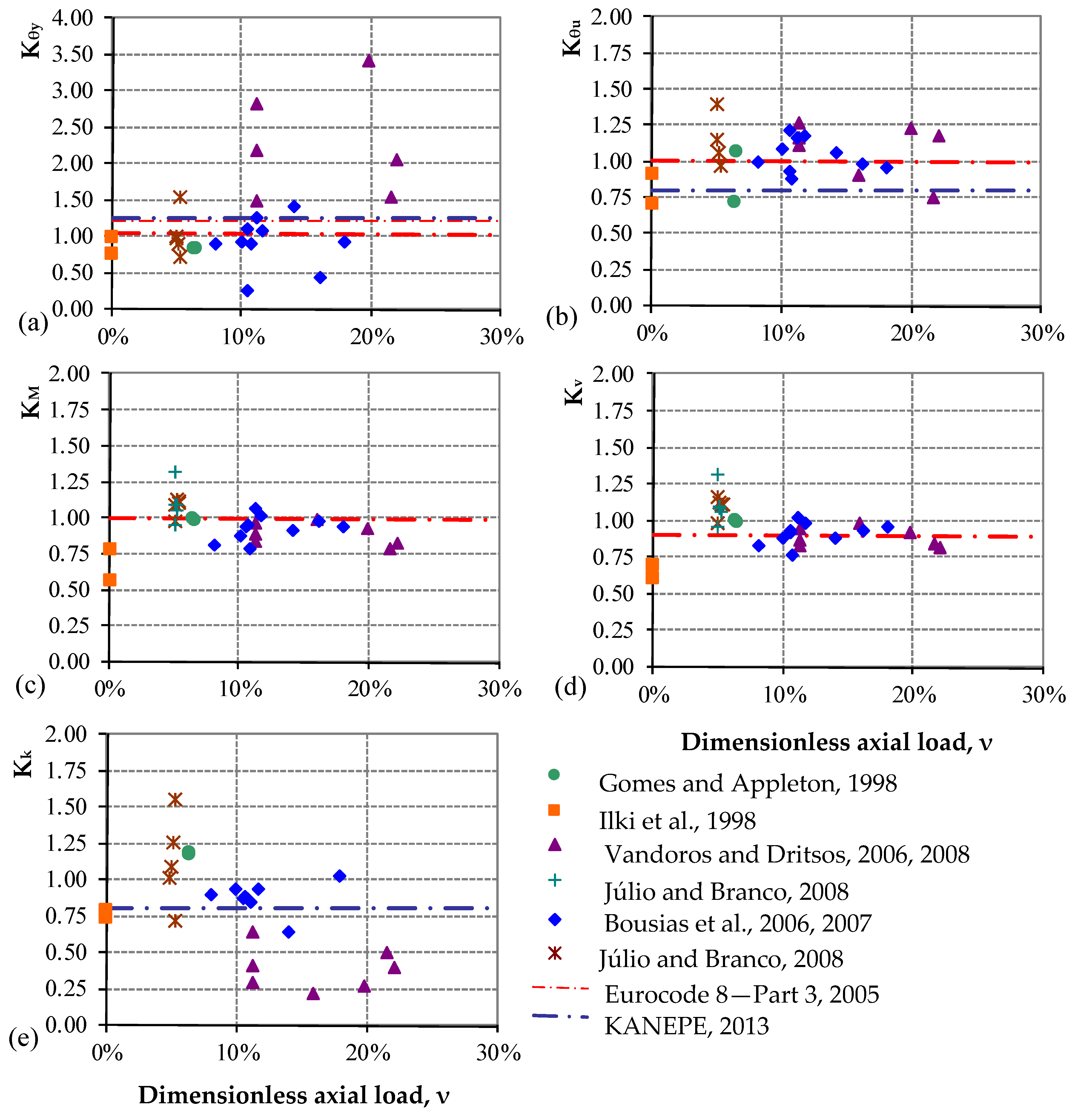
3.2. Comparison between Experimental Values of the Monolithicity Factors and Code Values

The monolithicity factors adopted by the aforementioned codes are compared with the experimental values for monolithicity factors in Figure 2. The red and blue coloured horizontal dashed lines correspond to the monolithicity factors prescribed in EC8—Part 3 [4] and KANEPE [5], respectively. It is clear that there is large dispersion in the case of monolithicity factors Kθy, Kθu and Kk. This tendency can be, at least partly, attributed to the limited range of parameters covered in the experimental database, and also to the uncertainty involved in defining some of these factors (e.g., the sensitivity of Kθy to the definition of a ‘yield point’). One should also note that deformation and stiffness values are difficult to measure experimentally and ‘ultimate’ conditions are not defined in a uniform way in all tests.

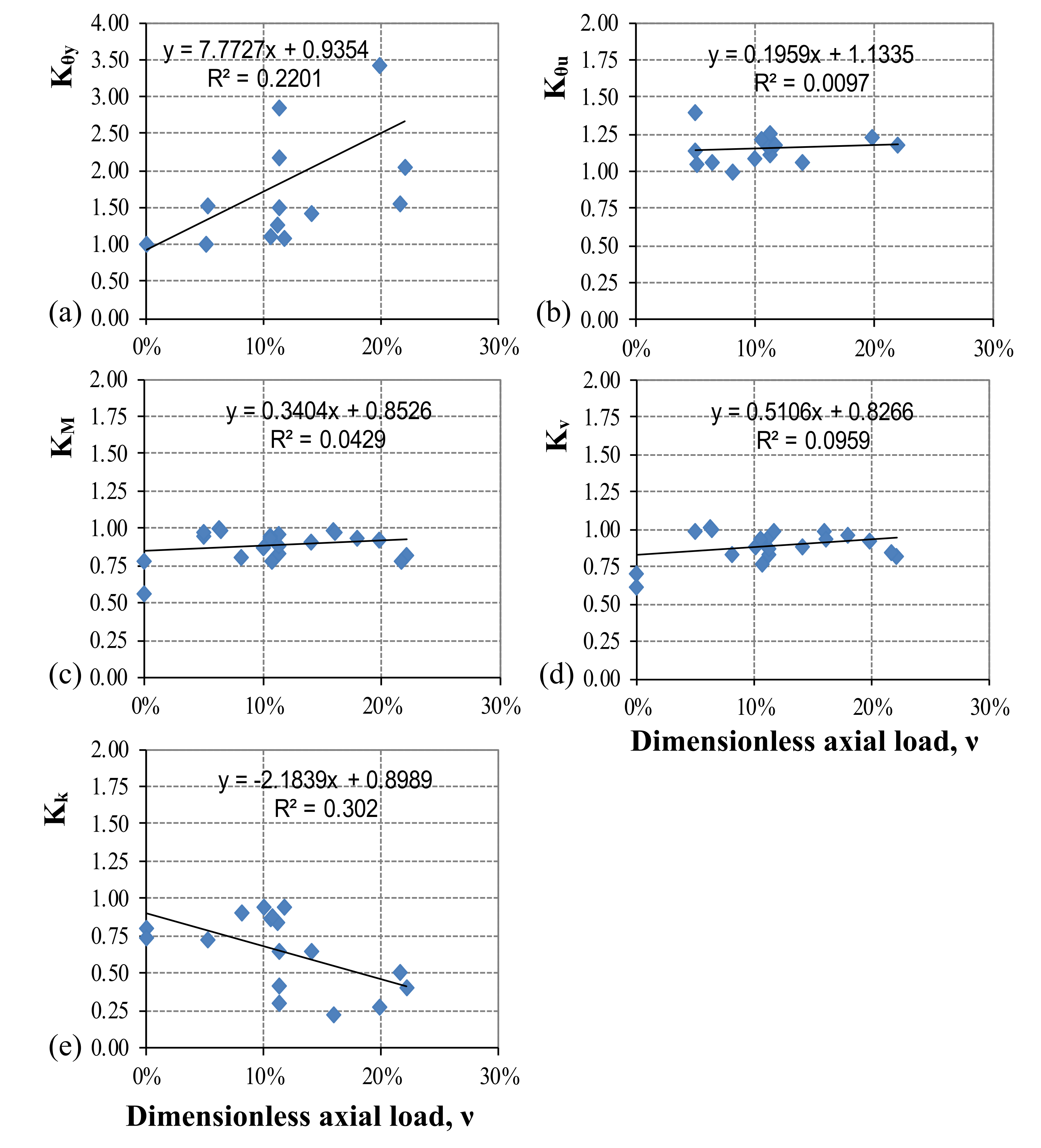
3.3. Expressions Derived by Regression of Experimental Data

The values of the monolithicity factors presented in Table 2 were utilised for the derivation of design expressions. The values with no physical meaning such as Kθy < 1, Kθu < 1, KMy > 1, KV > 1, Kk > 1 were excluded from the data used in the regression analysis. The expressions were determined by best fit linear equations (Figure 3) and are the following:
Kθy = 0.94 + 0.77·ν
Kθu = 1.13 + 0.20·ν
KMy = 0.85 + 0.34·ν
KV = 0.83 + 0.51·ν
Kk = 0.90 − 2.18·ν
where ν should be taken as positive for compression loading.

4. Monolithicity Factors Derived from Numerical Studies

An extensive parametric investigation was performed using the model described in Section 2, for 250 mm, 300 mm, 400 mm, 500 mm square and 200 mm × 400 mm, 250 mm × 500 mm rectangular core cross-sections. Reinforcement detailing and material properties were representative of the construction practice shaped by older generation codes, specifically those of the 1960s and 1970s. The percentage of the longitudinal reinforcement was ρc = 1% and open ties ∅6/300 were utilised. St I (mean yield strength fy ≈ 250 MPa) and St III (mean fy ≈ 480 MPa) were the steel grades used for smooth and ribbed longitudinal reinforcement, respectively, whereas St I was used for ties. For the core of the jacketed cross-section, the concrete grades selected were B160, B225 (older generation of codes, grade based on average cube strength in kg/cm2), C20/25 (close to B300) and C30/37. The thickness of the jacket assumed values equal to 75, 100 and 125 mm. The percentage of the longitudinal reinforcement of the jacket (ρJ = AJ/(bJhJ − bchc)) ranged between 1% and 4%, whereas the ties placed were ∅8/100. The concrete grades selected for the jacket were C20/25, C25/30, C30/37 and C50/60, whereas B500C (characteristic yield strength fyk = 500 MPa) ribbed bars were used for the longitudinal and transverse reinforcement. Another parameter of investigation was the dimensionless axial load, ν = N/(bchcfc,c + (bJhJ − bchc)·fc,J), which was considered to be applied only to the core cross-section [19] and ranged between 0 and 40%. All the groups defined for the needs of the parametric study are shown in Table A1 of Appendix B.
The analytical model (Section 2) was utilised for the derivation of moment–curvature (M–φ) curves for monotonic loading with or without the presence of slip at the interface between the existing cross-section (core) and the jacket. The response curves were bi-linearised using BILIN [20], an in-house developed software package that adopts the equal energy absorption concept for bi-linearising a force–deformation curve. The curvature values at yielding and ultimate were transformed to rotation values according to the procedure described in [21].
Processing the results of the extensive parametric study (768 cases), discrete values for the monolithicity factors related to strength, stiffness and deformation capacity indices were defined. These values were used for the derivation of the design expressions for the various factors that appear in Table 3, Table 4, Table 5 and Table 6. For all cases, the concrete compressive strength in the jacket was considered higher than 30 MPa. Moreover, the longitudinal reinforcement of the jacket ρJ = AsJ,tot/(bJhJ − bchc) was considered to take values up to 2% which is consistent with the ratios used in the experimental studies but does not necessarily represent design practice in all countries.
As seen in Table 3, Table 4, Table 5 and Table 6, the design expressions for the various monolithicity factors are simple functions of the normalised axial loading only, hence easy to implement. Nevertheless, the expressions are generally different for different thicknesses of the jacket and the concrete compressive strength of the core (existing cross-section). A single expression for each factor can be derived, but the associated scatter substantially increases. Since in actual design the factors will be applied in an automated form (use of software) it is deemed that they can be easily differentiated according to the aforementioned geometric and strength parameters. For hand calculations, one expression for each factor is preferred, as discussed in the next section (Section 4.1).

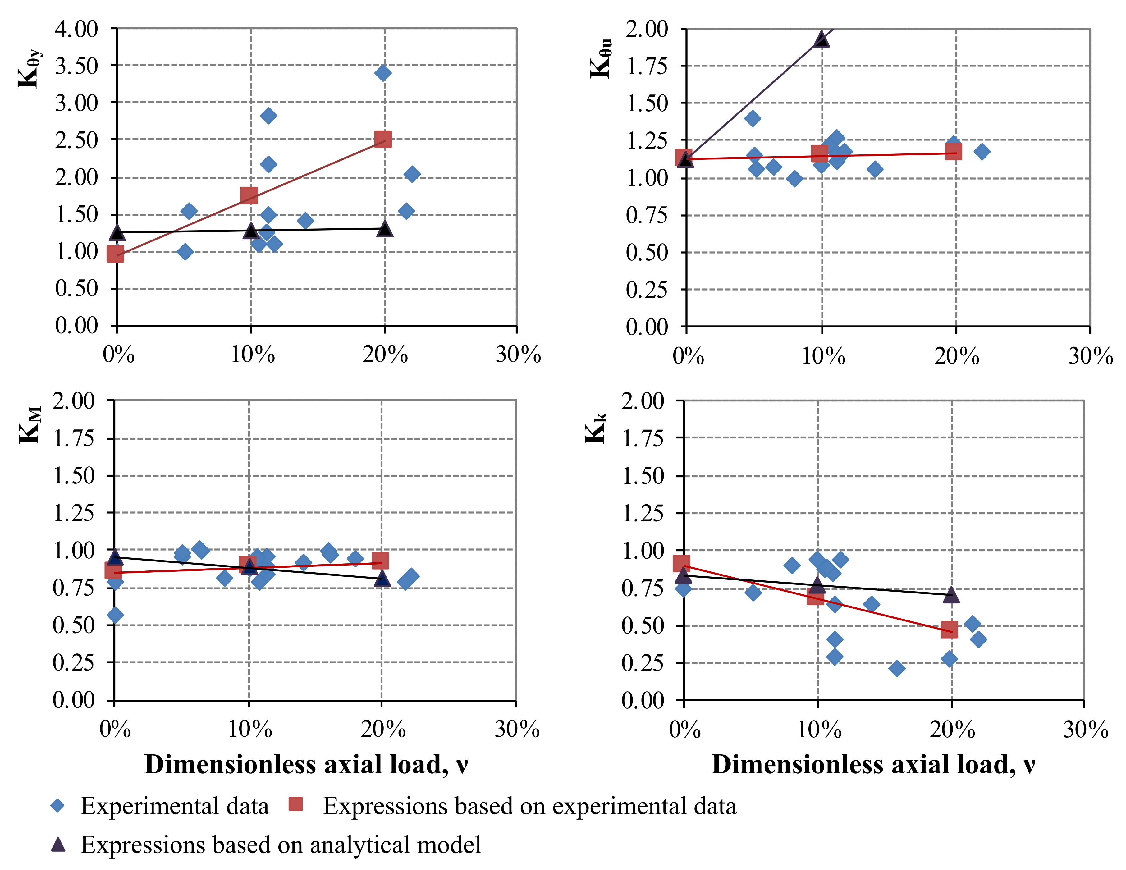
4.1. Comparison between Numerically and Experimentally Derived Expressions

The dark blue coloured lines that appear in Figure 4 correspond to the following proposed design expressions (refer to Table 3, Table 4, Table 5 and Table 6):
KM = 0.96 − 0.74·ν
Kk = 0.83 − 0.64·ν
Kθy = 1.26 + 0.28·ν
Kθu = 1.00 + 7.20·ν
The expressions were derived for tJ = 75 mm, fc,o > 20 MPa and ρJ = 1%, which is the most representative scenario considering the range of parameters of the experimental database (Table 1). Moreover, the red coloured lines that appear on the same graph follow the expressions derived based on the experimental data (Section 3.2).

5. Conclusions and Finally Adopted Values

It is clear that there is a very significant dispersion in the monolithicity factors estimated on the basis of test results. The analytical values are more consistent but are not always conservative when compared with test-derived values. Based on the information shown in Figure 3, Kθu values resulting from the analytical model developed by Thermou et al. [8] overestimate the corresponding experimental values; this is mainly attributed to the assumptions made to derive the relevant rotations from the curvature values provided by the analytical model, a step which is necessary because the Code provisions are in terms of (chord) rotations. It seems that slip at ultimate reaches much higher values than the ones measured experimentally. Hence, for this particular case, it is safer to consider Kθu equal to unity, and this is the value adopted in both the current and the new Code.
Following a number of exchanges within the Project Team 3 (the team that prepared the draft of the new Eurocode 8—Part 3) and SC8 (the CEN subcommittee responsible for the development of Eurocode 8), the following expressions (functions of ν) were finally adopted:
(i) For the yield moment:
K My = 0.96 0.74 ν
(ii) For the yield rotation:
K θ y = 1.05   θ y   when   special   measures   to   prevent   interface   slip   are   applied 1.26 + 0.28   ν   θ y   for   all   other   cases
where ν is the normalised axial loading N/(bchcfc,c + (bjhj − bchc)fc,j) acting on the jacketed element.
The adopted constant factor for shear strength is KV = 0.9, which is the same as in the current code and is consistent with the values estimated from tests (Table 2). The expression for stiffness Kk = 0.83 − 0.64·ν is typically not required (as stiffness is calculated from the corresponding My and θy), while the ultimate rotation θu is conservatively taken the same as that of the corresponding monolithic section.
Finally, it should be noted that all previous expressions are based on mean values of the estimated monolithicity factors (the limited data available cannot be used to define reliable characteristic values). It is emphasised that these factors are ratios of quantities, hence there is no need for safety factors to be applied to them; the safety factors will be applied to the strength and/or deformation quantities in the pertinent verifications. Moreover, Eurocode 8—Part 3 uses mean values for all verifications involving existing or strengthened members; in fact, in the new Code it is expected that this will also be extended to the ‘new’ (added) members, i.e., all verifications will be based on mean values.

Author Contributions

Conceptualization, G.E.T. and A.J.K.; methodology, G.E.T. and A.J.K.; investigation, G.E.T. and A.J.K.; data curation, G.E.T.; writing—original draft, A.J.K.; writing—reviewing and editing, G.E.T. and A.J.K.; supervision and funding acquisition, A.J.K. All authors have read and agreed to the published version of the manuscript.

Funding

This research was partially funded by the Earthquake Planning and Protection Organization of Greece through the project “Investigation of the behaviour of old reinforced concrete columns strengthened with R/C jackets” (February 2010–June 2011), PI: A. Kappos.

Institutional Review Board Statement

Not applicable.

Informed Consent Statement

Not applicable.

Data Availability Statement

The experimental data used as part of this study is summarised in reference [10] and is available from the authors upon reasonable request.

Acknowledgments

This project has received partial funding from the Earthquake Planning and Protection Organization of Greece. The contribution of Vassilis Papanicolaou, at the Aristotle University of Thessaloniki (Greece), to the development of the model and software used for the numerical part of this study is gratefully acknowledged.

Conflicts of Interest

The authors declare no conflict of interest.

Appendix A. Symbols Used in the Experimental Database

bc; bJ:width of the existing and the jacketed cross section
Db,c; Db,J:bar diameter of the core and the jacket longitudinal reinforcement, respectively
Dbs,c; Dbs,J:bar diameter of the stirrups of the core and the jacket, respectively
dc; dJ:depth of the existing and the jacketed cross section, respectively
fc,c; fc,J:core and jacket concrete cylinder uniaxial compressive strength, respectively
fy,c; fy,J:yield strength of the longitudinal reinforcement of the core and jacket, respectively
fyw,c; fyw,J:yield strength of the transverse reinforcement of the core and jacket, respectively
hc; hJ:height of the existing and the jacketed cross section, respectively
Ls:shear span length
nc,mid; nJ,mid:total number of web longitudinal reinforcement bars of the core and the jacket, respectively
nc; nJ:total number of top and bottom longitudinal reinforcement bars of the core and the jacket, respectively
sc; sJ:stirrup distance in the existing and jacketed cross section, respectively
Greek symbols:
ν:dimensionless axial load % estimated as: N/(bchcfc,c+ (bJhJ−bchc)·fc,J)
ρc:longitudinal reinforcement ratio of the existing cross section defined as Asc,tot/(bchc), where Asc,tot = (nc + nc,mid)Db,c2/4
ρJ:longitudinal reinforcement ratio of the jacketed cross section defined as AsJ,tot/(bJhJ − bchc), where AsJ,tot = (nJ + nJ,mid)Db,J2/4
ρwc; ρwJ:volumetric ratio of stirrups of the existing and the jacketed cross section, respectively

Appendix B. Data for Parametric Study

Table A1. Groups of parametric study.
ParametersGroup 1 (250 mm × 250 mm)Group 2 (250 mm × 250 mm)Group 3 (300 mm × 300 mm)Group 4 (300 mm × 300 mm)Group 5 (300 mm × 300 mm)Group 6 (400 mm × 400 mm)
1a1b1c2a2b2c3a3b3c4a4b4c5a5b5c6a6b6c
Jacket Thickness75 mm
100 mm
125 mm
Core ConcreteB160 (10 MPa)
B225 (16 MPa)
C20/25 (28 MPa)
C30/37 (38 MPa)
Core steelStI
StI + StIII
Jacket ConcreteC20/25 (28 MPa)
C25/30 (33 MPa)
C30/37 (38 MPa)
C50/60 (58 MPa)
Jacket SteelB500C
ρJ1–4%
ν (%)10–40
ParametersGroup 7 (400 mm × 400 mm)Group 8 (500 mm × 500 mm)Group 9 (500 mm × 500 mm)Group 10 (200 mm × 400 mm)Group 11 (200 mm × 400 mm)Group 12 (200 mm × 400 mm)
7a7b7c8a8b8c9a9b9c10a10b10c11a11b11c12a12b12c
Jacket Thickness75 mm
100 mm
125 mm
Core ConcreteB160 (10 MPa)
B225 (16 MPa)
C20/25 (28 MPa)
C30/37 (38 MPa)
Core steelStI
StIII
Jacket ConcreteC20/25 (28 MPa)
C25/30 (33 MPa)
C30/37 (38 MPa)
C50/60 (58 MPa)
Jacket SteelB500C
ρJ1–4%
ν (%)10–40
ParametersGroup 13 (200 mm × 400 mm)Group 14 (250 mm × 500 mm)Group 15 (250 mm × 500 mm)Group 16 (250 mm × 400 mm)
13a13b13c14a14b14c15a15b15c16a16b16c
Jacket Thickness75 mm
100 mm
125 mm
Core ConcreteB160 (10 MPa)
B225 (16 MPa)
C20/25 (28 MPa)
C30/37 (38 MPa)
Core steelStI
StIII
Jacket ConcreteC20/25 (28 MPa)
C25/30 (33 MPa)
C30/37 (38 MPa)
C50/60 (58 MPa)
Jacket SteelB500C
ρJ1–4%
ν (%)10–40

References

  1. Rodriguez, M.; Park, R. Seismic load tests on reinforced concrete columns strengthened by jacketing. ACI Struct. J. 1994, 91, 150–159. [Google Scholar]
  2. Vandoros, K.G.; Dritsos, S.E. Interface treatment in shotcrete jacketing of reinforced concrete columns to improve seismic performance. J. Struct. Eng. Mech. 2006, 23, 43–61. [Google Scholar] [CrossRef]
  3. Bousias, S.; Biskinis, D.; Fardis, M.N.; Spathis, A.-L. Strength, stiffness, and cyclic deformation capacity of the concrete jacketed members. ACI Struct. J. 2007, 104, 521–531. [Google Scholar]
  4. CEN [Comité Européen de Normalisation]. Eurocode 8, Design of Structures for Earthquake Resistance, Part 3, Assessment and Retrofitting of Buildings (EN1998-3); European Committee for Standardization: Brussels, Belgium, 2005. [Google Scholar]
  5. EPPO [Earthquake Planning and Protection Organization of Greece]. Greek Code for Interventions (KANEPE); EPPO: Athens, Greece, 2013. [Google Scholar]
  6. Thermou, G.E.; Papanikolaou, V.K.; Kappos, A.J. Cyclic Response of R/C jacketed columns including modelling of the interface behaviour. In Proceedings of the 15th World Conference on Earthquake Engineering, Lisbon, Portugal, 24–28 September 2012. Paper No. 2855. [Google Scholar]
  7. Thermou, G.E.; Pantazopoulou, S.J.; Elnashai, A.S. Flexural behavior of brittle RC members rehabilitated with concrete jacketing. ASCE J. Struct. Eng. 2007, 133, 1373–1384. [Google Scholar] [CrossRef]
  8. Thermou, G.E.; Papanikolaou, V.K.; Kappos, A.J. Flexural behaviour of reinforced concrete jacketed members under reversed cyclic loading. Eng. Struct. 2014, 76, 270–282. [Google Scholar] [CrossRef]
  9. Minafò, G.; Di Trapani, F.; Amato, G. Strength and ductility of RC jacketed columns: A simplified analytical Method. Eng. Struct. 2016, 122, 184–195. [Google Scholar] [CrossRef] [Green Version]
  10. Kappos, A.J.; Thermou, G.E.; Papanikolaou, V.K. Investigation of the behaviour of old type R/C columns strengthened with R/C jackets. In Final Project Report; Earthquake Planning and Protection Organization: Athens, Greece, 2012. [Google Scholar]
  11. Gomes, A.M.; Appleton, J. Repair and strengthening of R.C. elements under cyclic loading. In Proceedings of the 11th European Conference on Earthquake Engineering, Paris, France, 6–11 September 1998. [Google Scholar]
  12. Ilki, A.; Darilmaz, K.; Bakan, I.; Zorbozan, M.; Yuksel, E.; Haruhan, S.; Karadogan, F. Jacketing of prefabricated columns. In Proceedings of the 2nd Japan-Turkey Workshop on Earthquake Engineering, Istanbul, Turkey, February 1998; pp. 329–336. [Google Scholar]
  13. Vandoros, K.G.; Dritsos, S.E. Axial preloading effects when reinforced concrete columns are strengthened by concrete. Prog. Struct. Eng. Mater. J. 2006, 8, 79–92. [Google Scholar] [CrossRef]
  14. Vandoros, K.G.; Dritsos, S.E. Concrete jacket construction detail effectiveness when strengthening R/C columns. Constr. Build. Mater. 2008, 22, 264–276. [Google Scholar] [CrossRef]
  15. Júlio, E.N.B.S.; Branco, F.A.B.; Silva, V.D. Reinforced concrete jacketing—Interface influence on monotonic loading response. ACI Struct. J. 2005, 102, 252–257. [Google Scholar]
  16. Bousias, S.; Spathis, A.-L.; Fardis, M.N. Concrete or FRP jacketing of columns with lap splices for seismic rehabilitation. J. Adv. Concr. Technol. 2006, 4, 431–444. [Google Scholar] [CrossRef] [Green Version]
  17. Bousias, S.; Spathis, A.-L.; Fardis, M.N. Seismic retrofitting of columns with lap-spliced smooth bars through FRP or Concrete Jackets. J. Earthq. Eng. 2007, 11, 653–674. [Google Scholar] [CrossRef]
  18. Júlio, E.N.B.S.; Branco, F.A.B. Reinforced concrete jacketing—Interface influence on cyclic loading response. ACI Struct. J. 2008, 105, 417–477. [Google Scholar]
  19. Papanikolaou, V.K.; Stefanidou, S.P.; Kappos, A.J. The Effect of Preloading on the Strength of Jacketed R/C Columns. Constrn. Build. Mater. 2013, 38, 54–63. [Google Scholar] [CrossRef] [Green Version]
  20. Panagopoulos, G.; Kappos, A.J. BILIN, Software for the Bilinear Approximation of Force—Deformation Response Curves; Laboratory of Reinforced Concrete and Masonry Structures, Aristotle University of Thessaloniki: Thessaloniki, Greece, 2008. [Google Scholar]
  21. Thermou, G.E.; Papanikolaou, V.K.; Kappos, A.J. Monolithicity factors for the design of RC columns strengthened with RC jackets. In Proceedings of the 2nd European Conference on Earthquake Engineering and Seismology, Istanbul, Turkey, 24–29 August 2014. Paper No. 776. [Google Scholar]
Figure 1. (a) Strain profile of the jacketed cross section, (b) crack spacing, sr, and (c) free body equilibrium in the tension zone of the composite section.
Buildings 12 00055 g001
Figure 2. Comparison between the experimental values of monolithicity factors and the prescribed values of EC8—Part 3 and the Greek KANEPE for (a) Kθy, (b) Kθu, (c) KM, (d) Kv, (e) Kk.
Buildings 12 00055 g002
Figure 3. Expressions derived by regression of experimental data for (a) Kθy, (b) Kθu, (c) KM, (d) Kv, (e) Kk.
Buildings 12 00055 g003
Figure 4. Comparison between the experimental values of the monolithicity factors and the ones based on the proposed expressions and the expressions derived from experimental data.
Buildings 12 00055 g004
Table 1. Range of parameters of the experimental database 1.
Existing MemberJacket
bc (mm)200–350bJ (mm)260–550
hc (mm)200–500hJ (mm)260–650
Db,c (mm)10–20tJ (mm)30–100
ρc (%)0.81–2.05Db,J (mm)10–20
Dbs,c (mm)6–8ρJ (%)0.75–1.64
sc (mm)50–265Dbs,J (mm)6–10
ρwc (%)0.12–0.57sJ (mm)50–100
fc,c (MPa)22.9–58.2ρwJ (%)0.20–0.79
fy,c (MPa)313–550fc,J (MPa)7–68.7
fyw,c (MPa)350–520fy,J (MPa)400–520
Ls/hc3.2–11.7fyw,J (MPa)330–599
Lap (db,c)15–45Ls/hJ2.5–7.0
Ls (mm)1000–3500
ν (%)0–23
1 For list of symbols used in the table see Appendix A.
Table 2. Experimental values of monolithicity factors.
ReferenceKθyKθuKMyKvKk
Gomes and Appleton [11]0.840.73, 1.070.99, 1.000.99, 1.001.18, 1.20
Ilki et al. [12]0.77, 1.000.72, 0.920.57, 0.790.62, 0.700.74, 0.79
Vandoros and Dritsos [2,13,14]1.49–4.540.75–1.260.78–0.990.82–0.980.22–0.64
Júlio et al. [15]--0.96–1.32--
Bousias et al. [3,16,17]0.26–1.410.88–1.210.79–1.060.76–1.020.64–3.65
Júlio & Branco [18]0.71–1.530.97–1.410.98–1.130.98–1.170.72–1.56
min/max0.26/4.540.72/1.400.57/1.320.62/1.170.22/3.65
Mean *1.091.030.960.931.06
* Specimens with Kθy > 2.5 were excluded from the estimation of the mean.
Table 3. Expressions for strength-related monolithicity factor, KMy.
Jacket ThicknessCore Concrete StrengthJacket Long. Reinf.KMy
tJ = 75 mmfc,o < 20 MPaρJ = 1%0.87 − 0.81·ν
ρJ = 2%0.68 − 0.46·ν
fc,o > 20 MPaρJ = 1%0.96 − 0.74·ν
ρJ = 2%
tJ = 125 mmfc,o < 20 MPaρJ = 1%0.70 − 0.78·ν
ρJ = 2%0.55 − 0.49·ν
Table 4. Expressions for stiffness monolithicity factor, Kk.
Jacket ThicknessCore Concrete StrengthJacket Long. Reinf.Kk
tJ = 75 mmfc,o < 20 MPaρJ = 1%0.84 − 0.95·ν
ρJ = 2%0.69 − 0.50·ν
fc,o > 20 MPaρJ = 1%0.83 − 0.64·ν
ρJ = 2%
tJ = 125 mmfc,o < 20 MPaρJ = 1%0.57 − 0.70·ν
ρJ = 2%0.46 − 0.33·ν
Table 5. Expressions for chord rotations at yield, Kθy.
Jacket ThicknessCore Concrete StrengthJacket Long. Reinf.Kθy
tJ = 75 mmfc,o < 20 MPaρJ = 1%1.17 + 0.63·ν
ρJ = 2%1.16
fc,o > 20 MPaρJ = 1%1.26 + 0.28·ν
ρJ = 2%1.12 + 0.34·ν
tJ = 125 mmfc,o < 20 MPaρJ = 1%1.50
ρJ = 2%1.62 − 1.09·ν
Table 6. Expressions for chord rotations at ultimate, Kθu.
Jacket ThicknessCore Concrete StrengthJacket Long. Reinf.Kθu
tJ = 75 mmfc,o < 20 MPaρJ = 1%1.00 + 7.20·ν
ρJ = 2%
fc,o > 20 MPaρJ = 1%
ρJ = 2%1.13 + 8.01·ν
tJ = 125 mmfc,o < 20 MPaρJ = 1%1.24 + 8.24·ν
ρJ = 2%1.48 + 7.77·ν
Publisher’s Note: MDPI stays neutral with regard to jurisdictional claims in published maps and institutional affiliations.

