
Ductility of Concrete Beams Reinforced with FRP Rebars


Faculty of Civil Engineering, University of Zagreb, 10000 Zagreb, Croatia
*
Author to whom correspondence should be addressed.
Buildings 2021, 11(9), 424; https://doi.org/10.3390/buildings11090424
Submission received: 30 August 2021
/
Revised: 13 September 2021
/
Accepted: 17 September 2021
/
Published: 21 September 2021
(This article belongs to the Collection The Methods, Tools and Techniques for the Preservation of Existing Structures)
Abstract
:Concrete beams reinforced with FRP rebars have greater durability than standard steel reinforced elements. The main disadvantage of using FRP rebars is the low ductility of elements which may be unacceptable in certain situations. There are several different ways of increasing the ductility of concrete elements, which are analyzed in this paper. They are compared based on efficiency, influence on durability and ease of construction. Less analyzed and tested methods are given more attention to try and expand the current knowledge and possibilities. For methods that lack experimental data, theoretical analysis is undertaken to assess the possible influence of that method on the increase in ductility. Ductility was obtained by calculating bending moment–curvature diagrams of cross sections for different reinforcement layouts. One method that lacks experimental data is confining the compressive area of beams with tensile FRP reinforcement. Theoretical analysis showed that confining the compressive area of concrete can significantly increase the ductility and bending capacity of beams. Since experimental data of beams reinforced with FRP rebars in tension and confined compressive area is sparse, some suggestions on the possible test setups are given to validate this theoretical analysis. Concrete beams reinforced with FRP can be detailed in such a way that they have sufficient ductility, but additional experimental research is needed.
1. Introduction
Reinforced concrete is a widely used construction material because of its many advantages. On the other hand, some disadvantages such as poor durability limit its use. Durability issues are mainly caused by using steel reinforcement. They can be avoided by using fiber reinforced polymer (FRP) instead of steel. Fibers in FRP are usually made of carbon or glass, but aramid, basalt and flax fibers may also be used. Polymer matrix is used to connect the multiple fibers in one solid bar, most commonly epoxy or polypropylene are used. Fibers ensure tensile capacity, while matrix ensures the shape of the bar and its shear capacity [1].
Although FRP does not corrode in the same manner as steel, prolonged water exposure, high temperatures and high long term stress can cause durability issues [2,3,4]. An alkali concrete environment can also cause durability issues for some types of fiber, but rebars are usually made of alkali resistant materials. FRP has several disadvantages compared to steel, most notably for structural applications, being lack of ductility and complicated bending of bars [5]. Although bending is possible during production, the strength of bent bars is lower and construction options are limited compared with steel. FRP bars also have poor performance when loaded in compression [6] due to stability issues.
Ductility is a very important property of structures in seismically active areas [7], even more so than their strength. According to [8] ductility is the most important characteristic of a structure in seismic areas. In most cases a combination of load bearing capacity and ductility is important, rather than just one of them. Although ductility enables design of safer structures, it complicates calculations, and design values of internal forces are not easily obtained, as seen in [9]. For steel reinforced elements, ductility is dependent on a few things. On a structural level, capacity design is very important because it aims to avoid non-ductile types of failure such as shear. This is implemented in the current Croatian (and European) design code HRN EN 1998-1 [10] as well as in most other codes in the world. On an elemental level, detailing provisions can significantly influence the behavior of elements. The amount of compressive and confinement reinforcement can improve the behavior of elements [11], while increasing the tensile reinforcement can decrease their ductility. Elements that fail by crushing of concrete before the steel reinforcement yields have a very low ductility. This is the case for beams with a large amount of tensile reinforcement and such elements are called over-reinforced.
Research on the ductility of elements with FRP rebars is limited. Instead, more attention is given to the use of FRP for structural repair and strengthening [12] than to its use in new structures. Ductility of both strengthened and new structures is discussed in this paper, but the focus is on new structures. Most common methods for both existing and new structures are mentioned and analyzed in the following section. Some methods used in steel reinforced elements are analyzed because they relate well to FRP reinforced elements and provide a crucial insight into the behavior of concrete elements.
2. Methods of Increasing the Ductility of Concrete Elements
As mentioned earlier, ductility of elements can be achieved by appropriate detailing, most commonly, concrete is confined to ensure the ductility.
Confinement of concrete increases the ductility and strength of concrete as a material [13], which in turn causes an increase in element ductility. Due to a low ductility of over-reinforced beams, several experiments were conducted in the 1960s [14,15] where the compression area of over-reinforced beams was confined. Steel reinforcement was used in those studies, and it was shown that adding spiral or rectangular stirrups in the compressive area of the beam increased its ductility significantly. In recent years this was confirmed for steel reinforced elements for various confinement layouts and methods. Usually, over-reinforced sections and/or high concrete strength were used.
In this paper, all transverse reinforcement will be called stirrups regardless of their use, for simplicity. Alternatives to stirrups are possible for confinement of the compression area, such as adding steel plates with dowels as in [16,17]. This method increases the ductility, but also the load bearing capacity and stiffness. In addition, cracks are smaller for the same load level when compared with beams that have no confinement. This seems to be an appropriate solution for strengthening existing structures, but less applicable to new structures due to steel on the surface of the element.
Similar conclusions were given in [18] where confinement was assured by adding steel plates on the surface of the element. Some beams were confined by steel spiral or rectangular stirrups. According to results in [18], all types of confinement proved to be effective. As expected, spiral stirrups were more efficient than rectangular ones. Spiral stirrups resisted lateral expansion of concrete axially, while rectangular stirrups resisted it by bending. Since axial stiffness is larger than bending stiffness, it makes sense that spiral stirrups were more efficient than rectangular ones.
In [19], beams confined with spiral or rectangular stirrups were tested and the same conclusions were given. It was noted in this work that the influence of stirrup spacing is not researched well enough. It was also mentioned that the maximum reinforcement requirement was too strict since most beams have at least some stirrups, which was disregarded.
Both confined and unconfined beams were tested in [20]. In addition to confinement, steel fibers were used in the concrete mix. It was shown that adding steel fibers had little influence on the ductility of under-reinforced beams. Confinement was ensured with rectangular stirrups with different layouts and reinforcement ratios. In most other work, stirrups with two vertical legs were used, while here, three-legged stirrups were also used. In some beams only the compressive area was confined, in others the whole beam. In some there was no concrete cover on the compressive side of the beam. It was concluded that confining the compressive area had a significant influence on the ductility of the beam but confining the tensile area had no effect on ductility. Confining the beam to the compressive edge (where concrete cover was omitted) was shown to be inefficient. Stirrups proved to have more impact on the ductility than steel fibers.
Influence of stirrup spacing was researched in [21]. Spacing was shown to influence the ductility. In addition to experimental data, numerical analysis was made which correctly predicted the experimental results. Numerical analysis procedure was calibrated to the results of previously known experimental results. This showed the possibility of predicting the behavior of concrete beams with a confined compression area.
Beams with high strength concrete with spiral hoops were tested in [22]. Only the compressive area was confined, and hoop pitch was varied. Confinement significantly improved the postcritical behavior of such beams and increased the ductility.
In [23], specimens were constructed on a smaller scale with different stirrup layouts. It was concluded that adding more vertical or horizontal stirrup legs should improve the confinement efficiency. Horizontal legs were straight bars welded at the intersection with the main stirrup.
The influence of the number of legs was tested in [24] where specimens with spiral stirrups were tested in addition to the specimens with rectangular stirrups that had one or two additional horizontal legs. Adding horizontal legs improved the ductility of beams. Adding a second additional leg primarily increased the capacity of beams in that layout. Additional legs increased the confinement efficiency more than reducing the stirrup spacing.
The influence of compressive strength and the amount of tensile reinforcement on confinement efficiency was examined in [25]. Increasing the compressive strength of concrete decreased the confinement efficiency. Increasing the amount of tensile reinforcement increased the confinement efficiency and ultimate strain. For large amounts of tensile reinforcement, strength increased after the start of concrete crushing, because a confined area could sustain larger strains due to the confinement.
Ductility may be increased by confining the whole beam, as in [26]. Ductility increase is lower in that case than the case of confining only the compressive area for the same amount of confining reinforcement. Strength does not increase if the full section is confined. Decreasing the amount of tensile reinforcement increases the ductility, as does decreasing the spacing of stirrups.
In most research papers where beams with confined compressive area were tested, strength of the beam reduced at the moment of concrete crushing. Instead of progressive collapse of the element, strength increased with further displacement and final failure of the beam occurred by some other type of failure (rupture of tensile reinforcement, rupture of stirrups, shear failure, etc.). This happens because confinement efficiency increases with the increase in concrete strain.
Effect of confinement on the stiffness of a beam was researched in [27]. The compressive area was confined by rectangular stirrups and a theoretical model was used to assess the behavior of beams. Parametric analysis was used to check the influence of reinforcement layout on beam stiffness. In addition to the amount of reinforcement, its layout and diameter is important. Yield strength and the ultimate strain of stirrups influence the available strength and ductility of a beam.
In [28], spiral and rectangular stirrups were used to confine the beams. Stirrups were placed right next to each other at some sections which did not influence the confinement efficiency. Some elements failed outside of the confined area in shear, which emphasizes the importance of capacity design if ductility is important.
Beams with confined compressive area with rectangular stirrups were tested in [29]. Different shapes of stirrups were used in the test. Specimens were beams which had a column element in the middle of the span. Force was induced in the column part which bent the beams. This setup enabled testing of the connection of the beams with other elements. Ductility of such elements increased with adding confinement, but load bearing capacity remained the same. Closed stirrups were shown to be more efficient than open stirrups for confinement.
Lightweight aggregate concrete beams with fiber reinforcement and stirrups were tested in [30]. The amounts of stirrups and fibers were varied, but stirrups were not only concentrated in the compressive part of the section. Fibers and stirrups had similar effects on the ductility. When both stirrups and fibers were added, increase in ductility was more pronounced. However, if the same number of stirrups were focused in the compressive area, ductility increased even more. Adding fibers smoothed the force–displacement curve, i.e., when spalling of concrete cover occurred, capacity did not fall as suddenly with fibers. Fibers had little effect on the behavior before the spalling of concrete cover.
Fibers can be used in FRP reinforced elements to increase their ductility as shown in [31]. A four point bending test setup was used so that a pure bending zone was achieved between the forces. Because of that, in the middle part of the beam, stirrups were not needed for shear capacity so they were not installed in order to only study the influence of fibers on the ductility. To ensure the desired effect, shear and tension failures were avoided. Polypropylene fibers increased the ductility of FRP reinforced beams. The highest recorded increase in ductility was 14% which was considerably lower than what can be achieved by adding closely spaced stirrups. It was noted in [31] that this increase cannot be considered significant. A similar conclusion is given in [32] where recycled steel fibers were used to increase the shear capacity and ductility.
Different methods of confining the compressive area are possible instead of using steel stirrups. Curved steel sheets can be welded to each end of the tensile reinforcement as shown in [33]. When bending deformations occur, these sheets activate and induce axial compressive force in the beam section between them. Axial force is usually small enough that it has a positive effect on the behavior of the beam. Increase in bending moment capacity was much larger than the increase in ductility.
Post-tensioned steel straps confining the whole beam from the outside can also be used [34] to increase the bending moment capacity and ductility of beams. Ductility was mainly increased because the mode of failure changed from shear to bending. Since straps were installed on the surface of the beams, this method seems more appropriate for the strengthening of existing buildings. FRP straps could also be used for producing a similar effect.
Using FRP as the main reinforcement in a beam can significantly change the beam behavior. At the same load level, FRP reinforced concrete beams have wider cracks than steel reinforced beams as shown in [35]. Deflections are also larger for the same load level, which is experimentally shown in [36] and theoretically and analytically explained in [37]. Theoretical analysis [38] showed that usually the behavior of FRP reinforced concrete beams is governed by serviceability limit state considerations instead of ultimate limit states. Frequently, stress in concrete for quasi-permanent combination governs, because FRP reinforcement has different properties than steel reinforcement. Confining the compressive area might alleviate such problems.
Several guideline documents exist for the design of concrete structures reinforced with FRP reinforcement: fib bulletin 40 [39], ACI 440.1R-06 [40], CSA S806-12 [41], CNR-DT 203/2006 [42] and JSCE [43]. According to all the guidelines it is advisable to design beams in such a way that concrete crushes in compression before the rupture of FRP occurs, i.e., over-reinforced sections are preferred to achieve at least the minimum amount of ductility. Because compressive type of failure is encouraged, confining the compressive area seems to be a suitable method of increasing the ductility and load bearing capacity of beams reinforced with FRP tension reinforcement. Unfortunately, there is a lack of experimental data on such beams, which limits their use in practice.
Different methods for increasing the ductility of FRP reinforced concrete elements exist with more experimental data. One already mentioned method is adding fibers to concrete mix, which showed to have little influence on the ductility.
Ductility can be achieved by dividing the element into a few parts which are connected by plastic hinges as shown in [44]. Adding plastic hinges enables the concentration of inelastic deformations in specific sections, which lowers and localizes the damage in a beam. Beams over two spans with FRP reinforcement and plastic hinge at the middle support were tested in [44]. High ductility adhesive which behaves as visco-elastoplastic was used for the construction of the joint. The adhesive needed to have sufficient stiffness to achieve acceptable deflections at serviceability limit state as well as needing sufficient material ductility to achieve the desired ductility of the element. Such elements have higher ductility than standard FRP reinforced concrete beams, but they are more complex to design and construct. To maintain an acceptable level of ductility, high construction quality is needed, as well as regular maintenance. For more complex structures with many joints, this solution seems to be too complex.
Reinforced concrete structures are often strengthened by FRP strips or fabrics, where the strengthening scheme depends on the type of element and existing damage. Columns are usually completely confined with fabric that enhances the stiffness, ductility and load bearing capacity [45]. Adding too many fibers parallel to the column axis can lead to an increase in additional stiffness, but a decrease in the ductility.
Effectiveness of the confinement with fabrics depends on the geometry of the element. The most effective confinement is achieved for circular sections, while effectiveness increases for rectangular sections the closer they are to a rectangular shape [46]. However, confining the whole section from the outside is impossible to achieve for most beams, since they are directly connected to the plate above them, forming a T-shaped section. Different strengthening methods are usually used for beams: adding strips on the tension side of the beam for increasing bending moment capacity, or adding U-shaped strips or a fabric perpendicular to the beam axis to increase the shear capacity. Both shear and bending moment capacities can be increased if both methods are used on the same beam. Near surface mounted rebars are possible, but show similar problems as surface mounted strengthening methods [47], so both will be analyzed together.
Strengthening of beams with CFRP strips on the tensile side showed an increase in bending moment capacity, but decrease in the ductility of steel reinforced concrete beams [48]. Similar strengthening, but with textile reinforced mortar (TRM), showed similar results [49], although behavior was better for some ratios of inner and outer reinforcement. The ductility of concrete beams strengthened with FRP strips on the tensile side was analyzed in [50]. Strengthening positively influenced the ductility only when the type of failure changed, which is true for all the methods mentioned in this paper.
Placing strips or fabrics in a U-shape usually increases the ductility because the type of failure changes from shear to bending. For new structures, adding such strengthening makes no sense since they are designed in a way that shear failure is avoided. Experimental and numerical analysis of the influence of wall confinement was conducted in [51]. Confining the edges of the wall with insufficient stirrups increased their ductility. Confining the whole wall did not change the overall ductility any more than confining just the edges. Confining had little influence on the ductility of walls that had enough stirrups before strengthening. This leads to a conclusion that both internal and external confinement have a similar effect.
Confining the elements from the outside has some disadvantages when considering the design of new structures. As mentioned before, it is hard to confine the top part of the beams that are connected to the slabs. FRP is sensitive to the changes of humidity and temperature. Prolonged exposure to the outside environment can significantly reduce the durability of the element [52]. Outer elements also require anchorage, which is easier to provide for internal elements. No adhesives and additional elements are needed when internal elements are used. Outside elements are also less protected from fire, and FRP is sensitive to high temperatures. Although internal reinforcement can also have problems with durability, fire and bond, outside reinforcement is more sensitive to those problems [2].
FRP can be used with concrete in some other ways to ensure higher capacity or ductility. Filling FRP square hollow tube with concrete [53] showed no increase in ductility when compared with standard reinforced concrete elements. Failure usually occurred at the bend of the tube in shear. If such a tube is placed inside a concrete beam, this type of failure can be avoided. In [54] the concrete beam was strengthened with a U-shaped FRP element and an additional square hollow tube was inserted at the compressive side. The U-shaped element increased the strength and stiffness, while placing the hollow tube in the compressive area increased the ductility.
Instead of using a tube, the compressive area can be confined using stirrups at small spacings. It is possible to bend FRP reinforcement to form stirrups, but for now, bending is limited to the phase of production. This limits their use, since a lot of steel stirrups are still bent on site. Some guidelines for the appropriate detailing of FRP stirrups exist, while some problems such as mandrel diameter are still being discussed. Detailed review of bending FRP bars is given in [5]. Effect of FRP confinement is different than the effect of steel confinement. Since FRP does not yield, the confinement effect does not become constant at any level of loading. The effect of confining the concrete with FRP stirrups is explained in [55,56]. Lack of yielding makes it more complicated to predict the confinement, but its effect can be significant. Stirrups usually have lower strength than straight bars because of bends. Loading FRP bars in compression, as mentioned earlier, can lead to stability issues because of low shear stiffness [6]. Shear stiffness primarily depends on the matrix instead of the fibers. There is a lack of experimental data on the required stirrup spacing to ensure that FRP bars loaded in compression do not buckle.
Ductility can also be increased by adding longitudinal steel bars in addition to FRP bars, as shown in [57]. Ductility, load bearing capacity and stiffness depend on the position of steel and FRP rebars [58]. Placing steel closer to the tension edge increases ductility but might reduce the durability of a beam. Instead of using steel bars in addition to FRP bars, a combined hybrid rebar with a steel core and FRP outer layer may be used. It is shown in [59] that using hybrid bars may increase the ductility compared to the FRP reinforced concrete beams. This increase depends on the materials used and the specific geometry of the bar. Hybrid bars are not as readily available as standard steel or even FRP rebars.
It should be noted that ductility is not easy to measure. For experimental data it is usually considered that failure occurs when load bearing capacity falls more than 20%. This is somewhat arbitrary but is generally accepted. Yielding point for steel reinforced beams is also often not easily identifiable. Some approximations are possible, but they may not be usable in all situations. For example, it is common to replace the actual force-displacement diagram with a bilinear one for a determination of ductility. The first branch can be defined by a line that connects the point (0, 0) and point at which 70% of capacity is reached. A second horizontal branch ends at a displacement at which capacity reduces by 20%. The intersection of the two branches and an equivalent capacity is defined in such a way that the total energy is equal for the actual and simplified force-displacement diagrams. This works well for standard steel reinforced beams where reinforcement yields, but might not work for FRP reinforced beams with a confined compressive area. This will be discussed more in the following sections. It is necessary to consider the way ductility is measured experimentally and how the collected data is interpreted.
Experimental test results are usually recorded using linear variable displacement transformers (LVDT). In recent years, a contactless method of measuring displacements, digital image correlation (DIC), was developed. This enables more precise measurement of cracks and their propagation, as well as their detection, at very small widths. Use of DIC for measurements of the behavior of concrete elements is common due to its many advantages. Measurement of crack widths and their propagation is shown in [35]. DIC can also be used for a more precise measurement of postcritical behavior of concrete beams [60] which is important if ductility is to be studied.
3. Methods of Ductility Assessment
Ductility is usually expressed in relation to curvature, rotation, displacement, or energy. In this paper, curvature ductility capacity will be analyzed since it is not specific to structure but can be determined from section properties and detailing provisions. Curvature ductility capacity (to be called ductility, in the rest of the paper, for brevity) can be expressed by the equation:
where 1/ru is section curvature at failure, and 1/ry is section curvature at the yielding of a section. For a steel reinforced section, yielding of a section corresponds to yielding of steel rebars, while for FRP, a different definition is needed. Ductility of FRP reinforced elements will be defined later in this paper, after behavior of such elements is explained. When analyzing the behavior of sections, few assumptions are usually made—plane sections remain plane after the deformation of an element, plane sections remain normal to the beam axis, deflections are small when compared with the beam span, and tension strength of concrete is zero. These assumptions are commonly made when analyzing beams and are important in concrete section analysis.
μΦ = (1/ru)/(1/ry),
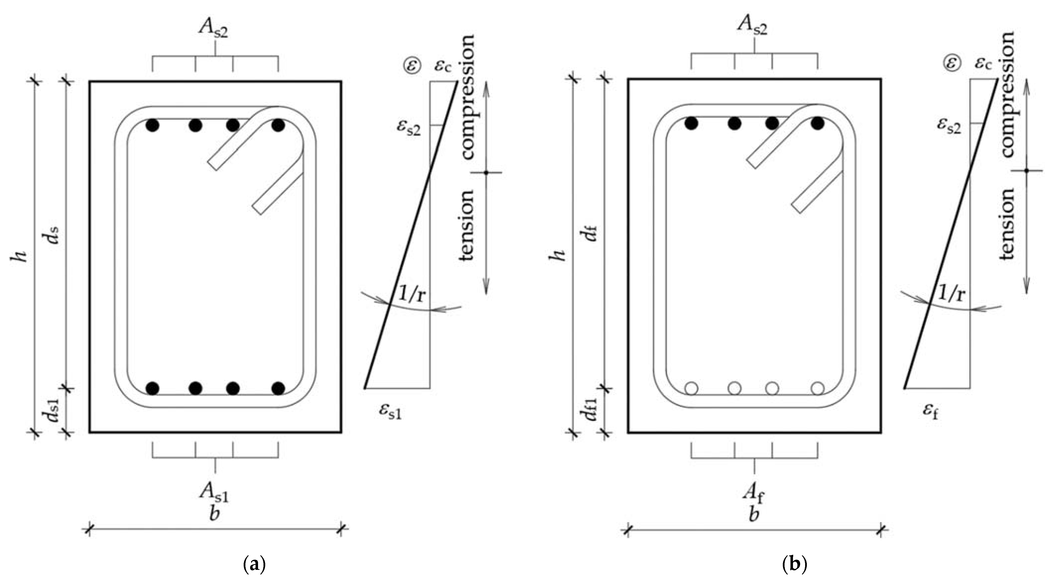
Standard steel reinforced concrete section is shown in Figure 1a with a characteristic strain diagram when subjected to bending moment on the right side of the figure. In Figure 1b the same is shown, only for a section reinforced with FRP rebars on the tensile side. Throughout this paper, steel rebars are hatched with a solid black, while FRP bars have no hatch. Only steel stirrups and steel compressive reinforcement are considered. Similar conclusions could be made if all reinforcement were FRP, but due to more uncertainties about their behavior and modelling, they are not considered in this paper.
In Figure 1, h is height of a section, b is its width, ds is an effective depth of steel reinforced section, ds1 is a distance from the centroid of tensile steel reinforcement to the tensile edge of a section, df is an effective depth of FRP reinforced section, df1 is a distance from the centroid of tensile FRP reinforcement to the tensile edge of a section, As1 is the area of tensile steel reinforcement, As2 is the area of compressive steel reinforcement, Af1 is the area of tensile FRP reinforcement, ε is strain, εc is strain of concrete, εs1 is strain of tensile steel reinforcement, εs2 is strain of compressive steel reinforcement, and εf is strain of FRP reinforcement. A strain profile is drawn in the same plane as a cross section, although it is perpendicular to that plane and is constant along the width of the section. It is usually drawn in the same plane for simplicity, but should be mentioned. The assumption of plane sections remaining plane is visible in strain profiles of Figure 1.
3.1. Modelling of Materials
Concrete is modelled in accordance with a Croatian (and European) design code for concrete structures HRN EN 1992-1-1 [61]. Both confined and unconfined material properties are considered as per EN 12390 [62], depending on the specific detailing of the element. Effectiveness of confinement depends on the amount and distribution of stirrups. Confinement enables concrete to sustain larger stresses and strains by producing a lateral compressive stress. Theoretical explanation of the influence of confinement is given in [63].
Bilinear elastic—ideally a plastic model of steel is used. Strain hardening is not considered in this paper. Strength, modulus of elasticity and ultimate strain are taken from HRN EN 1992-1-1 [61] except when comparing to experimental data where test values are used.
Linear elastic behavior to failure is used to model FRP. When theoretical model results are compared with experimental data, test values of material properties are used, while average values given by rebar manufacturers are used when no experimental data exists.
3.2. Behavior of Concrete Sections Subjected to a Bending Moment
Bending of concrete beams causes their deflection and rotation of cross sections. Curvature of a beam occurs due to a difference in rotation between the sections. Bending moments cause internal forces inside a section. These internal forces, compressive forces in concrete and compressive reinforcement and tensile force in tension reinforcement, need to be in equilibrium. For any given curvature only one bending moment can be found that satisfies equilibrium conditions. In this way, a bending moment–curvature diagram can be formed up to the failure of the section. Depending on the materials and reinforcement detailing, several characteristic points can be determined. The procedure described in the following subsections is based on the procedure explained in [64]. That procedure was then expanded in [65] to consider more complex sections. In this paper, the procedure is expanded to consider the influence of confinement on the behavior of sections.
When cross sections are subjected to axial force in addition to bending moment (e.g., columns), values on the bending moment–curvature change, but it qualitatively stays the same. Procedure does not change, other than the fact that an additional force is added to the equilibrium of forces equation. Axial force is implemented in this model. In this paper, focus will be on reinforced concrete beams which have low or zero axial forces, so it plays little importance and will not be explained further. Detailed background of how axial force should be added to the model is explained in [65]. For columns, confinement of the whole element is usually made, not just the compression area. Ductility of the whole system usually depends more on the behavior of beams, so only beams under bending moment will be discussed in the rest of the paper. Shear forces have little influence on the bending of slender beams so it will have no influence on the proposed model. In addition, it is advisable to avoid shear damage if ductility is to be achieved.
3.2.1. Cracking of Concrete in Tension
The first characteristic point is the cracking of concrete, because behavior changes significantly after concrete cracks in tension. This usually occurs at low curvatures and low bending moments. Theory of elasticity can be used up to this curvature level with sufficient precision. Bending moment corresponding to the cracking of concrete can be determined using the equation:
where fctm is mean tensile strength of concrete. Curvature at cracking can be determined using the equation:
where Ecm is secant modulus of elasticity of concrete and I0 is moment of inertia of uncracked cross section (only concrete). For simplicity, reinforcement can be disregarded when determining the value of second moment of area, as is done in this paper. Cracking is not important when determining the ductility of a section so more complex equations than (3) are not justified in this case.
Mcr = fctm · b · h2/6,
1/rcr = Mcr/(Ecm · I0) = fctm/(0.5 · Ecm · h),
Just after the concrete cracks, the bending moment drops, and curvature remains the same, if displacement control of the element is used in an experiment. If force control is used, then for the same bending moment, curvature rapidly increases. In this paper, displacement control will be considered. The drop of bending moment occurs because after the concrete cracks it is unable to transfer tensile stresses. That means that the whole tensile force is taken by tensile reinforcement. For the same curvature, equilibrium is achieved at a lower level of bending moment.
From a computation point of view, a drop in the bending moment marks a discontinuity and should be addressed. In the procedure used in this paper, integration was stopped when Mcr determined by Equation (2) was reached. The corresponding curvature was determined using Equation (3). This is the point before the drop. The point after the drop was determined by using the same curvature, but instead of using Equation (2) to determine the bending moment, bending moment and force equilibrium of a cracked section were used.
3.2.2. Yielding of a Section with Steel Rebars
When steel reinforcement is used, sections are usually under-reinforced to ensure some level of ductility. Steel as a material yields when steel strain reaches the yield strain of steel εsy. Curvature is varied, keeping the steel strain at the yield value until equilibrium is achieved. Once the equilibrium is achieved, corresponding bending moment My and 1/ry are found.
Iterative numerical analysis was used in this paper to find a force equilibrium. Usually one strain is known; in this case, tensile steel strain. Strain at the compression end is then assumed. For that assumption, the height of compression area x is determined and with it, force in concrete and in compressive reinforcement. If force equilibrium is achieved, then the bending moment and curvature are found. If equilibrium is not achieved, a new value of strain at compressive edge is assumed. Iteration is repeated until equilibrium is found. Strain in concrete cannot be larger than the ultimate compressive strain of unconfined concrete εcu or confined concrete εcu,c. Assumptions of strain at compression edge are made, from zero to the maximum possible value. Once the strain is assumed, compressive area is divided into numerous horizontal strips (e.g., 100). Force in each strip is determined by knowing the strain at that level, determining the stress corresponding to that strain and multiplying it with the area of the strip. Total concrete force is determined by summation of forces in each strip. Mathematically, this can be described by the equation:
where Fc is compressive force in concrete, Fci is compressive force in one strip of compressive area, xi is height of one strip of concrete compressive area and σi is stress in that strip of compressive area. Stress is assumed to be constant in one strip of compressive area and dependent on the stress–strain diagram which is dependent on the achieved level of confinement.
Fc = ∑Fci = ∑b · xi · σi,
The bending moment is determined by multiplying the forces with their distance to an arbitrary point. In this paper, a neutral axis is used. Curvature is simply determined by the equation:
for each of the points of the bending moment–curvature diagram. Equation (5) is also applicable to the cracking point. If it is assumed that half of the section is in tension and concrete strain corresponds to cracking strain, then Equation (5) becomes Equation (3).
1/r = εc/x,
Because the numerical iterative method was used, equilibrium usually cannot be exactly satisfied and some error will always be present. It is assumed in this paper that equilibrium is achieved if the difference between compression and tension forces is less than 1%.
3.2.3. Yielding of a Section with FRP Reinforcement
If FRP reinforcement is used without confining the compression area of concrete, then the section does not yield. If confinement is used, then the section can yield. Since this topic is not adequately researched, “yielding” is an unusual term when talking about FRP reinforced sections. In this paper, this point is named yielding of the section, because at the element level a similar thing happens to steel reinforced elements, and to retain the nomenclature used for steel reinforced elements. As with steel reinforced sections, at this point the behavior of section changes and stiffness starts to reduce due to the damage of an element. Stiffness reduction suggests gradual yielding to the loads, so this name is given to this point even though reinforcement cannot yield.
If compressive area of concrete is confined, then yielding of the section with FRP reinforcement is reached when strain at the compressive edge reaches the value εcu. At that corresponding curvature, crushing of concrete occurs, and it is conservatively assumed in this paper that, at that point, spalling of concrete cover starts. When a small strip at the compressive edge spalls, the section becomes shallower. For an unconfined element this clearly leads to progressive failure since concrete will simply continue to crush uncontrollably. If the compressive area is confined, the bending moment capacity suddenly falls until the whole cover spalls. When spalling reaches the stirrups, they activate and disable the further crushing of concrete inside. Although the section is shallower than before the spalling, the compressive strength of concrete increases due to the confinement and the section can maintain the load bearing capacity. Load bearing capacity could even increase beyond this point because force in FRP continues to increase beyond this point, unlike the force in steel tensile reinforcement which remains the same after yielding. From a computation point of view, a drop in the bending moment is addressed in the same manner as in the case of cracking, i.e., numerical procedure stops just before this discontinuity point and continues just after it.
Existence of this point enables the quantification of curvature ductility capacity of concrete beams reinforced with FRP and confined compressive area.
3.2.4. Section Failure
Failure of standard FRP reinforced beams (with unconfined compressive area) occurs when strain at the compressive edge of the section reaches εcu or when strain at the tensile reinforcement reaches the ultimate rupture strain of FRP εfu. Failure of standard steel reinforced beams (with unconfined compressive area) occurs either when strain at the compressive edge of section reaches εcu or when strain at the tensile rebar reaches the ultimate rupture strain of steel εsu.
For sections with confined compressive area, failure occurs when strain in the stirrups reaches the ultimate rupture strain of steel εsu. This value can be expressed as a function of strain in concrete dependent on the detailing of stirrups. It is also possible that tension failure occurs before rupture of the stirrups if strain at the tensile reinforcement reaches the ultimate rupture strain of steel εsu for steel reinforcement, or when strain at the tensile reinforcement reaches the ultimate rupture strain of FRP εfu.
Other types of failure are also possible such as shear failure, buckling of compressive reinforcement or loss of bond between reinforcement and concrete. All these types of failure provide poor ductility capacity and should be avoided, which is usually accomplished by following the capacity design rules. Corresponding ultimate bending moment Mu and ultimate curvature 1/ru at failure are found using the procedure shown in the previous section.
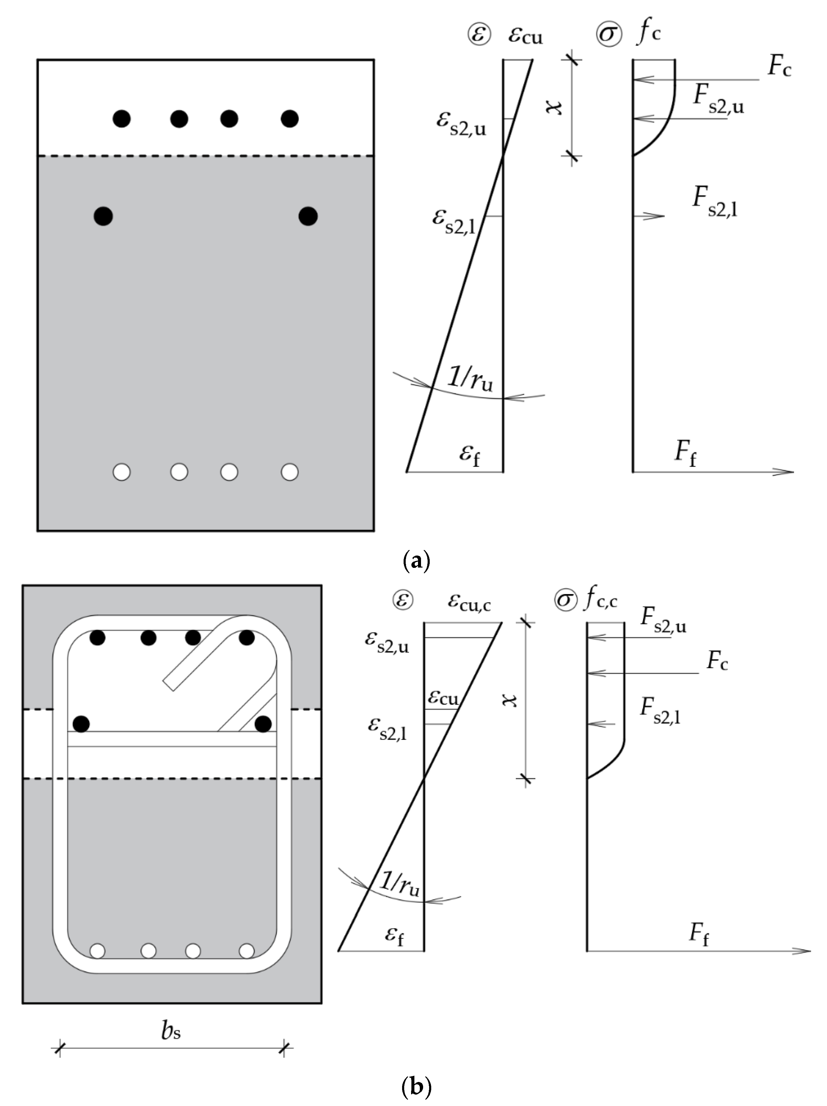
The preferred failure of FRP reinforced beams with a confined compression area is the rupture of confining reinforcement, because this enables higher ductility of an element. Ultimate states of unconfined and confined section are shown in Figure 2.
In Figure 2, εs2,u is the strain of upper compressive reinforcement, εs2,l is the strain of lower compressive reinforcement, εcu,c is the ultimate strain of confined concrete, fc,c is the strength of confined concrete, Fs2,u is the force in upper compressive reinforcement, Fs2,l is the force in lower compressive reinforcement, Fc is the compressive force in concrete and Ff is the force in FRP reinforcement.
Cross section geometries are shown on the left, strain profiles in the middle, and stresses/forces on the far right of the figures. Grey shaded areas are ineffective parts of concrete. Lower parts are cracked due to tension. The shaded area on the upper part of Figure 2b is spalled concrete. It is visible from the stress diagram that concrete above the stirrups is not considered in calculation. Comparing Figure 2a and Figure 2b, it is visible that confined cross sections have higher curvature capacity. Concrete strains of confined cross section are higher than concrete strains of unconfined cross sections at failure.
Figure 2a could also be considered the yielding point of a confined section in Figure 2b because stirrups do not activate until spalling of concrete occurs. After the yielding point, concrete begins to crush, and the grey shaded area becomes larger (for all parts with strain larger than crushing strain). If the strain is smaller than εcu, force in a concrete strip is defined as b · xi · σi, if the strain is between εcu and εcu,c, force in a concrete strip is defined as bs · xi · σi (bs is the width of a stirrup), and if the strain is larger than εcu,c, force in a concrete strip is zero.
3.2.5. Characteristic Bending Moment–Curvature Diagrams
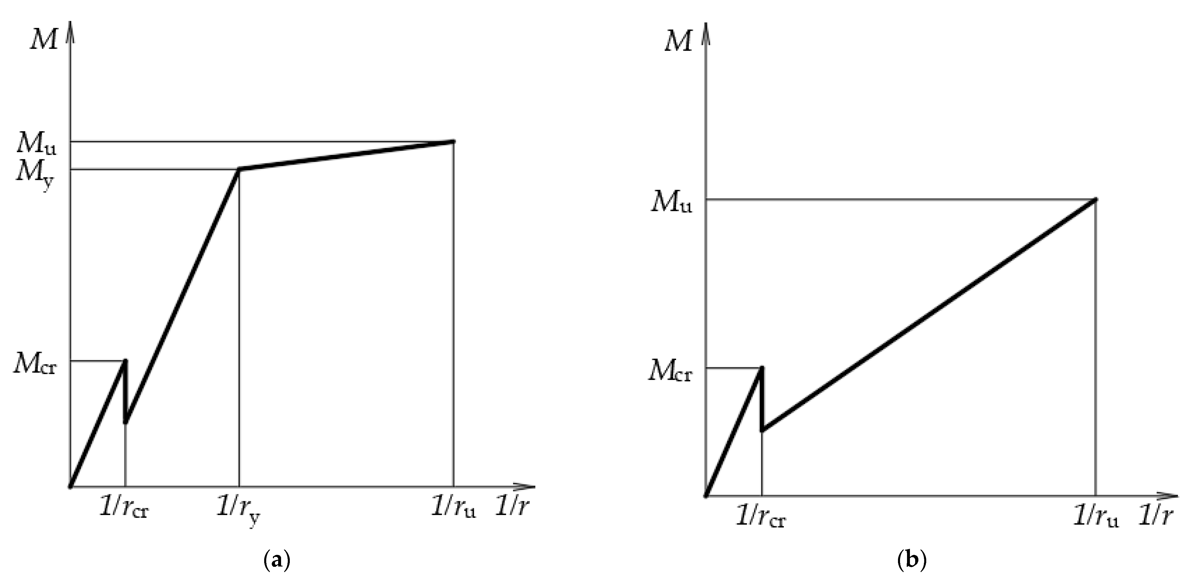
Characteristic bending moment–curvature diagrams for standard steel reinforced section and standard FRP reinforced section are shown in Figure 3a and Figure 3b respectively.
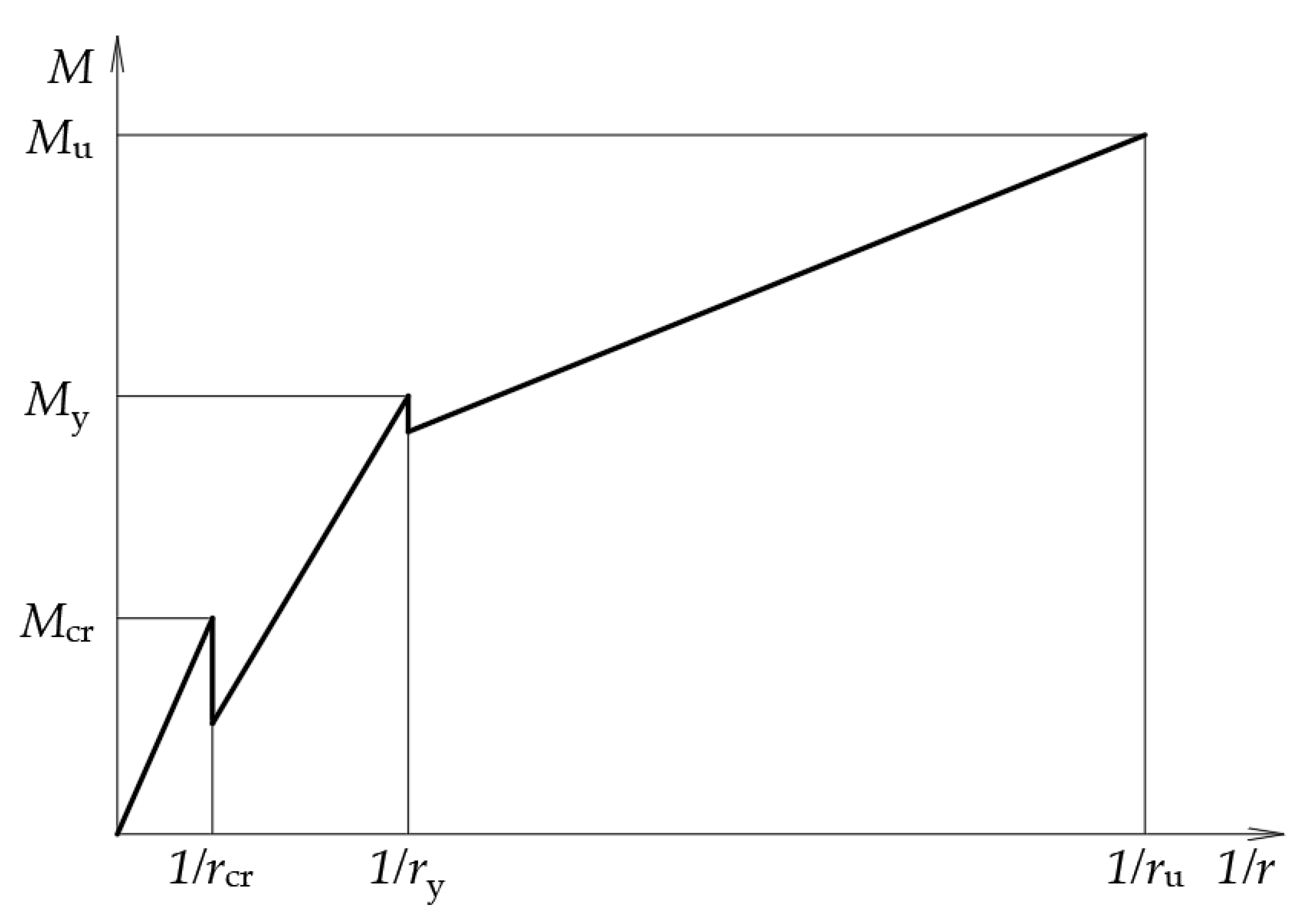
Characteristic bending moment–curvature diagram for FRP reinforced section with confined compression area is shown in Figure 4.
3.3. Behavior of an Element
Once the bending moment–curvature diagram is defined, if loading and support conditions are known, force–deflections diagrams can be determined. In this paper it is assumed that standard relations of curvatures, rotations and deflections are valid.
Beams that are analyzed in this paper are divided into a hundred cross sections along a beam, each subdivided into multiple integration strips. Load is increased from zero to the maximum load in 20 steps. Maximum load is determined as the load that causes the largest bending moment from the bending moment–curvature diagram. If My ≤ Mu, load is increased up to failure.
For any given load level, internal shear forces and bending moments along the element are known. Curvature in each integration point is defined from the bending moment–curvature diagram. This way, the curvature diagram is discretized, and it is considered constant inside one segment (1/100 of a span). Integrating curvatures (multiplying curvature with segment length and adding up all the previous integrations) up to a certain point along the beam produces a rotation at that segment. This way, rotation at the beginning of a beam is zero. This is corrected by considering the end conditions and specific load case. When corrected values of rotation are known at each point along the beam, they are integrated up to a certain point along the beam to determine the deflection at that point. This way, deflection at the end of the beam is maximum, so another correction, now for deflections, needs to be made based on end conditions and loading. When deflection at each point is known, a force–deflection diagram may be constructed. In this paper, total force and displacement at the middle of the span were considered.
It is possible that My > Mu, in which case maximum load corresponds to the bending moment My. Up to that level of load, the procedure is the same as explained in the previous paragraph. After that point, it is not possible to further increase the load since the maximum bending moment is reached. This is explained in [66]. Instead, curvature is increased from 1/ry to 1/ru in 10 additional steps and bending moment is determined from the bending moment–curvature diagram. From that bending moment, a corresponding force is determined. Deflection is determined as before. Different bending moment–curvature diagrams are possible for different parts of the beam if reinforcement is not constant along a beam.
4. Comparison of Theoretical Model with Existing Experimental Data
The proposed model is used to predict the behavior of elements used in existing experimental research. Results from [67] were used to verify that the model can predict the behavior of standard FRP reinforced beams, while results from [26] were used to test the applicability of the model for steel reinforced beams with confined compressive area. The authors were not able to find any research where FRP reinforced concrete beams with confined compressive area were tested. These two studies were selected because material properties, detailing provisions and loading conditions were clearly presented in both, so that all the data required for the model were given. One study should verify the quality of the model for unconfined compressive area and FRP reinforcement while the other should verify it for confined compressive area and steel reinforcement. If the analyses of these two studies show that the model can adequately predict the behavior of the results, it will be assumed that it can also predict the behavior of FRP reinforced concrete beams with a confined compressive area.
In Table 1, experimental results from [67] and results of the theoretical model are shown. Since both mean value and standard deviation of material properties were provided in [67] for concrete, steel and FRP, two values were obtained by modeling. Lower values were obtained by inputting minimal expected values (mean values reduced by two standard deviations). Upper values were obtained by inputting maximal expected values (mean values increased by two standard deviations). Experimental values also had upper and lower values because three beams with the same detailing and materials were tested. Four point bending test on a simply supported beam was used in [67]. Capacity in Table 1 is the total force, i.e., sum of the two loads. Displacement in the middle of the beam is considered. Displacement ductility is defined by the equation:
where uu is deflection at midspan at the point of failure, and uy is deflection at midspan at the point of yielding.
μδ = uu/uy,
When comparing the model with experimental data, it seems that the model overestimates the capacity of GFRP reinforced beams, but this is not necessarily true. It was noted in [67] that the failure occurred by a combination of shear and compressive failure for all GFRP specimens. The proposed model does not consider shear failure explicitly since simple rules on capacity design given in Eurocode (8) apply for beams no matter their material. Calculating shear capacity by Eurocode (2) [61] for tested beams shows that the minimum shear capacity is 81.7 kN. This value is almost the same as the minimum value obtained from results, which could explain the difference in the results. It is known that the variability of the concrete shear strength is high [11] and the code values provide the lowest possible value. Ductility of both the model and experiment are the same. This was expected since the elements are lightly confined and reinforced with FRP.
In Table 2, the experimental results from [26] and results of the theoretical model are shown. Since only mean values of material properties were provided in [26] for concrete and steel, only one value is obtained by modeling. It is visible from the comparison of the values of maximum capacity that the model slightly overestimates the values obtained in the experiment. The overestimation ranges between 1% and 9%. Ductility is sometimes underestimated by the model and sometimes overestimated. The maximum difference is 12%. Both the variation of capacity and ductility are considered acceptable in this paper since concrete behavior is highly variable and some differences of analytical and experimental results are expected. The maximum ductility error of 0.3 (which is 12%) seems reasonably low for any practical analysis.
The proposed model seems to predict the behavior of the analyzed beams with adequate precision and will be accepted in the rest of this paper and used to predict the behavior of beams reinforced with FRP and confined compressive area. Capacity in Table 2 is the total force, i.e., sum of the two loads of the four point bending test.
5. Prediction of Behavior of FRP Reinforced Beams with a Confined Compression Area
As mentioned earlier, there is a lack of experimental data on the behavior of FRP reinforced beams with a confined compression area. An analytical model will be used to predict the behavior of such beams and give guidelines for possible experiments that would confirm the model.
Beams similar to the ones in [67] are used in this analysis to show how the confining of compression can change the behavior of a beam. Three levels of confinement are analysed—low, medium, and high. Since [10] does not give guidance on the design of beams with a confined compression area, a minimum value of confinement for beams is not given. Walls are designed in a way that only the compression ends are confined, so the minimum values for walls are used, in this paper, as a guidance for beams. A low level of confinement is achieved with the value α·ωwd of 0.06, which is smaller than the minimum value for walls of medium ductility, so it corresponds to a low level of ductility DCL. The confinement effectiveness factor, α, depends on the detailing of confinement reinforcement. The mechanical volumetric ratio of confining reinforcement is ωwd. Lateral confinement pressure σ2 of 0.03·fcm is achieved with this confinement, where fcm is mean concrete compression strength. Detailed explanation on determining the confinement pressure is given in [61,63]. Confinement pressure σ2 is defined as 0.5 · α·ωwd·fcm. Medium level of confinement is achieved with the value α·ωwd of 0.10 which is between the minimum value for walls of medium ductility and the minimum value for walls of high ductility, so it corresponds to a medium level of ductility DCM. Lateral confinement pressure σ2 of 0.05·fcm is achieved with this confinement. A high level of confinement is achieved with the value α·ωwd of 0.18, which is higher than the minimum value for walls of high ductility, so it corresponds to a high level of ductility DCH. Lateral confinement pressure σ2 of 0.09·fcm is achieved with this confinement.
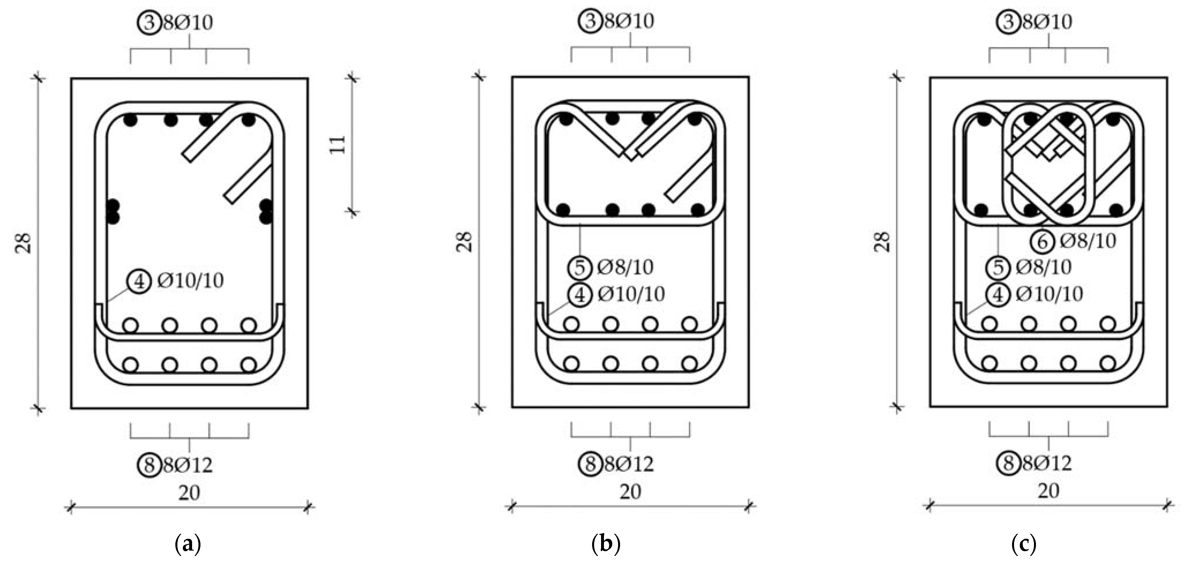
In this theoretical study, some assumptions about material quality and geometry were made. Firstly, concrete class C25/30 was considered and mean value of compressive strength fcm of 33 was used in all of the results. Steel B500B is considered with value of yield strength of 500 N/mm2. Both these assumptions are in accordance with Eurocode 2. The exact amount of confinement steel was determined by considerations shown in the previous paragraph, but also based on practical limitations. To avoid non-ductile shear failure, minimum shear reinforcement was determined, being the minimum confinement that was considered (see Figure 5a). A maximum amount of confinement steel visible in Figure 5c was determined so that it can be constructable. A higher amount of confinement could lead to issues with concrete placement. In short, the lowest considered confinement was defined by shear capacity requirement, and the highest considered confinement was defined by constructability issues. These limits could apply to all elements, regardless of the other parameters of the beam.
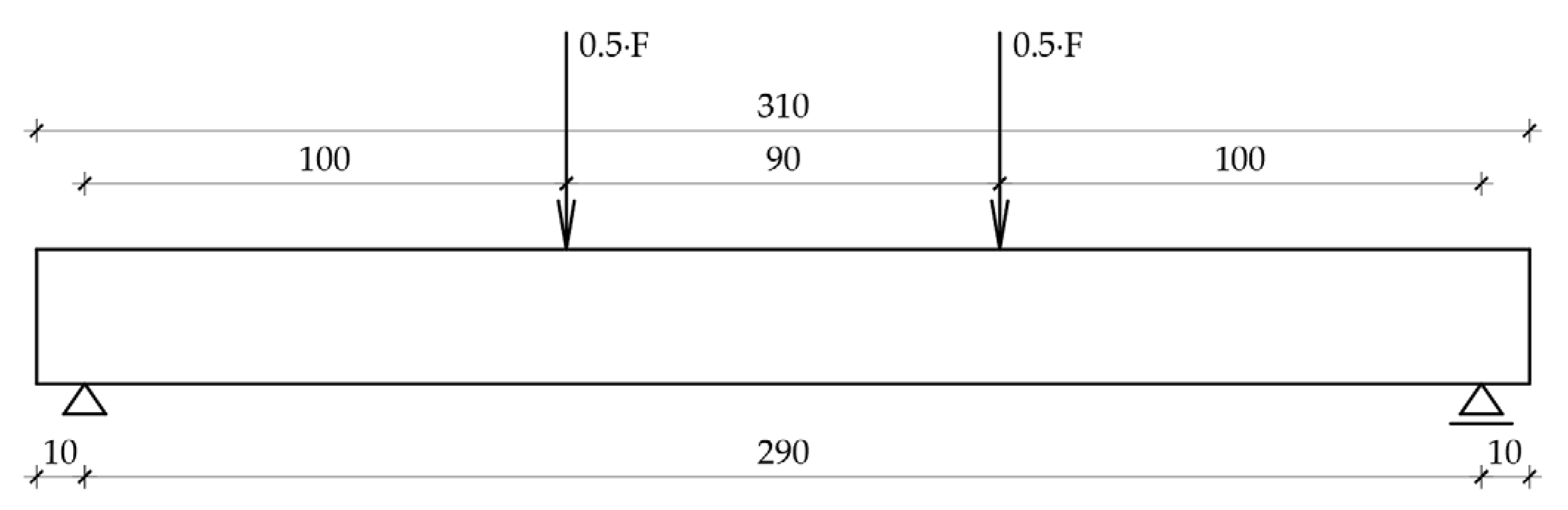
The beam was simply supported with a span of 290 cm loaded with two forces, acting 100 cm from each of the supports. The middle part of the beam, experiencing pure bending, was 90 cm long. The beam was 28 cm high and 20 cm wide. This was the same as the beams in [67]. The difference comes from the internal reinforcement. Internal reinforcement for each of the considered beams is shown in Figure 5.
In Figure 5, ∅ is a diameter sign and / is a spacing sign (perpendicular to the paper plane) in cm. For example, 8∅10 means 8 bars of diameter 10 mm and ∅8/10 means diameter 8 bars on spacing of 10 cm. The beam with dimensions and loads is shown in Figure 6. All values are in centimeters.
Sections shown in Figure 5 differ from one another by the amount of confinement steel. In [67], the section was similar to the one in Figure 5a. The differences were as follows—8 bars were used on the tension side instead of 4, stirrup spacing was smaller, and more compressive reinforcement was used, in this paper. These three changes were made to ensure the intended behavior of beams. Stirrup spacing was reduced in order to ensure that shear failure was completely avoided, something that was not important in [67], but is crucial if ductility is being examined. More compressive reinforcement was used, in this paper, to keep the amount and the centroid of compressive reinforcement the same for all three sections. Since the section in Figure 5c required 8 bars in the compressive area, the same amount was used in all three sections. Compressive steel increases the ductility so if less compressive reinforcement was used in other sections, the influence of confinement could not easily be assessed. Tension bars were GFRP such as in [67], but there were a larger number of them. To achieve high ductility through confinement tension, failure should be avoided, so the amount of tension reinforcement was increased. Tension reinforcement was put in two rows due to congestion issues. When detailing the beam, constructability was considered so that the analyzed beams were not just a theoretical possibility.
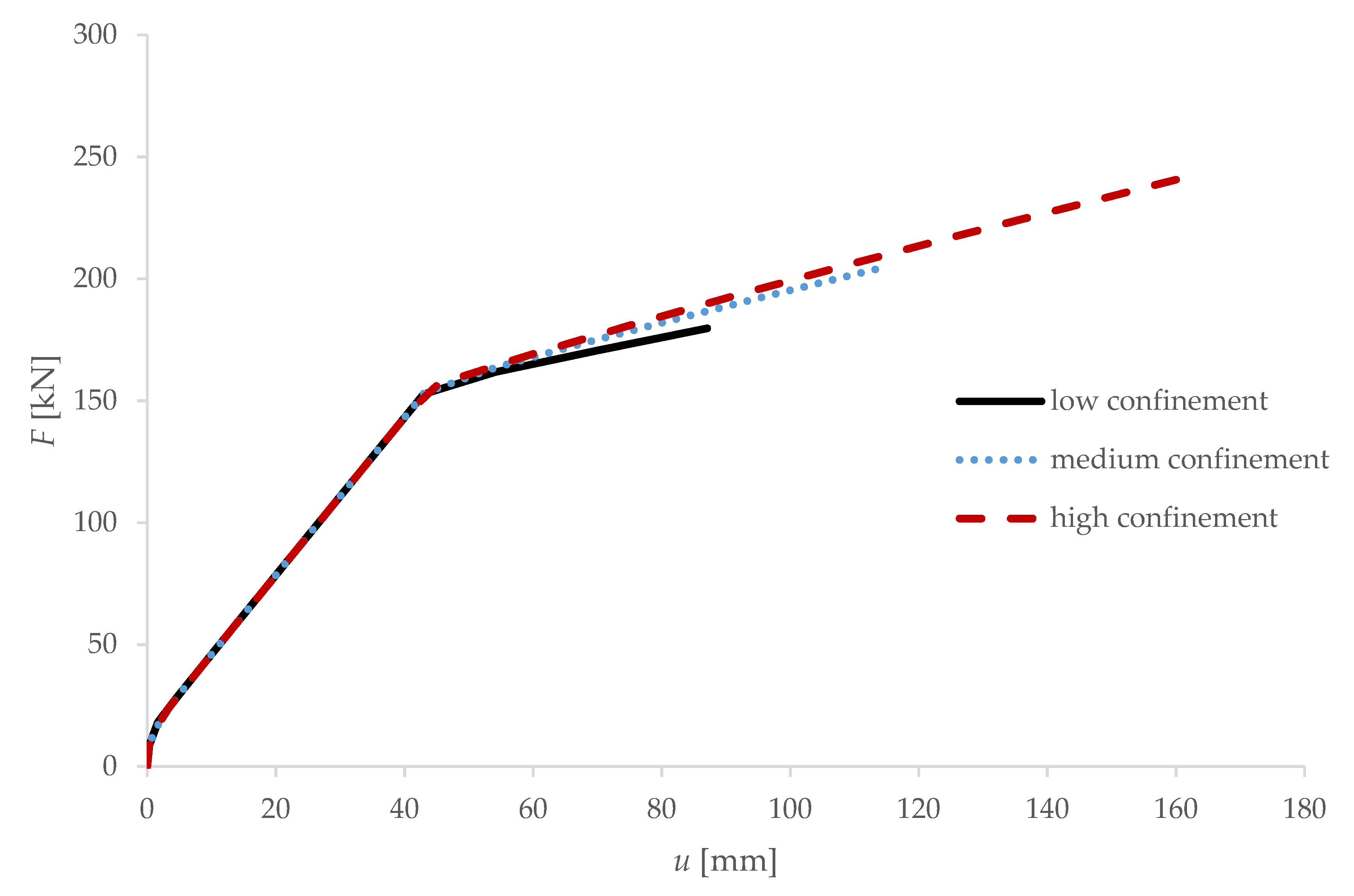
Based on a theoretical analysis using the model proposed in this paper, a force–deflection at midspan diagram is shown in Figure 7, for beams with each of the three proposed levels of confinement. In Figure 7, u is deflection in millimeters, and F (total force, as visible in Figure 7) is force in kilonewtons.
Influence of confinement on the ductility of an element is shown in Figure 8.
6. Discussion
It is visible from Figure 7 that increasing the level of confinement increases both the ductility and capacity of an element. Compared with a beam tested in [67], ductility is significantly higher even for an element with low confinement. This is because ∅10/10 stirrups were used as opposed to ∅8/20 that were used in [67], and the fact that the compressive reinforcement of proposed beams has an approximately six times larger area. This also leads to an increase in capacity because shear failure is avoided and because compressive reinforcement delays the compressive failure. It is visible in Figure 8 that ductility increased by almost two times when comparing high confinement with low confinement. Capacity increased by 20% which is visible in Figure 7. Compared to the results from [67], ductility of highly confined beams increased by four times and capacity by two times, if shear failure was avoided. All beams had the same geometry and were loaded with the same forces, so their comparison seems valid.
In Figure 8, the dotted line is the line of best fit and the equation is related to that line. It is visible that if no confinement exists, ductility is 1.16. This is because a large amount of compressive reinforcement is present. Ratio of mechanical coefficient of tensile and compressive reinforcement is 2.8, which is small compared with 6 that was achieved in [67]. A large amount of compressive reinforcement enabled some ductility even when no confinement was achieved. It seems from this analysis that the relationship between ductility and confining pressure could be reasonably well explained by a linear function.
Since there is a lack of experimental data of beams with FRP reinforcement and confined compressive area it is necessary to confirm results of this analysis by experiments. Beams detailed as shown in Figure 5 could be tested, but other geometries are possible. It should be noted that the mode of failure can significantly influence the ductility so this should be considered in future experimental research. If the results of future experiments show good correlation to the analytical data presented in this paper, then it will be assumed that the proposed model is valid for these types of beams. That would enable parametric analysis to be conducted to research the influence of all the relevant parameters on the ductility and capacity of beams. One of the most important parameters to analyze is the amount and distribution of compressive reinforcement. Another possible step in future research is to consider the same beams, but with all reinforcement being FRP. This should, however, be conducted in steps. It is first necessary to confirm that confining the compressive area increases the ductility. After that, stirrups and compressive reinforcement can be substituted with FRP variants.
Ductility of concrete beams reinforced with longitudinal FRP reinforcement can be increased primarily by confining the compression area of the beam. This can be performed with stirrups. When concrete inside stirrups is compressed, it tends to deform laterally as well as longitudinally. Limiting the lateral deformation by adding stirrups increases the deformation capacity of concrete. In addition to stirrups, ductility can be increased by adding compression reinforcement, but that is less pronounced than for steel reinforced elements. Since failure initially occurs by the crushing of concrete, adding reinforcement in compression can ensure load transfer after crushing starts. In order to avoid buckling of compression bars, stirrups are needed. Other ways of increasing ductility are less effective.
7. Conclusions
Several conclusions can be drawn from the presented paper:
- The analytical model proposed in this paper can adequately predict the behavior of concrete beams reinforced with steel bars and confined compressive area;
- The analytical model proposed in this paper can adequately predict the behavior of concrete beams reinforced with FRP bars and unconfined compressive area;
- Confining the compressive area of concrete beams with FRP reinforcement can significantly increase their ductility and load bearing capacity;
- The failure mechanism can significantly influence the ductility, with bending failure by crushing of confined concrete being the most ductile for confined FRP reinforced beams;
- Ductility is a linear function of lateral confining pressure.
There is a lack of experimental data on the behavior of concrete beams reinforced with FRP and a confined compressive area. Additional experimental research is needed before further analytical research can be made.
Author Contributions
Conceptualization, T.K.; methodology, T.R.; software, T.R. and T.K.; validation, T.K.; formal analysis, T.R.; investigation, T.R.; resources, T.R. and T.K.; data curation, T.K.; writing—original draft preparation, T.R.; writing—review and editing, T.K.; visualization, T.R.; supervision, T.K.; project administration, T.K. All authors have read and agreed to the published version of the manuscript.
Funding
This research received no external funding.
Institutional Review Board Statement
Not applicable.
Informed Consent Statement
Not applicable.
Data Availability Statement
Not applicable.
Conflicts of Interest
The authors declare no conflict of interest.
References
- Clyne, T.W.; Hull, D. An Introduction to Composite Materials, 3rd ed.; Cambridge University Press: Cambridge, UK, 2019; p. 345. [Google Scholar]
- Starkova, O.; Aniskevich, K.; Sevcenko, J. Long-term moisture absorption and durability of FRP pultruded rebars. Mater. Today Proc. 2021, 34, 36–40. [Google Scholar] [CrossRef]
- Benmokrane, B.; Brown, V.L.; Ali, A.H.; Mohamed, K.; Shield, C. Reconsideration of the Environmental Reduction Factor Ce for GFRP Reinforcing Bars in Concrete Structures. J. Compos. Constr. 2020, 24, 06020001. [Google Scholar] [CrossRef]
- Ceroni, F.; Cosenza, E.; Gaetano, M.; Pecce, M. Durability issues of FRP rebars in reinforced concrete members. Cem. Concr. Compos. 2006, 28, 857–868. [Google Scholar] [CrossRef]
- Imjai, T.; Garcia, R.; Guadagnini, M.; Pilakoutas, K. Strength Degradation in Curved Fiber-reinforced Polymer (FRP) Bars Used as Concrete Reinforcement. Polymers 2020, 12, 1653. [Google Scholar] [CrossRef] [PubMed]
- Bai, Y.; Keller, T. Shear Failure of Pultruded Fiber-Reinforced Polymer Composites under Axial Compression. J. Compos. Constr. 2009, 13, 234–242. [Google Scholar] [CrossRef]
- Paulay, T.; Priestley, M.J.N. Seismic Design of Reinforced Concrete and Masonry Buildings; John Wiley & Sons, Inc.: New York, NY, USA, 1992; p. 768. [Google Scholar]
- Priestley, M.J.N.; Calvi, G.M.; Kowalski, M.J. Displacement-Based Seismic Design of Structures, 2nd ed.; IUSS Press: Pavia, Italy, 2017; p. 721. [Google Scholar]
- Pejovic, J.; Stepinac, M.; Serdar, N.; Jevric, M. Improvement of Eurocode 8 Seismic Design Envelope for Bending Moments in RC Walls of High-rise Buildings. J. Earthq. Eng. 2020, 1–25. [Google Scholar] [CrossRef]
- HRN. EN 1998-1:2013, Eurokod 8: Projektiranje Potresne Otpornosti Konstrukcija—1. Dio: Opća Pravila, Potresna Djelovanja i Pravila za Zgrade; HRN: Zagreb, Croatia, 2013. [Google Scholar]
- Park, R.; Paulay, T. Reinforced Concrete Structures; John Wiley & Sons, Inc.: New York, NY, USA, 1975; p. 769. [Google Scholar]
- Kišiček, T.; Stepinac, M.; Renić, T.; Hafner, I.; Lulić, L. Strengthening of masonry walls with FRP or TRM. J. Croat. Assoc. Civ. Eng. 2020, 72, 937–953. [Google Scholar] [CrossRef]
- Bjegović, D.; Štirmer, N. Teorija i Tehnologija Betona; Sveučilište u Zagrebu: Zagreb, Croatia, 2015; p. 1000. [Google Scholar]
- Base, J.B.; Read, G.D. Effectiveness of Helical Binding in the Compression Zone of Concrete Beams. ACI J. Proc. 1965, 62, 763–781. [Google Scholar] [CrossRef]
- Nawy, E.G.; Danesi, R.F.; Grosko, J.J. Rectangular Spiral Binders Effect on Plastic Hinge Rotation Capacity in Reinforced Concrete Beams. ACI J. Proc. 1968, 65, 1001–1010. [Google Scholar] [CrossRef]
- Alasadi, S.; Ibrahim, Z.; Shafigh, P.; Javanmardi, A. An Experimental and Numerical Study on the Flexural Performance of Over-Reinforced Concrete Beam Strengthening with Bolted-Compression Steel Plates: Part II. Appl. Sci. 2020, 10, 94. [Google Scholar] [CrossRef] [Green Version]
- Alasadi, S.; Shafigh, P. Experimental Study on the Flexural Behavior of over Reinforced Concrete Beams Bolted with Compression Steel Plate: Part I. Appl. Sci. 2020, 10, 822. [Google Scholar] [CrossRef] [Green Version]
- Ahmed, M.M.; Farghal, O.A.; Nagah, A.K.; Haridy, A.A. Effect of confining method on the ductility of over-reinforced concrete beams. JES. J. Eng. Sci. 2007, 35, 617–633. [Google Scholar]
- Ali, A.M.; Tarkhan, M.A. Experimental investigation of confining the compression zone in over-reinforced beams. Int. J. Eng. Sci. Res. Technol. 2015, 4, 611–617. [Google Scholar]
- Aylie, H.; Antonius; Okiyarta, A.W. Experimental study of steel-fiber reinforced concrete beams with confinement. Procedia Eng. 2015, 125, 1030–1035. [Google Scholar] [CrossRef] [Green Version]
- Delalibera, R.G.; Giongo, J.S. Theoretical and numerical analysis of reinforced concrete beams with confinement reinforcement. IBRACON Struct. Mater. J. 2008, 1, 17–30. [Google Scholar] [CrossRef] [Green Version]
- Elbasha, N.M. A new reinforced concrete beam. In High Performance Structure and Materials VI, 1st ed.; de Wilde, W.P., Brebbia, C.A., Hernandez, S., Eds.; WIT Press: Suthampton, UK, 2012; pp. 53–62. [Google Scholar] [CrossRef] [Green Version]
- Radnić, J.; Marković, R.; Harapin, A.; Matešan, D. Effect of confined concrete on compressive strength of RC beams. Adv. Concr. Constr. 2013, 1, 215–225. [Google Scholar] [CrossRef]
- Gedara, S.S.S.G.W. Flexural Behaviour of Beams with Confinement. Bachelor’s Thesis, University of Greenwich, London, UK, 2017. [Google Scholar]
- Hadi, M.N.S.; Elbasha, N. Effects of tensile reinforcement ratio and compressive strength on the behaviour of over-reinforced helically confined HSC beams. Constr. Build. Mater. 2007, 21, 269–276. [Google Scholar] [CrossRef]
- Jang, I.-Y.; Park, H.-G.; Kim, Y.-G.; Kim, S.-S.; Kim, J.-H. Flexural Behavior of High-Strength Concrete Beams Confined with Stirrups in Pure Bending Zone. Int. J. Concr. Struct. Mater. 2009, 3, 39–45. [Google Scholar] [CrossRef] [Green Version]
- Mohamed, A.K.; Elamary, A.S.; Ahmed, M.M. Flexural Behaviour of Over Reinforced HSC Beams Confined by Rectangular Ties. J. Eng. Sci. 2008, 36, 1379–1398. [Google Scholar]
- Tee, H.H.; Al-Sanjery, K.; Chiang, J.C.L. Behaviour of Over-reinforced Concrete Beams with Double Helix and Double Square Confinements Related to Ultimate Bending and Shear Strength. J. Phys. Sci. 2018, 29, 77–98. [Google Scholar] [CrossRef] [Green Version]
- Priastiwi, Y.A.; Imran, I. Nuroji The Effect of Different Shapes of Confinement in Compression Zone on Beam’s Ductility Subjected to Monotonic Loading. Procedia Eng. 2015, 125, 918–924. [Google Scholar] [CrossRef] [Green Version]
- Øverli, J.A.; Jensen, T.M. Increasing ductility in heavily reinforced LWAC structures. Eng. Struct. 2014, 62–63, 11–22. [Google Scholar] [CrossRef] [Green Version]
- Wang, H.; Belarbi, A. Ductility characteristics of fiber-reinforced-concrete beams reinforced with FRP rebars. Constr. Build. Mater. 2011, 25, 2391–2401. [Google Scholar] [CrossRef]
- Bartolac, M. Svojstva Predgotovljenih Konstruktivnih Elemenata s Djelomičnom Zamjenom Armature Recikliranim Čeličnim Vlaknima. Ph.D. Thesis, Sveučilište u Zagrebu, Zagreb, Croatia, 2015. [Google Scholar]
- Bouamra, Y.; Aittahar, K. Mechanical performance of a confined reinforced concrete beam. Procedia Struct. Integr. 2017, 5, 155–162. [Google Scholar] [CrossRef]
- Ma, C.-K.; Awang, A.Z.; Garcia, R.; Omar, W.; Pilakoutas, K. Behaviour of over-reinforced high-strength concrete beams confined with post-tensioned steel straps–An experimental investigation. Struct. Concr. 2016, 17, 768–777. [Google Scholar] [CrossRef]
- Barris, C.; Torres, L.; Vilanova, I.; Miàs, C.; Llorens, M. Experimental study on crack width and crack spacing for Glass-FRP reinforced concrete beams. Eng. Struct. 2016, 131, 231–242. [Google Scholar] [CrossRef]
- Sorić, Z.; Kišiček, T.; Galić, J. Deflections of concrete beams reinforced with FRP bars. Mater. Struct. Constr. 2010, 43, 73–90. [Google Scholar] [CrossRef]
- Kišiček, T.; Sorić, Z.; Galić, J. Određivanje progiba betonskih nosača s armaturom od polimera armiranih vlaknima. Građevinar 2008, 60, 499–511. [Google Scholar]
- Barris, C.; Torres, L.; Miàs, C.; Vilanova, I. Design of FRP reinforced concrete beams for serviceability requirements. J. Civ. Eng. Manag. 2012, 18, 843–857. [Google Scholar] [CrossRef]
- FIB. FIB Bulletin 40-FRP Reinforcement in RC Structures; FIB: Lausanne, Switzerland, 2007. [Google Scholar]
- ACI. ACI 440.1R-06: Guide for the Design and Construction of Structural Concrete Reinforced with FRP Bars; ACI: Washington, DC, USA, 2006. [Google Scholar]
- CSA. S806-12: Design and Construction of Building Structures with Fibre-Reinforced Polymers; CSA: Toronto, ON, Canada, 2012. [Google Scholar]
- CNR. CNR-DT 203/2006 Guide for the Design and Construction of Concrete Structures Reinforced with Fiber-Reinforced Polymer Bars; CNR: Rome, Italy, 2007. [Google Scholar]
- JSCE. Recommendation for Design and Construction of Concrete Structures Using Continuous Fiber Reinforcing Materials; JSCE: Tokyo, Japan, 1998. [Google Scholar]
- De Castro, J.; Keller, T. Design of robust and ductile FRP structures incorporating ductile adhesive joints. Compos. Part. B Eng. 2010, 41, 148–156. [Google Scholar] [CrossRef]
- Al-Nimry, H.; Neqresh, M. Confinement effects of unidirectional CFRP sheets on axial and bending capacities of square RC columns. Eng. Struct. 2019, 196, 109323. [Google Scholar] [CrossRef]
- El Maaddawy, T.; El Sayed, M.; Abdel-Magid, B. The effects of cross-sectional shape and loading condition on performance of reinforced concrete members confined with Carbon Fiber-Reinforced Polymers. Mater. Des. 2010, 31, 2330–2341. [Google Scholar] [CrossRef]
- Mostofinejad, D.; Khozaei, K. Effect of GM patterns on ductility and debonding control of FRP sheets in RC strengthened beams. Constr. Build. Mater. 2015, 93, 110–120. [Google Scholar] [CrossRef]
- Kim, H.S.; Shin, Y.S. Flexural behavior of reinforced concrete (RC) beams retrofitted with hybrid fiber reinforced polymers (FRPs) under sustaining loads. Compos. Struct. 2011, 93, 802–811. [Google Scholar] [CrossRef]
- Cai, G.; Tsavdaridis, K.D.; Larbi, A.S.; Purnell, P. A Simplified Design Approach for Predicting the Flexural Behavior of TRM- Strengthened RC Beams under Cyclic Loads. Constr. Build. Mater. 2021, 285, 122799. [Google Scholar] [CrossRef]
- Bazan, J.L.; Fernandez-Davila, V.I. Evaluation of the experimental curvature ductility of RC beams externally strengthened with CFRP bands. Structures 2020, 26, 1010–1020. [Google Scholar] [CrossRef]
- Mostofinejad, D.; Anaei, M.M. Effect of confining of boundary elements of slender RC shear wall by FRP composites and stirrups. Eng. Struct. 2012, 41, 1–13. [Google Scholar] [CrossRef]
- Gibhardt, D.; Doblies, A.; Meyer, L.; Fiedler, B. Fatigue and Mechanical Properties of Glass Fibre Reinforced Epoxy. Materials 2019, 7, 55. [Google Scholar] [CrossRef] [Green Version]
- Belzer, B.E.; Robinson, M.J.; Fick, D.R. Composite Action of Concrete-Filled Rectangular GFRP Tubes. J. Compos. Constr. 2013, 17, 722–731. [Google Scholar] [CrossRef]
- Huang, L.; Zhang, C.; Yan, L.; Kasal, B. Flexural Behavior of U-shape FRP Profile-RC Composite Beams with Inner GFRP Tube Confinement at Concrete Compression Zone. Compos. Struct. 2018, 184, 674–687. [Google Scholar] [CrossRef]
- Lam, L.; Teng, J.G. Design-oriented stress–strain model for FRP-confined concrete. Constr. Build. Mater. 2003, 17, 471–489. [Google Scholar] [CrossRef]
- Rousakis, T.C.; Rakitzis, T.D.; Karabinis, A.I. Design-Oriented Strength Model for FRP-Confined Concrete Members. J. Compos. Constr. 2012, 16, 615–625. [Google Scholar] [CrossRef]
- Yuan, F.; Chen, M.; Pan, J. Experimental study on seismic behaviours of hybrid FRP–steel-reinforced ECC–concrete composite columns. Compos. Part. B Eng. 2019, 176, 1–10. [Google Scholar] [CrossRef]
- Renić, T.; Hafner, I.; Kišiček, T. Ductility of hybrid FRP-steel reinforced concrete sections. In Proceedings of the 2nd International Conference CoMS 2020/21, Ljubljana, Slovenia, 20–21 April 2021; Šajna, A., Legat, A., Jordan, S., Horvat, P., Kemperle, E., Dolenc, S., Ljubešek, M., Michelizza, M., Eds.; Slovenian National Building and Civil Engineering Institute: Ljubljana, Slovenia. [Google Scholar]
- Harris, H.G.; Somboonsong, W.; Ko, F.K. New Ductile Hybrid FRP Reinforcing Bar for Concrete Structures. J. Compos. Constr. 1998, 2, 28–37. [Google Scholar] [CrossRef]
- Abeer, S.Z.; Dawood, M.B.; Ghalib, M.H. Using 2D digital image correlation to investigate the flexural behavior of continuous composite beams. Mater. Sci. Eng. 2020, 888, 1–11. [Google Scholar] [CrossRef]
- HRN. EN 1992-1-1:2013, Eurokod 2: Projektiranje Betonskih Konstrukcija-Dio 1-1: Opća Pravila i Pravila za Zgrade; HRN: Zagreb, Croatia, 2011. [Google Scholar]
- HRN. EN 12390-3:2012, Ispitivanje Očvrslog Beotna-Dio 3: Tlačna Čvrstoća Uzoraka; HRN: Zagreb, Croatia, 2012. [Google Scholar]
- Mander, J.B.; Priestley, M.J.N.; Park, R. Theoretical Stress-Strain Model for Confined Concrete. J. Struct. Eng. 1988, 114, 1804–1826. [Google Scholar] [CrossRef] [Green Version]
- Kišiček, T.; Sorić, Z. Dijagram moment savijanja–zakrivljenost za armiranobetonske gredne elemente. Građevinar 2003, 55, 207–215. [Google Scholar]
- Kišiček, T.; Renić, T.; Lazarević, D.; Hafner, I. Compressive Shear Strength of Reinforced Concrete Walls at High Ductility Levels. Sustainability 2020, 12, 4434. [Google Scholar] [CrossRef]
- Kišiček, T.; Carić, M.; Frančić Smrkić, M.; Renić, T.; Damjanović, D. Flexural behaviour of hybrid steel fibre reinforced concrete (HSFRC). In Proceedings of the International Conference on Sustainable Materials, Systems and Structures, Rovinj, Croatia, 20–22 March 2019. [Google Scholar]
- Kišiček, T. Progibi Betonskih Greda s FRP Armaturom. Ph.D. Thesis, Sveučilište u Zagrebu, Zagreb, Croatia, 2006. [Google Scholar]
Figure 1.
Concrete cross sections with strain diagram: (a) Steel reinforced section; (b) FRP reinforced section.
Figure 1.
Concrete cross sections with strain diagram: (a) Steel reinforced section; (b) FRP reinforced section.

Figure 2.
Ultimate state of FRP reinforced beams: (a) Unconfined section; (b) Confined section.

Figure 3.
Bending moment–curvature diagrams: (a) Unconfined steel reinforced section; (b) Unconfined FRP reinforced section.
Figure 3.
Bending moment–curvature diagrams: (a) Unconfined steel reinforced section; (b) Unconfined FRP reinforced section.

Figure 4.
Bending moment–curvature diagram for FRP reinforced section with a confined compression area.
Figure 4.
Bending moment–curvature diagram for FRP reinforced section with a confined compression area.

Figure 5.
Beam sections: (a) Low confinement; (b) Medium confinement; (c) High confinement.

Figure 6.
Geometry and loading conditions of the beam.

Figure 7.
Force–deflection diagram for three different levels of confinement.

Figure 8.
Influence of confinement on displacement ductility.


Table 1.
Comparison of results from [67] with theoretical model results.
Table 1.
Comparison of results from [67] with theoretical model results.
| Sample | Capacity (kN) | Displacement Ductility μδ (-) |
|---|---|---|
| experiment GFRP | 81.8–113.3 | 1.0 |
| model GFRP | 110.7–130.8 | 1.0 |
| experiment CFRP | 216.2–222.4 | 1.0 |
| model CFRP | 175.2–231.5 | 1.0 |
Table 2.
Comparison of results from [26] with theoretical model results.
Table 2.
Comparison of results from [26] with theoretical model results.
| Sample | Capacity (kN) | Displacement Ductility (-) |
|---|---|---|
| 4B4-0.5 (0) experiment | 120.6 | 3.6 |
| 4B4-0.5 (0) model | 130.9 | 3.7 |
| 4B4-0.5 (10) experiment | 115.3 | 3.8 |
| 4B4-0.5 (10) model | 120.0 | 3.8 |
| 4B4-0.7 (5) experiment | 148.6 | 3.1 |
| 4B4-0.7 (5) model | 155.4 | 3.0 |
| 4B4-0.7 (10) experiment | 149.6 | 2.5 |
| 4B4-0.7 (10) model | 158.7 | 2.2 |
| 4B4-1.0 (10) experiment | 184.6 | 2.1 |
| 4B4-1.0 (10) model | 198.7 | 2.1 |
| 4B4-1.0 (5) experiment | 181.8 | 2.6 |
| 4B4-1.0 (5) model | 197.0 | 2.9 |
| 7B4-0.5 (0) experiment | 165.0 | 2.4 |
| 7B4-0.5 (0) model | 180.4 | 2.2 |
| 7B4-0.5 (10) experiment | 163.6 | 3.4 |
| 7B4-0.5 (10) model | 178.5 | 3.4 |
| 7B4-0.7 (5) experiment | 212.4 | 2.0 |
| 7B4-0.7 (5) model | 214.9 | 2.0 |
| 7B4-0.7 (10) experiment | 200.7 | 1.9 |
| 7B4-0.7 (10) model | 217.6 | 2.1 |
Publisher’s Note: MDPI stays neutral with regard to jurisdictional claims in published maps and institutional affiliations. |
© 2021 by the authors. Licensee MDPI, Basel, Switzerland. This article is an open access article distributed under the terms and conditions of the Creative Commons Attribution (CC BY) license (https://creativecommons.org/licenses/by/4.0/).
Share and Cite
MDPI and ACS Style
Renić, T.; Kišiček, T. Ductility of Concrete Beams Reinforced with FRP Rebars. Buildings 2021, 11, 424. https://doi.org/10.3390/buildings11090424
AMA Style
Renić T, Kišiček T. Ductility of Concrete Beams Reinforced with FRP Rebars. Buildings. 2021; 11(9):424. https://doi.org/10.3390/buildings11090424
Chicago/Turabian StyleRenić, Tvrtko, and Tomislav Kišiček. 2021. "Ductility of Concrete Beams Reinforced with FRP Rebars" Buildings 11, no. 9: 424. https://doi.org/10.3390/buildings11090424
Note that from the first issue of 2016, this journal uses article numbers instead of page numbers. See further details here.