
Damage Assessment of Reinforced Concrete Elements Due to Corrosion Effect Using Dynamic Parameters: A Review


Abstract
:1. Introduction
2. Damage Detection Methods Using Change of Dynamic Parameters
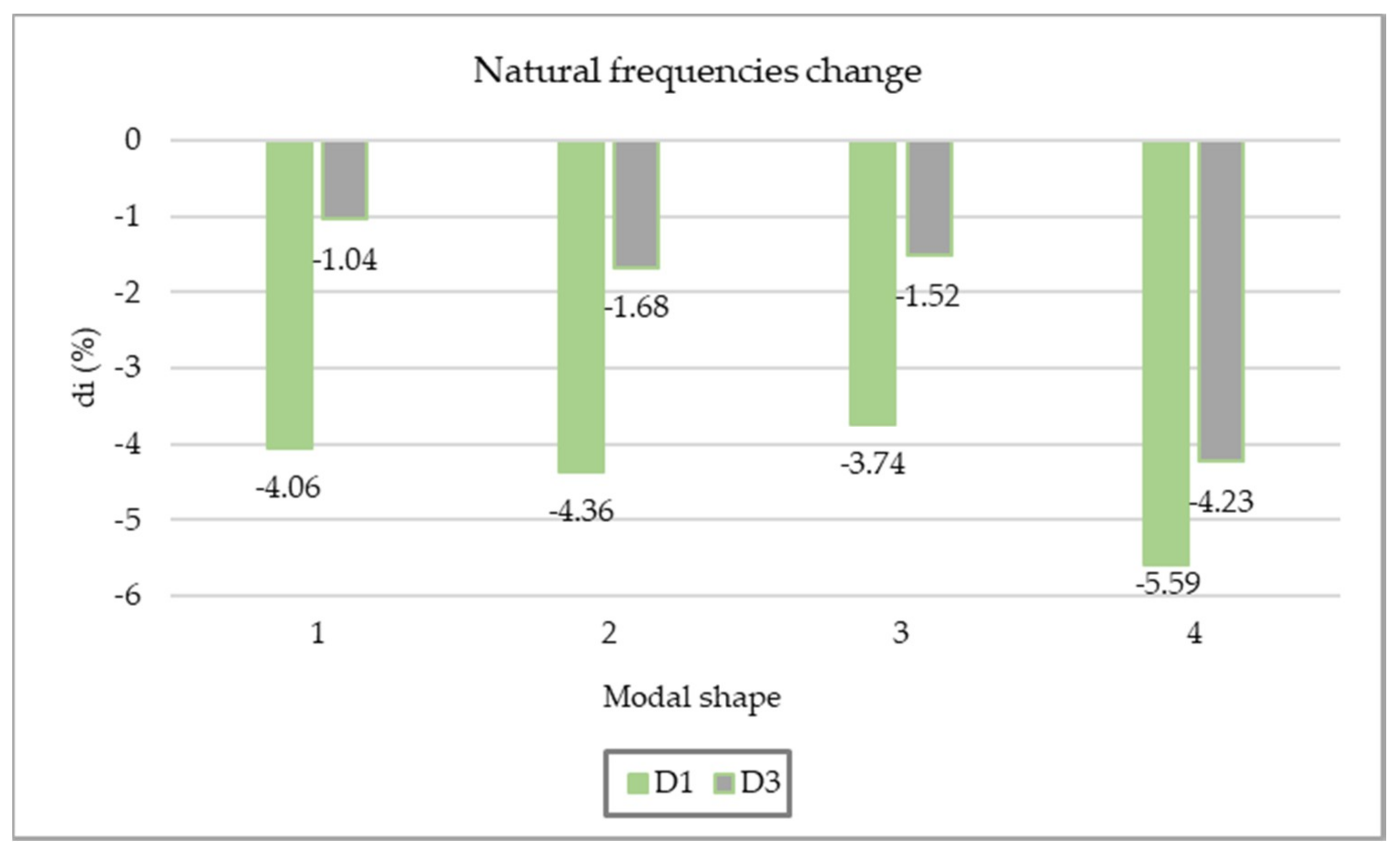
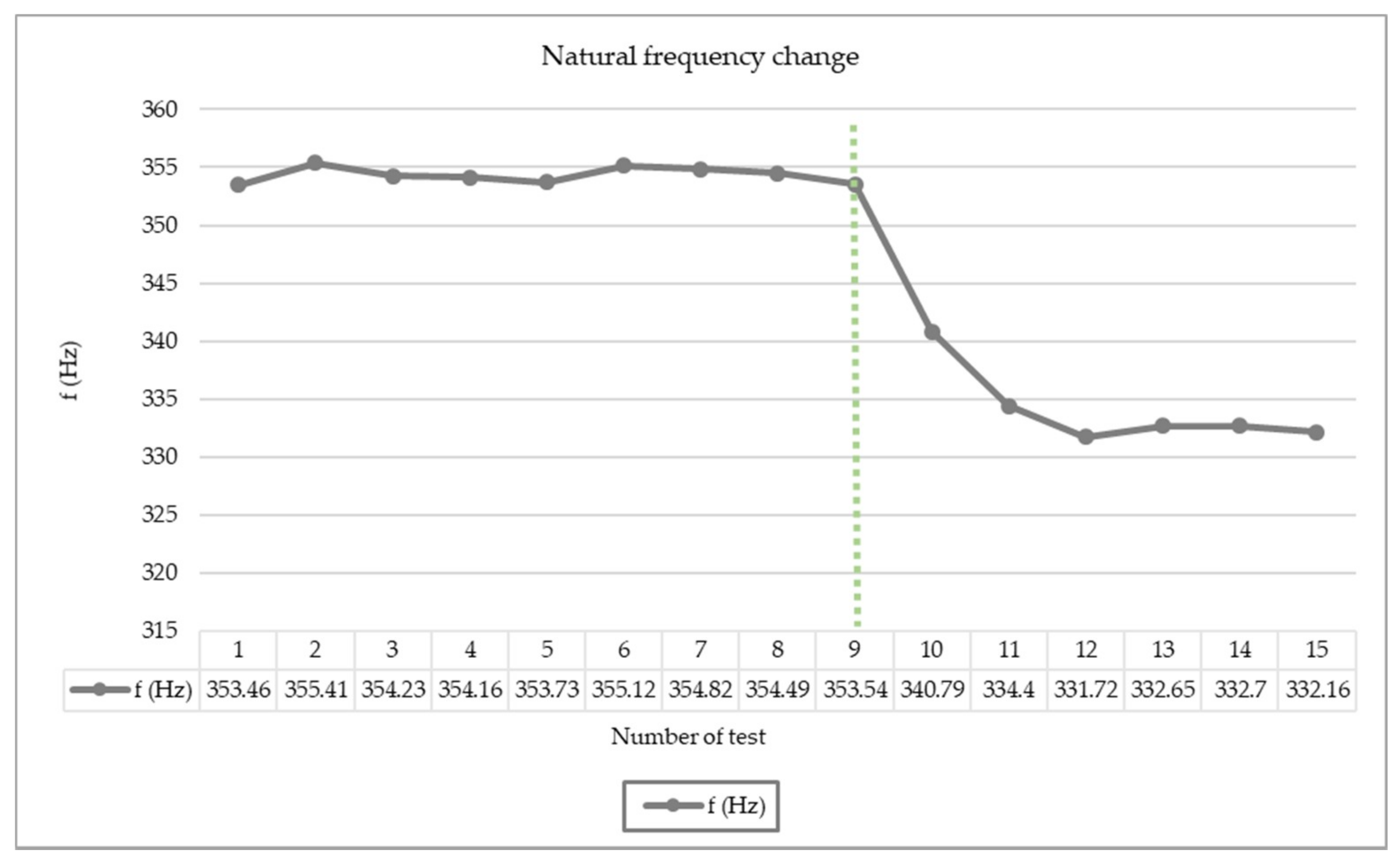
2.1. Changing of Natural Frequencies
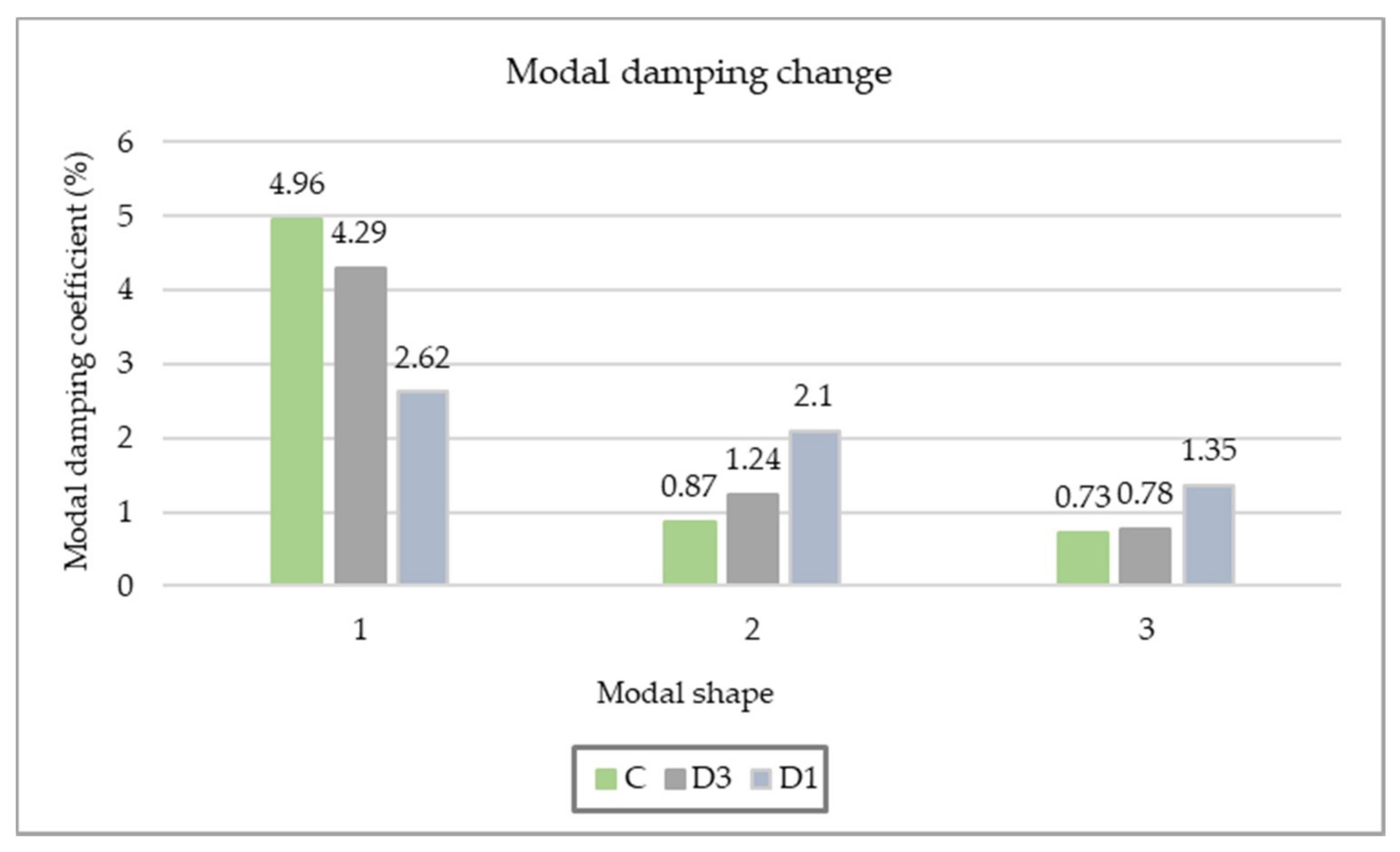
2.2. Modal Damping Change
2.3. Change of Mode Shapes—MAC, COMAC
2.4. Mode Shape Curvature Method
2.5. Changing the Modal Flexibility
2.6. Discussion
3. Determination of Corrosion on Reinforced Concrete Elements Using Vibration-Based Methods—A Review
3.1. Research Review and Result Analysis
3.2. Synthesis of Results
4. Conclusions
Author Contributions
Funding
Institutional Review Board Statement
Informed Consent Statement
Data Availability Statement
Conflicts of Interest
References
- Morgese, M.; Ansari, F.; Domaneschi, M.; Cimellaro, G.P. Post collapse analysis of Morandi’s Polcevera vidauct in Genoa Italy. J. Civ. Struct. Health Monit. 2020, 10, 69–85. [Google Scholar] [CrossRef]
- Deng, L.; Wang, W.; Yu, Y. State-of-the-art review on the causes and mechanisms of bridge collapse. J. Perform. Constr. Facil. 2016, 30, 04015005. [Google Scholar] [CrossRef]
- Choudhury, J.R.; Hasnat, A. Bridge collapses around the world: Causes and mechanisms. In Proceedings of the IABSE-JSCE Joint Conference on Advances in Bridge Engineering, Dhaka, Bangladesh, 21–25 August 2015; p. 34. [Google Scholar]
- Woodward, R. Bridge Managament in Europe (BRIME)—Final Report; Transport Research Laboratory: Crowthorne, UK, 2001. [Google Scholar]
- Calvi, G.M.; Moratti, M.; O´Reilly, G.J.; Scattarreggia, N.; Monteiro, R.; Malomo, D.; Calvi, P.M.; Pinho, R. Once upon a time in Italy: The tale of the Morandi Bridge. Struct. Eng. Int. 2019, 29, 198–217. [Google Scholar] [CrossRef]
- Clemente, M. Monitoring and evaluation of bridges: Lessons from the Polcevera Viaduct collapse in Italy. J. Civ. Struct. Health Monit. 2020, 10, 177–182. [Google Scholar] [CrossRef]
- Rodriguez, J.; Ortega, L.M.; Casal, J. Load carrying capacity of concrete structures with corroded reinforcement. Constr. Build. Mater. 1997, 11, 239–248. [Google Scholar] [CrossRef]
- Castel, A.; François, R.; Arliguie, G. Mechanical behaviour of corroded reinforced concrete beams—Part 2: Bond and notch effects. Mater. Struct. 2000, 33, 545–551. [Google Scholar] [CrossRef]
- Fernandez, I.; Bairán, J.M.; Marí, A.R. Corrosion effects on the mechanical properties of reinforcing steel bars. Fatigue and σ–ε behavior. Constr. Build. Mater. 2015, 101, 772–783. [Google Scholar] [CrossRef]
- Wu, J.; Wu, S.X. Location of damage due to corrosion in reinforced concrete structures. In Proceedings of the 28th Conference on Our World in Concrete & Structures, Singapore, 28–29 August 2003; pp. 595–601. [Google Scholar]
- Wang, L.; Li, T.; Dai, L.; Chen, W.; Huang, K. Corrosion morphology and mechanical behavior of corroded prestressing strands. J. Adv. Concr. Technol. 2020, 18, 545–557. [Google Scholar] [CrossRef]
- Ma, Y.; Peng, A.; Su, X.; Wang, L.; Zhang, J. Modeling constitutive relationship of steel bar removed from corroded PC beams after fatigue considering spatial location effect. J. Mater. Civ. Eng. 2021, 33, 04021019. [Google Scholar] [CrossRef]
- Cornwell, P.; Farrar, C.R.; Doebling, S.W.; Sohn, H. Environmental variability of modal properties. Exp. Tech. 1999, 23, 45–48. [Google Scholar] [CrossRef]
- Duvnjak, I. Damage Assessment on Plate Structures Using Dynamic Parameters. Ph.D. Thesis, Faculty of Civil Engineering, University of Zagreb, Zagreb, Croatia, 2015. [Google Scholar]
- Raupach, M.; Reichling, K.; Broomfield, J.; Gulikers, J.; Schneck, U.; Serdar, M.; Pepenar, I. Inspection strategies for reinforcement corrosion surveys. Mater. Corros. 2012, 64, 111–115. [Google Scholar] [CrossRef]
- Wang, L.; Chan, T.H. Review of vibration-based damage detection and condition assessment of bridge structures using structural health monitoring. In Proceedings of the Second Infrastructure Theme Postgraduate Conference: Rethinking Sustainable Development: Planning, Engineering, Design and Managing Urban Infrastructure, Brisbane, QLD, Australia, 26 March 2009; pp. 1–15. [Google Scholar]
- Doebling, S.W.; Farrar, C.R.; Prime, M.B. A summary review of vibration—Based damage identification methods. Shock. Vib. Dig. 1998, 30, 91–105. [Google Scholar] [CrossRef] [Green Version]
- Fayyadh, M.M.; Razak, H.A. Damage identification and assessment in RC structures using vibration data: A review. J. Civ. Eng. Manag. 2013, 19, 375–386. [Google Scholar] [CrossRef] [Green Version]
- Kong, X.; Cai, C.S.; Hu, J. The state-of-the-art on framework of vibration-based structural damage identification for decision making. Appl. Sci. 2017, 7, 497. [Google Scholar] [CrossRef] [Green Version]
- Rytter, A. Vibrational Based Inspection of Civil Engineering Structures. Ph.D. Thesis, Department of Building Technology and Structural Engineering, Aalborg University, Aalborg, Denmark, 1993. [Google Scholar]
- Moughty, J.J.; Casas, J.R. A state of the art review of modal-based damage detection in bridges: Development, challenges, and solution. Appl. Sci. 2017, 7, 510. [Google Scholar] [CrossRef] [Green Version]
- Salawu, O.S. Detection of structural damage through changes in frequency: A review. Eng. Struct. 1997, 19, 718–723. [Google Scholar] [CrossRef]
- Salehi, M.; Ziaeirad, S.; Ghayour, M.; Vazirizanjani, M.A. A structural damage detection technique based on measured frequency response function. Contemp. Eng. Sci. 2010, 3, 215–226. [Google Scholar]
- Adams, R.D.; Cawley, P.; Pye, C.J.; Stone, B.J. A vibration technique for non-destructively assessing the integrity of structures. J. Mech. Eng. Sci. 1978, 20, 93–100. [Google Scholar] [CrossRef]
- Messina, A.; Williams, E.; Contursi, T. Structural damage detection by a sensitivity and statistical-based method. J. Sound Vib. 1998, 216, 791–808. [Google Scholar] [CrossRef]
- Shih, H.W.; Thambiratnam, D.P.; Chan, T.H. Vibration based structural damage detection in flexural members using multi criteria approach. J. Sound Vib. 2009, 323, 645–661. [Google Scholar] [CrossRef]
- Baktiari-Nejad, F.; Esfandiari, A.; Rahai, A. Structural damage detection and assessment using measured natural frequencies. In Proceedings of the 23rd International Modal Analysis Conference, Orlando, FL, USA, 31 January–3 February 2005. [Google Scholar]
- Jeary, A.P.; Ellis, B.R. Non-destructive in-situ testing using dynamic techniques. In Proceedings of the 3rd International Conference on Tall Buildings, Hong Kong, China, 10–15 December 1984; pp. 76–81. [Google Scholar]
- Sohn, H.; Farrar, C.R.; Hemez, F.M.; Shunk, D.D.; Stinemates, D.W.; Nadler, B.R.; Czarnecki, J.J. A Review of Structural Health Monitoring Literature: 1996–2001; Los Alamos National Laboratories: Los Alamos, NM, USA, 2004; p. 311. [Google Scholar]
- Hearn, G.; Testa, R.B. Modal analysis for damage detection in structures. J. Struct. Eng. 1991, 117, 3042–3063. [Google Scholar] [CrossRef]
- Gade, S.; Møller, N.B.; Herlufsen, H.; Konstantin-Hansen, H.; Anderson, P. Frequency domain techniques for operational modal analysis. In Proceedings of the 1st IOMAC Conference, Copenhagen, Denmark, 26–27 April 2005; pp. 261–271. [Google Scholar]
- Wang, L. Innovative Damage Assessment of Steel Truss Bridges Using Modal Strain Energy Correlation. Ph.D. Thesis, Queensland University of Technology, Brisbane, QLD, Australia, 2012. [Google Scholar]
- Eyre, R.; Tily, G.P. Damping measurements on steel and composite bridges. In Proceedings of the Symposium on Dynamic Behaviour of Bridges at the Transport and Road Research Laboratory, Crowthorne, UK, 19 May 1977; pp. 22–39. [Google Scholar]
- Whalen, T.M. The behavior of higher order mode shape derivatives in damaged, beam-like structures. J. Sound Vib. 2008, 309, 426–464. [Google Scholar] [CrossRef]
- Fayyadh, M.M.; Razak, H.A. Detection of damage location using mode shape deviation: Numerical study. Int. J. Phys. Sci. 2011, 6, 5688–5698. [Google Scholar] [CrossRef]
- Farrar, C.R.; James, G.H. System identification from ambient vibration measurements on a bridge. J. Sound Vib. 1997, 205, 1–18. [Google Scholar] [CrossRef]
- Allemang, R.J.; Brown, D.L. A correlation coefficient for modal vector analysis. In Proceedings of the 1st International Modal Analysis Conference, Orlando, FL, USA, 8–10 November 1982; pp. 110–116. [Google Scholar]
- West, M. Illustration of the use of modal assurance criterion to detect structural changes in an orbiter test specimen. In Proceedings of the Air Conference on Aircraft Structural Integrity, Palm Springs, CA, USA, 1984; pp. 1–6. [Google Scholar]
- Kim, J.H.; Jeon, H.S.; Lee, C.W. Application of the modal assurance criteria for detecting and locating structural faults. In Proceedings of the 10th International Modal Analysis Conference, San Diego, CA, USA, 3–7 February 1992; pp. 536–540. [Google Scholar]
- Dutta, A.; Talukdar, S. Damage detection in bridges using accurate modal parameters. Finite Elem. Anal. Des. 2004, 40, 287–304. [Google Scholar] [CrossRef]
- Pandey, A.K.; Biswas, M.; Samman, M.M. Damage detection from changes in curvature mode shapes. J. Sound Vib. 1991, 145, 321–332. [Google Scholar] [CrossRef]
- Maeck, J.; De Roeck, G. Damage detection on a prestressed concrete bridge and RC beams using dynamic system identification. Key Eng. Mater. 1999, 167–168, 320–327. [Google Scholar] [CrossRef]
- Wahab, M.A.; De Roeck, G. Damage detection in bridges using modal curvatures: Application to a real damage scenario. J. Sound Vib. 1999, 226, 217–235. [Google Scholar] [CrossRef]
- Ho, Y.K.; Ewins, D.J. On structural damage identification with mode shapes. In Proceedings of the European COST F3 Conference on System Identification & Structural Health Monitoring, Madrid, Spain, 6–9 June 2000; pp. 677–684. [Google Scholar]
- Farrar, C.R.; Worden, K. Structural Health Monitoring—A Machine Learning Perspective, 1st ed.; John Wiley & Sons: Hoboken, NJ, USA, 2013. [Google Scholar]
- Pandey, A.K.; Biswas, M. Damage detection in structures using changes in flexibility. J. Sound Vib. 1994, 169, 3–17. [Google Scholar] [CrossRef]
- Toksoy, T.; Aktan, A. Bridge condition assessment by modal flexibility. Exp. Mech. 1994, 34, 271–278. [Google Scholar] [CrossRef]
- Zhang, Z.; Aktan, A.E. The damage indices for constructed facilities. In Proceedings of the 13th International Modal Analysis Conference, Nashville, TN, USA, 13–16 February 1995; pp. 1520–1529. [Google Scholar]
- Patjawit, A.; Kanok-Nukulchai, W. Health monitoring of highway bridges based on a Global Flexibility Indeks. Eng. Struct. 2005, 27, 1385–1391. [Google Scholar] [CrossRef]
- Capozucca, R. Damage assessment in PRC and RC beams by dynamic tests. J. Phys. Conf. Ser. 2011, 305, 12098–12107. [Google Scholar] [CrossRef]
- Shahzad, S.; Yamaguchi, H.; Takanami, R.; Asamoto, S. Detection of corrosion-induced damage in reinforced concrete beams based on structural damping identification. In Proceedings of the Thirteenth East Asia-Pacific Conference on Structural Engineering and Construction (EASEC-13), Sapporo, Japan, 11–13 September 2013; pp. G-2-4–G-2-11. [Google Scholar]
- Zuccarino, L.; De Leonardis, A.; Di Evangelista, A.; Valente, C. Sensitivity of modal parameters for damage detection in corroded beam elements of the Pescara benchmark. J. Phys. Conf. Ser. 2011, 305, 12082–12091. [Google Scholar] [CrossRef]
- Razak, H.A.; Choi, F.C. The effect of corrosion on the natural frequency and modal damping of reinforced concrete beams. Eng. Struct. 2001, 23, 1126–1133. [Google Scholar] [CrossRef]
- Ortega, N.F.; Robles, S.I. Assessment of Residual Life of concrete structures affected by reinforcement corrosion. HBRC J. 2016, 12, 114–122. [Google Scholar] [CrossRef] [Green Version]
- Zou, D.J.; Liu, T.J.; Qiao, G.F. Experimental investigation on the dynamic properties of RC structures affected by the reinforcement corrosion. Adv. Struct. Eng. 2014, 17, 851–860. [Google Scholar] [CrossRef]
- Hettiarachchi, D.C.; Matsumoto, Y.; Takanami, R. Preliminary investigation of changes in damping mechanism caused by corrosion in reinforced concrete beams. In Proceedings of the 6th International Conference on Structural Engineering and Construction Management, Kandy, Sri Lanka, 11–13 December 2015; pp. 8–14. [Google Scholar]
- Gillich, G.R.; Stanciu, E.; Korka, Z.I.; Praisach, Z.I.; Hamat, C. Assessing corrosion damage from the natural frequency change. Rom. J. Acoust. Vib. 2017, 14, 63–68. [Google Scholar]
- Maalej, M.; Chhoa, C.Y.; Quek, S.T. Effect of cracking, corrosion and repair on the frequency response of RC beams. Constr. Build. Mater. 2010, 24, 719–731. [Google Scholar] [CrossRef]
- Stanciu, S.; Simoiu, D.; Crâştiu, I.; Deac, S.; Oanţâ, E.N.; Bereteu, L. The effect of corrosion on the natural frequencies of beams. ITM Web Conf. 2019, 29, 02013. [Google Scholar] [CrossRef] [Green Version]
- Zhang, Y.; Cheng, Y.; Tan, G.; Lyu, X.; Sun, X.; Bai, Y.; Yang, S. Natural frequency response evaluation for RC beams affected by steel corrosion using acceleration sensors. Sensors 2020, 20, 5335. [Google Scholar] [CrossRef]
- Torres-Acosta, A.A.; Fabela-Gallegos, M.J.; Vega, D.V.; Madrid, M.M. Vibration monitoring to detect corrosion degradation in reinforced concrete beams. In Proceedings of the CORROSION 2003, San Diego, CA, USA, 16–20 March 2003. NACE-03283. [Google Scholar]
- Ismail, N.; Yusof, H.; Jaafar, M.F.M. The influenced of localized corrosion on the natural frequency in the reinforced concrete beam. In Proceedings of the International Civil and Infrastructure Engineering Conference CIEC 2015, Singapore, 2016; pp. 117–124. [Google Scholar] [CrossRef] [Green Version]


| Damage Determination Method | Advantages | Disadvantages |
|---|---|---|
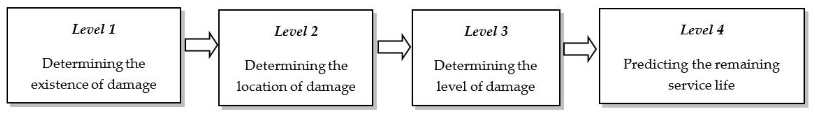
| Changing of natural frequencies | -the ability to easily measure the natural frequency with high accuracy -sensitivity on structural stiffness changes -expected variations of natural frequency can be successfully monitored through the structural health monitoring system -applicable for detection damage existence (Figure 2, level 1) | -impossibility to determine the damage location (global parameter) -sensitivity to environmental effects (temperature change) -difficult to determine the position of the load in symmetrical damages |
| Modal damping change | -the possibility of detecting a nonlinear effect from smeared cracks on the structure -an alternative method in case the natural frequencies and mode shapes are not sufficiently sensitive and reliable -applicable for detection of the damage existence (Figure 2, level 1) | -sensitivity to temperature, load history, etc. -reliability only for simple structures -very complex methods for use in practical application |
| Changing mode shapes | -greater sensitivity in determining the location of damage than natural frequencies -application is possible at level 2 | -requires a large number of sensors -sensitivity to environmental effects during measurement -depends on the completeness of the measured degrees of freedom -weakly sensitive method to small change in stiffness |
| Changing the curvature of mode shapes | -accuracy in determining the location of damage -only experimental data are sufficient -proven reliability on real construction (bridge) | -less sensitive to multiple damages -the need for a large number of sensors -efficiency depends on the number of considered modes shapes |
| Changing modal flexibility | -direct determination of the flexibility matrix from experimental research -sufficient reliability with the use of only the first few modal forms in the calculation -much more sensitive than mode shapes and natural frequencies | -unreliability in determining the locations of multiple damages -requires a large number of sensors for more accurate determination of modal shapes |
| Category | Determination of Corrosion in Reinforced Concrete Elements Analysis of Dynamic Parameters | Literature Review |
|---|---|---|
| By applying basic dynamic parameters | Changing the natural frequency | [10,50,51,52,53,54,55,56,57,58,59,60] |
| Change in damping coefficient | [51,52,53,55,56] | |
| Changing modal shapes | [52] | |
| By applying deviation of basic dynamic parameters | Changing the curvature of modal shapes | - |
| Changing modal flexibility | - |
Publisher’s Note: MDPI stays neutral with regard to jurisdictional claims in published maps and institutional affiliations. |
© 2021 by the authors. Licensee MDPI, Basel, Switzerland. This article is an open access article distributed under the terms and conditions of the Creative Commons Attribution (CC BY) license (https://creativecommons.org/licenses/by/4.0/).
Share and Cite
Duvnjak, I.; Klepo, I.; Serdar, M.; Damjanović, D. Damage Assessment of Reinforced Concrete Elements Due to Corrosion Effect Using Dynamic Parameters: A Review. Buildings 2021, 11, 425. https://doi.org/10.3390/buildings11100425
Duvnjak I, Klepo I, Serdar M, Damjanović D. Damage Assessment of Reinforced Concrete Elements Due to Corrosion Effect Using Dynamic Parameters: A Review. Buildings. 2021; 11(10):425. https://doi.org/10.3390/buildings11100425
Chicago/Turabian StyleDuvnjak, Ivan, Ivan Klepo, Marijana Serdar, and Domagoj Damjanović. 2021. "Damage Assessment of Reinforced Concrete Elements Due to Corrosion Effect Using Dynamic Parameters: A Review" Buildings 11, no. 10: 425. https://doi.org/10.3390/buildings11100425