Article

Structural Efficiency of Hollow Reinforced Concrete Beams Subjected to Partial Uniformly Distributed Loading

by
Hadi Naser Ghadhban Al-Maliki
1,
Ali Al-Balhawi
1,*,
Ahmad Jabbar Hussain Alshimmeri
2 and
Binsheng Zhang
3,*
1
Civil Engineering Department, Mustansiriyah University, Baghdad 10047, Iraq
2
Civil Engineering Department, University of Baghdad, Baghdad 10070, Iraq
3
Civil Engineering and Environmental Management Department, School of Computing, Engineering and Built Environment, Glasgow Caledonian University, Glasgow G4 0BA, UK
*
Authors to whom correspondence should be addressed.
Buildings 2021, 11(9), 391; https://doi.org/10.3390/buildings11090391
Submission received: 5 July 2021 / Revised: 11 August 2021 / Accepted: 13 August 2021 / Published: 3 September 2021
(This article belongs to the Collection Advanced Concrete Structures in Civil Engineering)

Abstract

:
Reinforced concrete (RC) beams containing a longitudinal cavity have become an innovative development and advantage for economic purposes of light-weight members without largely affecting their resistance against the applied loads. This type of openings can also be used for maintenance purposes and usage space of communication lines, pipelines, etc. RC beams are primarily loaded in the plane of the members, which are two-dimensional in a plane stress state and the dominant structural behaviours include bending, shear, or combination of both. In the present study, six numerical models of RC beams with and without openings were simulated by using commercial finite element software ANSYS to evaluate the structural behaviours of those beam models under the partial uniformly distributed load. Different parameters were assessed, including opening dimensions and shear reinforcement ratios. The obtained numerical results were analysed and verified and were found very close to those obtained from the experimental investigations in the literature. The increase of shear reinforcement ratio could enhance the flexural and shear capacities of the RC beams, and the results also showed that some models sustained flexural failure while the others sustained failure of combined bending and shear.

1. Introduction

For decades, concrete has been used widely around the world as a key construction material due to many reasons, including the availability of its raw ingredients, good durability and less required maintenance after construction, the reasonable construction cost, and high mechanical properties in terms of compressive strength in comparing with other materials, e.g., steel and timber. However, concrete has a lower resistance against tensile forces and is heavy. Therefore, it can be used in combination with steel bars to resist external forces based on its own high compressive strength and the high tensile strengths of the latter [1,2], whereas the heavy self-weight of concrete can be compensated by adopting various solutions, e.g., using composite materials, lightweight and recycled aggregates [3,4,5,6,7]. Moreover, openings on the cross-sections of the structural RC members like beams can be used to largely reduce their self-weights [2,8].
Further, for aesthetic, economic, and functional purposes including leaving spaces for mechanical and electrical supply lines, computer networks, water and sewage pipelines, and reducing member weight to save materials, the openings in RC beams and slabs have become popular in the construction of buildings, bridges, offshore structures, and towers [9,10,11,12]. Many studies have considered various configurations of web openings in RC beams [12,13,14,15,16,17,18,19,20,21,22,23,24,25]. However, other studies have investigated structural behaviours of RC beams with longitudinal openings [8,9,10,11,26,27,28,29,30,31,32,33,34,35,36,37,38,39], and these studies are related to the current study and can be divided into two big groups, i.e., experimental and numerical studies in a chronological order.

1.1. Experimental Studies

In 2006, Altun et al. [26] experimentally investigated the flexural performance of classic steel fibre reinforced concrete (SFRC) box beams subjected to bending and explored the effects of reduced dead weight, varied thicknesses, and different ratios of the wall thickness to the beam height on the ultimate load capacity of the beams. They stated that a reduction of 44% in the beam weight could lead to the decrease of the ultimate load carrying capacity by 29%. In 2008, Al-Nuaimi et al. [9] experimentally explored solid and hollow reinforced concrete beams and stated that solid beams cracked initially at higher loads than the hollow beams. The hollow beams failed close to the designated loads, while the solid beams failed at higher loading levels. This indicates that the core space can influence the ultimate load resistance of the section in terms of bending, shear, and torsion.
In 2014, Alshimmeri and Al-Maliki [27] experimentally investigated the behaviours of solid and hollow RC beams subjected to partial uniformly distributed load and explored the influence of vertical shear steel reinforcement and the size and direction of the openings on the flexural behaviour of the beams in terms of the ultimate load capacity, deflection, and ductility. They stated that as the opening size in the beams increased, the ultimate load capacity decreased from 37.14% to 58.33% for the increased cross-section opening ratio of the beams from 7.4% to 14.8%, respectively, while the corresponding deflection increased from 71.6% to 75.5%. On the other hand, the increase in shear reinforcement ratio led to the enhancement of the ultimate load capacity.
The ductility of hollow RC beams increases when the opening ratio decreases and the shear steel reinforcement increases. In 2015, Al-Gasham [28] investigated the effect of installing a PVC pipe inside a RC beam on the behaviour of the reinforced concrete deep beams and indicated that the pipe diameter below 1/3 of the beam width had limited effect on the capacity and rigidity of the beams. For larger pipe diameters, the ultimate load carrying capacities of the beams decreased by 16.7% to 33.3% and the stiffnesses of the beams decreased by 103% to 297%.
Similarly, Murugesan and Narayanan [29] experimentally examined the effect of longitudinal circular hole on the flexural performance of RC beams subjected to four-point bending. The studied parameters were the sizes and positions of holes, while other parameters remained unchanged, e.g., shear span to depth ratio, longitudinal and transverse steel reinforcement ratios, concrete grade, and cross-sectional area. They stated that the failure mode was flexural failure for all hollow RC beams. Moreover, they developed a theoretical equation for predicting the flexural strength and first cracking load of hollow RC beams. In the following study, Murugesan and Narayanan [30] evaluated the behaviour of the previously studied beams in terms of the maximum deflection at different loading stages before and after initial cracks and stated that the developed theoretical formulas would be able to reasonably predict the maximum deflection at different stages.
Al-Khuzaie and Atea [31] investigated the effect of adding steel fibres and silica fume in the concrete on the structural behaviour of hollow RC T-beams subjected to pure torsion and found that the addition of these contents to the concrete could enhance the cracking and ultimate torques for the investigated beams.
Hassan et al. [8] experimentally explored the torsional behaviour of hollow RC beams strengthened with different types of fibres subjected to pure torsional loading and indicated that the used types and lengths of fibres improved the initial cracking load and ultimate load capacity of the beams. Balaji and Vetturayasudharsanan [11] experimentally investigated the flexural performance of hollow RC beams subjected to four-point bending by utilising two types of pipes to create a longitudinal opening in the beams. The investigated parameters included crack pattern, deflection, initial cracking load and ultimate load. Abbass et al. [32] investigated the flexural behaviours of solid and hollow RC beams subjected to four-point bending, and the studied parameters included the addition of steel fibres, the percentage reduction in the void size, the longitudinal reinforcement ratio and the use of lateral stirrups. They found that the hollow RC beams with 1% steel fibre content and a size reduction by 45% due to the opening could be used to replace solid beams, without huge declines in the strength, ductility, and toughness of the beams.
Hassan [33] and Hassan et al. [34] experimentally investigated the behaviour of hollow RC beams with different locations of openings subjected to two concentrated loads and indicated that the opening locations highly affected both the ultimate failure loads and stiffnesses. The tested hollow beams possessed reduced stiffnesses and increased deflections. Moreover, these beams sustained reduced load carrying capacities and ductility index values. El-Kassas et al. [35] experimentally examined the effect of longitudinal openings on the structural behaviours of RC deep beams by varying the location, size, and shape of openings. In general, the load capacity of the beams decreased due to the direct effects of openings. The shapes of openings had insignificant effects on the behaviour of the beams, while the position of the openings had an effective role in governing the structural behaviour of the beams.
Vijayakumar and Madhavi [36] experimentally studied the behaviour of hollow RC beams strengthened with different types of fibres and indicated that with a specified content of the used fibres, the loading capacity of the hollow beams was significantly enhanced under both compression and flexure.

1.2. Numerical Studies

In 2005, Al-Nuaimi and Bhatt [37] experimentally and numerically investigated the behaviours of hollow RC beams subjected to combined bending, shear and torsion and stated that the proposed numerical model had a good ability to predict the experimental results. Hauhnar et al. [38] experimentally and numerically investigated the effect of circular openings in the flexural area on the behaviour of RC beams strengthened with steel pipes and indicated that the differences in the experimental and numerical results were only below 10%. Hassan et al. [10] experimentally and numerically investigated the effect of inserting a PVC pipe in the tension zone of RC beams subjected to four-point bending on the structural behaviour of the beams in terms of cracking and ultimate loads, crack patterns, failure modes, stiffness, deflection, absorbed energy, and ductility index. They stated that for pipe diameters larger than a quarter of the beam width, the ultimate capacities of the RC beams were affected by the locations of the pipes. Moreover, the failure modes for the hollow RC beams were diagonal shear failure. They also used commercial Finite Element Method (FEM) software ANSYS to predict the failure load and calibrate the experimental behaviours of the tested beams. Elamary et al. [39] experimentally and numerically investigated the structural performance of hollow RC beams with varied areas and locations of hollow cores subjected to three-point loading. They indicated that core areas below 10% of the cross-section areas had a negligible effect on the failure loads of these beams, while the openings had an effect of worsening the crack patterns including crack sizes and heights. They also carried out numerical simulations to predict the behaviours of the tested beams and also conducted a parametric study on the effect of locations and sizes of the adopted openings.

1.3. Significance of the Study

Most of the studies mentioned above have experimentally investigated the structural behaviours of hollow RC beams. However, there is a lack of numerical investigations on the structural behaviours of hollow RC beams in literature with considering numerous aspects and calibrating the numerical results with the experimental ones. Therefore, this study numerically examined the structural performance of previously tested hollow RC beams in the literature [27]. Moreover, the main aim of the present study was to explore the overall structural performance and efficiency of hollow RC beams with longitudinal openings subjected to partial distributed load using ANSYS [40]. This finite element analysis software was used to simulate and analyse the behaviours of all tested beams and could provide a reliable method for numerically predicting the experimental results. Further, the structural behaviours of these beam models including the load capacity, cracking pattern, deflection, and failure mode were evaluated and analysed.

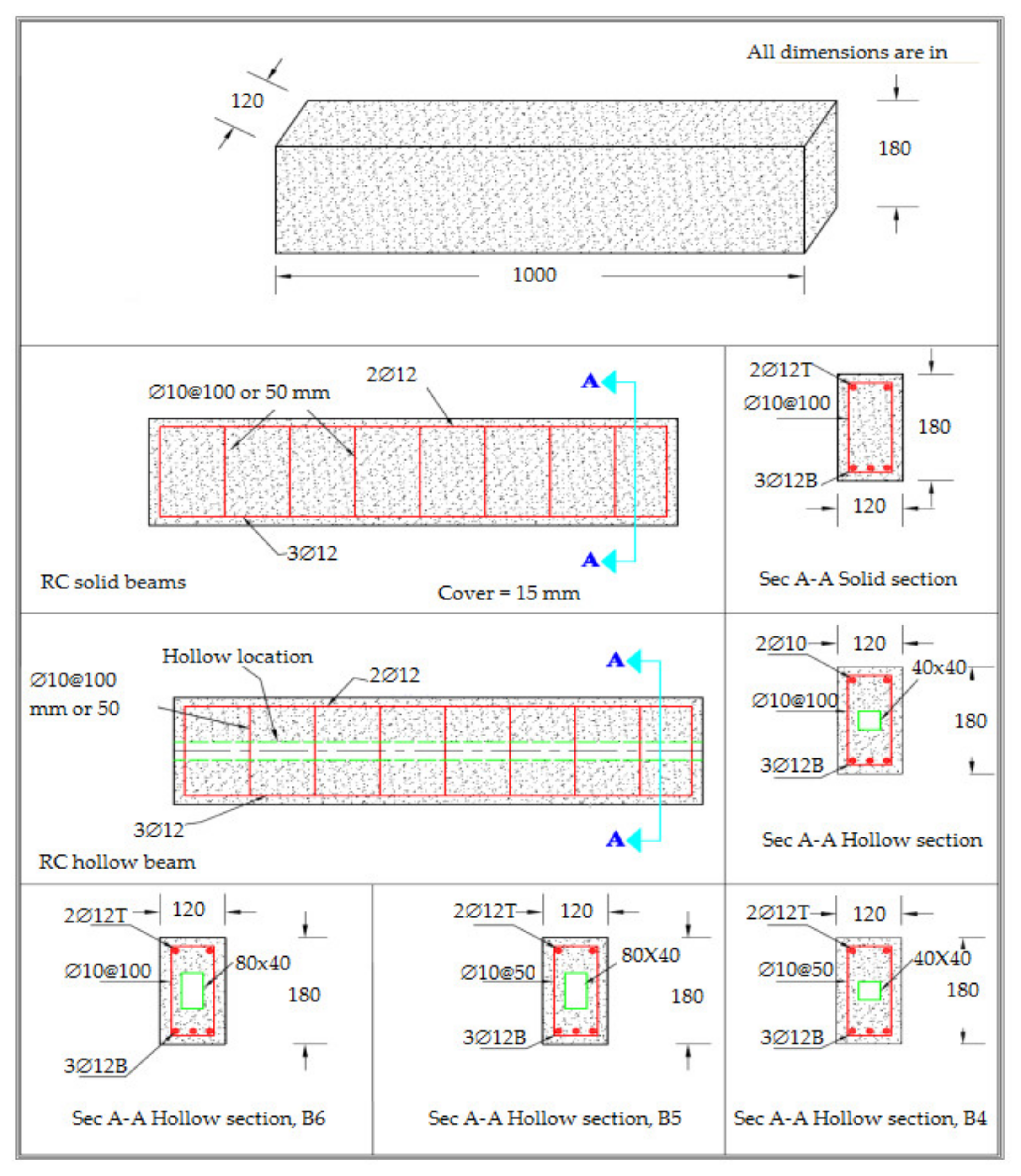
2. Geometric Configurations of the Numerical Models

All RC beam models were simulated depending on the previous experimental test results [27]. The loads, support conditions, and geometric dimensions of the hollow cores from the experimental results were applied to the numerical models. All numerical beam models had the same dimensions of 1000 mm × 120 mm × 180 mm. Table 1 lists the parameters for the numerical beam models, and Figure 1 illustrates the geometry, layout, reinforcements, and core details for all beam models.

3. Mechanical Properties of the Concrete and Steel Materials

The mechanical properties of the used materials including concrete and reinforcements with no hardening, as reported by Alshimmeri and Al-Maliki [27], are indicated in Table 2 and Table 3, respectively. The concrete properties include the compressive strength fc′, the tensile strength ft, the modulus of rupture fr, the elastic modulus Ec, and the Poisson’s ratio vc. The steel properties include the bar diameter Ø, the yield strength fy, the ultimate tensile strength fu, the elastic modulus Es, and the Poisson’s ratio vs. These properties were required as the inputs in the ANSYS [40].

4. Numerical Analysis Approach

4.1. Assumptions

In the numerical analyses of the RC beams, the reinforcements and surrounding concrete were assumed to be isotropic and homogeneous materials and had the same connection nodes without frictions between the two materials, i.e., discrete simulations of reinforcements. The plane sections were assumed to remain plane in elastic behaviour, and there were no geometric deviations due to nonlinearity. The stress–strain relationships for all reinforcements were assumed to be elastic-perfectly plastic.
The average load capacities were taken from the previous experimental study [27] and compared with the numerical results using the finite element software ANSYS [40]. The numerical model contained numerous small elements, e.g., 40, 6, and 8 elements in the length, width, and depth directions, respectively. The connections between rebar nodes were similar to those of the concrete solid nodes. Therefore, the concrete and steel reinforcement nodes were merged. This technique would provide the perfect bond between the reinforcements and the surrounding concrete. A tolerance of 0.05 was adopted when using displacement control during the nonlinear iterations for convergence. Moreover, the full structural behaviours of the controlled hollow RC beams and other specimens under partial distributed static loading conditions were explored.

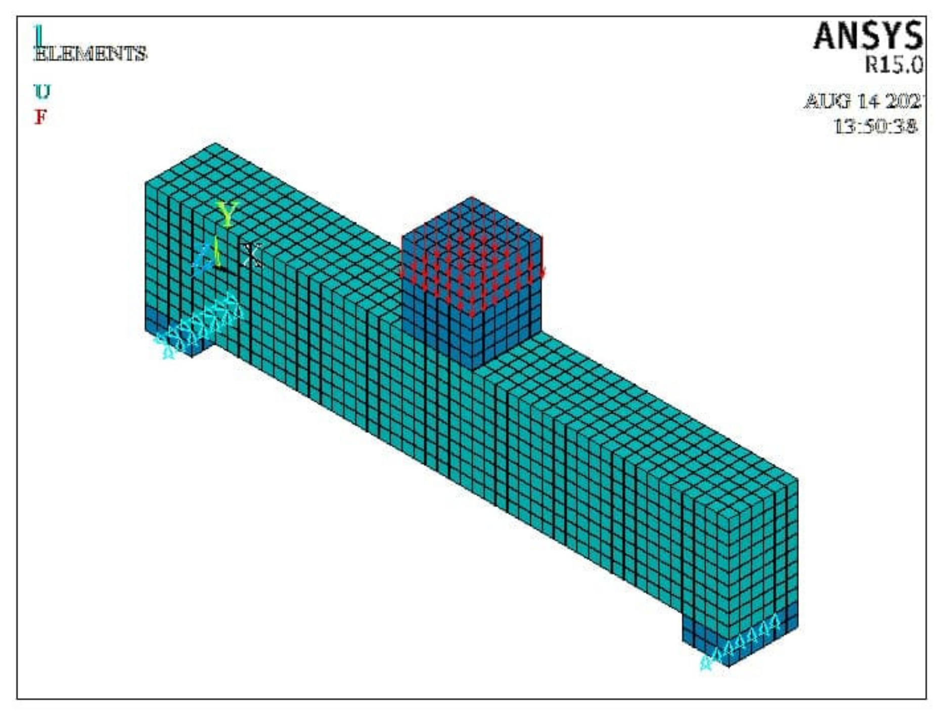
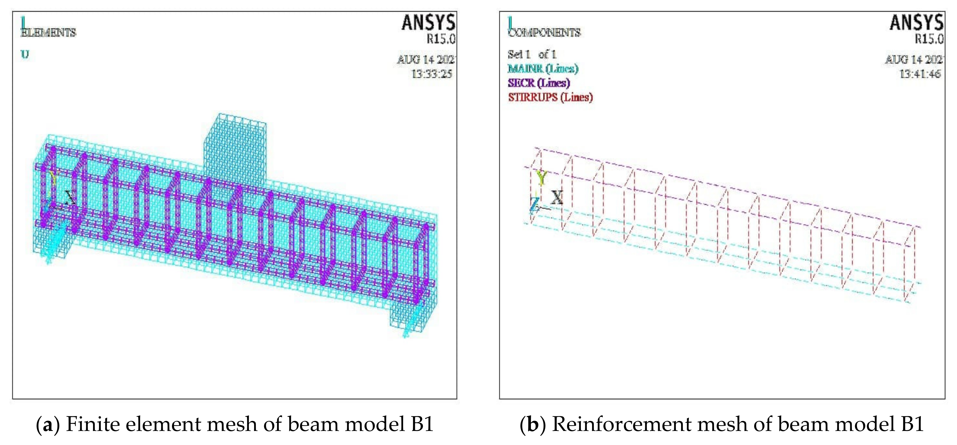
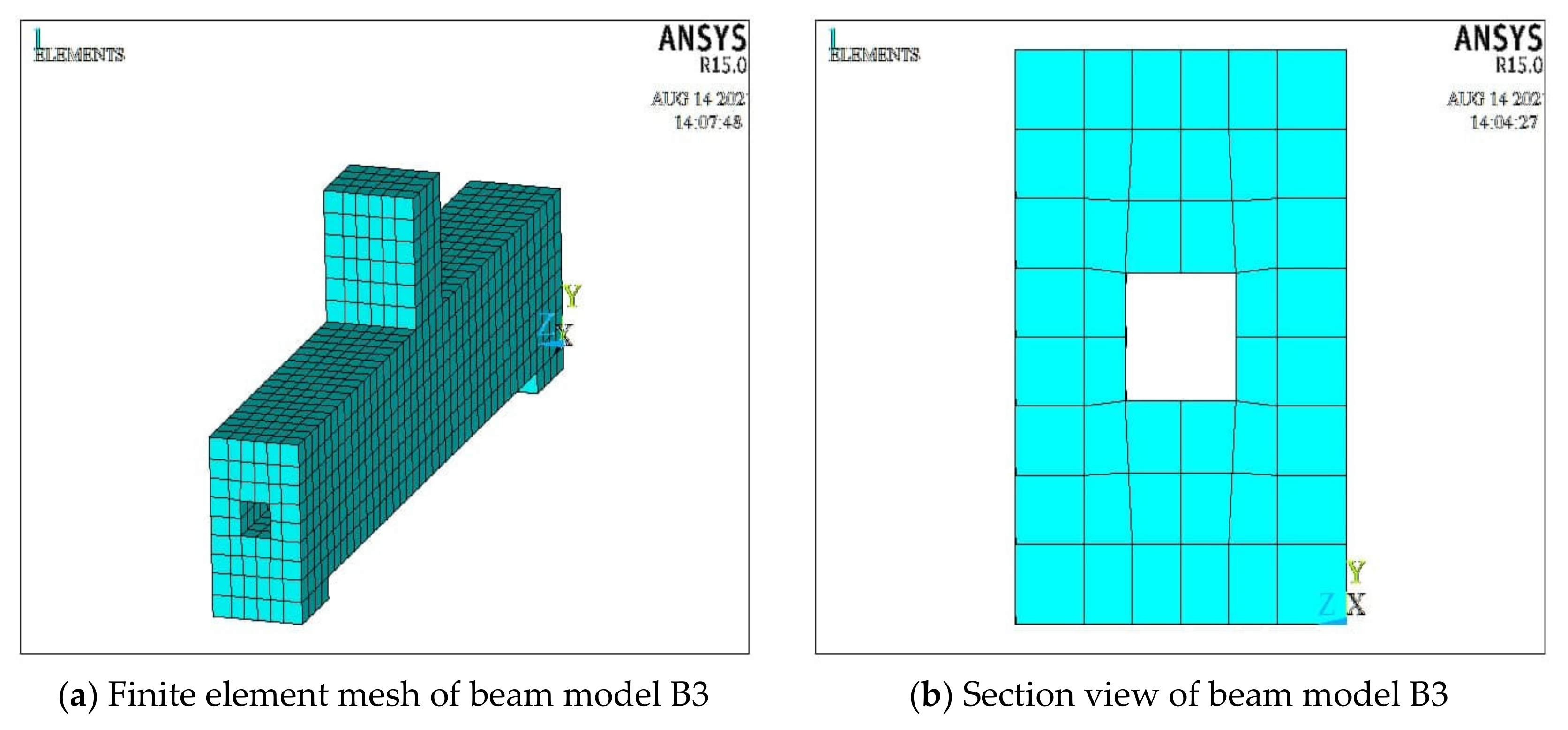
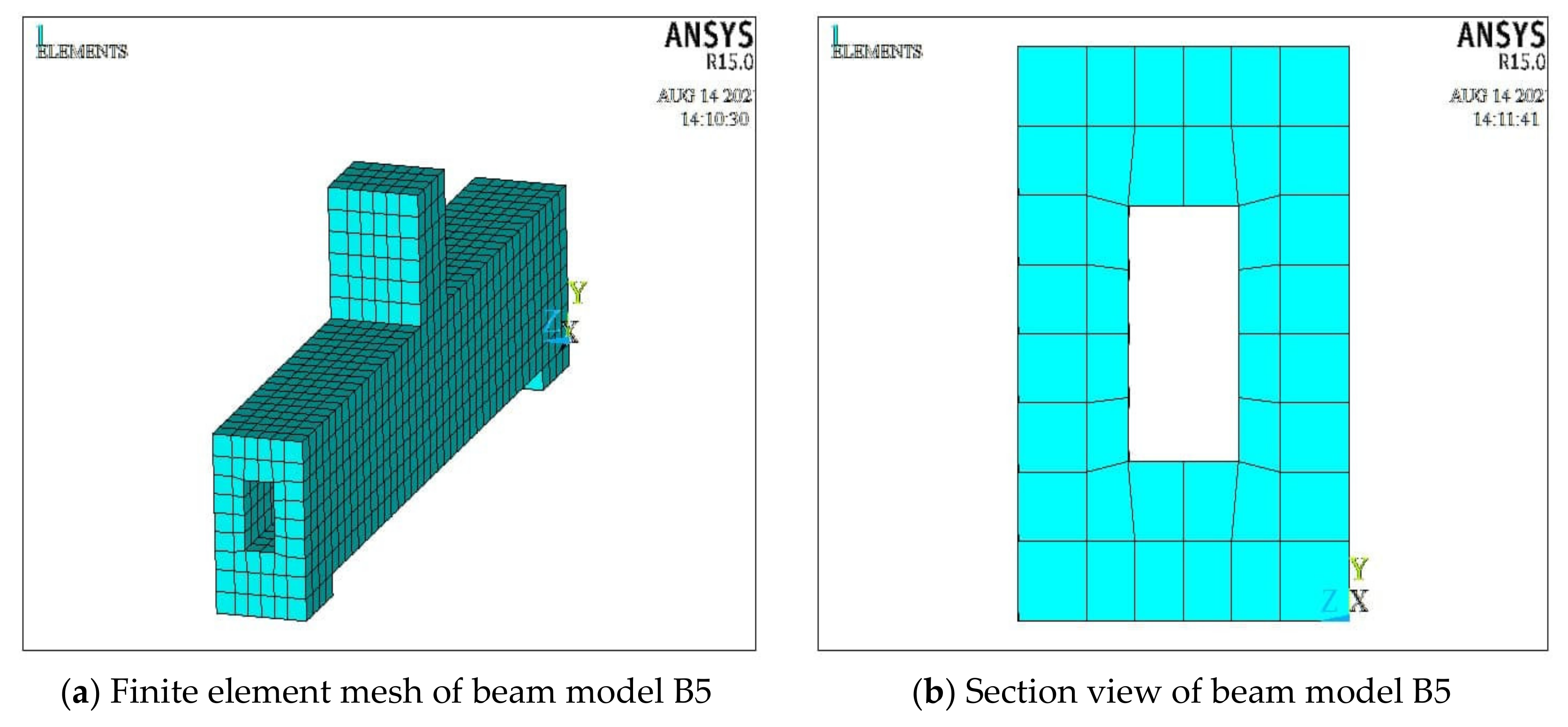
4.2. Numerical Modelling Using Finite Element Software ANSYS

Numerical analyses were conducted by using ANSYS [40] to simulate all hollow RC beams including the control model. Different elements were selected to simulate the actual behaviours of concrete, plate supports, plate elements under loads, main reinforcements, and stirrups. SOLID65 elements were selected for concrete materials with three degrees of freedom at each node in translational directions. LINK180 elements were adopted to simulate all reinforcing steel bars. SOLID185 elements were chosen to represent the steel plates that were located between the applied loads and the RC beams and between the RC beams and supports [27]. The smeared cracking model was the best representation of RC members such as hollow RC beams. The open and close coefficients for concrete cracks were set as 0.2 and 0.7, respectively. The mechanical behaviours of the materials for steel rebars and concrete were assumed to be elastic-perfectly plastic. The stages of behaviour were linear up to 0.3 fc′, elastic up to 0.85 fc′ and fully plastic at fc′ up to the maximum concrete failure strain of 0.003. The main assumption of the numerical analysis was that the plane section would remain plane before and after the applied loads, the concrete was homogeneous, full bonding was maintained between the concrete and reinforcements, and the self-weights of the RC beams were not considered in the analysis by matching the experimental results.
Figure 2 illustrates the 3D view of the element mesh of the control beam model B1, while Figure 3 illustrates the 3D view of the wireframe for the whole beam components including the top and bottom reinforcements and stirrups with simply supported conditions. The left support was a roller, and the right support was a pin, which restrained both horizontal and vertical directions. Figure 4 illustrates the 3D views of the finite element meshes of the beam model B3 and the beam model B4 with the hollow core area ratio of 7.4%, respectively. Similarly, Figure 5 illustrates the 3D view of the finite element mesh of the beam model B5 and the sectional view of the beam model B6 with the hollow core area ratio of 14.8%, respectively.

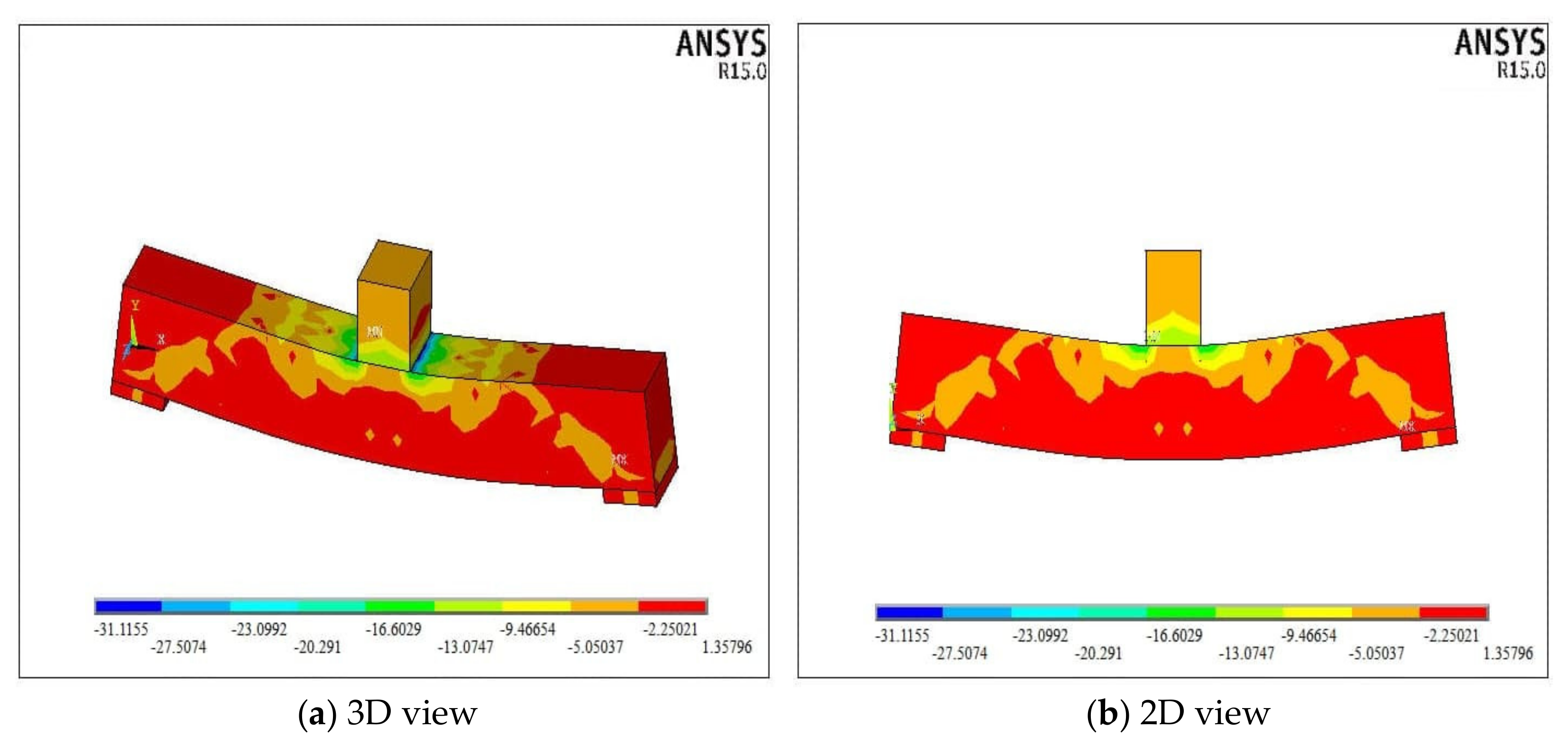
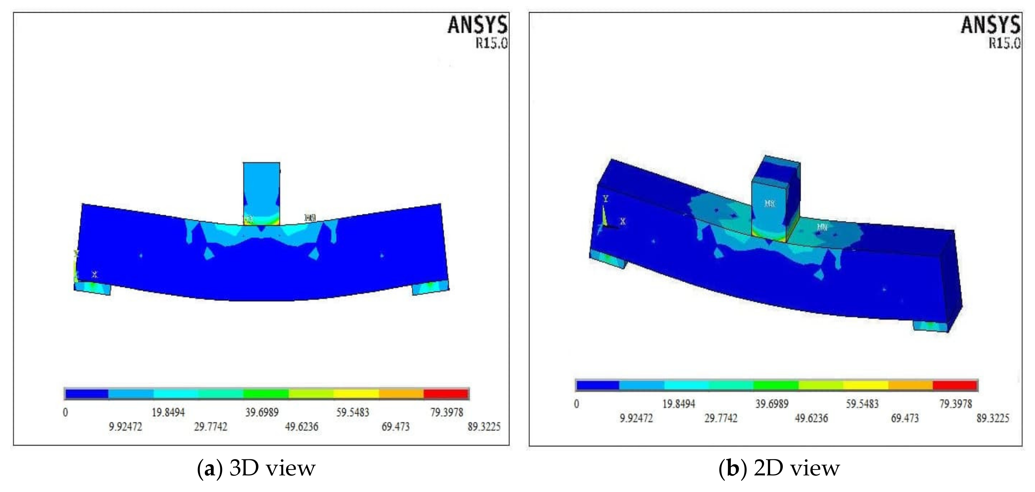
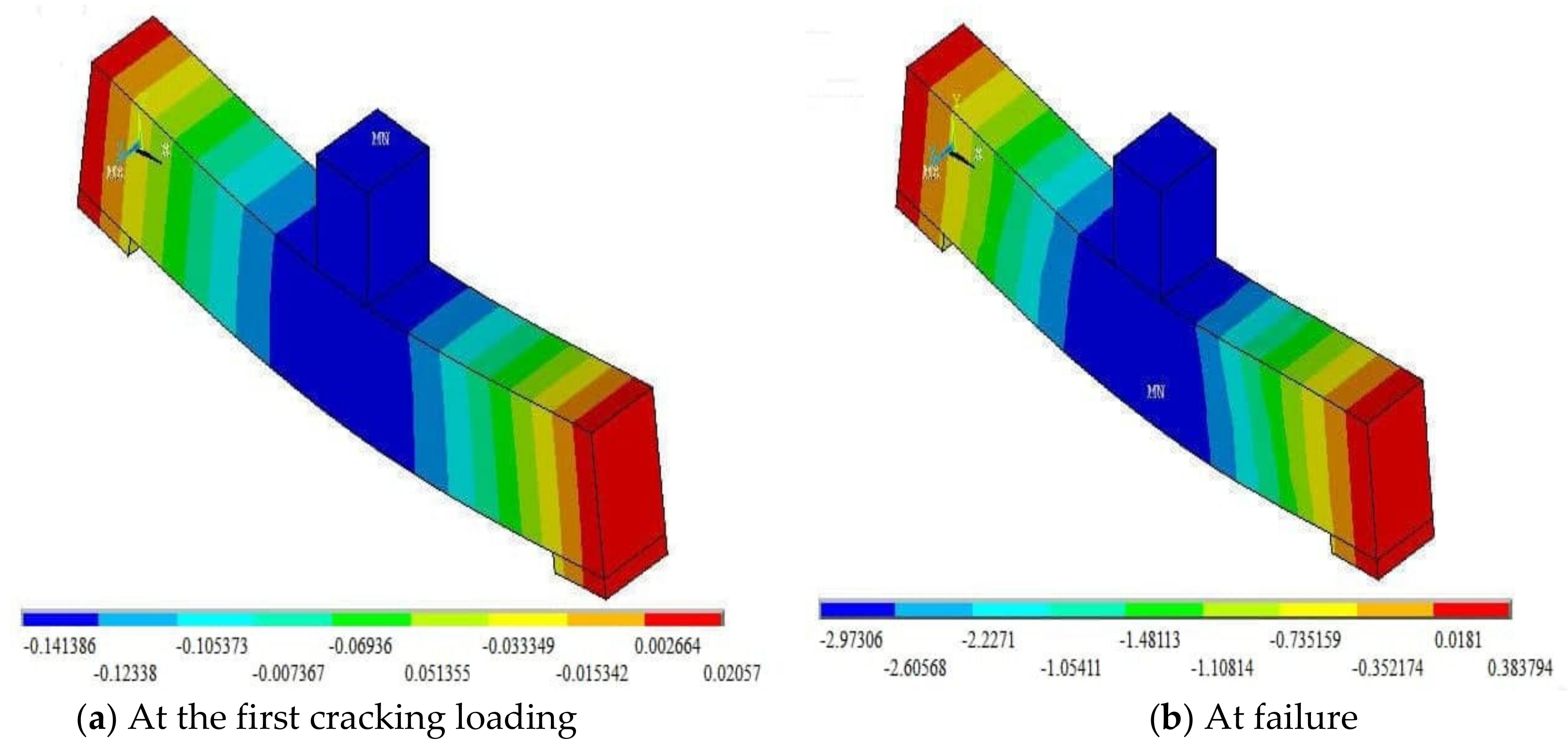
5. Numerical Analysis Results and Discussion

In this section, the obtained numerical results with considering the indicated parameters are presented and discussed. Six finite element beam models were analysed by using ANSYS [40] and quoting the mechanical properties and applied loads from the previous experimental tests [27]. Based on the obtained numerical analysis results, all the beam models failed in shear. Figure 6 illustrates the 3D and 2D hydrostatic stress contours of the control beam B1 at failure where diagonal stresses formed from supports up to the locations of the loading area. Figure 7 and Figure 8 illustrate the 3D and 2D contours for the von Mises stress and strain of the control beam model B1, respectively.
Figure 9, Figure 10, Figure 11, Figure 12, Figure 13 and Figure 14 illustrate the 3D views of the deflection contours of different beam models at the initial cracking load and at failure. The deformed beam models indicate that the maximum deflections occurred in the middle regions underneath the applied loads. The central deflections represent the relative deflections that were recorded from zero values at supports to the middle span regions of the beam models.
Figure 15 illustrates the crack patterns for all the simulated beam models, which are in good agreements with those actual cracking patterns from the experimental tests [27]. The diagonal cracks indicate that the failure mode is shear failure. The first, second, and third cracks of all the numerical beam models indicate that the cracks formed and developed in the hollow RC beams in the length, depth, and thickness directions, respectively. The cracks formed and developed due to the increase in the internal stresses in the tension zones. According to the proposed design equation of American code ACI-318 [41] for the modulus of rupture (fr = 0.62 fc0.5), the concrete crush occurred when the internal stress at the compression zone became larger than the characteristic compressive strength. The cracking intensity became less in cases of increasing the shear reinforcement ratio.
Figure 16, Figure 17 and Figure 18 illustrate the comparisons of the numerical and experimental results of the load-deflection relationships for all the beam models. The first cracking loads differed for individual beam models and relied on the actual resistances to the applied loads. These loads led to the occurrences of the internal stresses of the beam models. When the stresses became larger than the modulus of rupture of concrete, the cracks would propagate. The solid beam model B2 had a 100% larger shear reinforcement area than the beam models B1, B3, and B6. Hence, its ultimate load capacity would also be larger and the load that caused the first crack also became higher due to the increase in the shear resistance in relation to the increase of the shear reinforcement area. All the hollow core beams had smaller load capacities, including both flexural and shear ones. However, when more shear reinforcement area was used for the hollow RC beams, an enhancement in the crack resistance could be achieved, and the structural behaviours of the beam models would be similar to that of the solid beam model. In general, all the beam models showed linear behaviours up to some inflection points that represented the formation of the first cracks. Afterward, the beam models had different nonlinear hardening trends for the loads with deflection, which would cause the reductions in the stiffnesses of the beam models up to failure.
Table 4 shows the comparisons of the numerical results of the mid-span deflections of the beam models at the first cracking load and failure load with those from the experimental investigations [27], together with the means and standard deviations of the ratios of the numerical deflections to the experimental ones. This table also indicates that when the applied load increased, the corresponding deflection increased as well. In addition, the adoption of the hollow cores could increase the deflections along with the applied loads. Table 5 shows the comparisons of the numerical and experimental results of the ductility indexes (DIs) of the beam models, together with the means and standard deviations of the ductility index ratios of the numerical results to the experimental ones. The DI values from the experimental investigations and numerical analyses were very close, with an average of 0.99 for the ductility index ratios. Table 5 also indicates that the deflection ductility index was influenced not only by the presence of hollow cores but also by the applied loading and stirrups spacing. For example, the ductility index for the solid beam model B2 was larger than that of the control solid beam model B1. This is due to the larger applied and failure loads on the solid beam model B2 caused by the different shear reinforcement spacings between the two models. This trend can also be seen through the comparisons between the beam models B1, B2, B3, B4, B5, and B6.

6. Conclusions

Based on the currently conducted numerical simulations on the solid and hollow RC beam models, the following conclusions can be drawn:
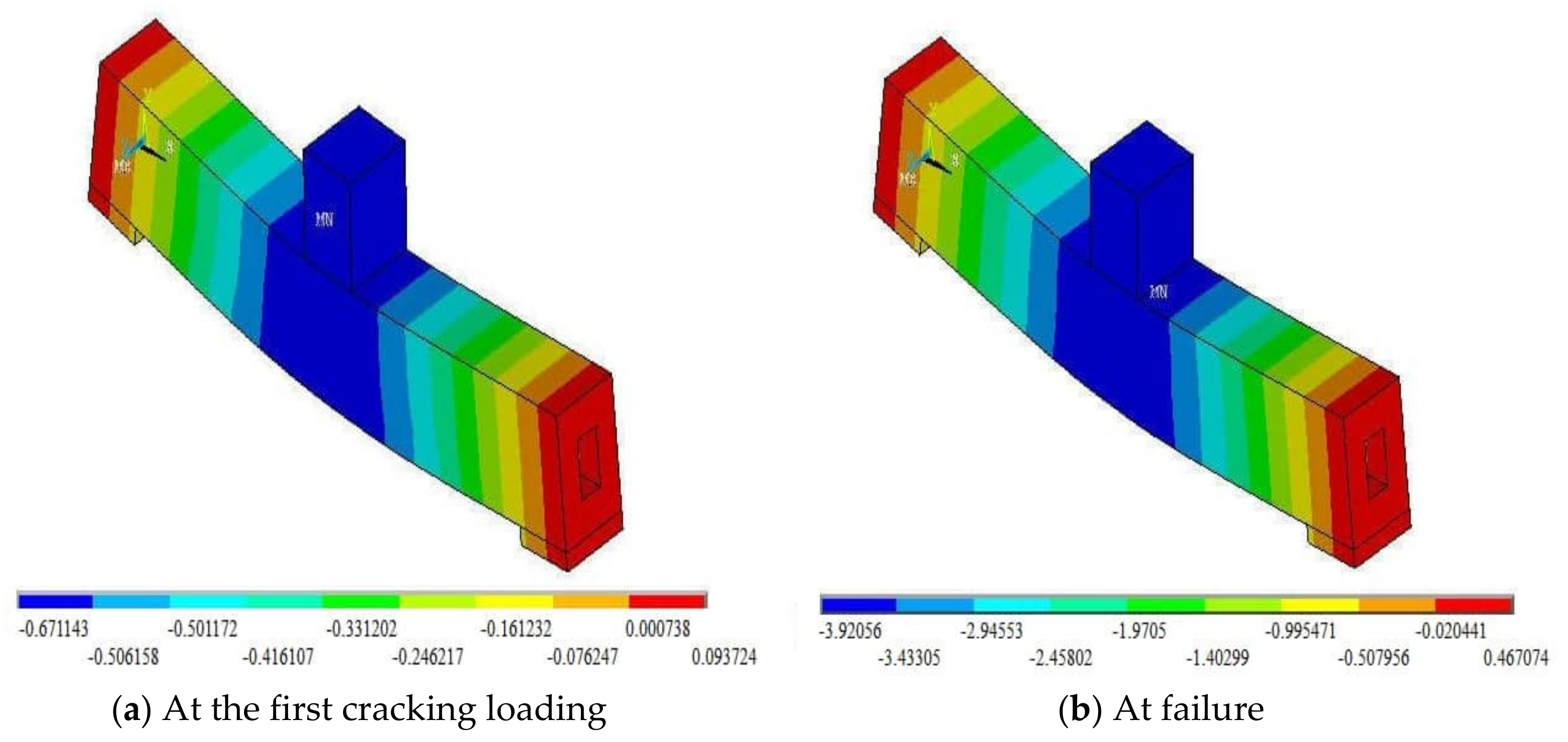
  • The load causing the first crack relied on different influencing factors and was mainly affected by the increase in the vertical shear reinforcement ratio along the length, which would enhance the ductility and stiffness of concrete.
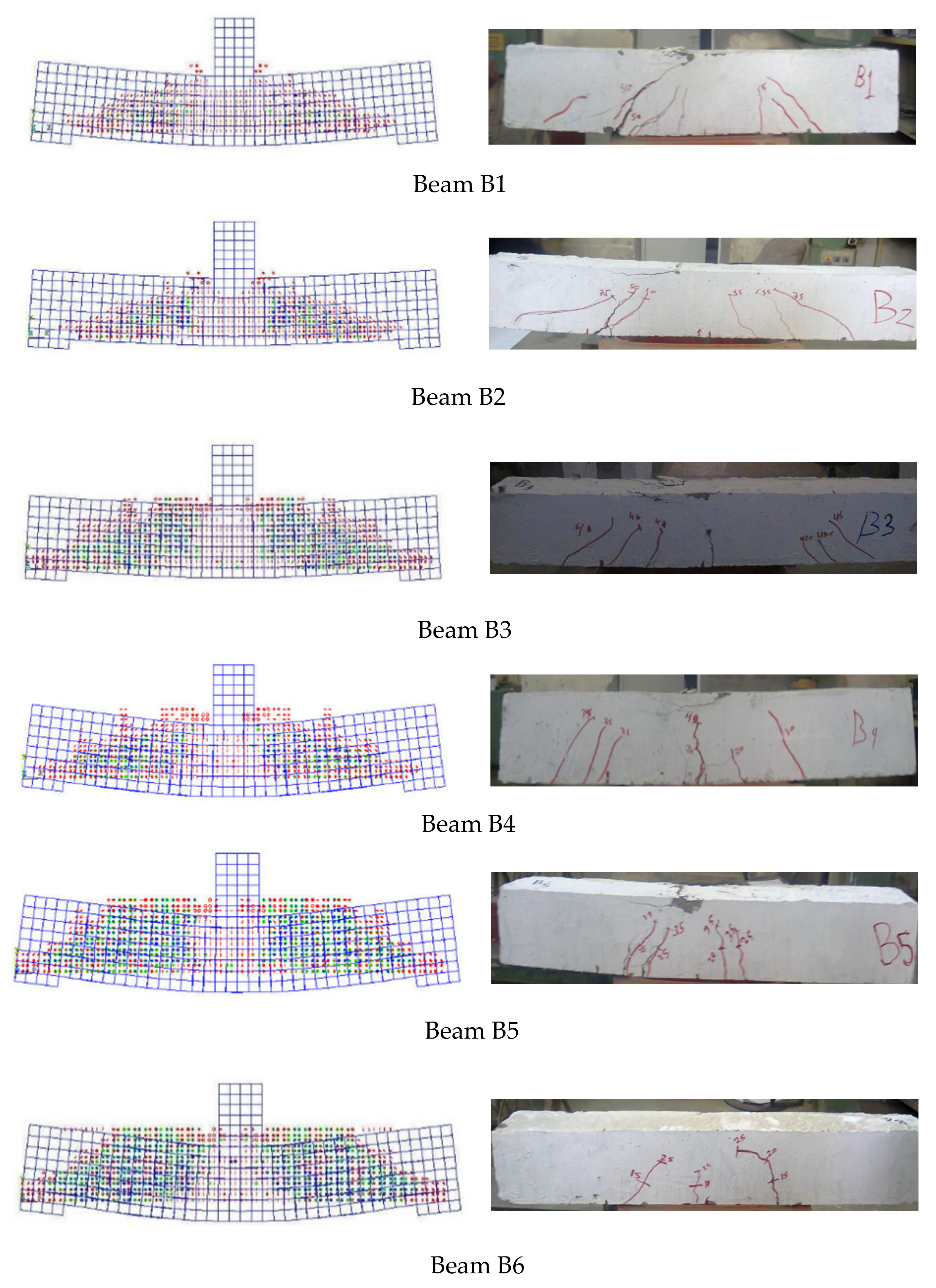
  • All beam models sustained compound failures due to the propagations of shear and flexural cracks.
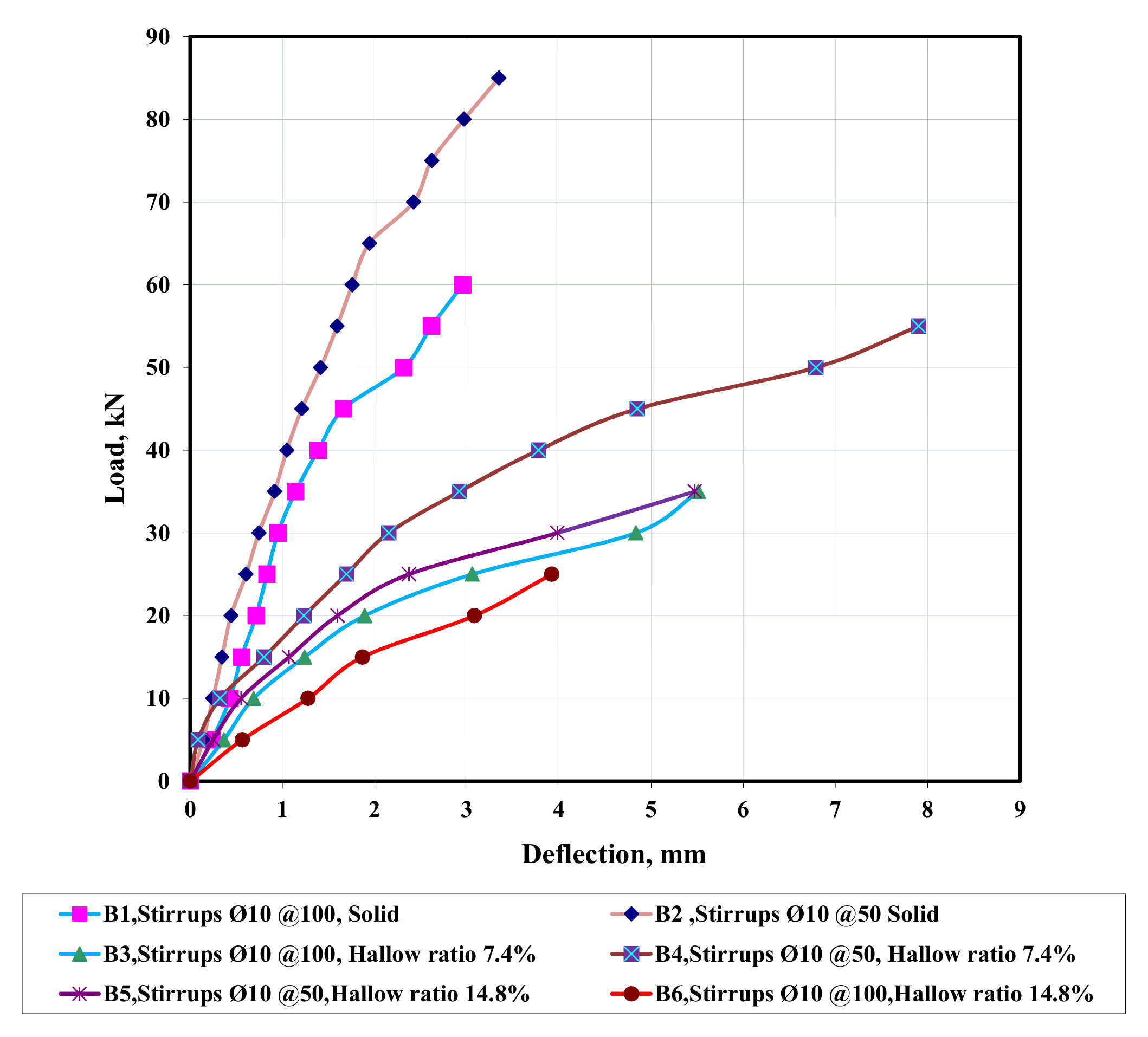
  • The trends of the load-deflection curves varied for the beam models due to the composite actions between concrete and steel reinforcements, causing increases in the equivalent modulus of elasticity and moment of inertia of the beam members, both being the stiffness parameters.
  • The presence of the hollow cores located in the central regions of the reinforced concrete beam models could be considered in the design to reduce the self-weight of RC beams and allow the service utilities to pass through them. The losses in the load capacity due to the presence of the openings could be compensated and enhanced by increasing the vertical shear reinforcement ratio.
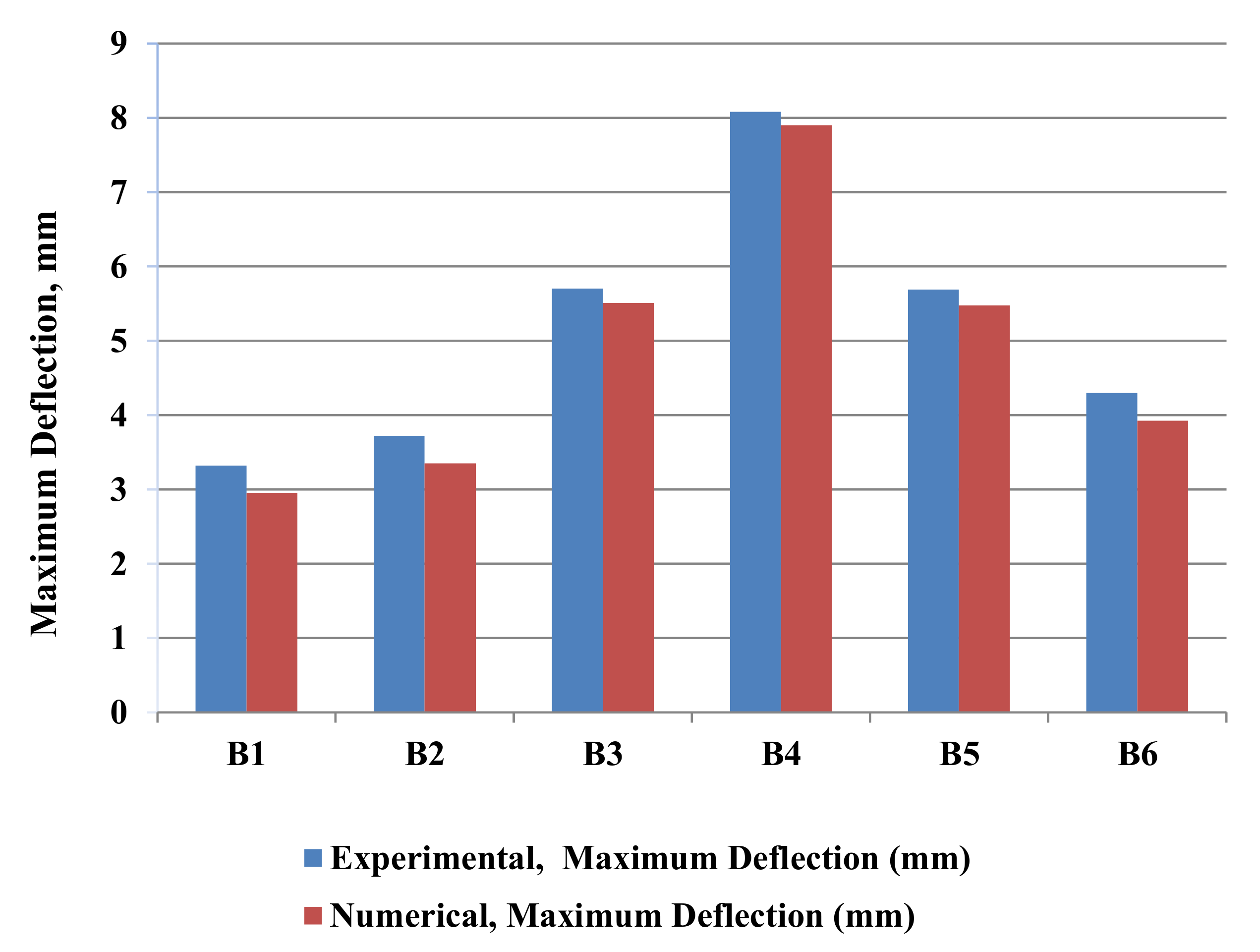
  • The numerical results using finite element method showed excellent agreements with the corresponding experimental results. Therefore, this numerical method could be used to explore and predict the remaining strengths of the RC beams by considering the indicated parameters in this study.
  • The statistical analyses on the mean and standard deviation values of the ductility indices (DIs) for the experimental and numerical deflections at the first cracking load and ultimate load indicated the closely obtained results and confirmed the accuracy of the current numerical simulations.
  • The current study provided the opportunity to develop a further insight on the effects of multilayer steel reinforcements on the load capacity of RC beams, repairing RC beams by using carbon fibre reinforced polymers (CFRPs) to resist the effect of dynamic loading, and utilising the benefit of openings in vertical and transverse directions. The current strategy of simulating RC beams with longitudinal hollow cores could be used as a starting point for analysis and design recommendations for dimensions and locations of hollow cores in RC beams.

Author Contributions

Conceptualization, H.N.G.A.-M.; data curation, H.N.G.A.-M., A.A.-B., A.J.H.A. and B.Z.; formal analysis, H.N.G.A.-M., A.A.-B. and B.Z.; funding acquisition, H.N.G.A.-M., A.A.-B., A.J.H.A. and B.Z.; investigation, H.N.G.A.-M., A.A.-B. and B.Z.; methodology, H.N.G.A.-M., A.A.-B., A.J.H.A. and B.Z.; resources, H.N.G.A.-M., A.A.-B., A.J.H.A. and B.Z.; validation, H.N.G.A.-M., A.A.-B., A.J.H.A. and B.Z.; visualization, H.N.G.A.-M., A.A.-B., A.J.H.A. and B.Z.; writing—original draft, H.N.G.A.-M.; writing—review and editing, A.A.-B. and B.Z. All authors have read and agreed to the published version of the manuscript.

Funding

This research received no external funding.

Data Availability Statement

The data are available from the first author on request.

Acknowledgments

The authors would like to thank Mustansiriyah University, (Available online: https://uomustansiriyah.edu.iq/ accessed on 13 August 2021), Baghdad, Iraq, for its support in the present work. The first and second authors are very grateful for the cooperation with the University of Baghdad in Iraq and Glasgow Caledonian University in Scotland, UK.

Conflicts of Interest

The authors declare no conflict of interest.

References

  1. Al-Balhawi, A. Dynamic Responses of Tall Reinforced Concrete Buildings Subjected to Wind Loading. Ph.D. Thesis, Glasgow Caledonian University, Glasgow, UK, 2018. [Google Scholar]
  2. Abbass, A.; Abid, S.; Özakça, M. Experimental investigation on the effect of steel fibers on the flexural behavior and ductility of high-strength concrete hollow beams. Adv. Civ. Eng. 2019, 2019, 8390345. [Google Scholar] [CrossRef]
  3. Katzer, J. Strength performance comparison of mortars made with waste fine aggregate and ceramic fume. Constr. Build. Mater. 2013, 47, 1–6. [Google Scholar] [CrossRef]
  4. Abid, S.R.; Nahhab, A.H.; Al-Aayedi, H.K.; Nuhair, A.M. Expansion and strength properties of concrete containing contaminated recycled concrete aggregate. Case Stud. Constr. Mater. 2018, 9, e00201. [Google Scholar] [CrossRef]
  5. Wang, J.; Xiao, Z.; Zhu, C.; Feng, C.; Liu, J. Experiment on the bonding performance of the lightweight aggregate and normal weight concrete composite beams. Case Stud. Constr. Mater. 2021, 15, e00565. [Google Scholar] [CrossRef]
  6. Horňáková, M.; Lehner, P. Relationship of surface and bulk resistivity in the case of mechanically damaged fibre reinforced red ceramic waste aggregate concrete. Materials 2020, 13, 5501. [Google Scholar] [CrossRef] [PubMed]
  7. Omar, A.T.; Hassan, A.A.A. Behaviour of expanded slate semi-lightweight SCC beams with improved cracking performance and shear capacity. Structures 2021, 32, 1577–1588. [Google Scholar] [CrossRef]
  8. Hassan, R.F.; Jaber, M.H.; Al-Salim, N.H.; Hussein, H.H. Experimental research on torsional strength of synthetic/steel fiberreinforced hollow concrete beam. Eng. Struct. 2020, 220, 110948. [Google Scholar] [CrossRef]
  9. Al-Nuaimi, A.S.; Al-Jabri, K.S.; Hago, A. Comparison between solid and hollow reinforced concrete beams. Mater. Struct. 2008, 41, 269–286. [Google Scholar] [CrossRef]
  10. Hassan, N.Z.; Ismael, H.M.; Salman, A.M. Study behavior of hollow reinforced concrete beams. Int. J. Curr. Eng. Technol. 2018, 6, 1640–1651. [Google Scholar] [CrossRef]
  11. Balaji, G.; Vetturayasudharsanan, R. Experimental investigation on flexural behaviour of RC hollow beams. Mater. Today Proc. 2020, 21, 509–516. [Google Scholar] [CrossRef]
  12. Hemzah, S.A.; Alyhya, W.S.; Hassan, S.A. Experimental investigation for structural behaviour of self-compacting reinforced concrete hollow beams with in-place circular openings strengthened with CFRP laminates. Structures 2020, 24, 99–106. [Google Scholar] [CrossRef]
  13. Mansur, M.A. Effect of openings on the behaviour and strength of R/C beams in shear. Cem. Concr. Compos. 1998, 6, 477–486. [Google Scholar] [CrossRef]
  14. Abdalla, H.A.; Torkey, A.M.; Haggag, H.A.; Abu-Amira, A.F. Design against cracking at openings in reinforced concrete beams strengthened with composite sheets. Compos. Struct. 2003, 2, 197–204. [Google Scholar] [CrossRef]
  15. Amiri, J.V.; Bygie, M.H. Effect of small circular opening on the shear and flexural behavior and ultimate strength of reinforced concrete beams using normal and high strength concrete. In Proceedings of the 13th World Conference on Earthquake Engineering, Vancouver, BC, Canada, 1–6 August 2004. [Google Scholar]
  16. Yang, K.H.; Eun, H.C.; Chung, H.S. The influence of web openings on the structural behavior of reinforced high-strength concrete deep beams. Eng. Struct. 2006, 13, 1825–1834. [Google Scholar] [CrossRef]
  17. Aykaç, S.; Yilmaz, M.C. Behaviour and strength of RC beams with regular triangular or circular web openings. J. Fac. Eng. Archit. Gazi Univ. 2011, 3, 711–718. [Google Scholar]
  18. Ahmed, A.; Fayyadh, M.M.; Naganathan, S.; Nasharuddin, K. Reinforced concrete beams with web openings: A state of the art review. Mater. Des. 2012, 40, 90–102. [Google Scholar] [CrossRef]
  19. Mahmoud, A.M. Strengthening of concrete beams having shear zone openings using orthotropic CFRP modeling. Ain Shams Eng. J. 2012, 3, 177–190. [Google Scholar] [CrossRef] [Green Version]
  20. Aykac, B.; Aykac, S.; Kalkan, I.; Dundar, B.; Can, H. Flexural behavior and strength of reinforced concrete beams with multiple transverse openings. ACI Struct. J. 2014, 2, 267–277. [Google Scholar]
  21. Jabbar, S.; Hejazi, F.; Mahmod, H.M. Effect of an opening on reinforced concrete hollow beam web under torsional, flexural, and cyclic loadings. Lat. Am. J. Solids Struct. 2016, 8, 1576–1595. [Google Scholar] [CrossRef] [Green Version]
  22. Nie, X.F.; Zhang, S.S.; Teng, J.G.; Chen, G.M. Experimental study on RC T-section beams with an FRP-strengthened web opening. Compos. Struct. 2018, 185, 273–285. [Google Scholar] [CrossRef]
  23. Majeed, Q.G.; Ahmed, Q.W.; Mohammed, A.H.; Sammen, S.S. Experimental study of reinforced concrete beams with elliptical opening under flexural loading. IOP Conf. Ser. Mater. Sci. Eng. 2020, 1, 1–10. [Google Scholar] [CrossRef]
  24. Jabbar, D.N.; Al-Rifaie, A.; Hussein, A.M.; Shubbar, A.A.; Nasr, M.S.; Al-Khafaji, Z.S. Shear behaviour of reinforced concrete beams with small web openings. Mater. Today Proc. 2021, 5, 2713–2716. [Google Scholar] [CrossRef]
  25. Salih, R.; Abbas, N.; Zhou, F. Experimental and Numerical investigations on the cyclic load behavior of beams with rectangular web openings strengthened using FRP sheets. Structures 2021, 33, 655–677. [Google Scholar] [CrossRef]
  26. Altun, F.; Haktanir, T.; Ari, K. Experimental investigation of steel fiber reinforced concrete box beams under bending. Mater. Struct. 2006, 4, 491–499. [Google Scholar] [CrossRef]
  27. Alshimmeri, A.J.H.; Al-Maliki, H.N.G. Structural behavior of reinforced concrete hollow beams under partial uniformly distributed load. J. Eng. 2014, 7, 130–145. [Google Scholar]
  28. Al-Gasham, T.S.S. Reinforced concrete moderate deep beams with embedded PVC pipes. Wasit J. Eng. Sci. 2015, 1, 19–29. [Google Scholar] [CrossRef]
  29. Murugesan, A.; Narayanan, A. Influence of a longitudinal circular hole on flexural strength of reinforced concrete beams. Pract. Period. Struct. Des. Constr. 2017, 22, 04016021. [Google Scholar] [CrossRef]
  30. Murugesan, A.; Narayanan, A. Deflection of reinforced concrete beams with longitudinal circular hole. Pract. Period. Struct. Des. Constr. 2018, 23, 04017034. [Google Scholar] [CrossRef]
  31. Al-Khuzaie, H.M.A.; Atea, R.S. Investigation of torsional behavior and capacity of reactive powder concrete (RPC) of hollow T-beam. J. Mater. Res. Technol. 2019, 1, 199–207. [Google Scholar] [CrossRef]
  32. Abbass, A.A.; Abid, S.R.; Arna’ot, F.H.; Al-Ameri, R.A.; Ozakca, M. Flexural response of hollow high strength concrete beams considering different size reductions. Structures 2020, 23, 69–86. [Google Scholar] [CrossRef]
  33. Hassan, S.A. Structural Behaviour of Self-Compacted Concrete Box Girders with In-Place Openings. Master’s Thesis, University of Kerbala, Kerbala, Iraq, 2020. [Google Scholar]
  34. Hassan, S.A.; Hemzah, S.A.; Alyhya, W.S. Experimental investigation of the structural behaviours of self-compacted reinforced concrete hollow beams with inplace circular openings. IOP Conf. Ser. Mater. Sci. Eng. 2020, 671, 1–10. [Google Scholar] [CrossRef]
  35. El-Kassas, A.I.; Hassan, H.M.; Arab, M.A.E.S. Effect of longitudinal opening on the structural behavior of reinforced high-strength self-compacted concrete deep beams. Case Stud. Constr. Mater. 2020, 12, e00348. [Google Scholar] [CrossRef]
  36. Vijayakumar, A.; Madhavi, T.C. Behaviour of self compacting concrete with hybrid fibers in hollow beams. Mater. Today Proc. 2021, 46, 3212–3219. [Google Scholar] [CrossRef]
  37. Al-Nuaimi, A.S.; Bhatt, P. 2D idealisation of hollow reinforced concrete beams subjected to combined torsion, bending and shear. J. Eng. Res. 2005, 1, 53–68. [Google Scholar] [CrossRef] [Green Version]
  38. Hauhnar, L.; Rajkumar, R.; Umamaheswari, N. Behavior of reinforced concrete beams with circular opening in the flexural zone strengthened by steel pipes. Int. J. Civ. Eng. Technol. 2017, 5, 303–309. [Google Scholar]
  39. Elamary, A.S.; Sharaky, I.A.; Alqurashi, M. Flexural behaviour of hollow concrete beams under three points loading: Experimental and numerical study. Structures 2021, 32, 1543–1552. [Google Scholar] [CrossRef]
  40. ANSYS, Inc. ANSYS Fluent User’s Guide; ANSYS: Canonsburg, PA, USA, 2015. [Google Scholar]
  41. American Concrete Institute (ACI). ACI-318 Building Code Requirements for Structural Concrete and Commentary; American Concrete Institute: Farmington Hills, MI, USA, 2019. [Google Scholar] [CrossRef]
Figure 1. Geometries, layouts, reinforcements, and core details of all RC beam models [27].
Buildings 11 00391 g001
Figure 2. Finite element mesh, supports, and applied loading for the control beam model B1.
Buildings 11 00391 g002
Figure 3. 3D views of element mesh and reinforcements of beam model B1.
Buildings 11 00391 g003
Figure 4. 3D view of beam model B3 and section view of beam model B3 with the hollow core area ratio of 7.4%.
Buildings 11 00391 g004
Figure 5. 3D view of beam model B5 and section view of beam model B5 with the hollow core area ratio of 14.8%.
Buildings 11 00391 g005
Figure 6. 3D and 2D hydrostatic stress contours of the control beam model B1 at failure.
Buildings 11 00391 g006
Figure 7. 3D and 2D von Mises stress contours of the control beam model B1 at failure.
Buildings 11 00391 g007
Figure 8. 3D and 2D von Mises strain contours of the control beam model B1 at failure.
Buildings 11 00391 g008
Figure 9. 3D deflection contours of the control beam model B1 at different loading stages.
Buildings 11 00391 g009
Figure 10. 3D deflection contours of beam model B2 at different loading stages.
Buildings 11 00391 g010
Figure 11. 3D deflection contours of beam model B3 at different loading stages.
Buildings 11 00391 g011
Figure 12. 3D deflection contours of beam model B4 at different loading stages.
Buildings 11 00391 g012
Figure 13. 3D deflection contours of beam model B5 at different loading stages.
Buildings 11 00391 g013
Figure 14. 3D deflection contours of beam model B6 at different loading stages.
Buildings 11 00391 g014
Figure 15. Comparisons of the numerical simulation results with the experimental ones in terms of the cracking patterns and failure modes [27].
Buildings 11 00391 g015
Figure 16. Numerical simulation results of the load-deflection curves at mid-span for all the RC beam models.
Buildings 11 00391 g016
Figure 17. Comparisons of the numerical and experimental results of the maximum deflections at mid-span for all the RC beam models.
Buildings 11 00391 g017
Figure 18. Comparisons of the numerical and experimental load-deflection curves for individual RC beam models up to the ultimate loads.
Buildings 11 00391 g018
Table 1. Details of the numerical beam models.
ModelAsAsDiameter/Spacing of Stirrups (mm)Section TypeHollow Size (mm)Hollow Ratio (%)
B13∅122∅12∅10/100S
B2∅10/50S
B3∅10/100H40 × 407.4
B4∅10/50H40 × 407.4
B5∅10/50H80 × 4014.8
B6∅10/100H80 × 4014.8
Note: As indicates tension steel, As′ indicates compression steel, S indicates solid beam section, and H indicates hollow section.
Table 2. Mechanical properties of concrete from the tested cylindrical specimens.
fc′ (MPa)ft (MPa)fr (MPa)Ec (GPa)vc
28.523.163.7425.1050.15
Table 3. Mechanical properties of reinforcement.
Rebar Diameter ∅ (mm)fy (MPa)fu (MPa)Es (GPa)Vs
104215202050.30
12480570
Table 4. Comparison of the experimental and numerical results of the mid-span deflections of the beam models at the first cracking load and at failure.
Beam ModelExperimental Loads
(kN)
Experimental Deflections (mm)Numerical Deflection (mm)Numerical/Experimental Deflection Ratio
FirstFailureFirstFailureFirstFailureFirstFailure
B15600.303.320.293.210.970.97
B21087.50.353.720.323.350.910.90
B34400.445.700.425.510.950.97
B45550.388.080.377.990.970.99
B53350.605.690.595.460.980.96
B62.5250.864.300.823.920.950.91
Mean 0.960.95
STD 0.020.03
Table 5. Comparison of the experimental and numerical results of the ductility indexes at the first crack and at failure at mid-span of the beam models.
Beam ModelExperimental Deflection (mm)Ductility Index, DINumerical Deflection (mm)Ductility Index, DINumerical/Experimental DI
FirstFailureExp.FirstFailureNum.
B10.303.3211.070.293.2111.071.00
B20.353.7210.630.323.3510.470.98
B30.445.7012.950.425.5113.111.01
B40.388.0821.260.377.9921.601.02
B50.605.699.480.595.469.250.98
B60.864.305.000.823.924.780.96
Mean 0.99
STD 0.02
Publisher’s Note: MDPI stays neutral with regard to jurisdictional claims in published maps and institutional affiliations.

