Article

Experimental Study on the Compressive Behaviors of Brick Masonry Strengthened with Modified Oyster Shell Ash Mortar

Department of Civil Engineering, Xiamen University, Xiamen 361005, China
*
Author to whom correspondence should be addressed.
Buildings 2021, 11(7), 266; https://doi.org/10.3390/buildings11070266
Submission received: 30 May 2021 / Revised: 15 June 2021 / Accepted: 21 June 2021 / Published: 23 June 2021

Abstract

:
Masonry bricks were widely used in construction of the walls in most of Chinese historical buildings. The low strength of lime–clay mortar used in existing historical brick masonry walls has usually led to poor performance such as cracking and collapse during earthquakes. As the composition of modified oyster shell ash mortar (MOSA mortar) with higher strength is similar to that of lime–clay mortar, it can be used to partially replace original lime–clay mortar for historical brick masonry buildings in order to improve their seismic performance. Previous research has proven that this strengthening method for brick masonry is effective in improving shear strength. In this paper, we present further experimental research regarding the compressive behaviors of brick masonry strengthened by replacing mortar with a MOSA mortar. The test results showed that the compressive strength of brick masonry specimens strengthened by the proposed method meets the design requirements. The formula for calculating compressive strength for brick masonry strengthened by replacing mortar was obtained by fitting the test results. The calculated values were consistent with the tested ones. In addition, the stress–strain relationship of tested specimens under axial compression was simulated using the parabolic model.

1. Introduction

In recent years, local governments in China have strengthened the protection of historical buildings in their jurisdictional areas. In Xiamen City, located in Fujian Province on the southeastern coast of China, the well-known island Gulangyu was included in the 2017 world cultural heritage list. As a result, a large number of historical buildings on the island are planned to be structurally strengthened and restored. For these historical buildings, masonry bricks were widely used in the construction of their walls. The in-situ detection carried out on these historical buildings indicates that most of the compressive strength of the lime–clay mortar used in their masonry walls are only about 1 MPa [1]. This is recognized as one of the biggest threats for the seismic performance of these buildings. The seismic damage investigation on historical buildings following China’s Wenchuan earthquake and Lushan earthquake, which occurred in 2008 and 2013, respectively, indicates that the low bond strength between bricks due to the low strength of lime–clay mortar used in these brick masonry walls is the main cause of cracking and collapse of the brick walls during the earthquake [2,3]. Therefore, it is urgent to take appropriate measures to improve the seismic capacity of these buildings by strengthening their masonry walls.
There is a special industry standard [4] on how to strengthen historical masonry structures in China: “The layout, structure, and style of the original buildings shall not be changed or damaged. The construction members and materials used should be easy to remove or dismantle, while the original parts of historical buildings should not be damaged during this operation. Priority should be given to the use of traditional materials and processes”. These principles can be summarized as “being repaired as old”. Based on this principal, a strengthening method for masonry walls of historical buildings has been recommended [5]. In this method, “The masonry wall is strengthened by partially replacing the original mortar with modified oyster shell ash mortar (MOSA mortar), which is a kind of lime-based material similar to the ancient mortar used in historical buildings in terms of material composition. In detail, the original mortars in the mortar joints of the masonry wall are excavated to a certain depth at first, and the gaps left in the mortar joints are then filled with the new MOSA mortar by pointing or grouting way” [5]. Strengthened in this way, the original aspect of the historical masonry buildings can be preserved. The MOSA mortar used in the strengthening can be easily removed without damaging the original masonry buildings during repair. Research has been conducted on the shear performance of brick masonry strengthened via mortar replacement as described above [5]. This research indicates that the shear strength of brick masonry with low strength mortar significantly improves after being strengthened via this method. However, before applying this method to the strengthening of masonry walls with a low-strength mortar, its effect on compressive performance must be discussed.
Many studies have considered the compressive performance of masonry walls strengthened using various methods [6,7,8,9,10,11,12,13,14,15]. Grouting is one of the most commonly used strengthening techniques for types of masonry with a large percentage of voids. The effectiveness of grouting for increasing the compressive strength of the masonry walls and improving their behavior under compressive loads has been confirmed in recent research [6,7,8,9,10,11]. Compression tests of one leaf stone masonry walls both in their original state and after injection with lime mortar were performed by Almeida et al. The results showed a relatively low stiffness, which increased about three times after injection [6]. Luso et al. investigated the characterization of commercial lime-based grouts for stone masonry consolidation. The behavior of the grouts when used in combination with stones was addressed. It was shown that the selection of a grout for repair must be based on the physical and chemical properties of the existing materials [7]. Steel Reinforced Grout (SRG) materials are also generating considerable interest as a strengthening system mainly due to the advantages they offer over traditional material such as a high strength to weight ratio, ease of application, durability, and low price [8]. The results of an experimental investigation conducted by Ombres et al. on small-scale columns made of clay brick masonry confined with SRG materials under monotonic compressive load indicated SRG confinement improved the structural response of masonry columns in terms of ultimate strength, ultimate strain, and ductility [9]. An extensive and detailed state-of-the-art of SRG application to strengthen masonry structures was reported by Gianmarco et al. They provided an overview of the experimental investigations carried out in the laboratory and in the field on full-scale structural members. SRG proved effective for improving the out-of-plane flexural strength and deflection capacity of masonry walls, the load-bearing and deflection capacity of vaults, and the compressive strength of columns [10]. Calibration of analytical models to predict the compressive strength of confined masonry walls by grout injection was also performed. Silva et al. provided a data-enriched formula based on experimental results from previous campaigns to predict the compressive strength of three-leaf stone masonry before and after consolidation with grout injection [11]. In addition, thin layers of fiber-reinforced mortar or a fabric-reinforced-cementitious matrix have been applied on one or both sides of bearing walls as an effective seismic strengthening technique applied to existing masonry buildings, especially if there is no restriction on changing their appearance. Many experimental tests have highlighted this technique’s ability to improve the compressive and shear behavior of masonry [12,13,14,15]. Uniaxial and diagonal compression tests were carried out by Lucchini et al. on both un-strengthened walls and masonry samples retrofitted with a 25 mm thick steel fiber reinforced mortar (SFRM) coating. Both single-sided and double-sided retrofitting configurations for application on wall surfaces were considered. The results evidenced the improvement of the compressive and the shear behavior of masonry, even in the case of single-sided strengthening [12]. Furtado et al. presented an experimental analysis of textile-reinforced mortar based strengthening solutions to prevent the out-of-plane collapse of masonry infill walls. Two different solutions were tested by varying the type of mesh and the anchorage. The proposed strengthening solutions revealed to be very efficient in preventing the collapse of the infill panels [13]. The performance of fabric with lime mortar as the cementitious matrix was investigated by Tripathy et al. for the strengthening of lime masonry walls. Diagonal, four-point bending, and column uniaxial compression tests were performed to evaluate the shear, flexural, and axial behavior of the strengthened lime masonry specimens. The test results showed that the fabric with compatible mortar could be used to improve the strength and ductility of old lime masonry structures [14]. Parisi et al. carried out diagonal compression tests on tuff masonry specimens before and after the application of an inorganic matrix-grid (IMG) composite. Three IMG system layouts were investigated. The test results indicated that from the ability to improve shear behavior and eliminating out-of-plane bending of strengthened specimens, the order (from best to worst) was double-side strengthening, single-side strengthening with steel fiber-reinforced polymer ties, and single-side strengthening [15].
The research mentioned above shows that as long as reasonable strengthening measures are adopted, the compressive strength of masonry walls can be significantly improved. However, it is important that the appropriate strengthening method be selected according to the specific situation of different masonry walls. Aiming at the strengthening method by replacing mortar, compressive experiments were carried out to investigate the compressive behaviors of brick masonry walls strengthened by partially replacing the original low strength mortar with MOSA mortar.
The outline of this paper is as follows: Section 2 illustrates the preparation of materials, the configuration of specimens, the test setup, and testing program. Section 3 describes the test results of specimens including failure characteristics, tested compressive strength, and stress–strain curves. Discussion on the calculation of compressive strength is also reported. Section 4 presents remarkable conclusions at the end.

2. Experimental Program

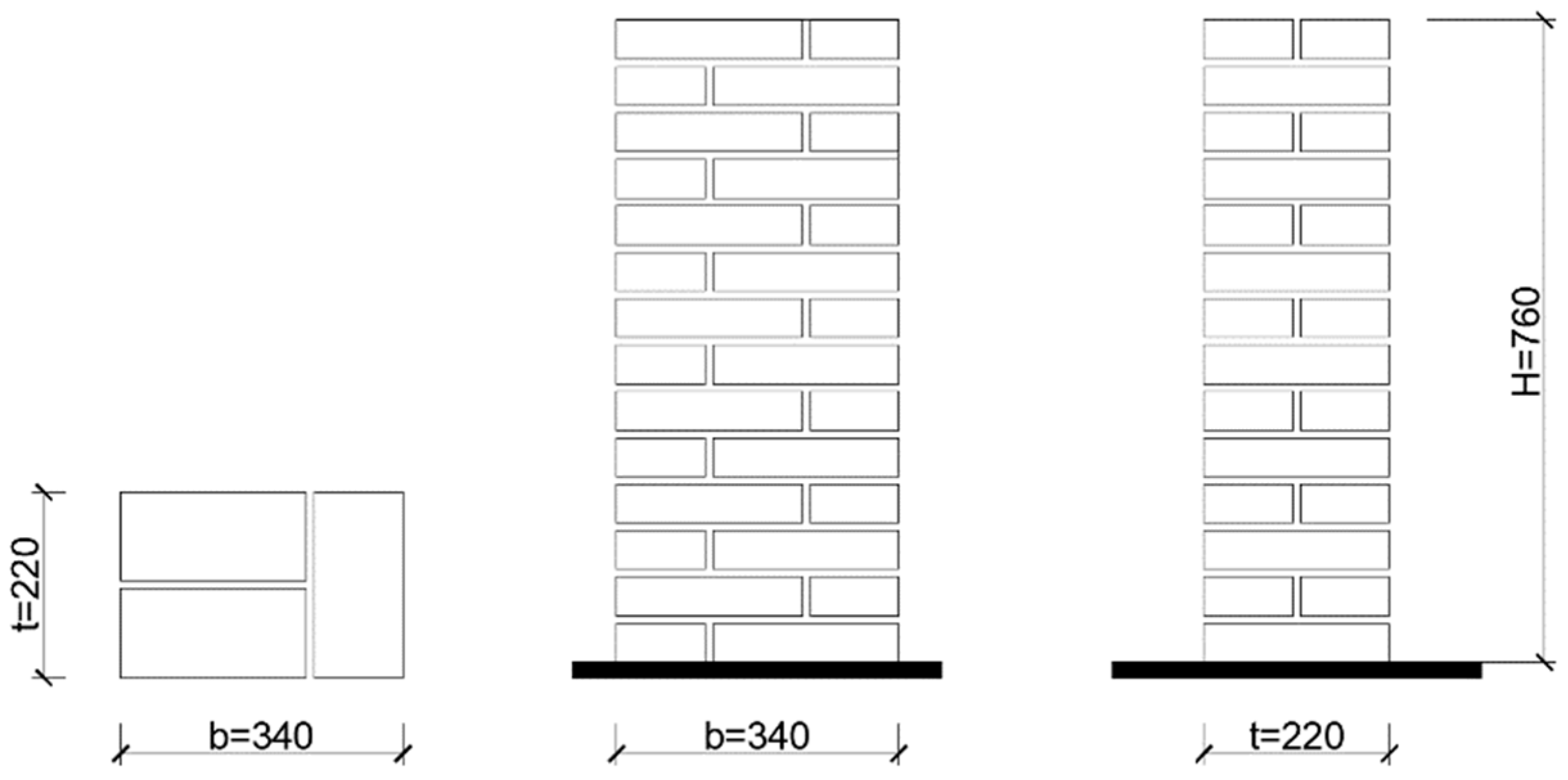
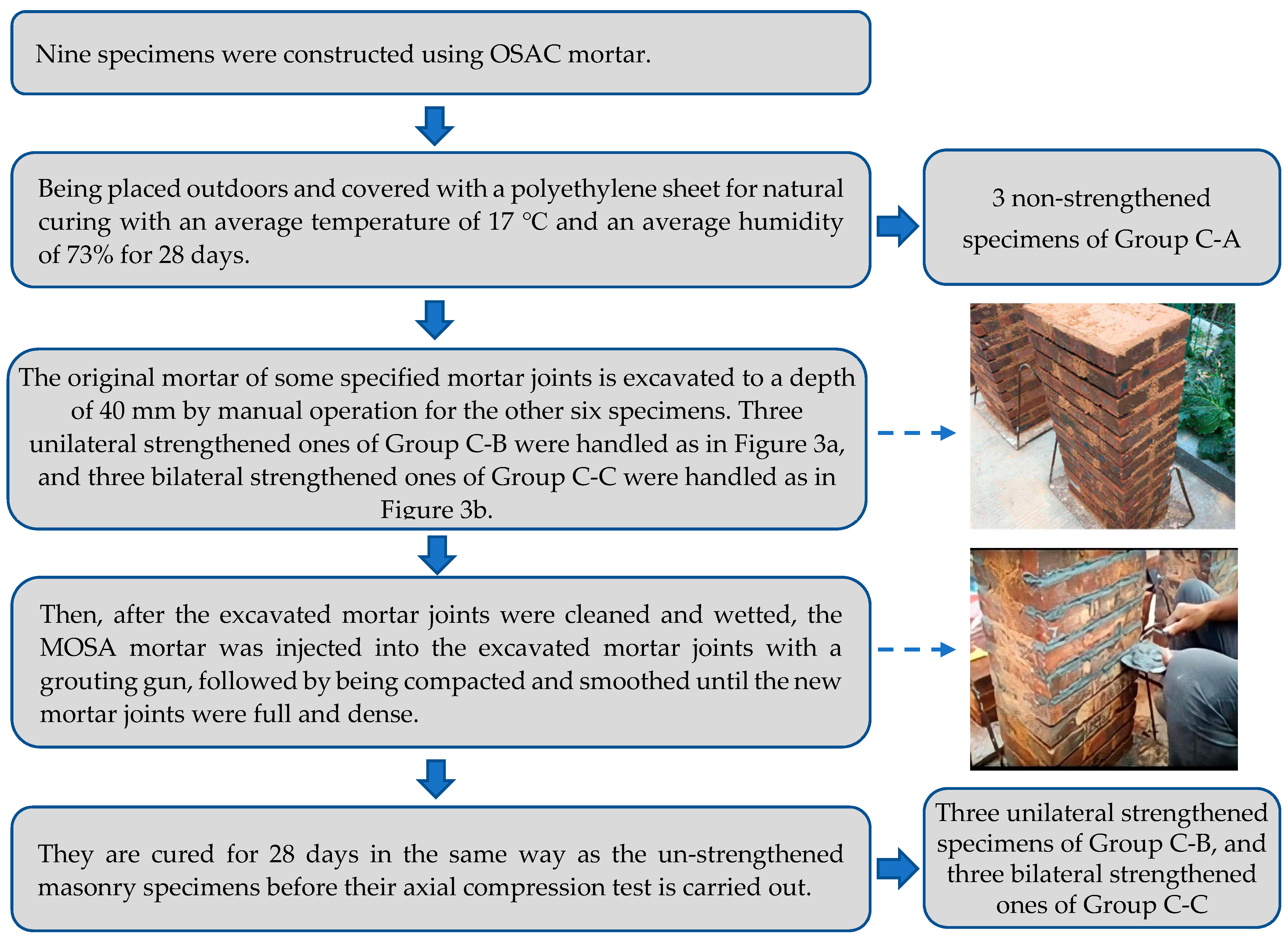
2.1. Materials and Specimens

In line with the industry standard [16] on masonry experiments, the specimens in this study were constructed with 14 rows of bricks. Each row contained 3 fired clay bricks with average sizes of 225 mm × 105 mm × 45 mm, as shown in Figure 1. The thickness of mortar joints was limited to 10 mm, implying that the total dimensions of the resultant specimens were 340 mm × 220 mm × 760 mm (b × t × H). The fired clay bricks were supplied by a local manufacturer of prefabricated building products. Two kinds of mortars were used during the construction of specimens: the oyster shell ash-clay mortar (OSAC mortar) with low strength (i.e., the main type of mortar used in historical masonry in China’s coastland [17]) and the MOSA mortar developed by Wu Qixin [18], which shows higher strength and better working performance than the OSAC mortar. The OSAC mortar was used to construct masonry specimens that needed to be strengthened, whereas the MOSA mortar was used as a replacement mortar to strengthen the specimens. The mix design of the OSAC mortar and MOSA mortar was the same as those used in previous research [5]. The specific mix design is given in Table 1. As the preparation method of MOSA mortar is still in the process of patent application, the detailed names of the two kinds of additive materials are not given. Instead, they are represented by the letters A and B. The compressive strength of the three materials is given in Table 2. The detailed construction method of the specimens is shown in Figure 2.

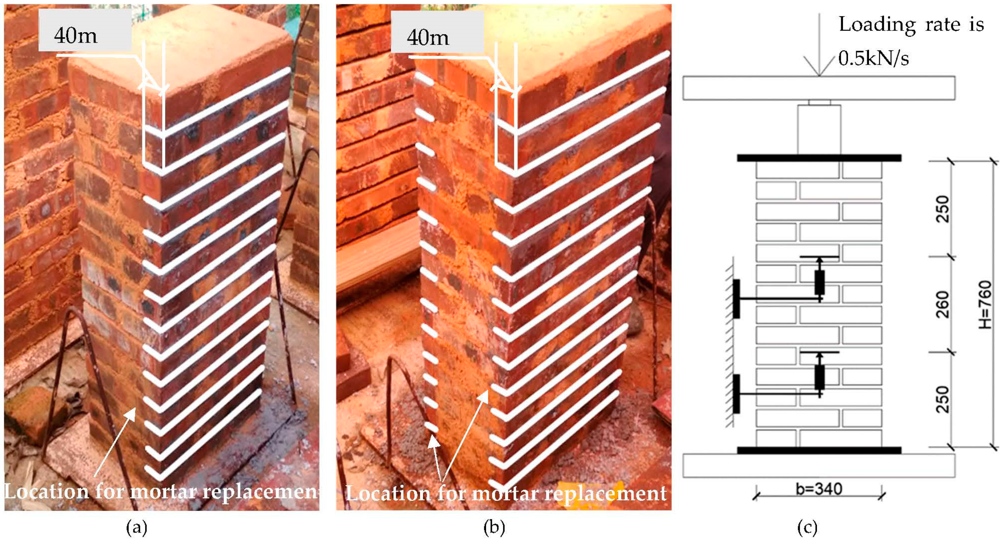
2.2. Axial Compressive Test

The compressive experiments were conducted in line with the industry standard [16] for masonry experiments. As seen in Figure 3c, the specimens were tested with a hydraulic pressure tester that had a capacity equal to 8000 kN. The applied compression load was measured by placing the load cell between the upper platen of the testing machine and the specimen, with a thick steel plate being placed on the top of the specimen to prevent possible local failure. Moreover, four electrical resistance displacement sensors were arranged on the trisection points of the symmetry lines on the front and rear sides of the specimen. The difference measured by the two displacement sensors on the same side represents the axial deformation along the middle part of the specimen. Then, the axial strain was obtained by dividing the average deformation of both sides by the initial axial length of the middle part of the specimen. The axial compressive stress was obtained by dividing the applied load by the specimen’s initial cross-sectional area. The surfaces of the specimens were coated with a thin layer of white paint to facilitate the observation of cracks. Tests were performed in the load control mode with a uniform speed of 0.5 kN/s.

3. Test Results and Discussion

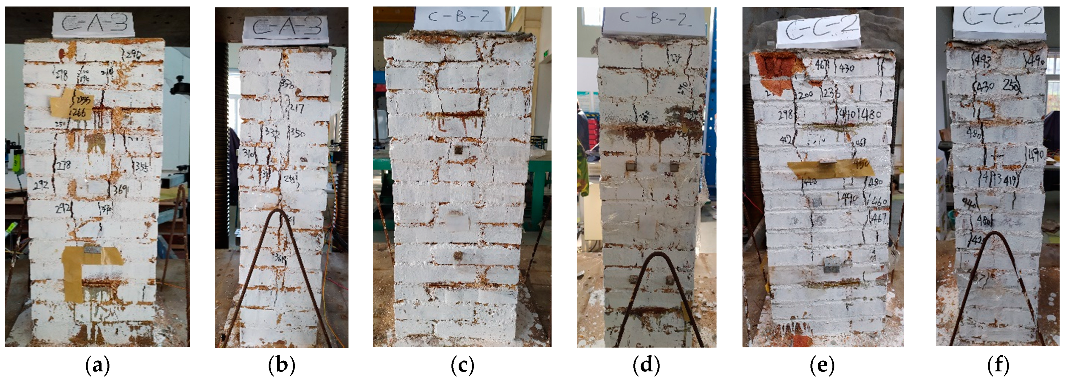
3.1. Failure Characteristics of Specimens

The failure process for strengthened specimens and non-strengthened specimens under axial compression was similar. Figure 4 shows the failure modes for the three kinds of specimens. It was observed that the first crack occurred on the long side of the specimen along the vertical mortar joint at about 40–60% of the ultimate failure load. As the load increased, more vertical cracks spread both on the long and short sides of the specimen. In the meantime, tiny cracks occurred in the initial phase and gradually increased their length and width. When the load reached 80–90% of the ultimate failure load, several localized vertical cracks connected to form penetrating cracks along the height across several layers of bricks. These kinds of penetrating cracks could be found both on the long and short sides of the specimen. The specimen was then disintegrated at the ultimate load, accompanied by the spalling of the brick face shells.
The main difference between the strengthened specimens and un-strengthened specimens is the location of the cracks. As shown in Figure 4, cracks used to occur on the vertical mortar joints in the long and short sides for all specimens. However, for strengthened specimens, vertical cracks also occurred on the junction between the original mortar and the newly-replaced mortar, as shown in Figure 4d,f. For the strengthened specimens, the new mortar and original mortar produced equal compressive strains as a result of compatibility during loading. However, due to the different elastic modulus of the two mortars, their reaction forces on bricks were different. Consequently, the shear stress of bricks on the junction between the new and old mortars increased, which could have caused the bricks to crack at this location.

3.2. Compressive Strength

The compressive experiment results are listed in Table 3. N u is the peak value of compressive loading, f c , i is the compressive strength, f c , m is the average compressive strength of the three specimens in one group, and C o V f c is the variation coefficient. In line with the industry standard [16] on masonry experiments, the tested compressive strength f c , i can be given as follows:
f c , i = N u A
where A is the cross-sectional area of the specimen.
As seen in Table 3, the average compressive strength f c , m for non-strengthened specimens in Group C-A was 5.17 MPa. According to the industry standard [19] on masonry designs, 5.26 MPa is the recommended compressive strength value for masonry made of fired clay brick with a compressive strength of 25 MPa and cement mortar with a compressive strength of 5 MPa. Here, the specimens in Group C-A were made of fired clay brick with a compressive strength of 24.37 MPa and OSAC mortar with a compressive strength of 0.53 MPa. The comparison indicates that the OSAC mortar with a compressive strength of 0.53 MPa played a similar role in masonry to the cement mortar with a compressive strength of 5 MPa. The reason may be that the mix workability of OSAC mortar was better than that of the cement mortar, thus better eliminating the uneven stress on bricks. It has also been reported that the strength of masonry built via lime mortar with low strength is higher than expected [20,21,22]. This explains why most existing historical lime mortar masonry buildings are well preserved if no earthquakes have occurred. Thus, the compressive strength of historical masonry buildings made of fired clay brick and OSAC mortar can essentially meet the requirements of vertical load bearing. The main purpose for strengthening these buildings is to improve their shear strength in resisting earthquake action.
As seen in Table 3, the average compressive strength f c , m for unilateral strengthened specimens in Group C-B was 5.83 MPa. For bilateral strengthened specimens in Group C-C, it was 5.93 MPa, showing increases of 11.3% and 11.5%, respectively, compared with that for non-strengthened specimens in Group C-A. A previous study showed that the compressive strength of brick masonry specimens strengthened by replacement with high-strength cement mortar decreased due to the stress concentration on bricks caused by high-strength cement mortar in mortar joints [23]. On the contrary, our test results showed that being strengthened by replacements with high-strength MOSA mortar played a positive role in the compressive performance of the strengthened specimens. The reason for this was that the MOSA mortar had good compatibility with the original OSAC mortar. These test results show that the compressive strength of specimens strengthened with MOSA mortar can be maintained or even improved, while the strengthening purpose of significantly improving their shear strength were confirmed by a previous study [5].

3.3. Calculation of Compressive Strength

As for the compressive strength of masonry made of fired clay brick and OSAC mortar f c o , as well as strengthened masonry f c s , there is no suitable formula for calculating either of them yet. With regard to the compressive strength for masonry made of fired clay brick and cement mortar f c c , the industry standard [19] on masonry design provides the following formula:
f c c = 0.78 f 1 0.5 ( 1 + 0.07 f 2 ) k
where f 1 and f 2 are the compressive strength of fired clay brick and cement mortar, respectively. k is the correction coefficient that accounts for mortar strength, and when f 2 < 1 , k = 0.6 + 0.4 f 2 . Otherwise, it is k = 1 .
Taking into consideration the different mortars used, calculating compressive strength for masonry made of fired clay brick, OSAC mortar f c o , and strengthened masonry f c s can be obtained by modifying Equation (2):
f c o = 0.78 f 1 0.5 ( 1 + 0.07 f 2 ) k φ 1
f c s = 0.78 f 1 0.5 ( 1 + 0.07 f 2 ) k φ 1 φ 2
where φ 1 and φ 2 are modifying coefficients. As mentioned in Section 3.2, OSAC mortar was found to have a better performance than cement mortar in eliminating uneven stress on bricks, which could improve the compressive strength of the masonry. Here, φ 1 is used to account for this kind of improvement effect. In Equation (3), f 1 , f 2 , and k are known parameters. Then, by substituting the different tested compressive strength f c , i for the specimens in Group C-A for f c o , coefficient φ 1 can be obtained. The calculated φ 1 is 1.59 on average, and the variation coefficient is 0.054. For the specimens strengthened by replacing the original mortar with the MOSA mortar, the MOSA mortar has both positive and negative effects on their compressive strength. On the one hand, the replacement of higher strength MOSA mortars can cause stress concentration on the bricks, which can reduce the compressive strength of the strengthened specimens. Moreover, φ 2 is used to account for this reduction effect. On the other hand, the replacement of higher strength MOSA mortars can reduce the transverse deformation of mortar joints, which thus can decrease the tensile stress that acts on bricks. Therefore, compressive strength of the strengthened specimens can improve. This enhancement is accounted for by the increase of f 2 in Equation (4), which is calculated as such:
f 2 = f 2 o t 1 t + f 2 s t 2 t
where f 2 o and f 2 s are the compressive strength of the original OSAC mortar and that of the MOSA mortar, respectively. t 1 and t 2 are the thickness of the original OSAC mortar joints untouched and the replaced MOSA mortar joints, respectively. t is the thickness of the specimens, wherein t = t 1 + t 2 .
In Equation (4), f 1 , f 2 , k , and φ 1 are known parameters. By substituting the different tested compressive strength f c , i for various specimens in Group C-B and Group C-C for f c s , the coefficient φ 2 can be obtained. The calculated φ 2 is 0.90 on average, and the variation coefficient is 0.111.
Thus, the compressive strength of tested specimens can be calculated via Equations (3)–(5). As seen in Table 3, the calculated compressive strength f c , i c is consistent with the tested value f c , i .

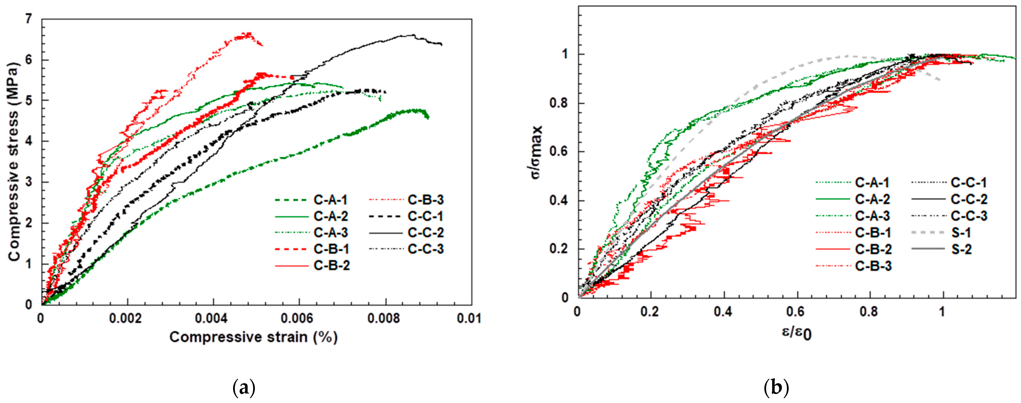
3.4. Stress–Strain Relationship

Besides compressive strength, the stress–strain relationship is another important property to understand and describe the behavior of masonry under compression. The stress–strain (σ-ε) curves illustrated in Figure 5a were drawn from the test data, as described in Section 2.2. Green curves are experimental results for un-strengthened specimens in Group C-A. Red ones are experimental results for unilateral strengthened specimens in Group C-B. Moreover, black ones are experimental results for bilateral strengthened specimens in Group C-C. According to Figure 5a, it was difficult to find out if there was any rule change in the stress–strain curves between different groups of specimens. For this reason, the curves in Figure 5a were normalized by their maximum stress point (the maximum compressive strength σmax and corresponding strain ε0), and thus Figure 5b was obtained. As shown in Figure 5b, the curves for specimens C-A-2 and C-A-3 in Group C-A had an obvious turning point at around 70% of the ultimate load. Their deformation increased significantly at the later stage of loading. This may be due to their low strength mortar, which could lead to the early loss of their strength and soon be out of work prior to the failure of the specimens. As for specimen C-A-1 in Group C-A, there was no obvious turning point in its curve at Figure 5b. However, it can be seen from Figure 5a that its deformation in the initial loading phase was already large, indicating that the strength of the mortar in this specimen may be even lower than that in the other two specimens in Group C-A. As for specimens in Group C-B and Group C-C, the deformation growth was smooth during the whole loading process, as shown in Figure 5b, and there was no obvious turning point in their curves. The reason may be that when the original mortar was partially replaced with a high strength, modified mortar, the new mortar would have a strain lag in the initial loading stage, then gradually participate in work and make up for the gradual loss of strength in the original mortar until the masonry reaches failure.
Powell and Hodgkinson [24] proposed a parabolic model to describe the stress–strain relationship for masonry under axial compression:
σ σ m a x = A ( ε ε 0 ) + B ( ε ε 0 ) 2 ( 0 ε ε 0 1.0 )
where A and B are coefficients that can be obtained from experimental data. This model can be used to simulate the test results in this paper. The value of coefficients A and B for non-strengthened specimens were obtained from experimental data of specimens C-A-2 and C-A-3. For strengthened specimens, samples were obtained from experimental data in Groups C-B and C-C (Table 4). R 2 is the correlation coefficient for the simulation results of Equation (6). As shown in Table 4, the value of R 2 in the simulation results for non-strengthened specimens was 0.93. It was 0.96 for strengthened specimens. The simulation stress–strain curves S-1 for non-strengthened specimens and S-2 for strengthened specimens are also shown in Figure 5b, which indicates that the simulation curve S-2 is in agreement with the experimental data; however, there was some deviation for S-1.

4. Conclusions

This paper presented a compressive strength test to investigate the compressive behaviors of brick masonry strengthened with MOSA mortar. Nine specimens, including three non-strengthened ones, three unilateral strengthened ones, and three bilateral strengthened ones, were fabricated and tested. Low strength OSAC mortar was used to construct masonry specimens that needed to be strengthened, whereas the high strength MOSA mortar was used as a replacement mortar to strengthen the specimens. The compressive performance, including failure characteristics, tested compressive strength, and stress–strain relationship, of the three kinds of specimens were compared. The calculation method of their compressive strength was also discussed. The major findings from this study are as follows:
  • The failure process of strengthened and non-strengthened specimens under axial compression was similar. They all experienced initial cracking and crack propagation and were disintegrated at ultimate load. The major difference was the location of cracks. For strengthened specimens, vertical cracks occurred on the junction between the original mortar and the replaced mortar, besides on the vertical mortar joints as those of non-strengthened specimens.
  • The compressive strength of non-strengthened specimens made of fired clay brick and OSAC mortar met the requirements of vertical load bearing. The main purpose of strengthening these kinds of masonry buildings was to improve their shear strength in resisting earthquake action. Compared with the non-strengthened specimens, the compressive strength for unilateral strengthened specimens increased by 11.3% on average. Moreover, for bilateral strengthened specimens, the value increased by 11.5% on average. The experimental results showed that the compressive strength of specimens strengthened with MOSA mortar also improved, although the main strengthening purpose was to improve their shear strength.
  • The formulas to calculate compressive strength for brick masonry made with OSAC mortar and those strengthened with MOSA mortar were obtained by fitting the test results. The calculated values were consistent with the tested ones.
  • The stress–strain relationship of tested specimens under axial compression were simulated using a parabolic model. The simulation results for strengthened specimens were consistent with the experimental data.
However, for the brick masonry specimens strengthened with MOSA mortar, only experimental research into their basic mechanical properties, such as shear and compression behavior, have been carried out to date. This is far from enough for the application of this strengthening method in practice. Therefore, further experimental investigations will be needed to confirm their validity. In our next project, a low-cycle test on brick masonry walls strengthened with MOSA mortar is expected to be carried out to investigate their seismic performance.

Author Contributions

Conceptualization, Z.C., J.S., Y.X., and H.H.; methodology, Z.C., J.S., Y.X., and H.H.; validation, Z.C.; formal analysis, Z.C., W.C., and C.M.; investigation, Z.C., W.C., and C.M.; resources, J.S.; data curation, W.C. and C.M.; writing—original draft, Z.C., W.C., and C.M.; writing—review and editing, Z.C., J.S., and Y.X.; supervision, J.S.; project administration, J.S.; funding acquisition, J.S. and Y.X. All authors have read and agreed to the published version of the manuscript.

Funding

This research was found by the Administrative Committee of Xiamen Gulangyu-Wanshishan Scenic Area. The APC was funded by Xiamen University.

Institutional Review Board Statement

Not applicable.

Informed Consent Statement

Not applicable.

Data Availability Statement

The data presented in this study are available on request from the corresponding author.

Conflicts of Interest

The authors declare no conflict of interest.

References

  1. Survey Report Collection of Historical Buildings in Gulangyu; Xiamen Engineering Testing Center Co., Ltd.: Xiamen, China, (unpublished).
  2. Xie, Q.; Xue, J.; Zhao, H. Seismic damage investigation and analysis of ancient buildings in Wenchuan earthquake. J. Build. Struct. 2010, 31, 18–23. [Google Scholar]
  3. Pan, Y.; Tang, L.; Wang, H.; Yao, Y. Investigation and analysis of damage to ancient buildings in Lushan Ms 7.0 earthquake. Earthq. Eng. Eng. Dyn. 2014, 34, 140–146. [Google Scholar]
  4. Ministry of Housing and Urban-Rural Development of the People’s Republic of China. GB/T 39056-2020, Technical Code for Maintenance and Strengthening of Masonry Structures on Ancient Buildings; Standards Press of China: Beijing, China, 2020; p. 3.
  5. Chen, Z.; Tang, Y.; Mai, C.; Shi, J.; Xie, Y.; Hu, H. Experimental study on the shear performance of brick masonry strengthened with MOSA mortar. Case Stud. Constr. Mater. 2020, 13, e00469. [Google Scholar]
  6. Almeida, C.; Guedes, J.P.; Arede, A.; Costa, C.Q.; Costa, A. Physical characterization and compression tests of one leaf stone masonry walls. Constr. Build. Mater. 2012, 30, 188–197. [Google Scholar] [CrossRef]
  7. Luso, E.; Lourenço, P.B. Experimental characterization of commercial lime-based grouts for stone masonry consolidation. Constr. Build. Mater. 2016, 102, 216–225. [Google Scholar] [CrossRef] [Green Version]
  8. Funari, M.F.; Verre, S. The effectiveness of the DIC as a measurement system in SRG shear strengthened reinforced concrete beams. Crystals 2021, 11, 265. [Google Scholar] [CrossRef]
  9. Ombres, L.; Verre, S. Analysis of the behavior of FRCM confined clay brick masonry columns. Fibers 2020, 8, 11. [Google Scholar] [CrossRef] [Green Version]
  10. Gianmarco, D.F.; Stefano, D.S. State of the art of steel reinforced grout applications to strengthen masonry structures. Am. Concr. Inst. ACI Spec. Publ. 2018, SP326, 142064. [Google Scholar]
  11. Silva, B.; Pigouni, A.E.; Valluzzi, M.R.; Modena, C. Calibration of analytical formulations predicting compressive strength in consolidated three-leaf masonry walls. Constr. Build. Mater. 2014, 64, 28–38. [Google Scholar] [CrossRef]
  12. Lucchini, S.S.; Facconi, L.; Minelli, F.; Plizzari, G. Retrofitting unreinforced masonry by steel fiber reinforced mortar coating: Uniaxial and diagonal compression tests. Mater. Struct. 2020, 53, 144. [Google Scholar] [CrossRef]
  13. Furtado, A.; Rodrigues, H.; António, A.; José, M.; Humberto, V. The use of textile-reinforced mortar as a strengthening technique for the infill walls out-of-plane behaviour. Compos. Struct. 2021, 255, 113029. [Google Scholar] [CrossRef]
  14. Meghwal, P.; Singhal, V.; Tripathy, D. Strengthening of lime mortar masonry wallettes using fiber-reinforced cementitious matrix. J. Compos. Constr. 2020, 24, 04020075. [Google Scholar]
  15. Parisi, F.; Iovinella, I.; Balsamo, A.; Augenti, N.; Prota, A. In-plane behaviour of tuff masonry strengthened with inorganic matrix–grid composites. Compos. Part B Eng. 2013, 45, 1657–1666. [Google Scholar] [CrossRef]
  16. Ministry of Housing and Urban-Rural Development of the People’s Republic of China. GB/T 50129-2011, Standard for Test Methods of Basic Mechanical Properties of Masonry; China Architecture and Building Press: Beijing, China, 2011; pp. 7–10.
  17. Song, Y. Exploitation of the Works of Nature (Tiangong Kaiwu); Harbin Press: Harbin, China, 2009; pp. 251–252. [Google Scholar]
  18. Wu, Q. The Research of Modification on the Replacement of Mortar to Reinforce the Gulangyu Historical Buildings. Master’s Dissertation, Xiamen University, Xiamen, China, 2020. [Google Scholar]
  19. Ministry of Housing and Urban-Rural Development of the People’s Republic of China. GB 50003-2011, Code for Design of Masonry Structures; China Architecture and Building Press: Beijing, China, 2011; pp. 112–115.
  20. Segura, J.; Pelà, L.; Roca, P. Monotonic and cyclic testing of clay brick and lime mortar masonry in compression. Constr. Build. Mater. 2018, 193, 453–466. [Google Scholar] [CrossRef]
  21. Bompa, D.V.; Elghazouli, A.Y. Compressive behaviour of fired-clay brick and lime mortar masonry components in dry and wet conditions. Mater. Struct. 2020, 53, 1–21. [Google Scholar] [CrossRef]
  22. Drougkas, A.; Roca, P.; Molins, C. Compressive strength and elasticity of pure lime mortar masonry. Mater. Struct. 2015, 49, 983–999. [Google Scholar] [CrossRef] [Green Version]
  23. Wang, X. Experimental Study on Mechanics of Historic Masonry Walls Strengthened with Mortar Replacement. Master’s Dissertation, Xiamen University, Xiamen, China, 2019. [Google Scholar]
  24. Shi, C. Theory and Design of Masonry Structure, 3rd ed.; China Architecture and Building Press: Beijing, China, 2014; pp. 63–64. [Google Scholar]
Figure 1. Geometry of the tested specimens.
Buildings 11 00266 g001
Figure 2. The construction method of the specimens.
Buildings 11 00266 g002
Figure 3. Specimens and their loading method. (a) Unilateral strengthened specimens (C-B); (b) bilateral strengthened specimens (C-C); (c) the loading method.
Buildings 11 00266 g003
Figure 4. Ultimate crack patterns: (a) Long side of C-A-3; (b) short side of C-A-3; (c) long side of C-B-2; (d) short side of C-B-2; (e) long side of C-C-2; (f) short side of C-C-2.
Buildings 11 00266 g004
Figure 5. Compressive stress–strain curves. (a) Un-normalized curves; (b) normalized curves.
Buildings 11 00266 g005
Table 1. Compositions of mortars.
Mortar TypeMix Proportions by Mass
OSAC mortaroyster shell ash/sand/clay/water
1:0.5:3:0.15
MOSA mortaroyster shell ash/siliceous material A/aluminous material B/sand/water
0.8:0.15:0.05:3:0.2
Table 2. The compressive strength of materials.
MaterialOSAC MortarMOSA MortarBrick
Compressive Strength/MPa0.535.6924.37
Table 3. Results of the compressive test.
Specimen Code N u / kN f c , i / MPa f c , m / MPa C o V f c f c , i c / kN f c , i c / f c , i
C-A-1362.8 4.85 5.170.0445.161.06
C-A-2401.1 5.36 0.96
C-A-3396.3 5.30 0.97
C-B-1421.3 5.63 5.830.0835.711.02
C-B-2486.2 6.50 0.88
C-B-3401.0 5.36 1.07
C-C-1417.9 5.59 5.930.1146.081.09
C-C-2514.4 6.88 0.89
C-C-3398.5 5.33 1.14
Table 4. Simulation parameters of the stress–strain relationship.
Specimen TypeAB R 2
Non-strengthened specimen2.63−1.740.93
Strengthened specimen1.61−0.620.96
Publisher’s Note: MDPI stays neutral with regard to jurisdictional claims in published maps and institutional affiliations.

