
Masonry Dome Behavior under Gravity Loads Based on the Support Condition by Considering Variable Curves and Thicknesses


Abstract
:1. Introduction
2. Evolution of Masonry Dome Analysis
2.1. Primitive Analysis of Masonry Dome without Considering the Neutral Hoop
2.2. Single Neutral Hoop (Double-Masonry Dome Behavior) Roles in Masonry Dome Analysis
2.3. An Important Step for Masonry Dome Analysis
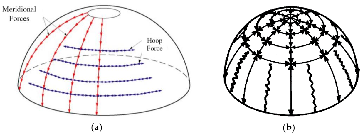
- Applied loads are resisted by internal forces within the surface, which have no stiffness against bending; therefore, internal forces are either pure tension or pure compression;
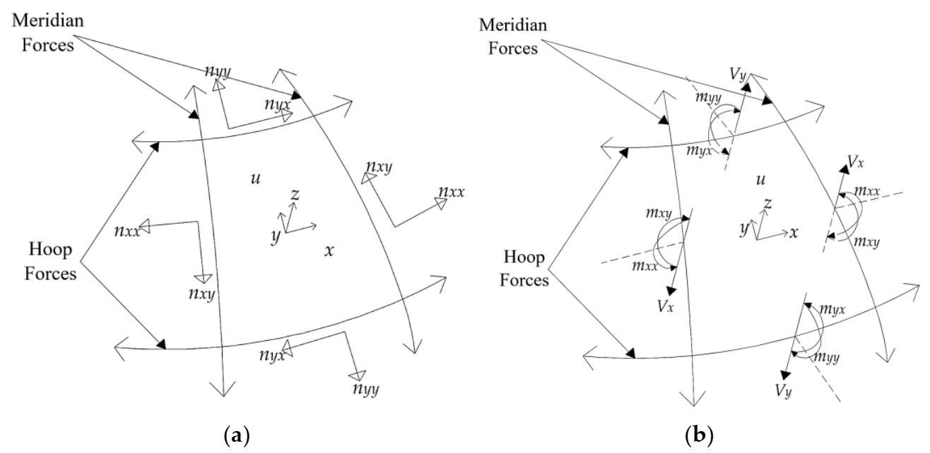
- On asymmetrically and uniformly loaded domes, internal forces act perpendicularly to each other in the meridional and latitudinal, or hoop, directions;
- Internal forces are coplanar; that is, the membrane has zero thickness;
- The membrane plane is located along the centerline of the dome’s adequate thickness; thus, the thrust lines must also lie on this median surface.
2.4. Numerical Analysis of Masonry Domes without Considering the Neutral Hoop
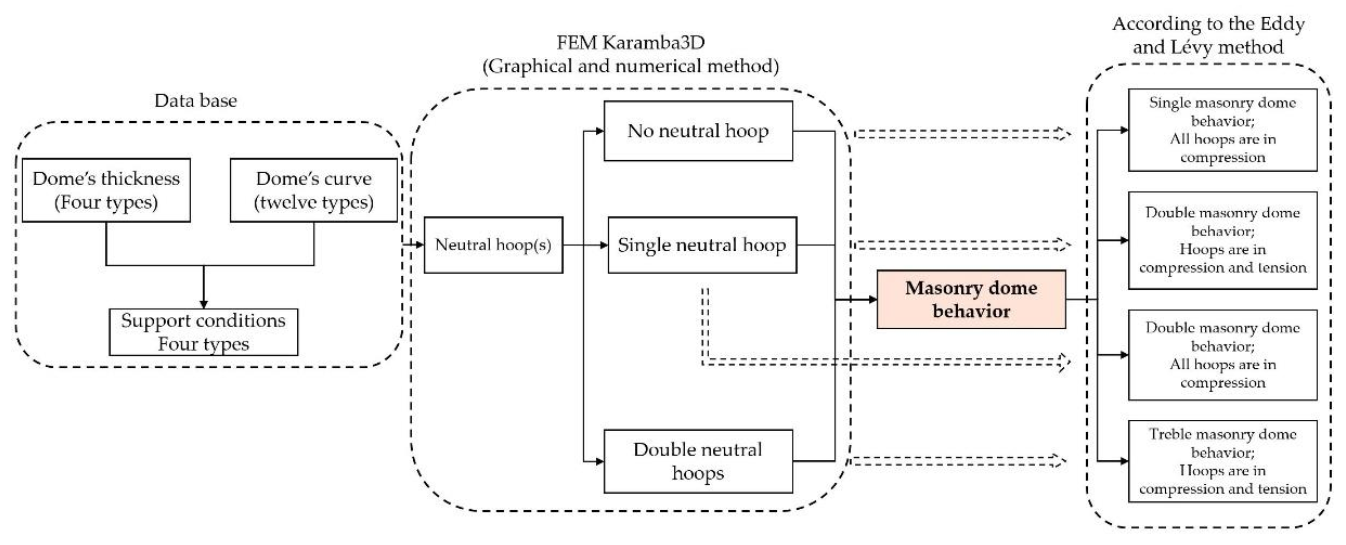
3. Method
4. New Perspective of Masonry Dome Behavior
4.1. Initial Information of Masonry Dome Analysis
4.2. Case Studies
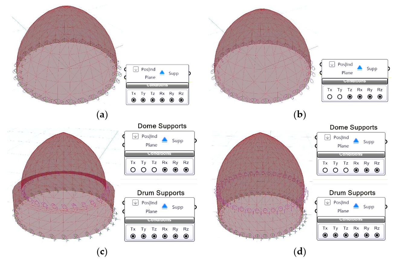
4.2.1. Fixed Support
- In the dome, its curve is part of the circle—133° out of 360°—all hoops are in compression, and there is no neutral hoop;
- In the dome, its curve is part of the circle—167° out of 360°—all hoops are in compression, and there is a single neutral hoop;
- Except for the previous case studies, in other domes, there are double neutral hoops. Hoops are in tension in the blue color zone, and hoops are compressed in the red color zone;
- As the height-to-span ratio decreases (the horizontal vector of the thrust line increases), the tension zone decreases, finally reaching zero.
- In the dome, its curve is part of the circle—133° out of 360°—and increasing the thickness does not affect the number of neutral hoops. All hoops are in compression, and there is no neutral hoop;
- In the dome, its curve is part of the circle—167° out of 360°; there are double neutral hoops (hoops are in compression and tension) by decreasing the dome’s thickness from a thickness of 90 cm. There is a single neutral hoop in thickness of 90 cm, and hoops are in compression. There is no neutral hoop in the thickness of more than 90 cm, and all hoops are in compression;
- In the dome, its curve is part of the circle—227° out of 360°; there are always double neutral hoops. Changing the dome’s thickness does not affect the number of neutral hoops;
- In domes other than those mentioned above, there is a single neutral hoop in a specific thickness; for less than this thickness, there are double neutral hoops, and for more than this thickness, there is no neutral hoop.
4.2.2. Free Support in X- and Y-Axes
- In the dome, its curve is part of the circle—227° out of 360°; there is a double neutral hoop. In the others, there is a single neutral hoop;
- As the height-to-span ratio decreases (the horizontal vector of the thrust line increases), the tension zone decreases.
- In the dome, its curve is part of the circle—227° out of 360°—double neutral hoops for dome’s thickness are less than 138 cm, and for more than 138 cm, there is a single neutral hoop. In the others, there is a single neutral hoop;
- Increasing the dome’s thickness makes the tension area larger.
4.2.3. Free Support in All Axes (Domes Placed on a Drum)
- In all curves except the part of the circle—227° out of 360°—there is a single neutral hoop;
- In the dome, its curve is part of the circle—227° out of 360°; there are double neutral hoops;
- As the height-to-span ratio decreases (the horizontal vector of the thrust line increases), the compressive zone increases.
4.2.4. Free Support in All Axes (Domes Placed on a Drum and a Pendentive)
- In the dome, its curve is part of the circle—133° out of 360°; for thicknesses less than 185 cm, there is a single neutral hoop, and there are double neutral hoops for thicknesses more than 185 cm;
- In the dome, its curve is part of the circle—167° out of 360°. For thicknesses less than and equal to 52 cm, there are double neutral hoops; for thicknesses more than 52 and less than 166 cm, there is a single neutral hoop; and for thicknesses more than 166, there is no neutral hoop;
- In the dome, its curve is part of the circle—227° out of 360°; there are double neutral hoops for all thicknesses;
- In the dome with the raised Panj o haft curve, there is a single neutral hoop for thicknesses less than 195 and double neutral hoops for thicknesses more than 195 cm;
- In the dome with the raised Shakhbozi curve, there are double neutral hoops for thicknesses less than and equal to 45 cm; a single neutral hoop for thicknesses more than 49 cm and less than 192 cm; and double neutral hoops for thicknesses more than and equal to 192 cm;
- In domes other than those mentioned above, there are double neutral hoops for less than a specific thickness, a single neutral hoop for the specific thickness, and no neutral hoop for more than the specific thickness.
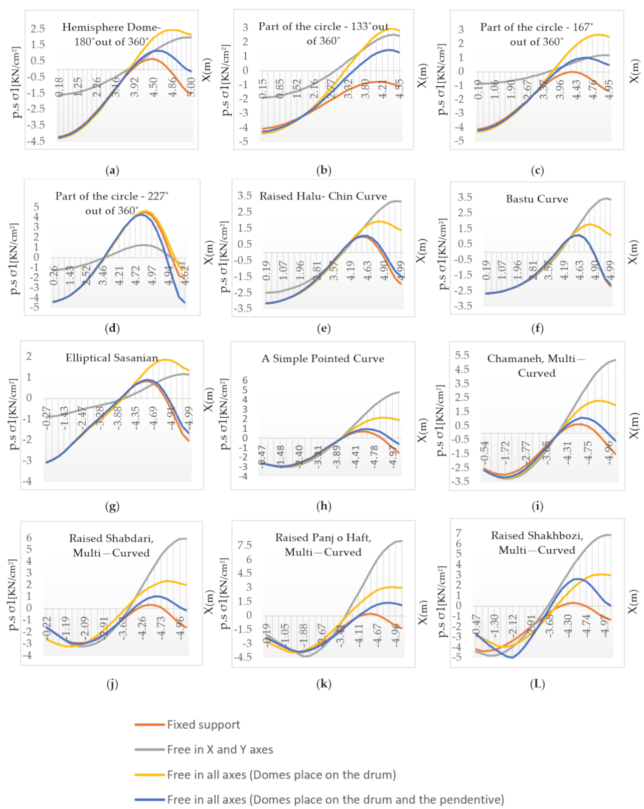
4.3. Diagram of Masonry Domes (p.s σ1) Separately Based on a Curve with Constant 90 cm Thickness and Variable Support
- a. In a hemispherical dome—180°of 360°—the upper neutral hoop is in an almost specific place. The dome’s behavior is most different in the lower part, and it is different in the neutral hoop number and tensile stress. The compression stress is almost equal in all supports except the free X and Y support;
- b. The behavior in the part of the circle—133°out of 360°—is different from that in the other parts. In fixed support conditions, there is no neutral hoop. However, in other supports, there is one. The p.s σ1 is different in different support conditions;
- c. The behavior of the domes shown in Figure 5a,c is similar, except in the fixed support. There is a single neutral hoop in the fixed support with all the compressive hoops;
- d. In the curve with the part of the circle—227°of 360°—before the maximum tensile stress, all types of supports are very similar, except the free support in X and Y. The lowest maximum tension and compression stress are in the dome with the free support in X and Y;
- e. In the dome with the raised Halu–Chin curve, domes with a fixed support and free in all axes (domes placed on a drum and a pendentive) have similar behavior with double neutral hoops. Additionally, the maximum tensile stress is in the free X and Y support;
- f. In the dome with the Bastu curve, its behavior at the top of the upper neutral hoop is similar in all types of support conditions, and the upper neutral hoop is located in almost the same place. The dome’s diagrams with fixed support and free in all axes (domes placed on a drum and a pendentive) are the same;
- g. In the dome with an elliptical Sasanian curve, the upper neutral hoop in all types of support is in an almost specific place. The same behavior is observed for the fixed support and free in all axes (domes placed on a drum and a pendentive) support;
- h and i. The masonry dome behavior in the two figures is similar. The compression region is almost the same in all types of support. There are double neutral hoops in fixed support and free in all axes (domes placed on a drum and a pendentive), and there is a single neutral hoop in the other types of support;
- k. In the dome with a raised Panj o haft curve, there is a single neutral hoop in all conditions except the fixed support conditions;
- l. The behavior of the dome with the raised Shakhbozi Curve is similar to that observed in Figure 5k, though there is some difference in the compression and tension region.
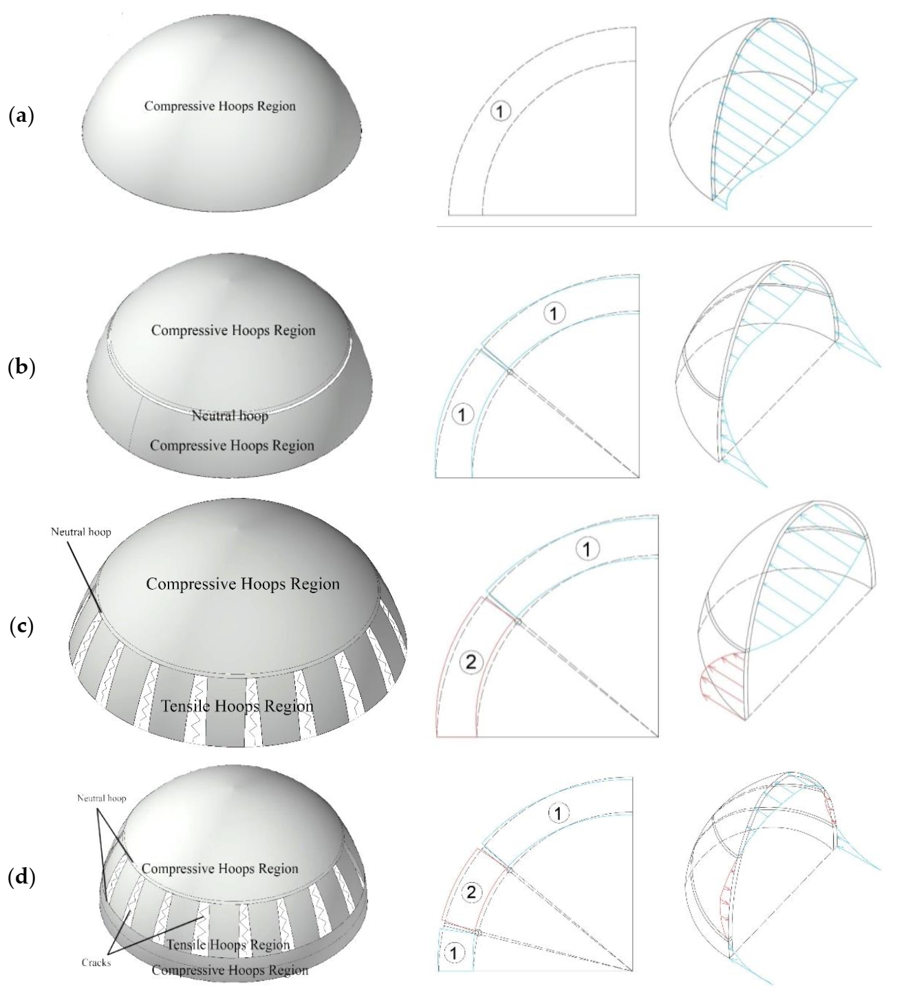
4.4. Masonry Dome Behavior
- No neutral hoop, single masonry behavior;
- Single neutral hoop—all hoops are compressive, double-masonry behavior;
- Single neutral hoop—hoops are compressive and tensile, double-masonry behavior;
- Double neutral hoops, treble-masonry dome.
5. Conclusions
- Single-masonry behavior;
- Double-masonry behavior, where all hoops are compressive;
- Double-masonry behavior, where hoops are compressive and tensile;
- Treble-masonry dome.
Author Contributions
Funding
Institutional Review Board Statement
Informed Consent Statement
Data Availability Statement
Acknowledgments
Conflicts of Interest
References
- Melaragno, M. An Introduction to Shell Structures: The Art and Science of Vaulting; Van Nostrand Reinhold: New York, NY, USA, 1991; p. 4. [Google Scholar]
- Lagomarsino, S.; Podestà, S. Seismic Vulnerability of Ancient Churches: I. Damage Assessment and Emergency Planning. Earthquake Spectra 2004, 20, 377–394. [Google Scholar] [CrossRef]
- Fuentes, D.D.; Baquedano Julià, P.A.; D’Amato, M.; Laterza, M. Preliminary seismic damage assessment of Mexican churches after September 2017 earthquakes. Int. J. Archi. Herit. 2019, 1–21. [Google Scholar] [CrossRef]
- Galassi, S.; Misseri, G.; Rovero, L.; Tempesta, G. Equilibrium analysis of masonry domes, on the analytical interpretation of the Eddy-Lévy graphical method. Int. J. Archit. Herit. 2017, 11, 1–34. [Google Scholar] [CrossRef]
- Heyman, J. The Stone Skeleton; Cambridge University Press: Cambridge, UK, 1995. [Google Scholar]
- Como, M. Statics of Historic Masonry Constructions; Springer: Berlin, Germany, 2017; pp. 195–297. [Google Scholar]
- Eliassen, M.; Huseby, A. The Digital Workflow of Parametric Structural Design, Developing Grid Shells in a Nordic Climate. Master’s Thesis, Norwegian University of Science and Technology, Trondheim, Norway, 2018; p. 15. [Google Scholar]
- Karamba3D. Available online: https://www.karamba3d.com (accessed on 29 November 2020).
- Dzwierzynska, J.; Prokopska, A. Pre-rationalized parametric designing of roof shells formed by repetitive modules of Catalan surfaces. Civ. Eng. Sym. 2018, 10, 105. [Google Scholar] [CrossRef] [Green Version]
- Preisinger, C.; Heimrath, M. Karamba-a toolkit for parametric structural design. Struct. Eng. Inter. 2020, 24, 217–221. [Google Scholar] [CrossRef]
- Andrea, P. The Four Books of Architecture; Dover Publications: Milan, Italy, 1965. [Google Scholar]
- Vincenzo, S. L’idea Dell’architettura Universale; Coi tipi di Borroni e Scotti: Milan, Italy, 1838. [Google Scholar]
- Santiago, H. The analysis of masonry architecture: A historical approach. Archit. Sci. Revi. 2008, 51, 297–328. [Google Scholar]
- Robert, H. A Description of Helioscopes, and Some Other Instruments; T.R.: London, UK, 1675. [Google Scholar]
- Jacques, H. Structural Analysis: A Historical Approach; Cambridge University Press: Cambridge, UK, 1998. [Google Scholar]
- Dermot, O. Funicular analysis of masonry vaults. Comput. Struct. 1999, 73, 187–197. [Google Scholar]
- Block, P.; DeJong, M.; Ochsendorf, J. As Hangs the Flexible Line: Equilibrium of Masonry Arches. Nexus Net. J. 2006, 8, 13–24. [Google Scholar] [CrossRef] [Green Version]
- Lau, W.W. Equilibrium Analysis of Masonry Domes. Master’s Thesis, Massachusetts Institute of Technology, Cambridge, MA, USA, 2006. [Google Scholar]
- Schodek. D., L. Structures, Fourth Illustrated; Prentice Hall: Hoboken, NJ, USA, 2001. [Google Scholar]
- Xie, Y.M.; Felicetti, P.; Tang, J.W. Form finding for complex structures using evolutionary structural optimization method. Desi. Stud. 2005, 26, 55–72. [Google Scholar] [CrossRef]
- Makris, N.; Alexakis, H. From Hooke’s “Hanging Chain” and Milankovitch’s “Druckkurven” to a variational formulation: The adventure of the thrust-line of masonry arches. In 10th HSTAM International Congress on Mechanics; Technical University of Crete: Chania, Greece, 2013. [Google Scholar]
- Tempesta, G.; Paradiso, M.; Galassi, S.; Pieroni, E. Maurice Lévy’s original contribution to the analysis of masonry domes. Domes Cupolas J. 2015, 2, 85–91. [Google Scholar]
- Bouguer, P. Sur les lignes courbes qui sont propres à former les voûtes en dôme. Mém. Acadé. Roy. Sci. 1734, 149–166. [Google Scholar]
- Benvenuto, E. Chapter I: Statics and Resistance of Solids. Chapter II: Vaulted Structures and Elastic Systems. In An Introduction to the History of Structural Mechanics; Springer-Verlag: New York, NY, USA, 1991. [Google Scholar]
- Bossut, C. Nouvelles Recherches sur L’équilibre des Voûtes en Dôme, Mémoires; Académie: Paris, France, 1778. [Google Scholar]
- Coulomb, C.A. Essai sur une Application des Règles de Maximis et Minimis à Quelques Problèmes de Statique, Relatifs a L’architecture; De l’Imprimerie Royale: Paris, France, 1776. [Google Scholar]
- Mascheroni, L. Nuove Ricerche Sull’equilibrio Delle Volte; Per Francesco Locatelli: Bergamo, Italy, 1785. [Google Scholar]
- Salimbeni, L. Degli Archi e Delle Volte Libri Sei; Dionigi Ramanzini: Verona, Italy, 1787. [Google Scholar]
- Poleni, G.; Arroyo, S.P. Memorie Istoriche Della Gran Cupola del Tempio Vaticano; INTEMAC: Padova, Italy, 1748. [Google Scholar]
- Navier, C. Résumé des le Leçons Données a l’École des Ponts et Chaussées sur L’application de la Mécanique a L’établissement des Constructions et des Machines; Didot: Paris, Italy, 1826. [Google Scholar]
- Navier, C. Résumé des Leçons Données a l’École des Ponts et Chaussées sur L’application de la Mécanique a L’établissement des Constructions et des Machines; Chez Carilian-Goeury: Paris, Italy, 1833. [Google Scholar]
- Heyman, J. The Masonry Arch; Ellis Horwood Limited: West Sussex, UK, 1982; p. 24. [Google Scholar]
- Prager, W. An Introduction to Plasticity; Addison-Wesley Publishing Company: Boston, MA, USA, 1959. [Google Scholar]
- Geckeler, J.W. Elastostatik. Mech. Elastis. Körper. 1928, 6, 141–308. [Google Scholar]
- Truesdell, C. The Membrane Theory of Shells of Revolution. Trans. Amer. Math. Soc. 1945, 58, 96–166. [Google Scholar] [CrossRef] [Green Version]
- Schwedler, J.W. Theorie der Stützlinie. Ein Beitrag zur Form und Stärke gewölbter Bögen. Z. für Bauwes. 1859, 9, 109–126. [Google Scholar]
- Beltrami, E. Sull’equililibrio delle superfici flessibili ed inestensibili. Mem. dell’Accademia delle Sci. dell’Istituto di Bologna 1882, 3, 217–265. [Google Scholar]
- Wolfe, W.S. Graphical Analysis: A Textbook on Graphic Statics; McGraw-Hill Book Co: New York, NY, USA, 1921; pp. 250–253. [Google Scholar]
- Billington, D.P. Thin Shell Concrete Structures; McGraw-Hill Book Co.: New York, NY, USA, 1982. [Google Scholar]
- Eddy, H.T. New Constructions in Graphical Statics; D. Van Nostrand: New York, NY, USA, 1877; pp. 56–57. [Google Scholar]
- Eddy, H.T. Chapter XVI, Researches in Graphical Statics. In Spherical Dome of Masonry; Van Nostrand’s. Royale des Sciences: New York, NY, USA, 1878; pp. 587–596. [Google Scholar]
- Cavalagli, N.; Gusella, V. Structural Investigation of 18th-Century Ogival Masonry Domes: From Carlo Fontana to Bernardo Vittone. Inter. J. Archit. Herit. 2015, 9, 265–276. [Google Scholar] [CrossRef]
- Heyman, J. On shell solutions for masonry domes. Intern. J. Solids Struct. 1967, 3, 227–241. [Google Scholar] [CrossRef]
- Ventsel, E.; Krauthammer, T. Thin Plates and Shells: Theory, Analysis, and Applications, Applied. Mech. Rev. 2002, 55, B72–B73. [Google Scholar] [CrossRef]
- Blaauwendraad, J.; Hoefakker, J.H. Structural Shell Analysis, Understanding and Application; Springer: London, UK, 2014. [Google Scholar]
- Farshad, M. On the shape of momentless tensionless masonry domes. Build. Environ. 1992, 12, 81–85. [Google Scholar] [CrossRef]
- Farshad, M. Design and Analysis of Shell Structures; Kluwer Academic Publishers: Dordrecht, The Netherlands, 1992. [Google Scholar]
- Robison, E.C. Peter’s Dome: The Michelangelo and Della Porta designs. In Domes from Antiquity to Present: Proceedings of the IASS, MSU International Symposium; Mimar Sinan University Istanbul: Istanbul, Turkey, 1988. [Google Scholar]
- Mercan, B.; Stolarski, H.K.; Schultz, A.E. Arc-length and explicit methods for static analysis of prestressed concrete members. Comput. Concr. 2016, 18, 17–37. [Google Scholar] [CrossRef]
- Fafard, M.; Maassicotte, B. Geometrical interpretation of the arc-length method. Comput. Struct. 1993, 46, 603–615. [Google Scholar] [CrossRef]
- Lucchesi, M.; Padovani, C.; Zani, N. Masonry-like solids with bounded compressive strength. Intern. J. Solids Struct. 1995, 33, 1961–1994. [Google Scholar] [CrossRef]
- Metwally, M.I. Design of Transfer Slabs Using Strut-and-Tie Model. Master’s Thesis, Mansoura University, Mansoura, Egypt, 2016. [Google Scholar]
- Yang, X.-S. Engineering Mathematics with Examples and Applications; Academic Press: London, UK, 2017; pp. 231–241. [Google Scholar]
- Preisinger, C. Linking Structure and Parametric Geometry. Archit. Design. 2013, 83, 110–113. [Google Scholar] [CrossRef]
- MIT Masonry Group. Available online: http://web.mit.edu/masonry (accessed on 22 October 2020).
- Pauletta, M.; Luca, D.D.; Russo, E.; Fumo, C. Seismic rehabilitation of cultural heritage masonry buildings with unbounded fiber-reinforced elastomeric isolators (U-FREIs). J. Cult. Herit. 2018, 32, 84–97. [Google Scholar] [CrossRef]
- Sacco, E. A nonlinear homogenization procedure for periodic masonry. Euro. J. Mech. A Solids. 2009, 28, 209–222. [Google Scholar] [CrossRef]
- Pantò, B.; Cannizzaro, F.; Caddemi, S.; Caliò, I.; Chácara, C.; Lourenço, P.B. Nonlinear Modelling of Curved Masonry Structures after Seismic Retrofit through FRP Reinforcing. Buildings 2017, 7, 79. [Google Scholar] [CrossRef] [Green Version]
- Hejazi, M.; Ghamari, M.; Beheshti, H. Parametric Study of Failure Load of Persian Brick Masonry Domes Stiffened by FRP Strips under Concentrated Monotonic Loads. Ferdowsi. Civil Engin. J. 2016, 28, 29–48. [Google Scholar]
- Hejazi, M.; Pourabedin, M. Performance of Persian brick masonry discontinuous double-shell domes against earthquakes. Engin. Fail. Analysis. 2021, 199, 1–23. [Google Scholar] [CrossRef]
- Binda, L.; Fontana, A.; Frigerio, G. Mechanical Behaviour of Brick Masonries Derived From unit and Mortar Characteristics. In Proceedings of the 8th International Brick and Block Masonry Conference, Dublin, Ireland, 19–21 September 1988; Elsevier Applied Science: London, UK, 1988. [Google Scholar]
- Hejazi, M.; Baranizade, S.; Daii, M. Optimal shape, breaking load and buckling load of historical Iranian brick domes. Hous. Rural Environ. J. 2016, 155, 61–76. [Google Scholar]


| The Geometry and the Construction Techniques | |
|---|---|
| Vitruvius (25–32 B.C.) Palladio in 1570, Leon Battista Albert in 1472 Scamozzi in 1615 | They focused on defining the geometry and the construction techniques mentioned by Palladio [11] and Scamozzi [12]. |
| Huerta, 2008 | Huerta conducted a comprehensive investigation of the historical evolution of theories on vaulted structures [13]. |
| Catenary Form | |
| Hooke [14] | Hooke was the first one to highlight the analogy between the thrust line of a compressed arch and the shape of an inverted catenary [15,16,17]. The hanging chain represented forces in only two dimensions [18] and obtained the thrust line of arches by a funicular shape. |
| Schodek [19] Xie, Felicetti, and Tang [20] | Described funicular structural systems in detail. |
| Milutin Milankovitch | Milankovitch presented a remarkable formulation for the thrust line of arches [21]. |
| J. Bernoulli in 1704 | Bernoulli showed that an arch with the shape of an inverted catenary, regardless of its thickness, resists its weight [22]. |
| Bouguer (1734) | Bouguer’s argument lies in the fact that a dome, whose shape is obtained by rotating the funicular meridian around a vertical axis, has the same property as the arch analyzed by Bernoulli [23]. |
| Poleni, In the mid-eighteenth century | Poleni is one of the first recorded to formally analyze domes, and he used static analysis to assess meridional cracks in the dome [18]. |
| Benvenuto [24] Bossut [25] Coulomb [26] Mascheroni [27] Salimbeni [28] | Embraced the approach of Bouguer and developed a few new aspects. They assumed masonry domes to be made of a set of independent arches, disregarding hoop forces. |
| Researcher(s) | Researchers’ Views and Theories |
|---|---|
| Poleni and Arroyo [29] and some mathematicians | Poleni and Arroyo showed a severe damage crack pattern that opened the first rigorous scientific debate on the stability of masonry domes. |
| Navier [30,31] | Navier worked on elasticity theory. |
| Heyman [32] | Heyman noted on this issue, “The imperfections of the real world would make it unlikely that linear elastic behavior will occur.” |
| Como Prager | Prager suggested that elastic strains do not affect the collapse load [6]. All stresses remain constant when the failure mechanism is under stress, and new elastic strains do not develop [33]. |
| Geckeler [34] | Geckeler published a simplified form of the membrane theory equations in his physic handbook, Elastosiatik. |
| Truesdell [35] | Truesdell cited Geckeler in claiming that the reason for the membrane theory’s success is its simplicity in contrast to that of the bending theory. |
| Schwedler [36] | Schwedler explicitly introduced the concept of a bidimensional behavior of domes, providing a detailed graphical solution to the problem [4]. |
| Beltrami [37] | Beltrami [37] developed membrane theory, which Tempesta mentions, as well as Paradiso, Galassi, and Pieroni [22]. |
| Wolfe [38] | Wolfe published a graphical method similar to Schwedler’s membrane-theory-based graphical method that, similarly to membrane theory, is conservative due to its constraint of the thrust line to the dome’s median radius [18]. Wolfe described his method in Graphical analysis: A textbook on graphic statics [39]. |
| Eddy | According to Eddy’s [40,41] calculation on a hemispherical dome loaded axisymmetrically, the transition between compressive hoop forces near the crown and tensile hoop forces near the base occurs at 51°49’ from the axis of rotation [4]. Eddy considered the thrust line in the middle third of a dome so that “upper part of the dome [to] be then carried by the [lower part] as a series of masonry arches standing side by side” [40]. |
| Mechanical Properties | Specific Weight | Young’s Modulus | Poisson’s Ratio | Tensile Strength | Compressive Strength | Coefficient of Thermal Expansion |
|---|---|---|---|---|---|---|
| masonry | 15.004 (KN/m3) | 273 (KN/cm2) | 0.17 | 0.027 (KN/cm2) | 0.273 (KN/cm2) | 0.6 × 10⁻⁵ |
| Fixed Support | |||||||||||||
|---|---|---|---|---|---|---|---|---|---|---|---|---|---|
| Graphical p.s σ1 Hoop Stress | p.s σ1 Hoop Stress (KN/cm2) | Neutral Hoop Position (°) | Graphical p.s σ1 Hoop Stress | p.s σ1 Hoop Stress (KN/cm2) | Neutral Hoop Position (°) | ||||||||
| A Simple Pointed Curve | Hemisphere Curve | ||||||||||||
 | Max. C. | Max. T. | θ1 | θ2 |  | Max. C. | Max. T. | θ1 | θ2 | ||||
| 2.94 × 10⁻³ | 7.69 × 10⁻⁴ | 40.86° | 15.16° | 2.94 × 10⁻³ | 7.69 × 10⁻⁴ | 40.86° | 15.16° | ||||||
| Part of the Circle—133° out of 180° | Part of the Circle—167° out of 180° | ||||||||||||
 | Max. C. | Min. C. | All hoops are compressive—There is no neutral hoop |  | Max. C. | Min. C. | All hoops are compressive— θ = 23.75° | ||||||
| 4.06 × 10⁻³ | 7.59 ×10⁻⁴ | 4.14 × 10⁻³ | 0 | ||||||||||
| Part of the Circle—227° out of 360° | Raised Halu-Chin Curve | ||||||||||||
 | Max. C. | Max. T. | θ1 | θ2 |  | Max. C. | Max. T. | θ1 | θ2 | ||||
| 4.41 × 10⁻³ | 4.52 × 10⁻³ | 56.79° | 10.74° | 3.32 × 10⁻³ | 1.15 × 10⁻³ | 49.47° | 17.51° | ||||||
| Bastu Curve | Elliptical Sasanian Dome | ||||||||||||
 | Max. C. | Max. T. | θ1 | θ2 |  | Max. C. | Max. T. | θ1 | θ2 | ||||
| 2.67 × 10⁻³ | 1.10 × 10⁻³ | 52.65° | 19.86° | 3.10 × 10⁻³ | 8.50 × 10⁻⁴ | 49.02° | 18.90° | ||||||
| Chamaneh, Multi—Curved | Raised Shabdari, Multi—Curved | ||||||||||||
 | Max. C. | Max. T. | θ1 | θ2 |  | Max. C. | Max. T. | θ1 | θ2 | ||||
| 3.16 × 10⁻³ | 8.78 × 10⁻⁴ | 39.81° | 14.45° | 3.21 × 10⁻³ | 4.72 × 10⁻⁴ | 35.06° | 16.55° | ||||||
| Raised Panj o Haft, Multi—Curved | Raised Shakhbozi, Multi—Curved | ||||||||||||
 | Max. C. | Max. T. | θ1 | θ2 |  | Max. C. | Max. T. | θ1 | θ2 | ||||
| 4.31 × 10⁻³ | 4.18 × 10⁻⁴ | 26.2° | 12.5° | 4.67 × 10⁻³ | 5.1 × 10⁻⁴ | 31.08° | 13.95° | ||||||
| Fixed Support (Dome’s Thickness) | ||||||||||||||||||||||
|---|---|---|---|---|---|---|---|---|---|---|---|---|---|---|---|---|---|---|---|---|---|---|
| Hemispherical Dome—Complete | A Simple Pointed Curve | |||||||||||||||||||||
| 45 cm | 90 cm | 126 cm | >126 cm | 45 cm | 90 cm | 135 cm | >135 cm | |||||||||||||||
| Double neutral hoops ** | Single neutral hoop * | Any neutral hoop * | Double neutral hoops ** | Single neutral hoop * | Any neutral hoop * | |||||||||||||||||
| 42.3° | 9.3° | 39.8° | 15.6° | 27.4° | - | 41.3° | 8.8° | 40.9° | 15.2° | 29.6° | - | |||||||||||
| Part of the Circle—133° out of 360° | Part of the Circle—167° out of 360° | |||||||||||||||||||||
| 45 cm | 90 cm | 126 cm | 127 cm | 45 cm | 90 cm | >90 cm | ||||||||||||||||
| Any neutral hoop * | Double neutral hoops ** | Single neutral hoop * | Any neutral hoop* | |||||||||||||||||||
| - | 36.6° | 10.3° | 23.8° | - | ||||||||||||||||||
| Part of the Circle—227° out of 360° | Raised Halu–Chin Curve | |||||||||||||||||||||
| 45 cm | 90 cm | 135 cm | 45 cm | 90 cm | 182 cm | >182 cm | ||||||||||||||||
| Double neutral hoops ** | Double neutral hoops ** | Single neutral hoop * | Any neutral hoop * | |||||||||||||||||||
| 54.1° | 8.1° | 56.7° | 10.7° | 57.6° | 14.9° | 47.8° | 11.5° | 49.4° | 17.5° | 38.03° | - | |||||||||||
| Bastu Curve | Elliptical Sasanian Curve | |||||||||||||||||||||
| 45 cm | 90 cm | 204 cm | >204 cm | 45 cm | 90 cm | 172 cm | >172 cm | |||||||||||||||
| Double neutral hoops ** | Single neutral hoop * | No neutral hoop * | Double neutral hoops * | Single neutral hoop * | No neutral hoop * | |||||||||||||||||
| 50.6° | 13.1° | 52.6° | 19.9° | 42.7° | - | 45.8° | 12.7° | 49.1° | 18.9° | 39.6° | - | |||||||||||
| Chamaneh, Multi—Curved | Raised Shabdari, Multi—Curved | |||||||||||||||||||||
| 45 cm | 90 cm | 138 cm | >138 cm | 45 cm | 90 cm | 114 cm | >114 cm | |||||||||||||||
| Double neutral hoops ** | Single neutral hoop * | No neutral hoop * | Double neutral hoops ** | Single neutral hoop * | No neutral hoop * | |||||||||||||||||
| 40.14° | 8.8° | 39.8° | 14.4° | 28.82° | - | 37.5° | 9.3° | 35.1° | 16.6° | 26.30° | - | |||||||||||
| Raised Panj o Haft, Multi—Curved | Raised Shakhbozi, Multi—Curved | |||||||||||||||||||||
| 45 cm | 75 cm | 90 cm | >90 cm | 45 cm | 90 cm | 109 cm | >109 cm | |||||||||||||||
| Double neutral hoops ** | Single neutral hoop* | No neutral hoop * | Double neutral hoops ** | Single neutral hoop * | No neutral hoop * | |||||||||||||||||
| 30.7° | 7.7° | 26.2° | 12.5° | 19.4° | - | 37.2° | 7.6° | 31.1° | 13.9° | 22.1° | - | |||||||||||
| Free Support in X- and Y-Axes | |||||||||||
|---|---|---|---|---|---|---|---|---|---|---|---|
| Graphical p.s σ1 Hoop Stress | p.s σ1 Hoop Stress (KN/cm2) | Neutral Hoop Position (°) | Graphical p.s σ1 Hoop Stress | p.s σ1 Hoop Stress (KN/cm2) | Neutral Hoop Position (°) | ||||||
| A Simple Pointed Curve | Hemisphere Curve—180°of 360° | ||||||||||
 | Max. C. | Max. T. | θ1 | θ2 |  | Max. C. | Max. T. | θ | |||
| 3.03 × 10⁻³ | 4.86 × 10⁻³ | 41.22° | 1.58 × 10⁻³ | 1.99 × 10⁻³ | 42.67° | ||||||
| Part of the Circle—133° out of 360° | Part of the Circle—167° out of 360° | ||||||||||
 | Max. C. | Max. T. | θ |  | Max. C. | Min. C. | θ | ||||
| 1.76 × 10⁻³ | 2.36 × 10⁻³ | 35.19° | 8.99 × 10⁻⁴ | 1.25 × 10⁻³ | 39.81° | ||||||
| Part of the Circle—227° out of 360° | Raised Halu–Chin Curve | ||||||||||
 | Max. C. | Max. T. | θ1 | θ2 |  | Max. C. | Max. T. | θ | |||
| 1.76 × 10⁻³ | 1.802 × 10⁻³ | 56.80° | 11.08° | 1.57 × 10⁻³ | 2.04 × 10⁻³ | 47.61° | |||||
| Bastu Curve | Elliptical Sasanian Curve | ||||||||||
 | Max. C. | Max. T. | θ |  | Max. C. | Max. T. | θ | ||||
| 2.26 × 10⁻³ | 2.95 × 10⁻³ | 50.33° | 1.19 × 10⁻³ | 1.53 × 10⁻³ | 46.99° | ||||||
| Chamaneh, Multi—Curved | Raised Shabdari, Multi—Curved | ||||||||||
 | Max. C. | Max. T. | θ |  | Max. C. | Max. T. | θ | ||||
| 3.26 × 10⁻³ | 5.35 × 10⁻³ | 40.41° | 3.48 × 10⁻³ | 6.41 × 10⁻³ | 39.89° | ||||||
| Raised Panj o Haft, Multi—Curved | Raised Shakhbozi, Multi—Curved | ||||||||||
 | Max. C. | Max. T. | θ |  | Max. C. | Max. T. | θ | ||||
| 4.8 × 10⁻³ | 8.73 × 10⁻³ | 34.83° | 5.15 × 10⁻³ | 7.48 × 10⁻³ | 38.46° | ||||||
| Free Support in X- and Y-Axes (Dome’s Thickness) | ||||||||||||||
|---|---|---|---|---|---|---|---|---|---|---|---|---|---|---|
| Hemispherical Dome—Complete | A Simple Pointed Curve | |||||||||||||
| 45 cm | 90 cm | 120 cm | 140 cm | 45 cm | 90 cm | 120 cm | 140 cm | |||||||
| Single neutral hoop * | Single neutral hoop * | |||||||||||||
| 40.3° | 42.7° | 43.8° | 44.3° | 39.1° | 41.2° | 42.63° | 43.5° | |||||||
| Part of the Circle—133° out of 360° | Part of the Circle—167° out of 360° | |||||||||||||
| 45 cm | 90 cm | 120 cm | 140 cm | 45 cm | 90 cm | 120 cm | 140 cm | |||||||
| Single neutral hoop * | Single neutral hoop * | |||||||||||||
| 29.0° | 35.2° | 37.1° | 37.9° | 35.57° | 39.81° | 41.44° | 42.23° | |||||||
| Part of the Circle—227° out of 360° | Raised Halu–Chin Curve | |||||||||||||
| 45 cm | 90 cm | 138 cm | 165 cm | 45 cm | 90 cm | 120 cm | >182 cm | |||||||
| Double neutral hoops * | Single neutral hoop * | Single neutral hoop * | Single neutral hoop * | |||||||||||
| 54.3° | 12.4° | 56.8° | 11.1° | 57.3° | 57.04 | 46.37° | 47.61° | 48.55° | 49.15° | |||||
| Bastu Curve | Elliptical Sasanian Curve | |||||||||||||
| 45 cm | 90 cm | 120 cm | 140 cm | 45 cm | 90 cm | 120 cm | 140 cm | |||||||
| Single neutral hoop * | Single neutral hoop * | |||||||||||||
| 49.46° | 50.33° | 51.14° | 51.66° | 43.84° | 46.99° | 48.64° | 49.54° | |||||||
| Chamaneh, Multi—Curved | Raised Shabdari, Multi—Curved | |||||||||||||
| 45 cm | 90 cm | 120 cm | 140 cm | 45 cm | 90 cm | 120 cm | 140 cm | |||||||
| Single neutral hoop * | Single neutral hoop * | |||||||||||||
| 38.22° | 40.41° | 41.81° | 42.70° | 36.25° | 39.89° | 42.03° | 43.33° | |||||||
| Raised Panj o Haft, Multi—Curved | Raised Shakhbozi, Multi—Curved | |||||||||||||
| 45 cm | 90 cm | 120 cm | 140 cm | 45 cm | 90 cm | 120 cm | 140 cm | |||||||
| Single neutral hoop * | Single neutral hoop * | |||||||||||||
| 31.75° | 32.05° | 39.07° | 40.79° | 36.46° | 38.46° | 39.89° | 40.61° | |||||||
| Free Support in All Axes (Domes Placed on a Drum) | |||||||||
|---|---|---|---|---|---|---|---|---|---|
| Graphical p.s σ1 Hoop Stress | p.s σ1 Hoop Stress (KN/cm2) | Neutral Hoop Position (°) | Graphical p.s σ1 Hoop Stress | p.s σ1 Hoop Stress (KN/cm2) | Neutral Hoop Position (°) | ||||
| A Simple Pointed Curve | Hemisphere Dome—180°of 360° | ||||||||
 | Max. C. | Max. T. | θ |  | Max. C. | Max. T. | θ | ||
| 2.99 × 10⁻³ | 2.22 × 10⁻³ | 41.03° | 4.30 × 10⁻³ | 2.48 × 10⁻⁴ | 41.97° | ||||
| Part of the Circle—133° out of 360° | Part of the Circle—167° out of 360° | ||||||||
 | Max. C. | Min. T. | θ |  | Max. C. | Min. T. | θ | ||
| 4.41 × 10⁻³ | 2.96 × 10⁻³ | 29.59° | 4.31 × 10⁻⁴ | 2.68 × 10⁻³ | 37.42° | ||||
| Part of the Circle—227° out of 360° | Raised Halu–Chin Curve | ||||||||
 | Max. C. | Max. T. | θ1 | θ2 |  | Max. C. | Max. T. | θ | |
| 4.4 × 10⁻³ | 4.65 × 10⁻³ | 56.79° | 10.04° | 3.30 × 10⁻³ | 2.10 × 10⁻³ | 48.70° | |||
| Bastu Curve | Elliptical Sasanian Curve | ||||||||
 | Max. C. | Max. T. | θ |  | Max. C. | Max. T. | θ | ||
| 2.66 × 10⁻³ | 1.81 × 10⁻³ | 51.68° | 3.08 × 10⁻³ | 1.88 × 10⁻⁴ | 47.73° | ||||
| Chamaneh, Multi—Curved | Raised Shabdari, Multi—Curved | ||||||||
 | Max. C. | Max. T. | θ |  | Max. C. | Max. T. | θ | ||
| 3.21 × 10⁻³ | 2.39 × 10⁻³ | 40.23° | 3.14 × 10⁻³ | 2.56 × 10⁻⁴ | 38.30° | ||||
| Raised Panj o Haft, Multi—Curved | Raised Shakhbozi, Multi—Curved | ||||||||
 | Max. C. | Max. T. | θ |  | Max. C. | Max. T. | θ | ||
| 3.98 × 10⁻³ | 3.08 × 10⁻³ | 33.05° | 4.60 × 10⁻³ | 3.01 × 10⁻⁴ | 35.92° | ||||
| Free Support in All Axes (Domes Placed on a Drum) (Dome’s Thickness) | |||||||||||||||||
|---|---|---|---|---|---|---|---|---|---|---|---|---|---|---|---|---|---|
| Dome—Complete | A Simple Pointed Curve | ||||||||||||||||
| 45 cm | 90 cm | 120 cm | 140 cm | 45 cm | 90 cm | 120 cm | 140 cm | ||||||||||
| Single neutral hoop * | Single neutral hoop * | ||||||||||||||||
| 41.34° | 41.97° | 41.09° | 40.01° | 39.84° | 41.03° | 41.00° | 40.52° | ||||||||||
| Part of the Circle—133° out of 360° | Part of the Circle—167° out of 360° | ||||||||||||||||
| 45 cm | 90 cm | 120 cm | 140 cm | 45 cm | 90 cm | 120 cm | 140 cm | ||||||||||
| Single neutral hoop * | Single neutral hoop * | ||||||||||||||||
| 26.31° | 29.59° | 29.53° | 29.00° | 36.19° | 37.42° | 36.75° | 35.77° | ||||||||||
| Part of the Circle—227° out of 360° | Raised Halu–Chin | ||||||||||||||||
| 45 cm | 90 cm | 120 cm | 140 cm | 45 cm | 90 cm | 120 cm | 140 cm | ||||||||||
| Double neutral hoops | Single neutral hoop * | ||||||||||||||||
| 54.46° | 9.49° | 56.79° | 10.04° | 57.41° | 10.45° | 57.47° | 10.05° | 47.22° | 48.70° | 49.02° | 48.85° | ||||||
| Bastu Curve | Elliptical Sasanian Curve | ||||||||||||||||
| 45 cm | 90 cm | 120 cm | 140 cm | 45 cm | 90 cm | 120 cm | 140 cm | ||||||||||
| Single neutral hoop * | Single neutral hoop * | ||||||||||||||||
| 50.33° | 51.68° | 52.21° | 52.31° | 44.65° | 47.73° | 48.81° | 48.96° | ||||||||||
| Chamaneh, Multi—Curved | Raised Shabdari, Multi—Curved | ||||||||||||||||
| 45 cm | 90 cm | 120 cm | 140 cm | 45 cm | 90 cm | 120 cm | 140 cm | ||||||||||
| Single neutral hoop * | Single neutral hoop * | ||||||||||||||||
| 39.12° | 40.23° | 40.19° | 39.76° | 36.65° | 38.30° | 38.47° | 38.61° | ||||||||||
| Raised Panj o Haft, Multi—Curved | Raised Shakhbozi, Multi—Curved | ||||||||||||||||
| 45 cm | 90 cm | 120 cm | 140 cm | 45 cm | 90 cm | 120 cm | 140 cm | ||||||||||
| Single neutral hoop * | Single neutral hoop * | ||||||||||||||||
| 31.74° | 33.05° | 33.04° | 32.54° | 36.71° | 35.92° | 34.67° | 33.41° | ||||||||||
| Free Support in All Axes (Domes Placed on a Drum and a Pendentive) | |||||||||||||
|---|---|---|---|---|---|---|---|---|---|---|---|---|---|
| Graphical p.s σ1 Hoop Stress | p.s σ1 Hoop Stress (KN/cm2) | Neutral Hoop Position (°) | Graphical p.s σ1 Hoop stress | p.s σ1 Hoop Stress (KN/cm2) | Neutral Hoop Position (°) | ||||||||
| A Simple Pointed Curve | Hemisphere Curve—180°of 360° | ||||||||||||
 | Max. C. | Max. T. | θ1 | θ2 |  | Max. C. | Max. T. | θ1 | θ2 | ||||
| 2.94 × 10⁻³ | 7.69 × 10⁻⁴ | 40.86° | 15.16° | 4.23 × 10⁻³ | 1.18 × 10⁻⁴ | 40.97° | 4.50° | ||||||
| Part of the Circle—133° out of 360° | Part of the Circle—167° out of 360° | ||||||||||||
 | Max. C. | Min. C. | θ |  | Max. C. | Min. C. | θ | ||||||
| 4.27 × 10⁻³ | 1.48 × 10⁻⁴ | 24.59° | 4.2 × 10⁻³ | 1.02 × 10⁻³ | 34.66° | ||||||||
| Part of the Circle—227° out of 360° | Raised Halu–Chin Curve | ||||||||||||
 | Max. C. | Max. T. | θ1 | θ2 |  | Max. C. | Max. T. | θ1 | θ2 | ||||
| 4.46 × 10⁻³ | 4.29 × 10⁻³ | 57.25 ° | 15.34 ° | 3.32 × 10⁻³ | 1.21 × 10⁻³ | 49.63° | 15.49 ° | ||||||
| Bastu Curve | Elliptical Sasanian Curve | ||||||||||||
 | Max. C. | Max. T. | θ1 | θ2 |  | Max. C. | Max. T. | θ1 | θ2 | ||||
| 2.67 × 10⁻³ | 1.11 × 10⁻³ | 52.96° | 19.53° | 3.09 × 10⁻³ | 9.21 × 10⁻⁴ | 49.02° | 17.60° | ||||||
| Chamaneh, Multi—Curved | Raised Shabdari, Multi—Curved | ||||||||||||
 | Max. C. | Max. T. | θ1 | θ2 |  | Max. C. | Max. T. | θ1 | θ2 | ||||
| 3.17 × 10⁻³ | 1.17 × 10⁻⁴ | 40.01° | 8.75° | 3.05 × 10⁻³ | 1.05 × 10⁻⁴ | 36.50° | 3.98° | ||||||
| Raised Panj o Haft, Multi—Curved | Raised Shakhbozi, Multi—Curved | ||||||||||||
 | Max. C. | Max. T. | θ |  | Max. C. | Max. T. | θ1 | ||||||
| 3.89 × 10⁻³ | 1.42 × 10⁻⁴ | 30.05° | 4.49 × 10⁻³ | 1.52 × 10⁻⁴ | 34.06° | ||||||||
| Free Support in All Axes (Domes Placed on a Drum and a Pendentive) (Dome’s Thickness) | |||||||||||||||||||||||||||||
|---|---|---|---|---|---|---|---|---|---|---|---|---|---|---|---|---|---|---|---|---|---|---|---|---|---|---|---|---|---|
| A Simple Pointed Curve | Hemispherical Dome—Complete | ||||||||||||||||||||||||||||
| 45 cm | 90 cm | 190 cm | >190 cm | 45 cm | 90 cm | 207 cm | >207 cm | ||||||||||||||||||||||
| Double neutral hoops **** | Single neutral hoop * | Any neutral hoop ** | Double neutral hoops **** | Single neutral hoop * | Any neutral hoop ** | ||||||||||||||||||||||||
| 41.28° | 10.13° | 40.71° | 9.13° | 24.90° | - | 42.5° | 9.7° | 40.97° | 4.51° | 21.45° | - | ||||||||||||||||||
| Part of the Circle—133° out of 360° | Part of the Circle—167° out of 360° | ||||||||||||||||||||||||||||
| 45 cm | 90 cm | 185 cm | 200 cm | 45 cm | 52 cm | 90 cm | 166 cm | 200 cm | |||||||||||||||||||||
| Single neutral hoop *** | Double neutral hoops **** | Double neutral hoops **** | Single neutral hoop *** | Double neutral hoops **** | |||||||||||||||||||||||||
| 21.27 ° | 24.59 ° | 20.97 ° | 19.5 ° | 2.99 ° | 36.71° | 5.43° | 36.44° | 1.66 ° | 34.66° | 28.45 ° | 22.99° | 9.14° | |||||||||||||||||
| Part of the Circle—227° out of 360° | Raised Halu–Chin Curve | ||||||||||||||||||||||||||||
| 45 cm | 90 cm | 120 cm | 200 cm | 45 cm | 90 cm | 225 cm | >225 cm | ||||||||||||||||||||||
| Double neutral hoops **** | Double neutral hoops **** | Single neutral hoop * | any neutral hoop ** | ||||||||||||||||||||||||||
| 54.6° | 12.4° | 57.2° | 15.3° | 57.8° | 16.5° | 56.3° | 19.9° | 48.5° | 14.5° | 49.6° | 15.5° | 34.93° | - | ||||||||||||||||
| Bastu Curve | Elliptical Sasanian Curve | ||||||||||||||||||||||||||||
| 45 cm | 90 cm | 237 cm | >237 cm | 45 cm | 90 cm | 212 cm | >212 cm | ||||||||||||||||||||||
| Double neutral hoops **** | Single neutral hoop * | No neutral hoop ** | Double neutral hoops **** | Single neutral hoop * | No neutral hoop ** | ||||||||||||||||||||||||
| 51.36° | 16.62° | 52.9° | 19.5° | 41.46° | - | 46.3° | 16.5° | 49.1° | 17.6° | 38.03° | - | ||||||||||||||||||
| Chamaneh, Multi—Curved | Raised Shabdari, Multi—Curved | ||||||||||||||||||||||||||||
| 45 cm | 90 cm | 197 cm | >197 cm | 45 cm | 90 cm | 200 cm | >200 cm | ||||||||||||||||||||||
| Double neutral hoops **** | Single neutral hoop * | No neutral hoop ** | Double neutral hoops **** | Single neutral hoop * | No neutral hoop ** | ||||||||||||||||||||||||
| 40.38° | 9.94° | 40.01° | 8.75° | 23.84° | - | 37.4° | 8.94° | 36.5° | 3.98° | 22.31° | - | ||||||||||||||||||
| Raised Panj o Haft, Multi—Curved | Raised Shakhbozi, Multi—Curved | ||||||||||||||||||||||||||||
| 45 cm | 75 cm | 194 cm | 195 cm | 45 cm | 49 cm | 191 cm | 192 cm | ||||||||||||||||||||||
| Single neutral hoop *** | Double neutral hoops **** | Double neutral hoops **** | Single neutral hoop *** | Double neutral hoops **** | |||||||||||||||||||||||||
| 31.27° | 30.05° | 22.19° | 22° | 2.33° | 37.1° | 4.5° | 36.88° | 23.65° | 23.2° | 3.5° | |||||||||||||||||||
Publisher’s Note: MDPI stays neutral with regard to jurisdictional claims in published maps and institutional affiliations. |
© 2021 by the authors. Licensee MDPI, Basel, Switzerland. This article is an open access article distributed under the terms and conditions of the Creative Commons Attribution (CC BY) license (https://creativecommons.org/licenses/by/4.0/).
Share and Cite
Sharbaf, A.; Bemanian, M.; Daneshjoo, K.; Shakib, H. Masonry Dome Behavior under Gravity Loads Based on the Support Condition by Considering Variable Curves and Thicknesses. Buildings 2021, 11, 241. https://doi.org/10.3390/buildings11060241
Sharbaf A, Bemanian M, Daneshjoo K, Shakib H. Masonry Dome Behavior under Gravity Loads Based on the Support Condition by Considering Variable Curves and Thicknesses. Buildings. 2021; 11(6):241. https://doi.org/10.3390/buildings11060241
Chicago/Turabian StyleSharbaf, Asem, Mohammadreza Bemanian, Khosro Daneshjoo, and Hamzeh Shakib. 2021. "Masonry Dome Behavior under Gravity Loads Based on the Support Condition by Considering Variable Curves and Thicknesses" Buildings 11, no. 6: 241. https://doi.org/10.3390/buildings11060241