Article

Development of Side Mold Control Equipment for Producing Free-Form Concrete Panels

Department of Architectural Engineering, Hanbat National University, Daejeon 34158, Korea
*
Author to whom correspondence should be addressed.
Buildings 2021, 11(4), 175; https://doi.org/10.3390/buildings11040175
Submission received: 19 March 2021 / Revised: 14 April 2021 / Accepted: 16 April 2021 / Published: 18 April 2021

Abstract

:
Free-form concrete panel production requires an increasing amount of manpower because the molds cannot be reused. There are many limitations when it comes to reproducing accurate forms due to the many manual processes. Therefore, the current study developed side mold control equipment that can automatically fabricate molds for free-form concrete panels. The equipment is capable of molding various shapes and sustainable operation. However, there may be errors as it automatically produces various shapes. Therefore, it is necessary to check the errors between manufactured shapes and designed shapes. The shape created using the side mold control equipment showed less than 0.1° error in side angle and ±3 mm error in side length. Therefore, the equipment manufactured a precise shape. Based on the findings of the study, the side mold control equipment will be used to produce accurate shape of free-form concrete panels automatically.

1. Introduction

A free-form building is where the whole or part of the building is tilted, narrowed, twisted, or has a free curved form away from its standard squared shape [1]. This geometric form is one of the most challenging construction processes because the outer covering is curved, unlike a typical formal structure [2]. A free-form building’s curved surface has a different curvature in each location, making it hard to construct by just using a single giant mold. Therefore, it is necessary to divide each section into panels to implement a curved outer shell [3]. The panels that make up the outer part of the building are the most important part of free-form construction, and the production of free-form panels is a critical technology for the construction of the free-form building.
The shape of the panel that implements a free-form building requires diversity. For example, the recently completed Qatar National Museum used about 80,000 free-form concrete panels (FCPs) to build a disc-shaped construction [4]. Three thousand molds were manufactured to produce FCPs (Free-form Concrete Panels) of different shapes and sizes such as triangles and squares [5]. It took a long time to make one of the 539 discs in the National Museum of Qatar [6].
New equipment for FCP production is needed. In the free-form concrete production field, a conventional mold is used to produce a non-constant shape of a FCP. However, reusing the mold is difficult because the mold must be individually made as required by the FCP shape. Disposable molds are less productive. Increasing the number of molds that must be made means more time, cost, and waste [7]. Furthermore, these require a large amount of manual work and increases personnel and production costs [8].
To solve these problems, the study developed side mold control equipment to produce FCPs. The equipment is one of the systems that automatically produces FCPs and an automated system that precisely manufactures various shapes of panels. As the technology is used to produce various shapes, it may cause errors. Therefore, it is necessary to check the errors between manufactured shapes using the equipment and the designed shape. The study was carried out as follows:
  • Establishing the concept of FCP automatic production technology;
  • Analyzing the requirements of side mold control equipment and developing this equipment;
  • Manufacturing of FCPs using side mold control equipment; and
  • Analyzing the errors in the designed and manufactured FCP.

2. Literature Review

As the demand for free-form building increases, free-form element technology is continuously being developed to implement buildings perfectly. In the field of FCP production, there have been efforts to commercialize technologies such as expandable polystyrene (EPS), wood, textiles, etc. processed by computer numerical control (CNC) [9,10,11,12,13]. However, these technologies have increased construction costs and periods because molds cannot be reused. Thus, they have not been put to practical use.
To address these problems, Oesterle developed a reusable mold using wax [14]. However, only the concepts of equipment and technology were presented, but the problems of manufacturing molds with wax such as hardening time, crystallization, strength, and cracking were not mentioned and neither were any solutions to them. Additionally, the ability to implement the shape of the wax mold and error were not verified, leaving the study at a theoretical level. To address this, Lee developed a reusable phase change material (PCM) manufacturing technology using CNC machine [8]. To prevent crystallization caused by characteristics of PCM, molds were manufactured with mixed PCM and produced FCP. However, the process of making FCPs required considerable time such as re-making top and bottom molds to manufacture FCPs, and melting and hardening them again to reuse the PCM.
Research is being actively carried out to automatically make molds to reduce the time that increases because molds cannot be reused. Seo proposed an EPS foam manufacturing mechanism for making a cost-effective free-form concrete mold [15]. The presented equipment consists of a cutting part for cutting EPS foam and a moving part with an orthogonal coordinate moving mechanism. Sim developed an automated system for producing a free-form mold using additive manufacturing technology rather than a conventional mold manufacturing framework [16]. However, these did not solve the problem of mold reuse. Jeong et al. developed operation technology and two-sided multi-point press equipment for improving accuracy of FCP [17]. Kim et al. conducted a study on the production technology of free-form concrete panels using a multi-point press CNC machine [18].
Various technology development studies have been conducted including CNC and automation to solve free-form concrete production technology problems. However, there is still no FCP production technology at the commercialized level. The mold reuse issue is still not solvable due to other issues such as time, cost, staffing, and unexpected problems. The characteristics of FCP cause these problems. Since one mold cannot be used to construct free-form buildings, it is necessary to divide them into various panels. The panel’s shape should be divided into polygonal shapes to represent the free-form building’s perfect curved surface such as pentagon and hexagon shapes forming a soccer ball [17]. In particular, the FCP must be able to be produced in a triangular shape because all polygons consist of triangles, and the maximum segmentable form when dividing the curved surface, is a triangle. Free-form panels all have different shapes, sizes, and curvatures, so they all require various shapes of molds. However, due to the limitations of existing technology, molds cannot be reused, increasing the number of people involved and increasing the time and cost. Furthermore, there is no FCP production technology yet to satisfy panel diversity and reuse molds.

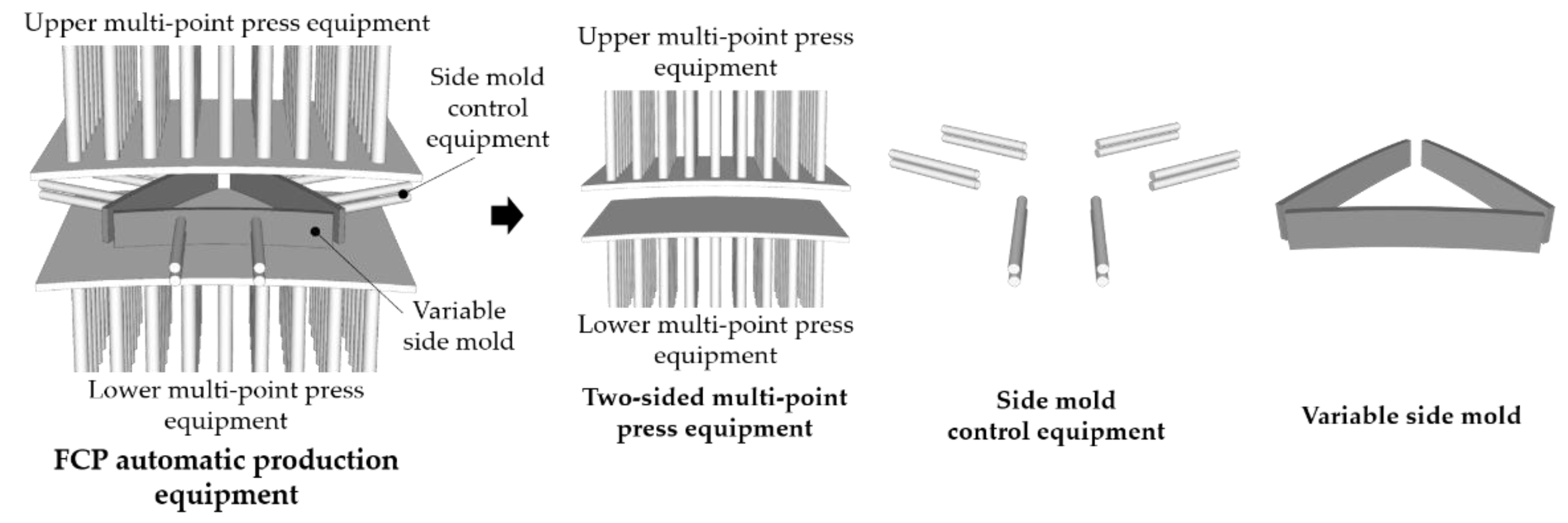
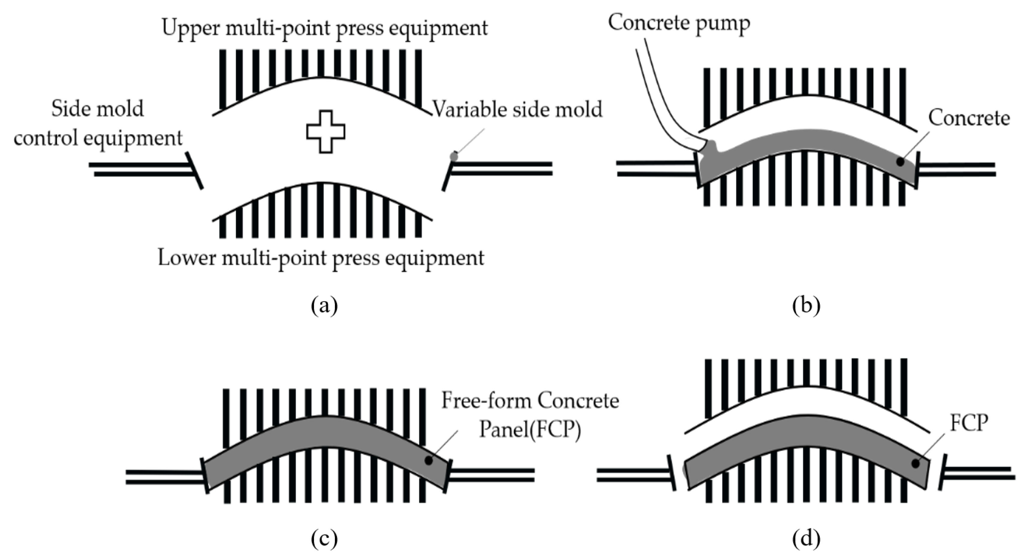
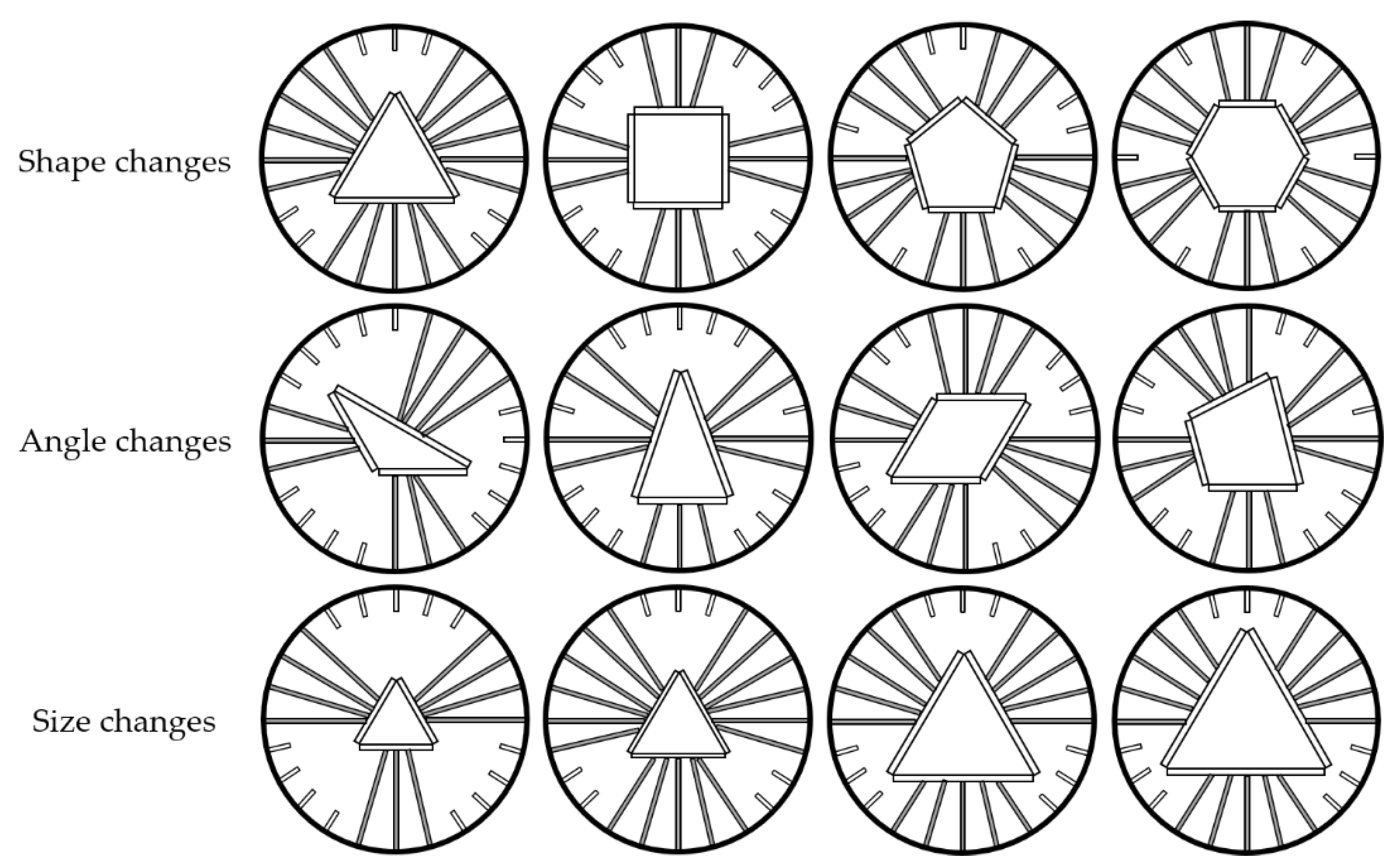
3. Concept of FCP Automatic Production Technology

FCP automatic production equipment can automatically produce panels. This equipment consists of two-sided multi-point press equipment, side mold control equipment, and variable side mold, as shown in Figure 1. Two-sided multi-point press equipment consists of upper multi-point press equipment and lower multi-point press equipment. This forms a mold to implement the curved surface of the top and bottom of the panel. Side mold control equipment can produce various shapes of FCPs and can adjust the side angle of the panel. Variable side mold can transform the mold according to the side curvature and shape of the panel.
FCP’s manufacturing process can be divided into four categories: combination, injection, curing, and demolding, as shown in Figure 2. First, the upper, lower, and side mold equipment is combined according to the shape of a panel to be manufactured. Then, concrete is injected into the mold. The injected concrete is compressed and cured by the upper multi-point press equipment. Finally, the manufacture is completed by removing the mold of the FCP that has been cured.

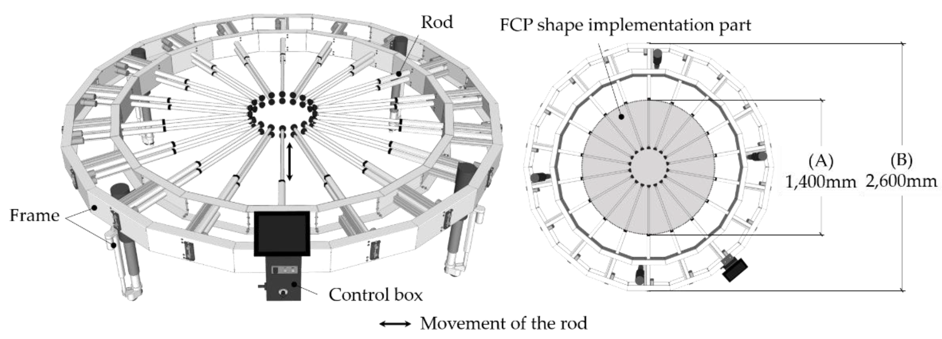
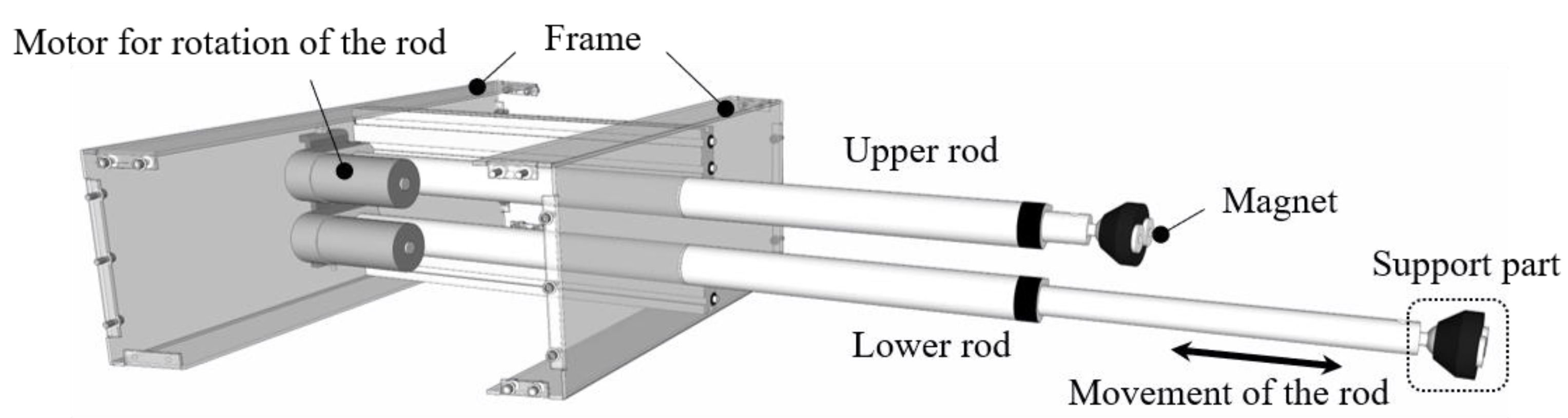
4. Development of Side Mold Control Equipment

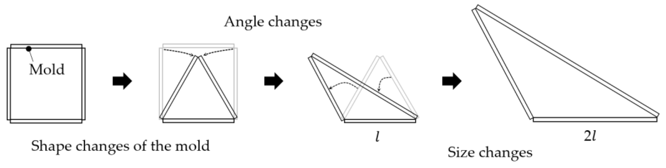
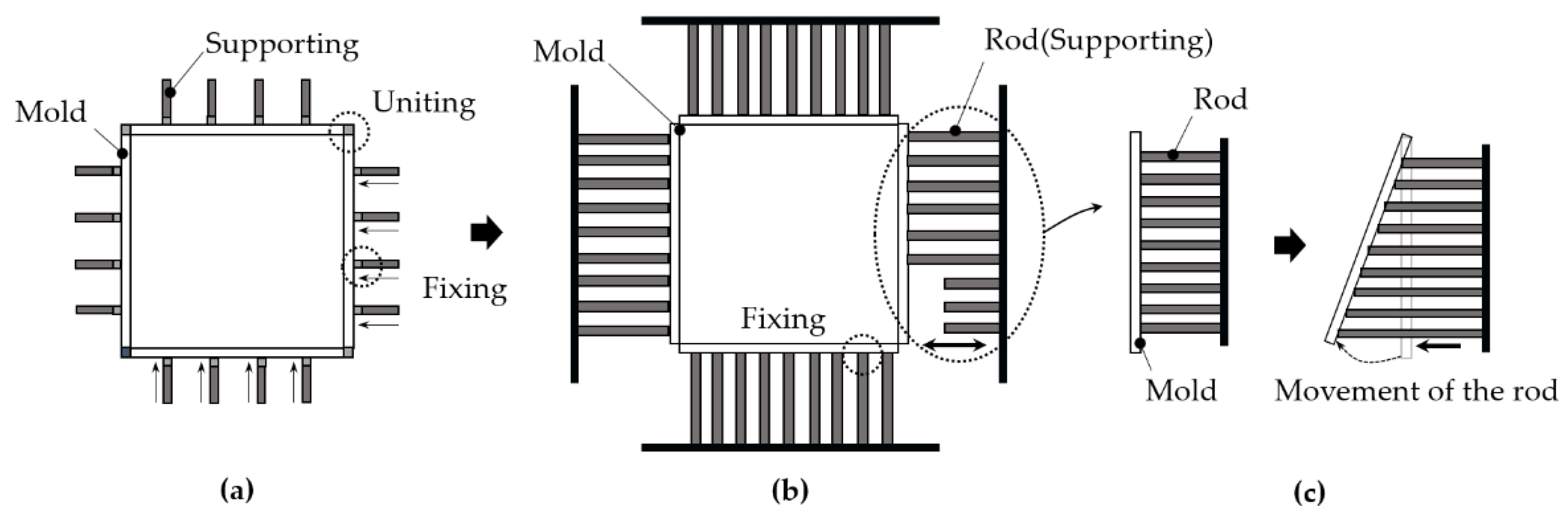
4.1. Requirements Analysis

The reuse of molds requires flexible transformation of the mold. For example, a square mold should be able to change into a triangle, as shown in Figure 3. That is, in order to reuse the mold, the side mold control equipment must be able to change the shape of the mold. In addition, this equipment should be capable of transforming the mold to produce various shapes of panels. Even if the panels are all polygons, the panel’s shape may vary depending on the angle. Triangles are divided into regular, acute, and obtuse-angled triangles, depending on the angle they form. They are all triangles, but the panels are not the same since they all have different angles. Therefore, this equipment should be capable of varying the angle of the mold. Furthermore, the panel used for the curved surfaces may vary in size depending on the building or the curved surface position. There may be size changes, even when the shape and angle required by the panel are the same. Therefore, the side mold control equipment should change the shape, angle, and size of the mold to cope with panel diversity.

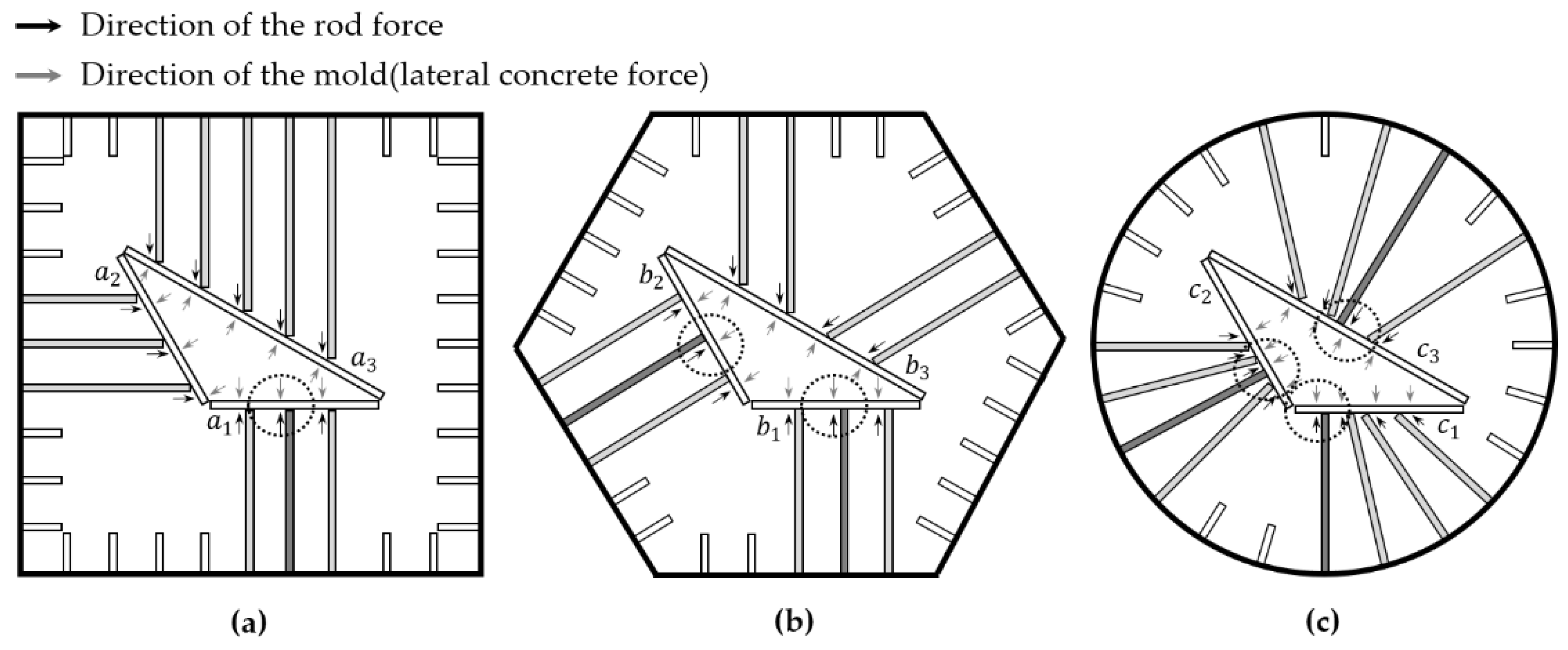
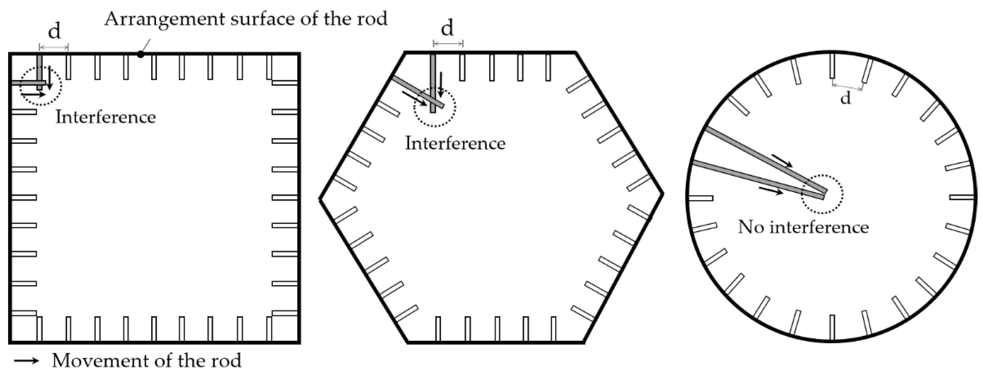
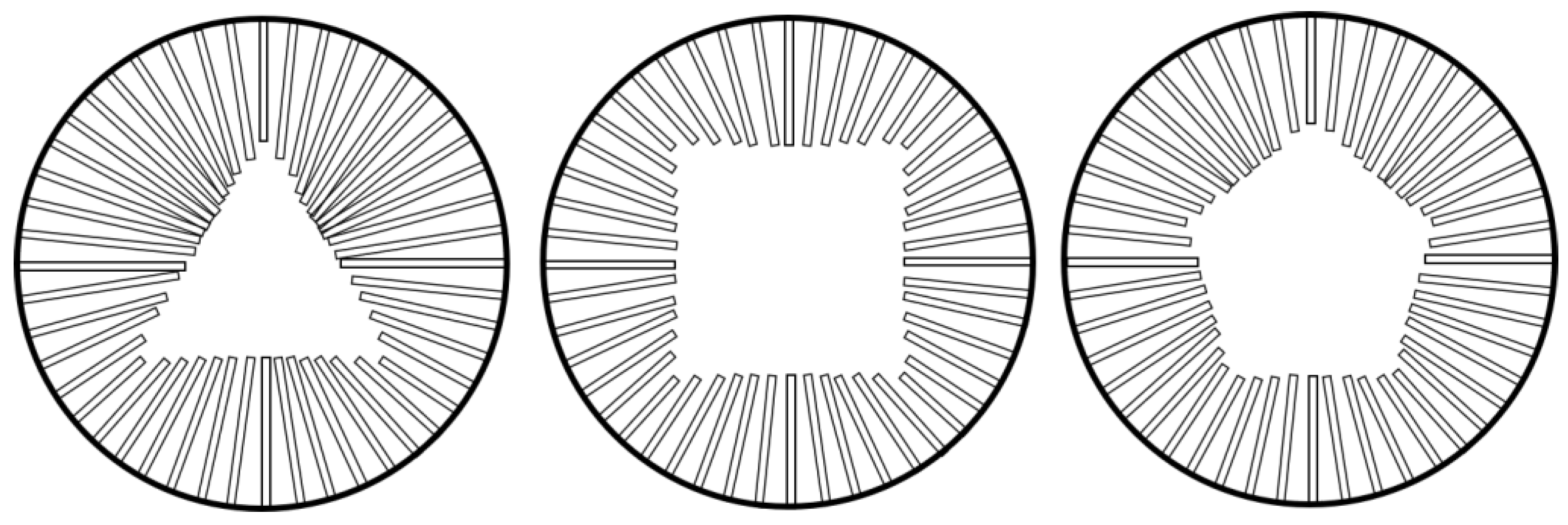
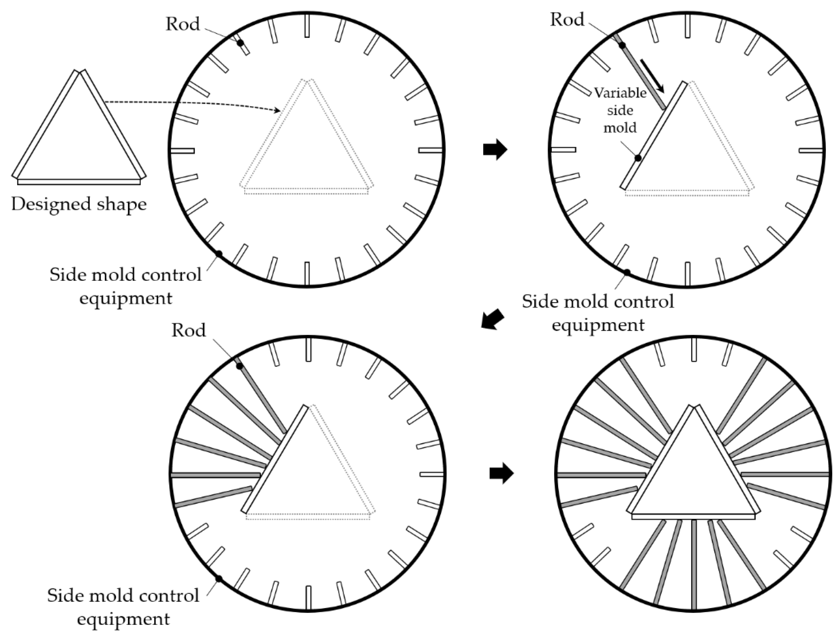
4.2. Equipment Design

The conventional method forms a mold to fit the shape of the manufacturing panel and unites them together to prevent them from being distorted, fixed by supports. The supports hold the mold so that they do not move. This method does not allow the mold to transform because there is no movement of the rod, so the mold cannot be reused. The movement of the rod is necessary to reuse the mold. Therefore, as shown in Figure 4, the concept of the rod is applied to the side mold control equipment. The rod was applied as a support to hold the mold and changed the mold’s shape by movement of the rod. This can produce various shapes of FCP molds.
The arrangement of the rod is one of the equipment development’s critical requirements. The rod transforms the mold through movement. The force corresponding to the lateral pressure varies depending on the angle between the rod and mold. This force disturbs strong fixing of the rod and mold. If the angle between the rod and mold are 90°, as shown in Figure 5, the force’s direction is applied horizontally, strongly fixing the mold. However, when the angle gets further from 90°, the force corresponding to the lateral pressure is reduced, meaning it reduces the fixing force of the mold. Therefore, depending on the panel’s shape, the rod needs the proper arrangement so that the mold can be correctly fixed in any position.
The importance of the rod’s arrangement can also be explained by lateral pressure. The rod should be capable of securing the mold firmly to prevent the mold’s distortion due to the concrete’s lateral pressure. To hold the mold, the direction of the rod and mold (lateral concrete force) must be horizontal. For example, if the FCP is manufactured in a triangle, as shown in Figure 6, the rod must be fixed on three sides of the triangle mold. Multiple rods should be fixed to each mold and at least one rod must be fixed to the mold for strong fixation. Accordingly, the rod was placed in a square, hexagonal, and circle to select the arrangement of the rod.
In the case of a square arrangement, three rods hold mold a1 vertically. However, a2 and a3 have no rods that hold vertically. A hexagonal arrangement has one or more rods that hold b1 and b2 vertically, but no rods that hold b3 vertically. The circle arrangement has at least one rod that holds c1, c2, and c3 vertically. This allows the rod to strongly fix the mold and prevent distortion by the lateral pressure of concrete.
The circle arrangement of the rod causes no interference from the rod. There is interference for each arrangement due to the angle at the arrangement surface formed, as shown in Figure 7. It is possible to check the interference when arranging the rod at the same interval (d) on the arrangement and moving the rod of the part where the arrangement is surface adjacent. Rectangular and hexagonal arrangements result in the interference, even in a small movement or rod due to the angle at which the arrangement surface formed. However, the circular arrangement does not have the arrangement surface angle, and the movement of rod causes no interference. Thus, arranging the rod in a circle is the most suitable arrangement type for side mold control equipment.
Rods arranged in a circle enable the reuse of the mold, as shown in Figure 8, because various shapes can be implemented only with automatic movement of the rod. Therefore, this study developed side mold control equipment using the circle arrangement and the concept of the rod. The side mold control equipment implements the shape of FCP through the process shown in Figure 9. First, the designed shape of FCP is inputted into the side mold control equipment. Then, the distance of the rod that implements the inputted design shape is checked. The rod is moved the checked distance. All of the rods fixing the mold are moved. This method can change the shape, angle, and size of the mold and it satisfies all of the requirements. Side mold control equipment can manufacture a variety of FCPs, as shown in Figure 10.

4.3. Side Mold Control Equipment

Side mold control equipment consists of rods, a frame, and a control box, as shown in Figure 11. (A) is the FCP shape implementation part, which produces various shapes of the panel through the movement of rods. The diameter of (A) is 1400 mm, and (B), the total size of the equipment, is 2600 mm.
The rods move automatically and implement the shape of the FCP. The circle was divided into 18 sections, a total of 36 rods were arranged, with 18 at the top and 18 at the bottom. It was determined that the number of rods to implement various shapes was appropriate to manufacture the FCP, and two rods were arranged at the top and bottom of each zone. Each rod moves precisely back and forth according to the motor’s number of rotations and up to 500 mm. The rods manufacture a variety of panels through precise movements within the FCP shape implementation. The rod holds the side mold. As shown in Figure 12, the support part of the rod is magnetized, making it easy to attach the side mold. However, depending on the panel’s shape, the rod support and mold is not parallel, thus disturbing strong fixation. For a stronger fixation, a ball bearing was used. As shown in Figure 13, it allows the support part of the rod to rotate. As the rod is arranged in a circle, the frame is made in a circle. The four legs move vertically up to 300 mm. The control box allows the overall operation of the equipment and individual numerical control of the rod. All members of the equipment were firmly fixed. However, since rotation of the internal one and bending of the upper and lower rods may occur when producing large-sized members, the equipment can be strengthened by reinforcing structural cross-bracing elements. Variable side molds are manufactured by attaching steel plates together using bolts and metal spacers.

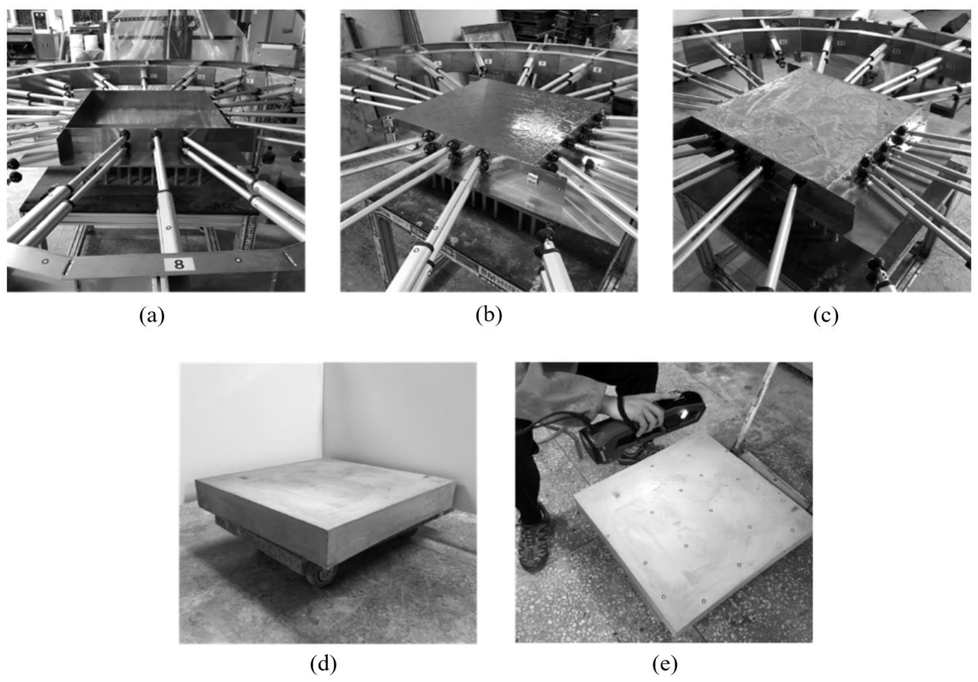
5. FCP Manufacturing Experiment

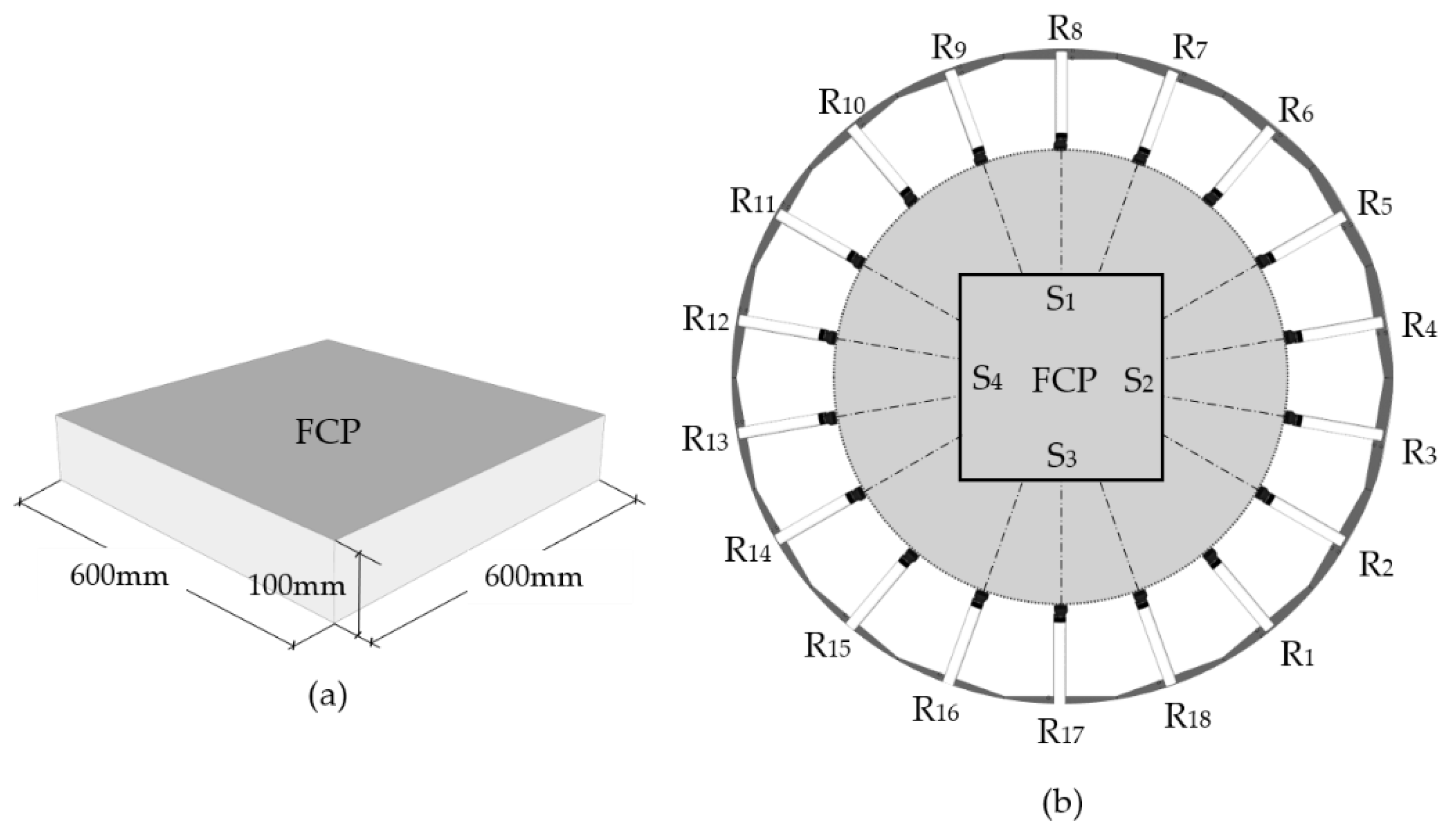
5.1. Equipment and Panel Specifications

The production range of FCP using the equipment was identified. The largest size of a triangle panel allows the length of one side to be 1212 mm and the smallest size allows the length to be 691 mm. The largest size of a rectangle panel allows the length of one side to be 989 mm and the smallest size allows the length to be 400 mm. The FCP was designed to be 600 mm × 600 mm × 100 mm as in Figure 14a based on the range of a rectangle. The shape located at the center of the shape implementation part to check the rods to be operated (b). S1 and S3 operated three rods, while S2 and S4 operated four rods. The operation value of the rods was measured as shown in Table 1. The operation values of the rods fixing S1 and S3 were the same and S2 and S4 were the same.
As shown in Figure 15, the side mold control equipment’s rod was moved to combine the side mold, and the lower mold was installed. After curing the mortar, the mold was removed. Finally, the manufactured FCP was 3D scanned.

5.2. Lateral Pressure on the Formwork

The thickness of the free-form concrete panels is generally in the range of 20 mm to 50 mm. In this study, the thickness of the panel for the experiment was set to the maximum size (100 mm). Mortars (W/C of 40%) were cast in the combined mold. When calculated with the unit weight (24 kN/m3) of the normal-weight concrete used in this experiment and the height of the panel (0.1 m), the lateral pressure was estimated to be 2.4 kN/m2. If the panel is made of lightweight concrete, the lateral pressure will be lower.

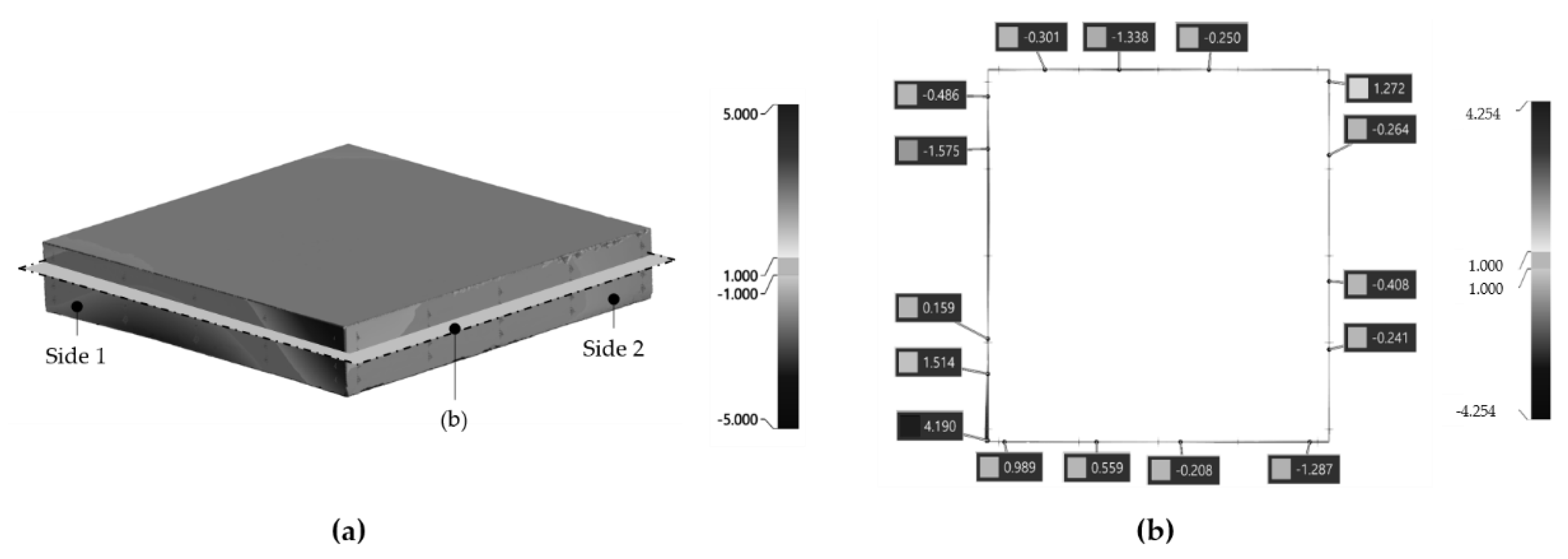
6. FCP Shape Error Analysis

Quality inspection of the FCPs was conducted to ensure that the FCP were manufactured correctly according to the designed shape. It is difficult to identify the FCP shape errors visually. Therefore, VXInspect, a quality inspection program, was used to analyze the errors. The manufactured FCP was scanned and the errors between the designed shape and scan data were compared.
FCP shape errors on the panel’s side will result in construction errors when assembling them. However, some errors should be accommodated because it is impossible to make a perfect match due to the nature of the free-form construction, which manufactures panels of several meters in size. There are no specific regulations on the errors allowed for free-form concrete panels. In this study, the side angle and the side surface of the panel were set as the quality standard items. There is no quality standard for the angle of the panel. Therefore, this study set the allowable errors below 0.1° to ensure the precision of shapes. The side surface was set below 3%, which is the error allowable for the thickness of walls in the Korean architectural regulations. Therefore, the side error in this study was 3 mm, which was less than 3% of 100 mm in thickness. For the FCPs’ side angle error, the side angle of the designed shape and scan data was compared. As shown in Table 2, the maximum angle of all the XY, XZ, and YZ planes on the side of the panel, and the overall angle taking them all into account was 0.037°, satisfying the quality reference angle presented in this study to within 1°.
Next, as shown in Figure 16, the side error was analyzed. A total of 80 nodes were designated in four surfaces, 20 nodes side by side. The analyzed error had directionality. Based on the designed shape, the error had a vector value of (+ã) in the outside direction or a vector value of (−ã) in the inside direction. Therefore, the allowable error of side should be within ±3 mm in this study. The minimum value in Table 3 represents the maximum error in the direction inside the designed shape. The minimum error was measured to be −2.471, and the maximum error was measured to be 4.957 mm. The maximum error was out of the error range suggested in this study, which caused errors due to the failure to fully level the side mold control equipment during the experiment. However, side errors excluding this section were smaller than ±3 mm.
As shown in Table 3, errors were measured excluding specific section. The minimum error was −2.471 mm and a maximum was 1.472 mm. This result was within the error range of ±3 mm. As a result, the FCP manufactured by side mold control equipment satisfied the allowable error.

7. Conclusions

In this study, side mold control equipment was developed to produce FCPs of various shapes. In the equipment, the rods operate automatically to support the side mold. The rods are arranged in a circle to support any shape of mold. The circle arrangement has no interference of rods and strongly fixes any shape of molds. In addition, the equipment automatically manufactures various shapes. The designed shape was inputted into the side mold control equipment, and the number of rods and the range were checked. Then, all the rods that can fix the molds were moved and the shapes were implemented. Since this equipment is a technology that manufactures various shapes, the shape errors may occur when manufacturing FCP. The errors were verified by analyzing the side angle and side error of FCP. First, the allowable error of side angle should be within 0.1° according to the precision of shapes. The maximum error of side angle was 0.037°. Next, the allowable error of the side surface should be within 3 mm (3%) according to the Korean architectural regulations when setting the thickness of FCP at 100 mm. The error was within 3 mm, smaller than the allowable error suggested by the study. The side mold control equipment was capable of manufacturing the FCP precisely. Furthermore, it was able to manufacture FCPs automatically without manpower. However, this study analyzed the errors for only one shape. Therefore, it is necessary to verify the ability to manufacture various shapes. Additionally, it is very important to manufacture the curved shapes precisely. Therefore, additional studies are needed to solve these issues.

Author Contributions

Conceptualization, J.Y. (Jiyeong Yun) and D.L.; Investigation, K.J. and J.Y. (Jongyoung Youn); Writing—original draft preparation, J.Y. (Jiyeong Yun); Writing—review and editing, D.L. All authors have read and agreed to the published version of the manuscript.

Funding

This work was supported by the National Research Foundation of Korea(NRF) grant funded by the Korea government(MSIT) (No. 2020R1C1C1012600).

Acknowledgments

This work was supported by the National Research Foundation of Korea (NRF) grant funded by the Korea government (MSIT) (No. 2020R1C1C1012600).

Conflicts of Interest

The authors declare no conflict of interest.

References

  1. Kim, S. Classification and Optimization of Irregular Shaped Building Panels by Fabrication Methods-Focused on Dongdaemun Design Plaza and Park. Master’s thesis, Yonsei University, Seoul, Korea, 2009. [Google Scholar]
  2. Lim, J.; Ock, J. A Study on the Optimization of the Free-Form Buildings Façade Panels. Korean J. Comput. Des. Eng. 2014, 19, 91–102. [Google Scholar] [CrossRef]
  3. Ryu, J.; Moon, J. A Study on Classification of the Panelizing for Architectural Freeform Surfaces and the Optimization of Panelizing. J. Korea Acad. Ind. Coop. Soc. 2013, 14, 4616–4626. [Google Scholar] [CrossRef] [Green Version]
  4. Desert Rose Made of Concrete-National Museum of Qatar. Available online: https://www.bft-international.com/en/artikel/bft_Desert_rose_made_of_concrete_-_National_Museum_of_Qatar_3478877.html (accessed on 1 March 2020).
  5. Architectural Details: Jean Nouvel’s National Museum of Qatar. Available online: https://architizer.com/blog/practice/details/national-museum-of-qatar/ (accessed on 1 January 2020).
  6. All about the National Museum of Qatar: Museum with a Heart. Available online: https://www.designcommunication.net/architecture/all-about-the-national-museum-of-qatar-museum-with-a-heart (accessed on 1 March 2020).
  7. Lee, D.; Jang, D.; Kim, S. Production Technology of Free-form Concrete Segments using Phase Change Material. Int. J. Adv. Comput. Sci. Appl. 2014, 4, 202–205. [Google Scholar]
  8. Lee, D.; Lee, S.-G.; Kim, S. Composite Phase-Change Material Mold for Cost-Effective Production of Free-Form Concrete Panels. J. Constr. Eng. Manag. 2017, 143, 4017012. [Google Scholar] [CrossRef]
  9. Mandle, P.; Winter, P.; Schmid, V. Free Forms in Composite Constructions, The New House of Music and Music Theatre in Graz; ECCS European Convention for Constructural Steelwork: Brussels, Belgium, 2008; pp. 1209–1214. [Google Scholar]
  10. Lindsey, B.; Gehry, F. Digital Gehry. Englische Ausgabe. Material Resistance Digital Construction; Springer Science Business Media: Berlin, Germany, 2001. [Google Scholar]
  11. Toyo Ito & Associates. Meiso no Mori Crematorium Gifu; SCRIBD: San Francisco, CA, USA, 2006; pp. 1–11. [Google Scholar]
  12. Schipper, H.; Janssen, B. Manufacturing double-curved elements in precast concrete using a flexible mould: First experimental results. In Proceedings of the FIB Symposium, Concrete Engineering for Excellence and Efficiency, Prague, Czech Republic, 8–10 June 2011. [Google Scholar]
  13. Verhaegh, R. Free Forms in Concrete Fabric. Master’s thesis, Eindhoven University of Technology, Eindhoven, The Netherlands, 2010. [Google Scholar]
  14. Oesterle, S.; Vansteenkiste, A.; Mirjan, A. Zero Waste Free-Form Formwork. In Proceedings of the Second International Conference on Flexible Formwork, Bath, UK, 27–29 June 2012. [Google Scholar]
  15. Seo, J.; Hong, D. 3D Cutting Machine of EPS Foam for Manufacturing Free-Formed Concrete Mold. J. Korean Soc. Precis. Eng. 2017, 34, 35–39. [Google Scholar] [CrossRef]
  16. Sim, J.; Kim, H.; Park, K.; Kim, C.; Hong, D. Manufacturing Automation System of Freeform Concrete Formwork Using S-LOM Method. J. Korean Soc. Precis. Eng. 2020, 37, 43–50. [Google Scholar] [CrossRef]
  17. Jeong, K.; Yun, J.; Kim, K.; Lee, D. Development of Operation Technology and Two-Sided Multi-Point Press Equipment for Improving Accuracy of FCP. Test Eng. Manag. 2020, 83, 59–64. [Google Scholar]
  18. Kim, S.; Son, S.; Lee, D. Development of Sustainable Production Technology of Free-Form Concrete Panels Using a Multi-Point Press CNC Machine. Sustainability 2021, 13, 1990. [Google Scholar] [CrossRef]
Figure 1. Configuration of FCP automatic production equipment.
Buildings 11 00175 g001
Figure 2. Process of manufacturing FCP: (a) Mold combination; (b) Concrete injection; (c) Concrete compressing and curing; (d) Demolding.
Buildings 11 00175 g002
Figure 3. Requirement of the mold.
Buildings 11 00175 g003
Figure 4. Applying the concept of rod: (a) Conventional mold; (b) Applying the concept of rod to mold; (c) Rotating the mold by the movement of the rod.
Buildings 11 00175 g004
Figure 5. Force according to the angle of the rod and mold.
Buildings 11 00175 g005
Figure 6. Direction of force between the rod and mold according to arrangement type: (a) Square arrangement; (b) Hexagonal arrangement; (c) Circle arrangement.
Buildings 11 00175 g006
Figure 7. Interference according to the arrangement of the rod.
Buildings 11 00175 g007
Figure 8. Circle arrangement to implement the shapes.
Buildings 11 00175 g008
Figure 9. Concept of the side mold equipment.
Buildings 11 00175 g009
Figure 10. Side mold control equipment that implements various shapes of FCP.
Buildings 11 00175 g010
Figure 11. Side mold control equipment.
Buildings 11 00175 g011
Figure 12. Configuration of the rod.
Buildings 11 00175 g012
Figure 13. Rotation of the rod.
Buildings 11 00175 g013
Figure 14. Design for FCP production: (a) Designed shape; (b) Operating rod.
Buildings 11 00175 g014
Figure 15. Process of manufacturing FCP with side mold control equipment: (a) Mold combination; (b) Mortar casting; (c) Curing; (d) Demold; (e) FCP 3D scan.
Buildings 11 00175 g015
Figure 16. Analysis method of FCP shape errors: (a) Scan data; (b) Cross section of scan data.
Buildings 11 00175 g016
Table 1. Operating distance of the rod that implements the FCP shape (unit: mm).
R1R2R3R4R5R6R7R8R9
0.0353.6395.4395.4353.60.0380.7400380.7
R10R11R12R13R14R15R16R17R18
0.0353.6395.4395.4353.60.0380.7400380.7
Table 2. Side angle error of the FCP (unit: °).
Side 1Side 2Side 3Side 4
∠XY plane0.0040.0030.0010.001
∠XZ plane0.0010.0050.0210.000
∠YZ plane0.0100.0010.0000.037
All0.0100.0030.0210.037
Table 3. Side error of FCP (unit: mm).
Side 1Side 2Side 3Side 4AllSide Error Excluding Particular Section
Min.−2.471−1.367−0.797−1.429−2.471−2.471
Max.4.9571.1351.2781.4724.9571.472
Mean.0.342−0.0860.1430.0950.123−0.084
S.D.2.2180.9170.7660.9211.3130.964
Publisher’s Note: MDPI stays neutral with regard to jurisdictional claims in published maps and institutional affiliations.

