1. Introduction
Pneubotic structures in architecture are quite a recent type of structures created through a combination of pneumatic and robotic components into a single structural type suitable for constructing lightweight and adaptive architectures. Pneubotic is thus a word formed by combining the words pneu(matic) and (ro)botic into a single compound word.
Pneubotic structures are a part of architectural robotics—a field with three main aspects: robotic fabrication of building components, robotic construction, and robotic structures—each widely and intensely researched. Universities and institutes in Europe, and in the world often speculate, explore, and investigate practical applications of robotics in architecture. According to Picon, robotic arms are often used for structural research in many architecture schools, and robotic fabrication enables rapid prototyping and small-scale production of sophisticated components that could compete with repetitions and mass production [
1]. Robots are also used to investigate the possibilities of building complex structures like those investigated at ETH Zürich using single robots or cooperative robotic building [
2] or even (aerial) swarm robotics for construction [
3]. Apart from producing and constructing with robots, structures themselves can be robotic to achieve desired properties or effects. For instance, “The SmartShel” robotic shell built by ILEK institute in Stuttgart uses actively adaptable supports to adjust the shell geometry for optimal use of the material resulting in only 4 cm thick wood shell spanning 10 m [
4]. Another aspect of “robotic” structures are passive programmable material systems like humidity activated “Hygroskin”—a research project by Menges [
5], or adaptive bimetal shading systems by Sung [
6]. Advancements in architectural robotics, argues Picon, challenge designers to think in terms of true spatiality, thinning the line between objects and processes, stability and instability, and bring the complex and the multiple as a more natural basis for design [
1].
Pneumatic structures, on the other hand, emerged in form of air balloons and air ships in the eighteenth century. They were used for military purposes in the World War II and since the mid twentieth century have entered the civilian use. They were used to construct lightweight structures ranging from small and temporary spaces like mobile venues or pavilions to large span roofs for stadiums, greenhouses, or hangars [
7]. Because of their small weight and transportability, they are often used for expeditions and space exploration [
8], or for emergency structures like for instance “inflatable concrete canvas shelter” [
9]. They are sometimes used for construction of permanent structures like a formwork [
10] or molds for creation of rigid blobs [
11]. Application range of pneumatic structures today is very wide indeed.
The development of computation and new materials, sensors, and controllers, coupled with the desire for adaptive lightweight structures has resulted in the emergence of pneubotic structures. Pneubotic structures followed the development of soft robots—i.e., robots with a distinguishing feature of articulating motion through large deformation of their robotic body parts made of stretchable materials.
Soft robots can be actuated in different ways: by using compressed air (with positive and/or negative air pressure) or fluids (for underwater applications), by using dielectric elastomers or shape-memory alloys, most widespread being those pneumatically actuated. They can be made from elastomers like silicon, rubber, dissolvable and biodegradable materials, various biomaterials, and the like. They are quite difficult to model and control because there is no general theory of controlling unconstrained and hollow continuum structures with nonlinear deformations [
12]. Other notable characteristics of soft robots are the advantage of material compliance to achieve adaptable soft touch; simplicity and low cost; low maintenance; light weight, and high stiffness to weight ratio; high strength (especially of those composite materials that can allow for the creation of soft, “ultra-soft”, and “hard-soft” robotics); ease of combining with hard parts into hybrid robots; nonlinear behavior seen as an advantage that allows for the generation of complex motions using very simple actuation; ease of sterilization; resistance to temperature; resistance to chemical corrosion; biocompatibility; and technological simplicity and others [
13]. Soft robots are typically small, and systems of elements made from elastomers that could be mass produced and used for architectural purpose include research projects like “Adaptive Pneumatic Frameworks”—that merges “computation, soft actuation, and research of soft synthetic materials for the exploration of adaptive and responsive behaviors in architecture” [
14]. The speculations on the idea of “softening the architecture through machines” (many of them air driven) has been investigated by Wichart in his PhD thesis “The Architecture of Soft Machines” to propose an embodied architecture based on soft human-machine interaction [
15]. There are examples of larger soft robots, like those in experimental structures “M3 Robots”, “Ant-Roach”, and “Walking Elephant” from Otherlab [
16], and even to the scale of the building like “Airtecture” pavilion, which uses soft linear actuators on frames constructed from inflatable beams and columns to actively adapt to the changing environment [
17].
Pneumatically actuated structures in art and architecture can be constructed using both hard and soft parts and actuators. For instance, linear pistons that actuate structures like “Hyposurface” [
18], and “InteractiveWall” [
19] (
Figure 1) are hard pneumatic actuators. However, in the field of soft robotics, it is precisely soft parts and actuators that are the focus of scientific research. The soft actuator can be linear, like a soft muscle used for actuating “Muscle Tower 2” [
20] (
Figure 1), and volumetric—the one that can simultaneously serve as a structural element and as an actuation element. Soft linear actuators are for instance used by Chen in his research focused on the development of an open-source pneumatic toolkit for kinetic structural research and application [
21]. When the outer fabric of the soft muscle is differentially knitted, it can turn it into an actuator with highly articulate shapes and complex motions [
22]. Through adaptable inflation of pneumatic structural and actuating parts of the soft robotic body manifested is the capacity to change shape of the robot and produce its motion. Hence, such elements can simultaneously serve to form and to transform the structure. The idea of a body is already widespread and used in robotics, both hard and soft, but in case of architectural robotics it still needs to be adopted wide and well.
Experimentation with pneumatically adaptable structures in art and architecture, dating back to the 1960s and 1970s, can be found in cases like the “Dynamatt” installation by Fisher and Conolly [
23] (
Figure 1), “Prototype of varying morphology beam” by Prada Poole [
24] (
Figure 1), and others. Those were transformable pneumatic structures with volumetric actuators operated manually or automatically. Recently, with the development of new technical possibilities, specifically designed materials, electronical control and computing, and current artificial intelligence, full-blown pneumatic robotic structures have emerged. They can adapt or actively respond to unpredictable environments, as an individual body or a “living” collective of architectural bodies, like for instance the interactive architectures that have been constructed and tested in the interdisciplinary research project “Hyperbody” at the Technical University in Delft [
25]. Such structures can broaden the field of possibilities for cheaper, more robust, and less complex responsive and adaptable structures in architectural design.
When multiple soft elements join in one soft body, through adaptable inflation of an individual element, a group of elements, or all elements at once like project “Adaptive pneumatic” by Reparametrize Studio [
26], a complex articulation becomes possible, like those of living soft creatures, on a local, regional, or global structural level. Hence, they can become biomimetic pneubotic structures. Suppose they are made from same modular elements. In that case, they can become a product with a dualistic nature: modern or industrial, in their production process of large series of the same multiplicate, but also contemporary or postindustrial, in their actual state within the structure—in terms of a “repetition and difference” (here on an individual level of inflation) in relation to other elements (
Figure 2a). Structures can truly become indefinite in a way that they can continuously transform from one state of determination to another, thus corresponding to the definition of virtual and real, inline to Deleuze’s considerations of a differential element that form a structure as “its ‘virtual’ or ‘embryonic’ elements” [
27].
In this way, they are closer to living beings, where there is no ideal one, but every individual is a repetition of the same body plan with different intensities of its parametric values. The concept of a “body plan”, as discussed by DeLanda [
28], is present in architectural theory and contemporary parametric design techniques. It is borrowed from biology where species of the same phylum share the same body plan—their bodies are composed of the same parts connected in the same way, but parts themselves have different parametric values (length, width, etc.) like the bones in the limbs of mammals (
Figure 2b). A basic body plan is a reduced abstract expression of a structural body or body part from which various derivatives can be constructed—those that share the exact same body plan, and complex bodies composed of different basic body plans. This concept was examined and used in [
29], to obtain basic body plans as functional schemes or descriptive diagrams for the design of soft pneumatically adaptable and responsive structures in architecture.
This paper aims to investigate the actuation characteristics of basic body plans as determined in [
29] through the analysis of the construction of soft robots, soft adaptive structures in architecture and art installations, and the possibility of construction by using the modular spatial pneumatic unit element. In this paper, those established basic body plans are examined in their physical form—recreated by using same modular elements—to acquire insights that can inform the design and construction of complex soft pneubotic structures for architectural application.
2. Materials and Methods
For this (exploratory) research, an experiment was designed for the qualitative analysis of the actuation characteristics of different body plans. A set of basic body plans was constructed using simple pneumatic elements. Through manual inflation and deflation of elements, the effects on movements and transformations such as bending, lifting, tilting, rotating, or breaking were observed for each body plan. If the transformation or movement was visually registered, and controlled inflation produced controlled movement, the effects were noted. The schematic diagrams of basic body plans taken from the aforementioned article [
29] are shown in
Table 1, where they have been classified into four main types with further subdivisions, counting 8 basic body plans in total. These are: individual unit elements that can be indirectly connected (A); arrays of closely interconnected units (B), as linear (B1), planar (B2), and spatial arrays (B3); bodies consisting of flexible and expandable side (C1), flexible middle and expandable sides (C2), membrane with expandable core (C3), and finally “hard” parts with soft actuating expandable elements (D).
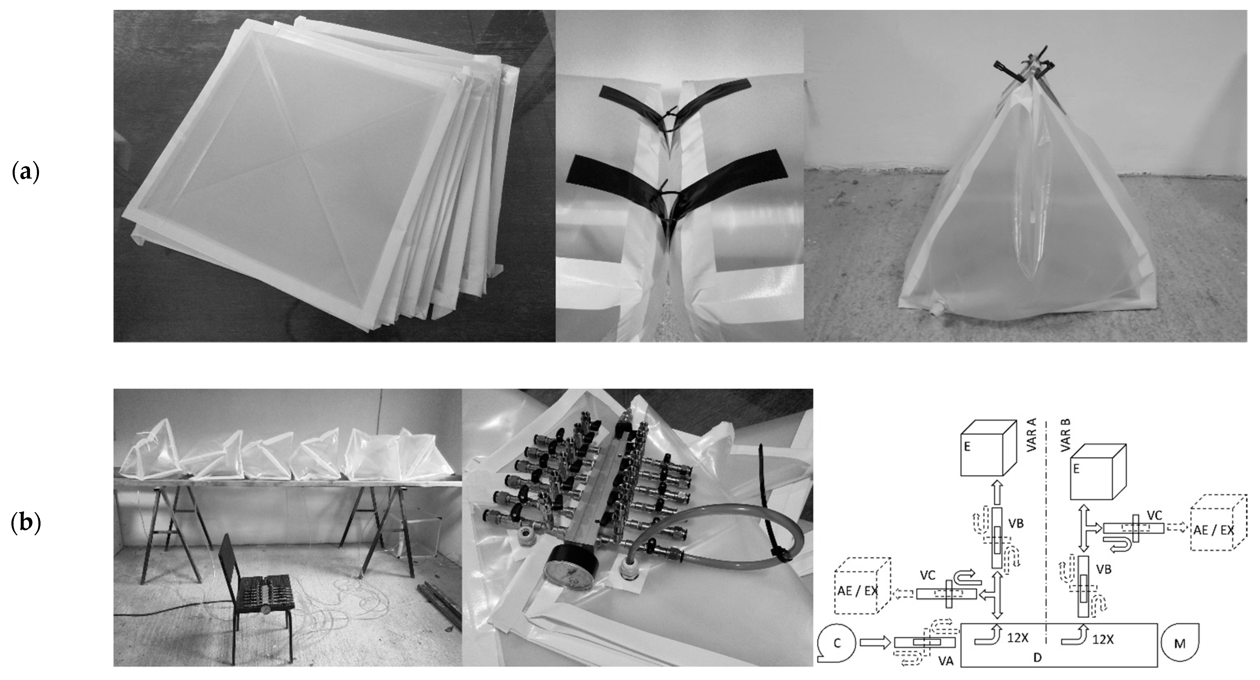
These basic body plans were physically reconstructed using up to 12 cube-shaped elements equipped with air inlets. A valve switch connected to an electric air compressor (model Einhell AirTech Euro 2500-2) with a 50 L capacity was used to control the inflation of the individual elements manually. Here, the soft modular element in the shape of a cube was chosen as it can equally connect in all three dimensions. The plain cubic form was chosen also to simplify its production from straight squares of polyethylene foil. The edge length of 50 cm was chosen to fit the quasi scale of architectural structures, since smaller element would more resemble small robots. Cube sizes like 15 cm × 15 cm × 15 cm and 30 cm × 30 cm × 30 cm were also considered, but 50 cm × 50 cm × 50 cm was finally chosen since it meant that smaller number of elements is needed for structures of the same size. It also meant that the air volume needed to run the experiment was still manageable for the compressor that was used. Different materials such as linen, polyvinyl, latex, were also considered, but those were abandoned because they would either deform too much, or else rip too easily. The polyethylene foil, used for covering greenhouses, was finally chosen as it best simulated foils of air cushions in architecture. Since the research focused on the transformation characteristics of basic body plans, chosen material proved to be a quite suitable approximation for modelling.
Squares were taped together into cubes by using a 48 mm wide fiber-reinforced universal adhesive duct tape to join the faces. The same tape was also used to form anchor points at individual edges approximately 10 cm away from the corners of the cubes. Connection of the cubes was achieved via plastic cable ties at the anchor points. Connecting all the points on the adjacent cubes’ touching faces resulted in a form where cubes shared a common face, as shown in type B basic body plans. By contrast, the asymmetric connection resulted in forming a zone of restricted expansion on the connecting side, and expandable on the opposite side, as shown in type C basic body plans. Further on, cubes folded into triangular prisms created actuation wedge elements needed to create type D basic body plan (
Figure 3a).
The cubes were filled with air through an opening made in one of the corners and fitted with 11 mm diameter plastic cable glands in which an 8/10 mm PVC flexible hose could be plugged into. The hoses were connected to an air distributor with valves through which the inflation and the deflation of individual elements were manually controlled (
Figure 3b).
Schematic diagram in
Figure 3b shows the used air distributor that was used (variant A). In it, the air from the compressor enters the main channel of the distributor D with 12 exits and with a manometer at the end. Each of its 12 exits had two additional valves. Valves B were used to let the air into individual elements, and valves VC were used as exhaust. Valves VC were here to allow (with additional attachments) for the connection of more than 12 elements if necessary. Individual elements were inflated through valves VB. The deflation was executed by closing the main valve VA and all the valves VB for elements that needed to stay inflated. Then the element(s) that needed to be deflated had their valve VB open, and any of the VC valves were used to let the air out. Then, valves VC were closed, valves VB open and air was again let in from the compressor through the main valve VA. Variant B of the same distributor is possible as an alternative that enables up to 12 elements to be inflated, and deflated individually without stopping the air flow through main valve VA. The pressure in the cubes was not measured because the focus of the experiment was to investigate the correlation of the functional schemes—basic body plans—and the capacities of individual body plans to change their shape and achieve movement. Air pressure used in general was low, since the structures were very lightweight, but high enough to lift a car (
Figure 4b). However, an ultimate pressure was measured while inflating the element until it burst at 1 bar, while pressure in the elements during experiments varied between 0.05 and 0.2 bar. It is shown in
Table 2 along with other physical properties for the elements.
A greater part of the tests was done on the bodies recreated by using only soft elements, while a lesser part was done on structures constructed by using a combination of rigid, flexible and/or tensile elements. Most of the tests were run in a protected indoor environment, on the ground or on an elevated surface, and mostly did not include external loading effects on the structure. The actuation was achieved through inflation of an individual element, of a group of elements, or all assembly of elements at once. To actuate the structures, only inflation and release of pressure was used. The descriptive qualitative analysis was carried out on different functional configurations of the unit elements, corresponding to the specific body plans.
4. Discussion
Based on the results from experimenting with this physical model, several things could be noted about the model as well as each basic body plan type.
This basic analysis showed only a fragment of the vast field of possibilities for the recreation of these basic body plan types because here are presented only some of their possible virtually multiplex physical manifestations.
Although limited to just 12 elements, the model was revealing enough to give sufficient insight to perspectives for applications and prospects for further research. For instance, very long chains of unit elements for linear bodies, or volume bodies with sides larger than three elements in case of C3, or sides larger than two elements in case of B3 types and alike were impractical to run manually or would need more than 12 elements. Some basic body plans were here reconstructed only in one, most obvious form, while others were omitted for the sake of other body plans that produced a greater variety of reconstructed forms. Although this may present a drawback, since not all possible reconstructions of basic body plans were covered, forms that were tested here covered all the main aspects.
Furthermore, since the modular unit element could be vacuumed to produce the actuation effect in some cases, it should be noted as a possibility for future research. This line of research was here omitted as well as the opportunity to use a modular element as a tension element since it would further expand the focus. These cases are left open as possibilities for further research. For instance, modeled on the experiments on “evolving soft robots with multiple materials” [
30], the construction of hybrid pneubotics of architectural scale consisting of active (inflatable or vacuumable) and passive (hard or soft) elements could be imagined.
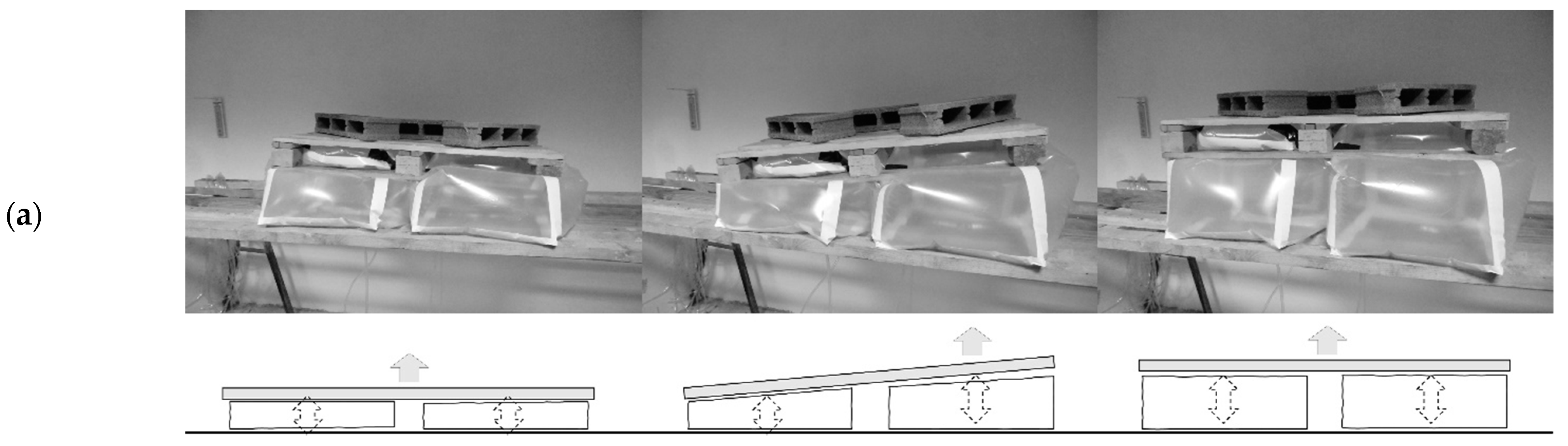
4.1. Basic Body Plan Type A
This body plan type allows the design of dynamic substructures adaptable to irregular and unstable terrains or base, with the ability to adaptably lift and tilt platforms. It could be possible to construct an active base for temporary structures in places where the impact of the structure on the ground must be minimal, and the structure should be removable without leaving traces. It also seems possible to design structures that can block or allow movement through space as needed, change the tilt of other structures, temporarily lift, or stabilize structures [
31], or otherwise protect vulnerable or damaged structures, equipment, and users.
4.2. Basic Body Plan Type B (B1, B2, and B3)
Thanks to many connections that ensure full contact of touching elements, this body plan resulted in a less pronounced capacity to change the shape of the developed form through additional inflation of cubes. Nevertheless, this may be regarded as less of a disadvantage when more robust structures need to be used. With additional stability elements, or springs, structures that can contract and expand [
32], or unfold could be constructed. The unfolding linear, planar, and spatial structural bodies of variable stiffness can be designed using this basic body plan.
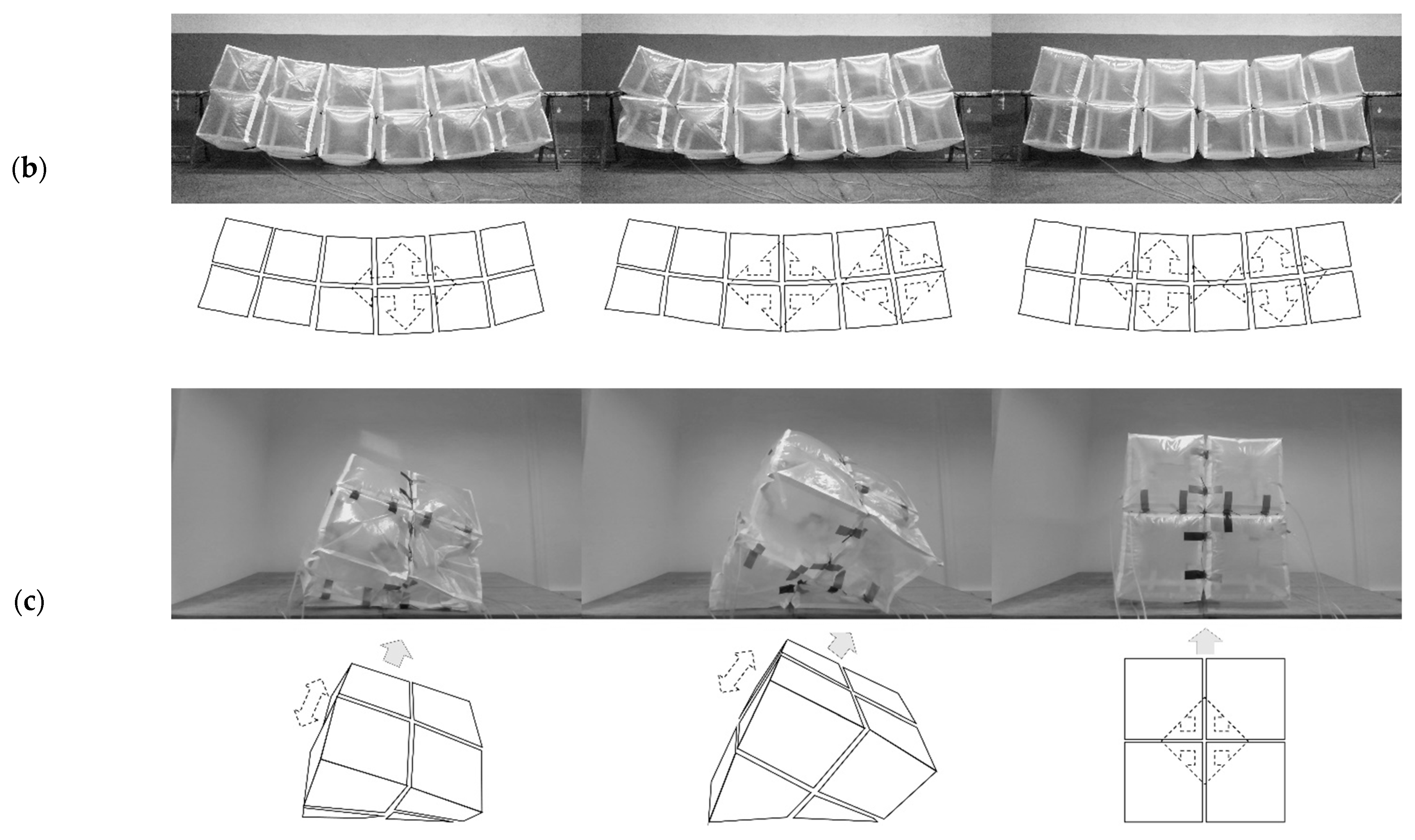
4.3. Basic Body Plan Type C1
This basic body plan showed the greatest degree of transformability. The possibility of the symmetrical and asymmetrical lifting of its ends enables the construction of structures that can bend to form a concave shape with lifting ends, or convex forms by lifting its central part, depending on the orientation of its flexible and expandable sides.
As a cantilever, this body plan could produce lifting with variable curvatures, concave and convex. It could also break at the deflated element. Such characteristics of this body plan suggest that it is possible to construct a structure that can lift its end while achieving adaptable curvature that could also be broken at a specific point.
The planar design of this body plan had the ability to adjust the bending of its surface in two directions, allowing for the construction of surface structures with complex spatially adaptable curvature.
The ability to lift parts of the structure and adjust the profile’s height and symmetry suggests the possibilities to design convex and concave shapes of adjustable curvature and height like domes and roof structures [
33]. This would enable the design of buildings with adaptable volume (for instance the volume of conditioned air) increasing it when they are fully occupied and reducing it in periods of a reduced or cold drive.
4.4. Basic Body Plan Type C2
Tests on the double sided planar and spatial pneumatic structures have shown that structures of this basic body plan can bend multi-directionally in plane and spatially. This indicates that it would be possible to construct structures capable of complex motions like bending and twisting, depending on the inflation of individual elements. This basic body plan type is like the basic body plan type B3, with the difference that the body plan type C2 can produce more intense effects while using fewer elements.
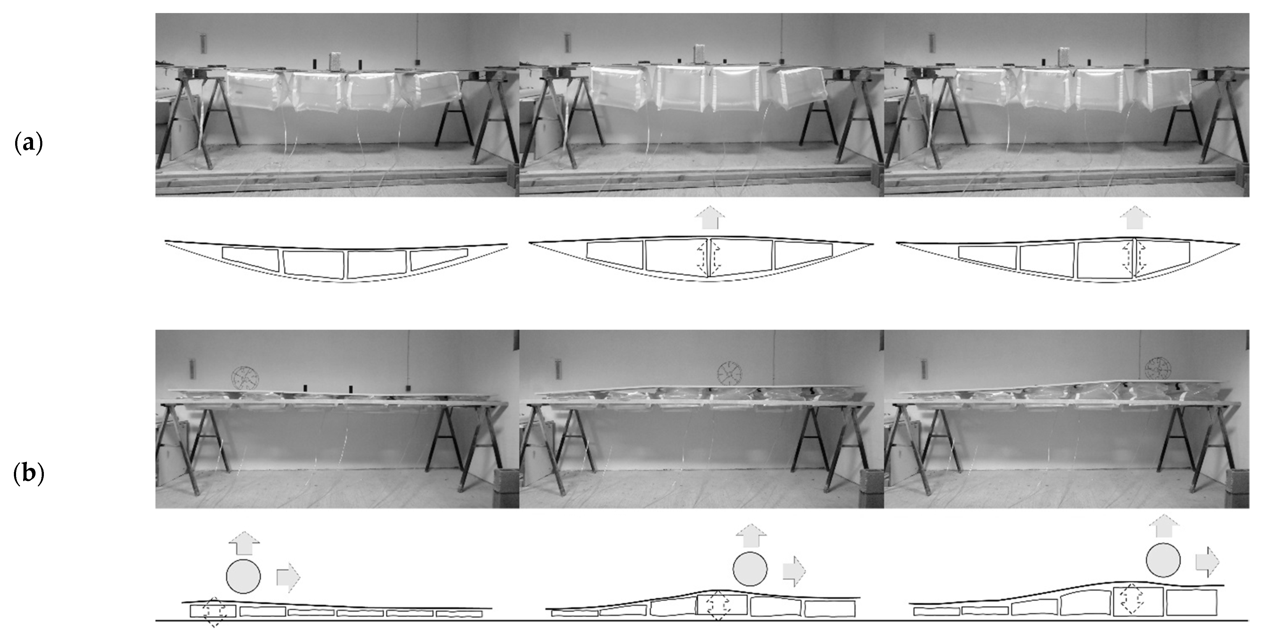
4.5. Basic Body Plan Type C3
A structure like tensairity beam demonstrated the capacity to change the curvature of the slender compression element symmetrically and asymmetrically, depending on the inflation of individual elements, suggesting that it would be possible to construct beam structures that could actively adapt their geometry to different cases of the live load position. Active curvature control could imply better structural response to the dynamic environment compared to classical tensairity structures.
Tests that were run on a ramp-like structure showed the possibility of moving the rolling object uphill by sequential inflation of individual elements or locally maintaining the horizontality of the surface below the rolling object. This body plan hence has the potential for constructing dynamic terrains and ramps that could be constructed in natural as well as within the existing built environment where there is not enough space to construct standard ramps with fixed geometry (especially in the case of heritage sites or protected buildings where they would have to be non-intrusive and reversible).
Furthermore, both basic body plans C2 and C3 present the opportunity to design double layer surface structures with bidirectional bending like roofs, dynamic suspended ceilings, or bridge structures with adaptable curvature. This opens new questions about this model’s nature and modular pneuobtics in general, questions like: what performances would the large roof structure of a combined body plan type C1 + B2 exert?
4.6. Basic Body Plan Type D
This basic body plan could adjust the angle between the two elements, thus allowing the potential design of self-erecting structures, structures that can lift, tilt, bend, rotate, or even walk [
34] for better adaptability. Testing the basic body plan type D with its “hard” parts replaced by body plan type C1 showed (when elements of type C1 inflated adaptably) the possibility to construct complex bodies where one can be present inside another as a “real virtuality” [
35] that comes to being only when certain criteria are met. Otherwise, they may stay “dormant”.
A short summary of basic characteristics of observed body plans and design opportunities they allow for is given in the
Table 3.
This further emphasizes the main distinguishing feature of pneubotic structures—the ability to constantly adapt to changes, like a structure in live constant “versioning” [
36], pass the virtual space of design software, much more similar to contemporary actively adaptable facades [
37], but in all subsystems of architectural structures. Mobile structures that can temporarily fill spaces or partition them to isolate groups of users like in hospitals, homes, or schools could be constructed using modular pneubotics. Coupled with supplementary apparatuses they can also serve as multifunctional structures that could cool or heat spaces or absorb noise in urban areas especially if they can move in pneumatic way. This direction for research is important one when different ways of temporary control of space and its parameters are needed.
Rigged with additional sensorial and computational power, this model could be easily turned into a research model for advanced actuation control methods for soft architectural pneubotic structures as well as for research in human-structural interactions, and load path management [
38].
Presented here are the general examples of design opportunities of pneubotics in the field of architecture, but it should be kept in mind that, since these structures are polytypic, they have a much wider field of possible applications. They can range from soft robotics, adaptable infrastructures (like acoustic fencing, dynamic dikes, and other devices), different transportation vehicles (planes with adaptive whing geometry), different protective installations, expedition vessels, as well as space exploration devices and shelters, and alike.
5. Conclusions
Structures that have been recreated and tested here in physical form have shown that the basic body plans could be used as a tool to translate the structural logic of small soft bodies and living beings into the scale closer to that of architectural structures. They are also a valid generative means for the construction of lightweight modular pneumatics that can be turned into actively adaptable pneubotics in architecture since it was possible to produce functioning physical object that correspond to the specified abstract schemes.
These tests have shown that modular pneubotics could be used for the design of structures that have the capacity to actuate similarly to those of soft living morphologies rendering them truly biomimetic. They can be load-bearing structures, building envelopes, protective structures, control structures, construction site robotics and others which means that modular pneubotics in architecture are a valuable structural polytype worthy of detailed future analysis.
Since this research analysis was limited to actuation characteristic and did not cover any details regarding the materials, construction, forces, pressures, actuation, electronic control, behavior algorithms, etc., further, more detailed research could be done on every specific body plan and its multiple physical manifestations to conclude about other aspects of soft modular pneubotics in architecture for each type.
Moreover, perhaps the most crucial research perspective is the possibility of combining several basic body plans into one complex body that could inherit the characteristics its constituent basic body plans.


