
Influence of Compressive Strength of Concrete on Shear Strengthening of Reinforced Concrete Beams with Near Surface Mounted Carbon Fiber-Reinforced Polymer

 ,
,
Abstract
:1. Introduction
2. Experimental Investigation
2.1. Materials
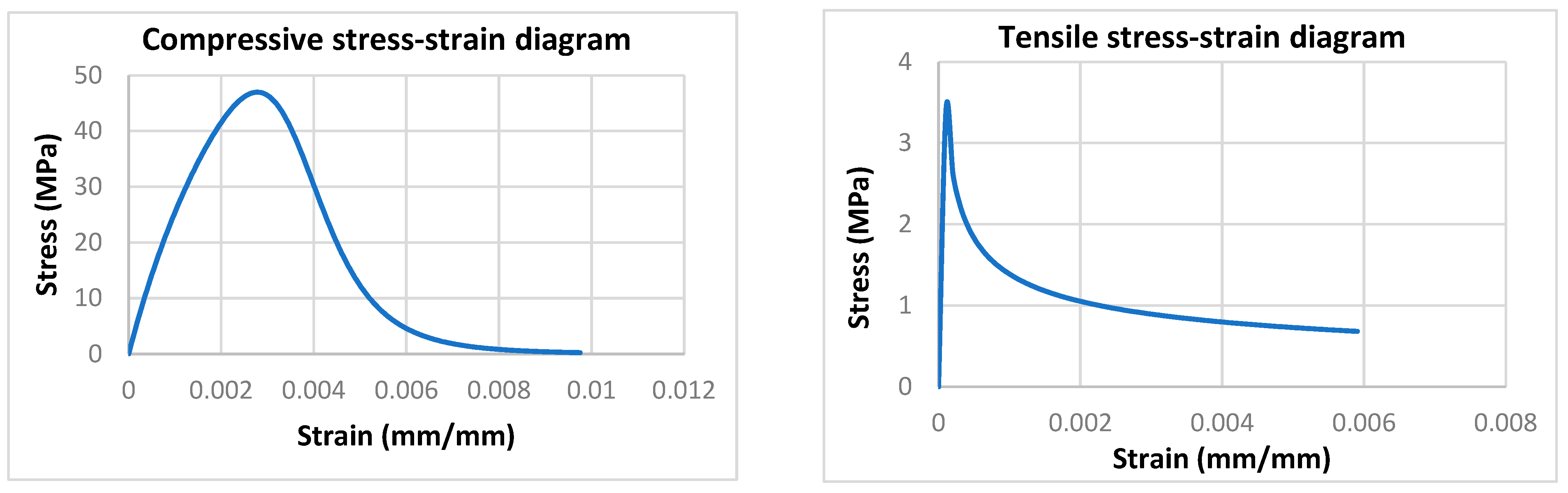
2.1.1. Concrete
2.1.2. Steel
2.1.3. Carbon Fiber Reinforced Polymer (CFRP)
2.1.4. Epoxy Resin
2.2. Beams Geometry and Reinforcement Details
2.3. Details of Specimens
2.4. Construction of Beams
2.4.1. Concrete Casting and Curing
2.4.2. CFRP Installation
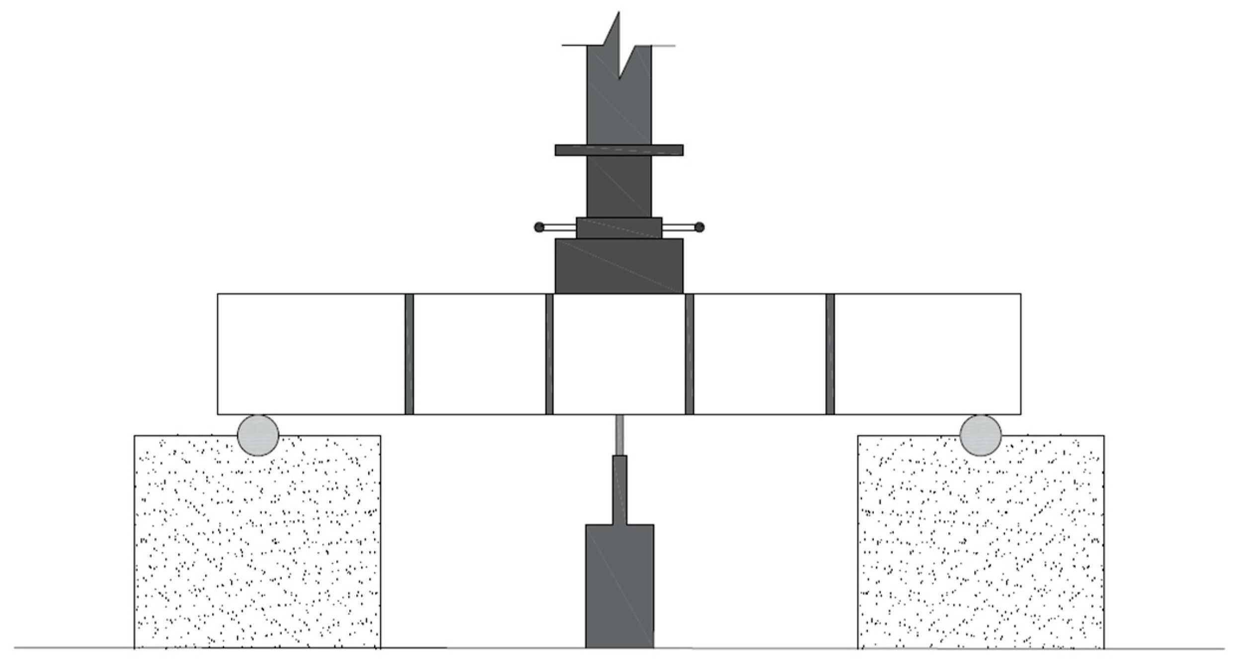
2.5. Test Setup
3. Theoretical Considerations
3.1. Theoretical Capacity According to the ACI 440.2R-17
3.2. Finite Element Analysis (FEA)
3.2.1. Parts
3.2.2. Materials Definition
3.2.3. Sections
3.2.4. Meshing
3.2.5. Interactions and Constraints
3.2.6. Boundary Conditions and Test Setup
4. Results and Discussion
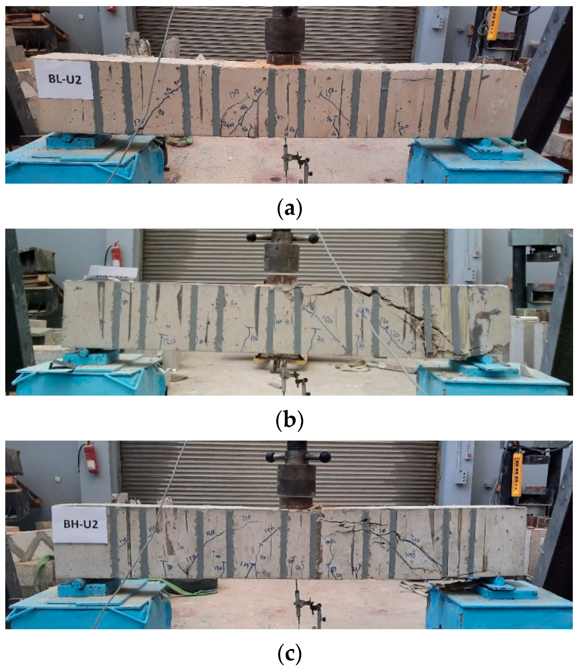
4.1. General Behavior and Failure Modes
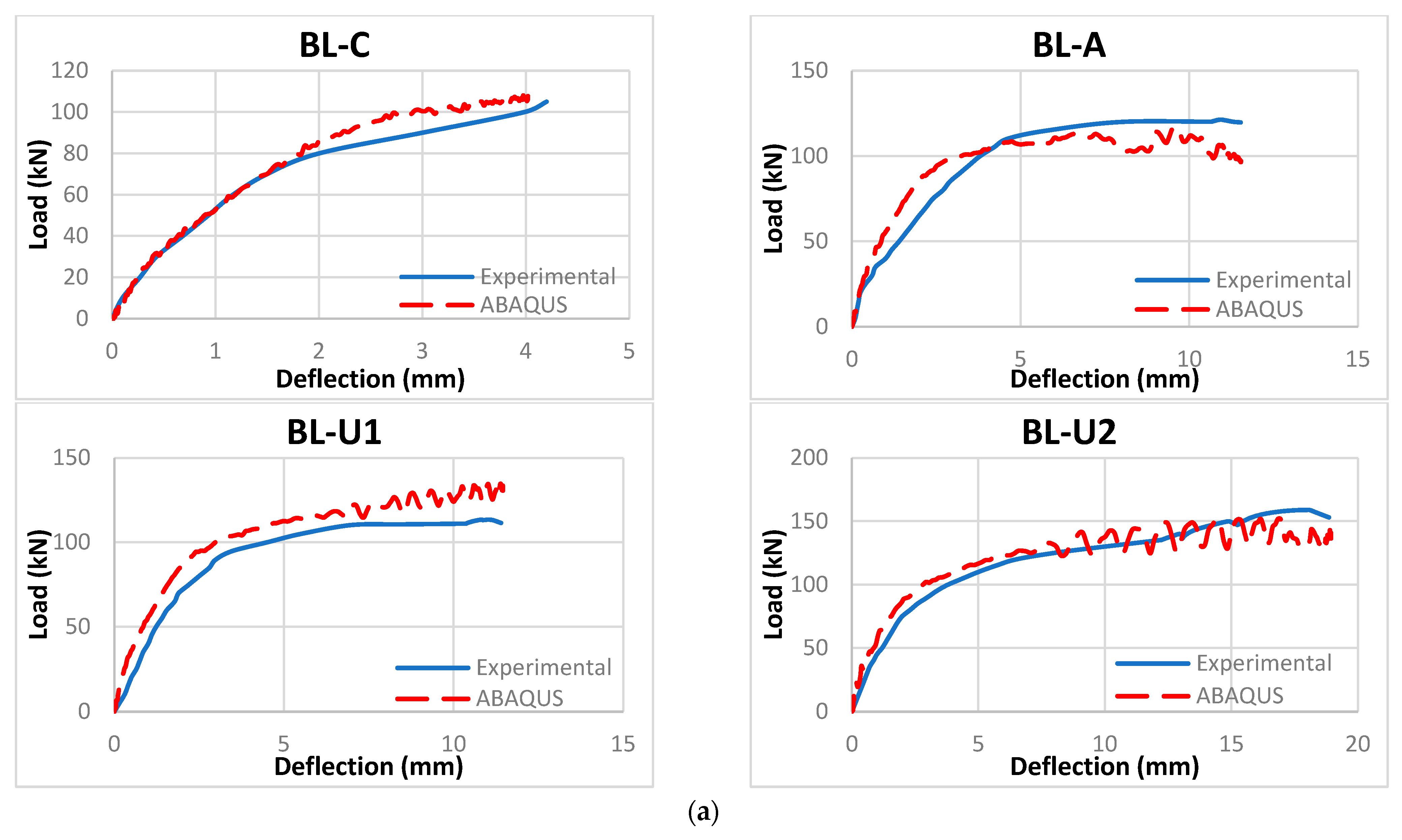
4.2. Experimental Load-Deflection Curves
4.3. Experimental Ultimate Loads
4.4. Theoretical Results
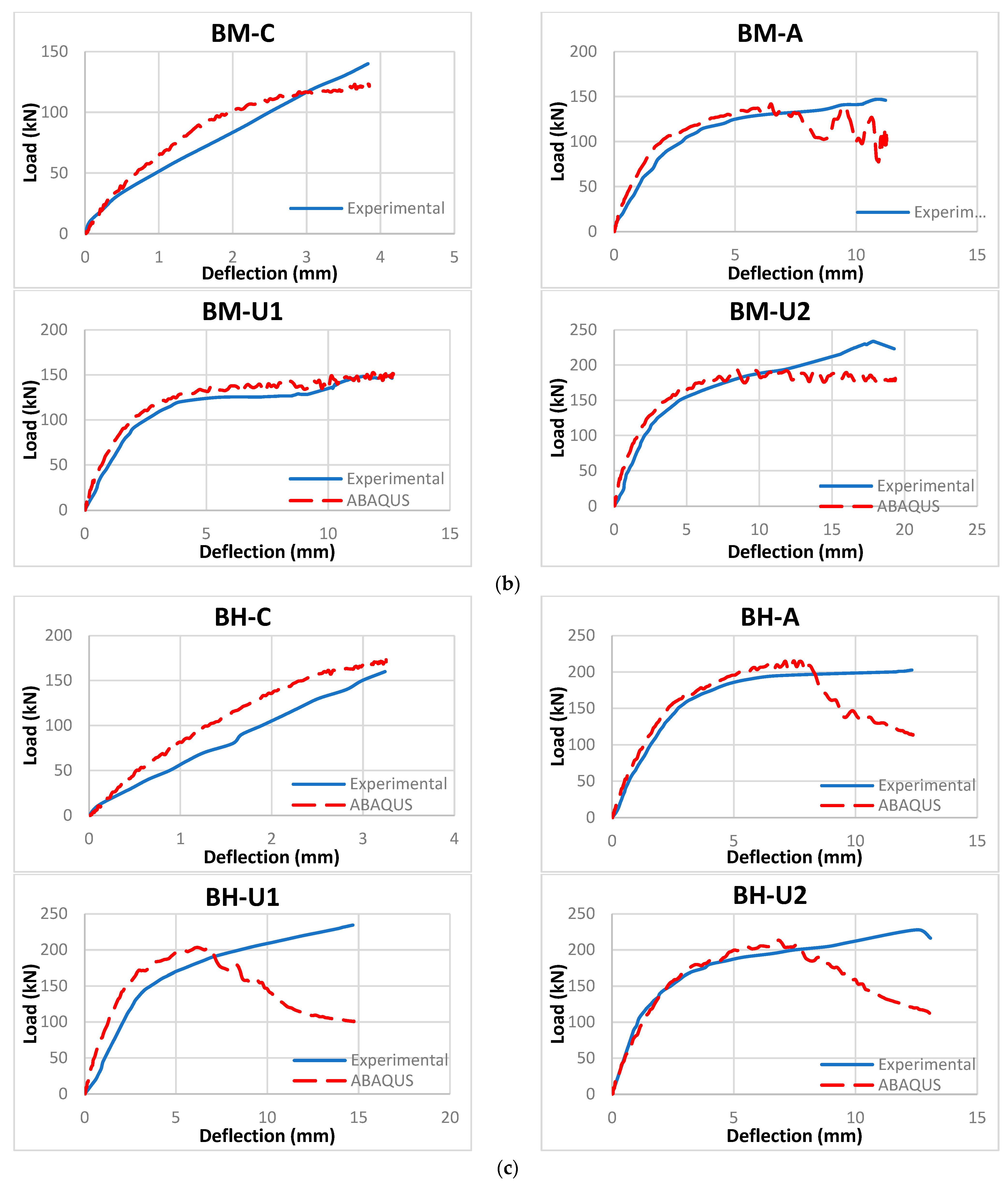
4.5. FEA Results
5. Conclusions
- The use of NSM-CFRP limited the failure modes of the beams to pure shear failure, in which no debonding or CFRP rapture was noticed during the test.
- The start, propagation, and inclination of the shear cracks depend on the NSM-CFRP scheme used. The shear cracks initiated after the first vertical NSM-CFRP strip if it was close to the support and changed its inclination between any two strips to reach the top face of the beam near the loading point.
- Experimental load-deflection curves indicated that beams with NSM-CFRP attached have higher ductility than their corresponding control beams as they recorded higher deflection values.
- In general, the experimental shear capacity increased with the increase of the compressive strength used for all beams strengthened with the same NSM-CFRP configuration.
- The experimental shear capacity of all beams strengthened with NSM-CFRP was higher than their corresponding control beams, in which the enhancement in shear capacity was in a range of 4–66%. The highest enhancement was recorded for beams with the unaligned two NSM-CFRP strips pattern, followed by the unaligned one NSM-CFRP strip pattern and then the aligned strips.
- The ACI 440.2R-17 was found to be conservative and predicted lower capacities than the experimental ones. However, the effect of the alignment between the NSM-CFRP strips and internal shear stirrups, as well as the number of unaligned NSM-CFRP strips, were not taken into consideration; thus, the theoretical values and enhancement percentages did not match the experimental results. As a result, the code equations for the shear design of NSM-CFRP should be adjusted to consider these factors to obtain more accurate capacities.
- The FEA showed acceptable results with respect to the crack patterns and maximum load capacities.
Author Contributions
Funding
Institutional Review Board Statement
Informed Consent Statement
Data Availability Statement
Conflicts of Interest
References
- Islam, A.A. Effective methods of using CFRP bars in shear strengthening of concrete girders. Eng. Struct. 2009, 31, 709–714. [Google Scholar] [CrossRef]
- Rahal, K.N.; Rumaih, H.A. Tests on reinforced concrete beams strengthened in shear using near surface mounted CFRP and steel bar. Eng. Struct. 2011, 33, 53–62. [Google Scholar] [CrossRef]
- Dias, S.J.; Barros, J.A. Shear strengthening of RC T-beams with low strength concrete using NSM CFRP laminates. Cem. Concr. Compos. 2011, 33, 334–345. [Google Scholar] [CrossRef] [Green Version]
- Jumaat, M.Z.; Shukri, A.A.; Obaydullah, M.; Huda, M.; Hosen, M.; Hoque, N. Strengthening of RC Beams Using Externally Bonded Reinforcement Combined with Near-Surface Mounted Technique. Polymers 2016, 8, 761. [Google Scholar]
- Obaidat, Y.T.; Barham, W.S.; Aljarah, A.H. New anchorage technique for NSM-CFRP flexural strengthened RC beam using steel clamped end plate. Constr. Build. Mater. 2020, 263, 120246. [Google Scholar] [CrossRef]
- Abed, D.J.; Nasim, M.S.; Shatarat, K. Behavior of Square Reinforced- Concrete Columns Strengthened with Carbon Fiber Reinforced Polymers (Cfrp) Under Eccentric Loading. Int. J. Civ. Eng. Technol. 2018, 9, 532–547. [Google Scholar]
- Dong, J.; Wang, Q.; Guan, Z. Structural Behavior of RC Beams with External Flexural and Flexural–Shear Strengthening by FRP Sheets. Compos. Part B 2013, 44, 604–612. [Google Scholar] [CrossRef]
- Al-Ghanim, H.; Al-Asi1, A.; Abdel-Jaber, M.; Alqam, M. Shear and Flexural Behavior of Reinforced Concrete Deep Beams Strengthened with CFRP Composites. Mod. Appl. Sci. 2017, 10, 110–122. [Google Scholar] [CrossRef] [Green Version]
- Hassan, S.K.; Abdel-Jaber, M.S.; Alqam, M. Rehabilitation of Reinforced Concrete Deep Beams Using Carbon Fiber Reinforced Polymers (CFRP). Mod. Appl. Sci. 2018, 12, 179–194. [Google Scholar] [CrossRef]
- Chajes, M.J.; Januska, T.F.; Mertz, D.R.; Thomson, T.A.; Finch, W.W. Shear Strengthening of Reinforced Concrete Beams Using Externally Applied Composite Fabrics. ACI Struct. J. 1995, 92, 295–303. [Google Scholar]
- Triantafillou, T.C. Shear Strengthening of Reinforced Concrete Beams Using Epoxy-Bonded FRP Composites. ACI Struct. J. 1998, 95, 107–115. [Google Scholar]
- Abdel-Jaber, M. Shear Strengthening of Reinforced Concrete Beams Using Externally Bonded Carbon Fibre Reinforced Plates. Ph.D. Thesis, Oxford Brookes University, Oxford, UK, 2001. [Google Scholar]
- Teng, J.G.; Smith, S.T.; Yao, J.; Chen, J.F. Intermediate Crack-induced De-bonding in RC Beams and Slabs. Constr. Build. Mater. 2003, 17, 447–462. [Google Scholar] [CrossRef]
- Abdel-Jaber, M.S.; Walker, P.R.; Hutchinson, A.R. Shear Strengthening of Reinforced Concrete Beams Using Different Configurations of Externally Bonded Carbon Fibre Reinforced Plates. Mater. Struct. J. 2003, 36, 291–301. [Google Scholar] [CrossRef]
- Chen, J.F.; Tengb, J.G. Shear Capacity of FRP-Strengthened RC Beams: FRP Debonding. Constr. Build. Mater. 2003, 17, 27–41. [Google Scholar] [CrossRef]
- Bousselham, A.; Chaallal, O. Shear Strengthening Reinforced Concrete Beams with Fiber-Reinforced Polymer: Assessment of Influencing Parameters and Required Research. ACI Struct. J. 2004, 101, 219–227. [Google Scholar]
- Zhang, Z.; Hsu, C.T. Shear Strengthening of Reinforced Concrete Beams Using Carbon-Fiber-Reinforced Polymer Laminates. J. Compos. Constr. 2005, 9, 158–169. [Google Scholar] [CrossRef]
- Adhikary, B.B.; Mutsuyoshi, H. Shear Strengthening of Reinforced Concrete Beams Using Various Techniques. Constr. Build. Mater. 2006, 20, 366–373. [Google Scholar] [CrossRef]
- Abdel Hafez, A. Shear Behavior of RC Beams Strengthened Externally with Bonded CFRP–U Strips. J. Eng. Sci. 2007, 35, 361–379. [Google Scholar] [CrossRef]
- Abdel-Jaber, M.S.; Shatanawi, A.S.; Abdel-Jaber, M.S. Guidelines for Shear Strengthening of Beams Using Carbon Fiber-Reinforced Polymer (FRP) Plates. Jordan J. Civ. Eng. 2007, 1, 327–335. [Google Scholar]
- Barros, J.A.; Dias, S.J.; Lima, J.L. Efficacy of CFRP-based Techniques for the Flexural and Shear Strengthening of Concrete Beams. Cem. Concr. Compos. 2007, 29, 203–217. [Google Scholar] [CrossRef]
- Al-Tersawy, S. Effect of Fiber Parameters and Concrete Strength on Shear Behavior of Strengthened RC Beams. Constr. Build. Mater. 2013, 44, 15–24. [Google Scholar] [CrossRef]
- Imran, M.; Shafiq, N.; Akbar, I. Strengthening Techniques & Failure Modes of RC Beam Strengthened Using Fibre Reinforced Polymer. A Review. GSTF J. Eng. Technol. 2013, 2, 93–98. [Google Scholar]
- Mostofinejad, D.; Hosseini, S.A.; Razavi, S.B. Influence of Different Bonding and Wrapping Techniques on Performance of Beams Strengthened in Shear Using CFRP Reinforcement. Constr. Build. Mater. 2016, 116, 310–320. [Google Scholar] [CrossRef]
- Ibrahim, A.M.; Mansor, A.A.; Hameed, M. Structural Behavior of Strengthened RC Beams in Shear using CFRP Strips. Open Civ. Eng. J. 2017, 11, 205–215. [Google Scholar] [CrossRef] [Green Version]
- Mhanna, H.H.; Hawilehb, R.A.; Abdallac, J.A. Shear Strengthening of Reinforced Concrete Beams Using CFRP Wraps. Procedia Struct. Integr. 2019, 17, 214–221. [Google Scholar] [CrossRef]
- Bukhari, I.A.; Vollum, R.L.; Ahmad, S.; Sagaseta, J. Shear Strengthening of Reinforced Concrete beams with CFRP. Mag. Concr. Res. 2010, 62, 65–77. [Google Scholar] [CrossRef] [Green Version]
- Alsayed, S.H.; Siddiqui, N.A. Reliability of Shear-Deficient RC Beams Strengthened with CFRP-Strips. Constr. Build. Mater. 2013, 42, 238–247. [Google Scholar] [CrossRef]
- Godat, A.; Qu, Z.; Lu, Z.X.; Labossiere, P.; Ye, L.P.; Neale, K.W. Size Effects for Reinforced Concrete Beams Strengthened in Shear with CFRP Strips. J. Compos. Constr. 2010, 14, 260–271. [Google Scholar] [CrossRef]
- De Lorenzis, L.; Teng, J.G. Near-Surface Mounted FRP Reinforcement: An emerging technique for strengthening structures. Compos. Part B 2007, 38, 119–143. [Google Scholar] [CrossRef]
- Sena-Cruz, J.M.; Barros, J.A.O. Bond between near-surface mounted CFRP laminate strips and concrete. J. Compos. Constr. ASCE 2004, 8, 519–527. [Google Scholar] [CrossRef] [Green Version]
- Rizzo, A.; De Lorenzis, L. Behavior and capacity of RC beams strengthened in shear with NSM FRP reinforcement. Construct. Build. Mater. 2009, 23, 1555–1567. [Google Scholar] [CrossRef]
- Rjoub, Y.S.A.; Ashteyat, A.M.; Obaidat, Y.T.; Bani, S.Y. Shear strengthening of RC beams using near-surface mounted carbon fibre-reinforced polymers. Aust. J. Struct. Eng. 2019, 20, 54–62. [Google Scholar] [CrossRef]
- Saadah, M.; Ashteyat, A.; Murad, Y. Shear strengthening of RC beams using side near surface mounted CFRP ropes and strips. Structures 2021, 32, 380–390. [Google Scholar] [CrossRef]
- ACI 440.2R-17, Guide for the Design and Construction of Externally Bonded FRP Systems for Strengthening Concrete Structures, Reported by ACI Committee 440; ACI Committee: SanBernardino, CA, USA, 2017.
- ACI 318. ‘318M–19: Building Code Requirements for Reinforced Concrete and Commentary’; ACI Committee: SanBernardino, CA, USA, 2019; p. 261.
- ABAQUS User’s Manual. 2008. Available online: http://130.149.89.49:2080/v6.14/books/usb/default.htm (accessed on 18 November 2021).
- Tsai, W.T. Uniaxial compressional stress-strain relation of concrete. J. Struct Eng. 1988, 114, 2133–2136. [Google Scholar] [CrossRef]
- Okamura, H.; Maekawa, K.; Sivasubramaniyam, S. Verification of modeling for reinforced finite element. In Finite Element Of Reinforced Concrete Structures; ASCE: Reston, VA, USA, 1985; pp. 528–543. [Google Scholar]
- Tamai, S.; Shima, H.; Izumo, J.; Okamura, H. Average stress strain relationship in post yield range of steel bar in concrete. Concr. Lib. JSCE 1988, 11, 117–129. [Google Scholar]


| Density | Glass Transition Temperature | Fiber Volume Content | E-Modulus (Mean Value) | Tensile Strength (Mean Value) | Strain at Break (Minimum Value) |
|---|---|---|---|---|---|
| 1.60 g/cm3 | >100 °C | >68% | 165,000 N/mm2 | 3100 N/mm2 | >1.70% |
| Density | Thermal Expansion Coefficient | E-Modulus (Mean Value) | Tensile Strength (Mean Value) | Bond Strength | Elongation at Break |
|---|---|---|---|---|---|
| 1.30 kg/L ± 0.1 kg/L (part A + B mixed) | 4.5 × 10⁻⁵ per °C (−10 °C to +40 °C) | 3800 N/mm2 (7 days at +23 °C) | 30 N/mm2 (7 days at +23 °C) | Concrete fracture (>4 N/mm2) on sandblasted substrate | 0.9% (7 days at +23 °C) |
| 4500 N/mm2 (7 days at +23 °C) |
| Sample | Experimental Load (kN) | Percent Increase (%) | |
|---|---|---|---|
| Low Strength Concrete | BL | 105.0 | - |
| BL-A | 121.3 | 16% | |
| BL-U1 | 113.4 | 8% | |
| BL-U2 | 158.9 | 51% | |
| Medium Strength Concrete | BM | 141.0 | - |
| BM-A | 147.0 | 4% | |
| BM-U1 | 149.4 | 6% | |
| BM-U2 | 233.8 | 66% | |
| High Strength Concrete | BH | 168.4 | - |
| BH-A | 202.8 | 20% | |
| BH-U1 | 234.5 | 39% | |
| BH-U2 | 228.7 | 36% | |
| Sample | Experimental Shear Load (kN) | Theoretical Load (kN) | Percent Increase (%) | |
|---|---|---|---|---|
| Low Strength Concrete | BL | 52.5 | 40.3 | 23.2 |
| BL-A | 60.6 | 42.5 | 29.9 | |
| BL-U1 | 56.7 | 42.5 | 25.0 | |
| BL-U2 | 79.5 | 43.3 | 45.5 | |
| Medium Strength Concrete | BM | 70.5 | 52.6 | 25.5 |
| BM-A | 73.5 | 56.1 | 23.7 | |
| BM-U1 | 74.7 | 56.1 | 24.9 | |
| BM-U2 | 116.9 | 57.3 | 50.9 | |
| High Strength Concrete | BH | 84.2 | 58.5 | 30.5 |
| BH-A | 101.4 | 62.8 | 38.0 | |
| BH-U1 | 117.2 | 62.8 | 46.4 | |
| BH-U2 | 114.3 | 64.4 | 43.7 | |
Publisher’s Note: MDPI stays neutral with regard to jurisdictional claims in published maps and institutional affiliations. |
© 2021 by the authors. Licensee MDPI, Basel, Switzerland. This article is an open access article distributed under the terms and conditions of the Creative Commons Attribution (CC BY) license (https://creativecommons.org/licenses/by/4.0/).
Share and Cite
Abdel-Jaber, M.; Abdel-Jaber, M.; Katkhuda, H.; Shatarat, N.; El-Nimri, R. Influence of Compressive Strength of Concrete on Shear Strengthening of Reinforced Concrete Beams with Near Surface Mounted Carbon Fiber-Reinforced Polymer. Buildings 2021, 11, 563. https://doi.org/10.3390/buildings11110563
Abdel-Jaber M, Abdel-Jaber M, Katkhuda H, Shatarat N, El-Nimri R. Influence of Compressive Strength of Concrete on Shear Strengthening of Reinforced Concrete Beams with Near Surface Mounted Carbon Fiber-Reinforced Polymer. Buildings. 2021; 11(11):563. https://doi.org/10.3390/buildings11110563
Chicago/Turabian StyleAbdel-Jaber, Ma’en, Mu’tasim Abdel-Jaber, Hasan Katkhuda, Nasim Shatarat, and Rola El-Nimri. 2021. "Influence of Compressive Strength of Concrete on Shear Strengthening of Reinforced Concrete Beams with Near Surface Mounted Carbon Fiber-Reinforced Polymer" Buildings 11, no. 11: 563. https://doi.org/10.3390/buildings11110563