Article

Filtration Performance of Ultrathin Electrospun Cellulose Acetate Filters Doped with TiO2 and Activated Charcoal

1
Department of the Built Environment, Aalborg University, DK-2450 Copenhagen, Denmark
2
Department of Building Science, Tsinghua University, Beijing 100084, China
3
Beijing Key Laboratory of Indoor Air Quality Evaluation and Control, Beijing 100084, China
4
Department of Materials and Production, Aalborg University, DK-9220 Aalborg, Denmark
*
Author to whom correspondence should be addressed.
Buildings 2021, 11(11), 557; https://doi.org/10.3390/buildings11110557
Submission received: 4 November 2021 / Revised: 16 November 2021 / Accepted: 17 November 2021 / Published: 18 November 2021
(This article belongs to the Section Building Energy, Physics, Environment, and Systems)

Abstract

:
Air filters are crucial components of a building ventilation system that contribute to improving indoor air quality, but they are typically associated with relatively high pressure drops. The purpose of the study is to evaluate the effect of additives on ultrathin electrospun filters, the pressure drop, and the particle removal efficiency of uniformly charged particles. The fibres were electrospun under optimised conditions that resulted in a fast-fabricating process due to the properties of the cellulose acetate solution. Different ultrathin electrospun fibre filters based on cellulose acetate (CA) were fabricated: a pure CA electrospun fibre filter, two filters based on CA fibres separately doped with activated charcoal (AC) and titanium dioxide (TiO2), respectively, and a composite filter where the two additives, AC and TiO2, were embedded between two CA fibres layers. The ultrathin filters exhibited a low pressure drop of between 63.0 and 63.8 Pa at a face velocity of 0.8 m s−1. The filtration performance of uniformly charged particles showed a removal efficiency above 70% for particle sizes between 0.3 and 0.5 μm for all filters, rising above 90% for larger particles between 1 and 10 μm, which translates to the average sizes of pollens and other allergenic contaminant particles. Due to the positive impact on the fibre morphology caused by the additives, the composite filter showed the highest filtration performance among the produced filters, reaching 82.3% removal efficiency towards smaller particles and a removal of up to 100% for particle sizes between 5 and 10 μm. Furthermore, cellulose acetate itself is not a source of microparticles and is fully biodegradable compared to other polymers commonly used for filters. These ultrathin electrospun filters are expected to be practical in applications for better building environments.

1. Introduction

Exposure to particle pollution has been linked to negative health effects such as cardiovascular and respiratory disorders and lung cancer, and it can lead to increased mortality [1,2,3,4]. Although the World Health Organization (WHO) has defined clear guidelines for annual average outdoor concentration as 5 µg m−3 for PM2.5 (particulate matter with an aerodynamic diameter less than 2.5 µm) and 15 µg m−3 for PM10 (particulate matter with an aerodynamic diameter less than 10 µm) [5], 91% of the world population lives in areas where these guidelines are not met. Particles originating outdoors can enter residential and non-residential buildings and negatively affect indoor air quality [6,7].
As a significant portion of indoor particles originates outdoors, supply air filters can prevent the outdoor-to-indoor transport of particle pollution and improve indoor air quality. Several air filter technologies can be used to remove particles [8,9,10]. Commercial fibrous filters, such as HEPA filters, can remove up to 99.97% of particles with diameters larger than 0.3 μm [11] at the expense of a relatively large pressure drop that can negatively affect the total HVAC energy use [12]. Typically, electrostatic filters achieve lower particle filtration efficiency compared to mechanical filters with the advantage of a much lower air resistance [13]. Most conventional filters require the use of a fan to overcome the pressure drop they impose on the air stream, and therefore, they contribute to an increased energy use from the ventilation system [14]. Air filter contribution can account for between 20 and 50% of the total pressure drop of a ventilation system depending on the loading conditions, filter efficiency, and system configuration [15]. This has a direct impact on the energy use of the ventilation fans, which can account for up to 34% of the total energy use of the HVAC system [14]. The main challenge that air filtration technologies have to overcome today is to optimise the ratio between filtration efficiency and energy use during operation, therefore achieving the highest dust-loading capacity with the lowest air resistance possible. Recent studies have focused on fibre filters produced with electrospinning as a potential solution to overcoming this challenge.
Electrospinning is a versatile and effective method of producing fibres with diameters within the nano- or submicron dimension, which are characterised by various morphologies and properties [16]. When the fibre diameter is reduced to nanoscale, which is comparable to or smaller than the mean free path of air molecules (65 nm), lower air resistance of the filters will occur by introducing a slip effect [17,18]. Thus, electrospun fibre filters aiming at a decreased pressure drop have been fabricated in numerous research studies in recent years [19,20]. A polyacrylonitrile (PAN)-based electrospun nanofibre membrane with a fibre diameter in the range of 50–170 nm was fabricated [17]. The electrospinning process was optimised, and a particle filtration efficiency of 99.09% was obtained, while the pressure drop reached 29 Pa with a face velocity of 0.053 m s−1 [17]. A silk fibroin/polyvinyl alcohol (SF/PVA) nanofibre air filter was developed aiming at efficient particle capture [21]. The filter reached 99.11% removal efficiency and a pressure drop of 50 Pa at 0.5 m s−1 air velocity [21]. Moreover, a method to fabricate an electrospun nanofibre filter to minimise the pressure drop when removing particles below 2.5 µm was developed [22]. An optimised approach based on a semi-empirical model was applied on 125 samples, which obtained a decreased pressure drop for 110 cases. The optimal nylon-based filter has achieved 90% filtration efficiency at the cost of 27.18 Pa at a face velocity of 0.05 m s−1 [22]. Composite electrospun fibre mats have been recently fabricated [23,24]. A polyimide-based electrospun membrane with metal–organic frameworks (MOFs) successfully removed VOCs such as polar formaldehyde (sorption capacity 124 mg g−1) and non-polar toluene (142 mg g−1), xylene (214 mg g−1), and mesitylene (201 mg g−1) from air [23]. A polymeric composite electrospun nanofibre mat was produced to remove air particles and to investigate the antibacterial activity enhanced by the sulfobetaine zwitterionic groups. The materials achieved 99.9% removal of Klebsiella pneumoniae and Staphylococcus aureus bacteria and exhibited high filtration efficiency (>99.9%) with a pressure drop of 177 Pa at 5.3 cm s−1 face velocity [24].
The fibre morphology has to be tuned properly in order to achieve an optimal ratio between particle removal and pressure drop. The typical face velocities used in an HVAC system can reach up to 2 m s−1, but nanofibre filters are generally tested at much lower face velocities (0.05 m s−1) [25]. The effect of additives on the morphological filter parameters such as porosity, fibre diameter, and fibre surface roughness has also been a subject of focus [16]. The addition of titanium dioxide was shown to improve the particle filtration efficiency of polymer-based electrospun nanofibre filters [26]. The PSU/TiO2 membrane has an enhanced filtration efficiency of 99.997% for 0.3–0.5 µm particles and a pressure drop of 43.5 Pa at a face velocity of 0.05 m s−1 compared to the pristine PSU filter due to the enhanced porous structure and surface fractal features with irregular rough structures [26]. The combined use of titanium dioxide and activated charcoal when fabricating nanofibres could contribute to the formation of macroporous structures that can decrease the pressure drop [27]. Activated charcoal and titanium dioxide are often used as additives on fibre filters for their properties as an adsorbent and photocatalyst to enhance the removal capacity of the filters towards gaseous pollutants [28,29], although their influence on particle filtration efficiency has not been widely investigated.
Other researchers have used continuous electrostatic effects on traditional air filters to apply a uniform charge to particles and evaluate the filtration efficiency [30,31,32]. The particle filtration efficiencies for two commercial HVAC filters have been improved from 5⁠–15% to 40–⁠90% by utilising continuous emission of unipolar ions without affecting the pressure drop [32]. A compact electrostatically assisted air (EAA) filter, which combines corona charging and filter polarising, was developed [33]. The single-pass efficiency for 0.3–⁠0.5 µm charged particles of a polyethylene terephthalate (PET) coarse filter was improved from 0.4% to 99%. The air resistance of the filter led to a pressure drop of 21 Pa at 1.2 m s−1 face velocity [33]. Furthermore, the efficiency for the PET coarse filter could be significantly improved by a thin coating of polydopamine (PDA) via in situ dopamine polymerisation. Using a two-stage EAA filtration device, the PDA@PET filter has a high filtration efficiency of 99.48% for 0.3 µm particles, low air resistance of 9.5 Pa at a filtration velocity of 0.4 m s−1, and steady performance for up to 30 days [34]. An electrostatically assisted metal foam and PVDF electrospun nanofibres were combined to enhance filtration efficiency by 15% for charged particles with an aerodynamic diameter between 0.3 and 0.5 µm [35]. Moreover, an electrically responsive polyurethane filter with dielectric surface coatings could even achieve 90.50% removal efficiency for ultrafine particles and an ultralow pressure drop at 13.0 Pa at 1 m s−1 face velocity, providing a promising prospect when applied in building ventilation systems [36].
The present study introduces four different ultrathin electrospun fibre filters. These filters exhibit a thickness between 0.1 and 0.2 mm, whereas conventional and commercial filters usually present a thickness ranging from a few to tens of centimetres. The selected polymer was cellulose acetate (CA), which is an abundant and biodegradable organic compound commonly used for application in filters, artificial skin, and protective clothing [37,38]. Employing CA instead of commonly used polymers is beneficial because CA is not a source of microplastic, and it does not increase the plastic load when disposed of, as it is biodegradable. Electrospinning of this polymer has been systematically investigated, reaching fast and stable results [39].
The purpose of this study was to evaluate experimentally the influence of additives such as titanium dioxide and activated charcoal on the filtration performance of uniformly charged particles for CA-based ultrathin electrospun fibre filters. Furthermore, the impact on the performance as measured by filtration efficiency and pressure drop of the different ultrathin filter matrices was also assessed. Compared to the reported electrospun filters in the literature, the novelty of the filters presented here is related to their high porosity and low pressure drop but still maintaining a good filtration efficiency, which is evident from the quality factor. This paper presents the fabrication process via electrospinning of the different fibre filters, which differs in terms of materials and filter configuration. The results from the experimental study of the filtration performance are described and discussed, including the achieved pressure drop and the particle filtration efficiency. The filters were also evaluated and compared in terms of filter quality factors.

2. Materials and Methods

2.1. Materials

Cellulose acetate (CA, 39.8 wt % acetyl content, MN 30000 GPC) and activated charcoal (AC, MW 12.01 g mol−1) in a powder form were purchased from Sigma-Aldrich. Aeroxide TiO2 P25 in a nanopowder form was a gift from Evonik Industries. Pure acetone, ethanol absolute, and 2-propanol were acquired by Avantor and were used as is. The materials were used without further purification.

2.2. Fabrication of Electrospun Fibre Filters

2.2.1. Preparation of CA Solution

The polymer solution was prepared by adding 31.25 g of CA to 250 mL of acetone under vigorous stirring for 12 h to obtain a homogeneous solution. The stirring was carried out at room temperature (20 °C).

2.2.2. Preparation of TiO2 and AC Dispersions

First, 1.5 g of TiO2 was dispersed in a solution of 80 mL 2-propanol and 20 mL ethanol. The mixture was vigorously stirred for an hour, and then, it was ultrasonicated in a bath for 30 min to ensure uniformity. Similarly, 2 g of AC were dispersed in a solution of 80 mL 2-propanol and 20 mL ethanol. The solution was continuously stirred to ensure a homogenous AC distribution.

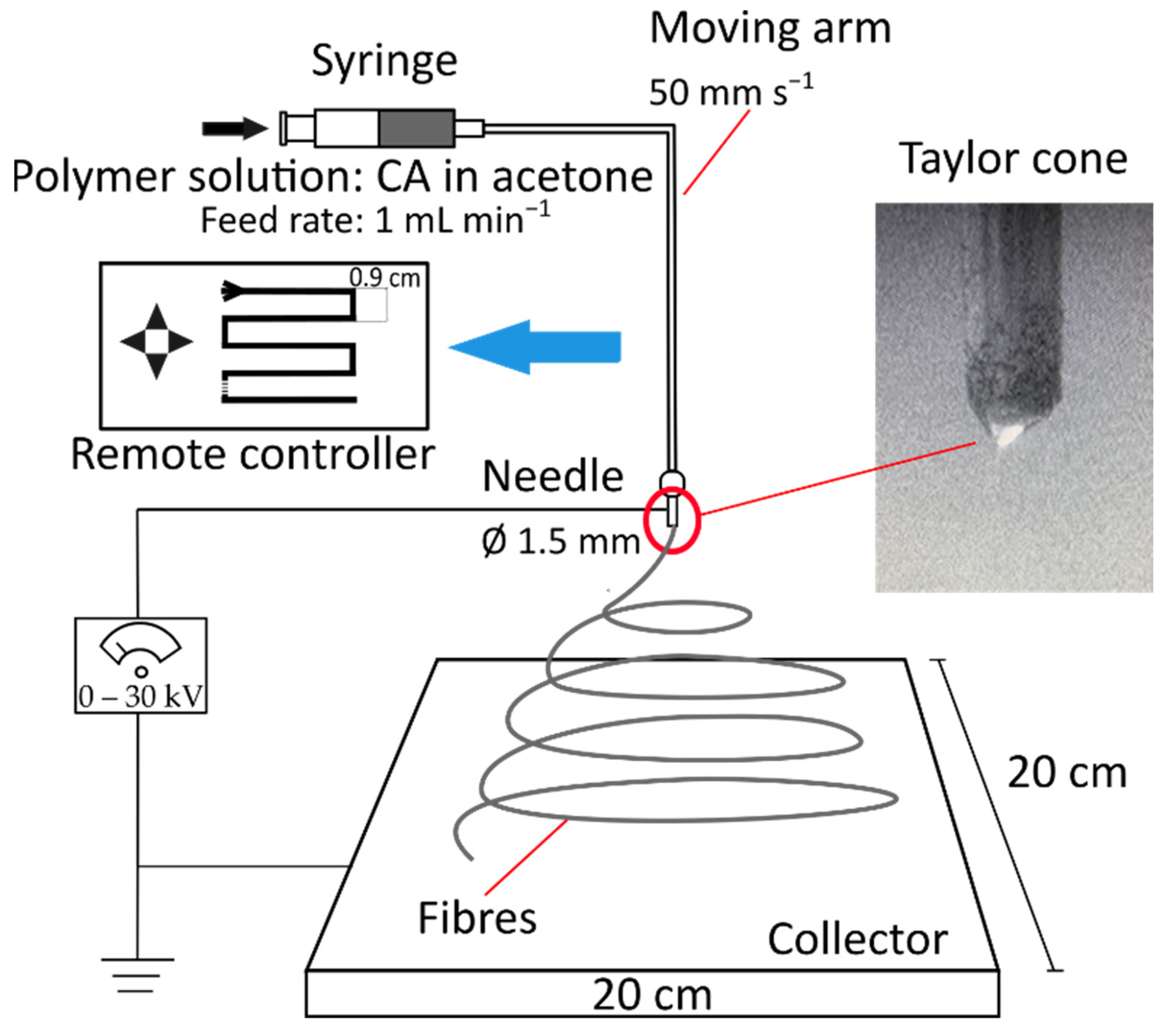
2.2.3. Electrospinning Process

The electrospinning was carried out using an electrospinner from Yflow (2.2.D-500), which is equipped with a flat collector and a remote-controlled arm where the needle is located. A schematic representation of the setup is shown in Figure 1. The electrospinning was performed in a vertical downwards configuration. For the preparation of CA electrospun fibre, the CA solution was loaded in a 20 mL glass syringe (Poulten & Graf GmbH). The solution was fed at a constant rate of 1 mL min−1 through a needle with an inner diameter of 1.5 mm. The electrospinning was continuous until 10 mL of the CA solution had been electrospun onto the collector. The voltage applied was 14.8 kV. The tip of the needle was kept at 9 cm distance from the collector. Inside the electrospinner box, the temperature ranged between 19.8 and 20.8 °C, and the relative humidity was kept between 27% and 32%. The needle was remotely controlled at a velocity of 50 mm s−1 on the collector (20 cm × 20 cm), as shown in Figure 1, to ensure the uniformity of fibre distribution across the filter surface. After electrospinning, the filter was kept in a ventilated oven at 70 °C for 1 h to ensure complete evaporation of the solvent.

2.2.4. Preparation of the Doped Filters

The CA/AC and CA/TiO2 fibre filters were prepared by spraying the additive dispersion onto the electrospun fibre filter surface using an airbrush. Such a doping method implies that the additives are deposited on the filter, modifying the first layers of the filter surface. The previously electrospun CA membrane was placed in a fume hood onto a metal grid at a distance of 20 cm from the air brush. The filter was sprayed with the respective suspension for 2 min. Then, the filter was dried in the oven at 70 °C for an hour. The airbrush process was repeated twice for each filter.
For the composite filter, the two additive dispersions were separately sprayed between two layers of CA electrospun fibre. The first layer of polymer fibre was made by electrospinning 6 mL of CA solution onto the collector. After drying the membrane for 1 h at 70 °C in the oven, two 2-min rounds of airbrushing of AC dispersion at 10 L min−1 were applied, which was interspersed with 1 h drying at 70 °C between each application. The third layer of the composite filter consisted of electrospinning 4 mL of CA solution. The fourth and final layer comprised two rounds of airbrushing of the TiO2 dispersion using the previously described conditions, including 1 h of drying at 70 °C between airbrushing applications.

2.3. Fibre Characterisation

The fibre surface morphology was investigated using scanning electron microscopy (SEM; Zeiss XB1540) operating at 5 kV. The samples were coated with a thin layer of gold before scanning. The average fibre diameter and surface porosity were measured using the DiameterJ plugin for ImageJ (1.51w, NIH, Bethesda, MD, USA) on the SEM images.
The thickness of the filters has been measured with a traditional External Micrometer (Model 965M, Moore & Wright Ltd., Sheffield, UK) with an accuracy of ±0.005 mm. The filters were folded in two and kept between two metal plates during the measurement to avoid compression of the materials.

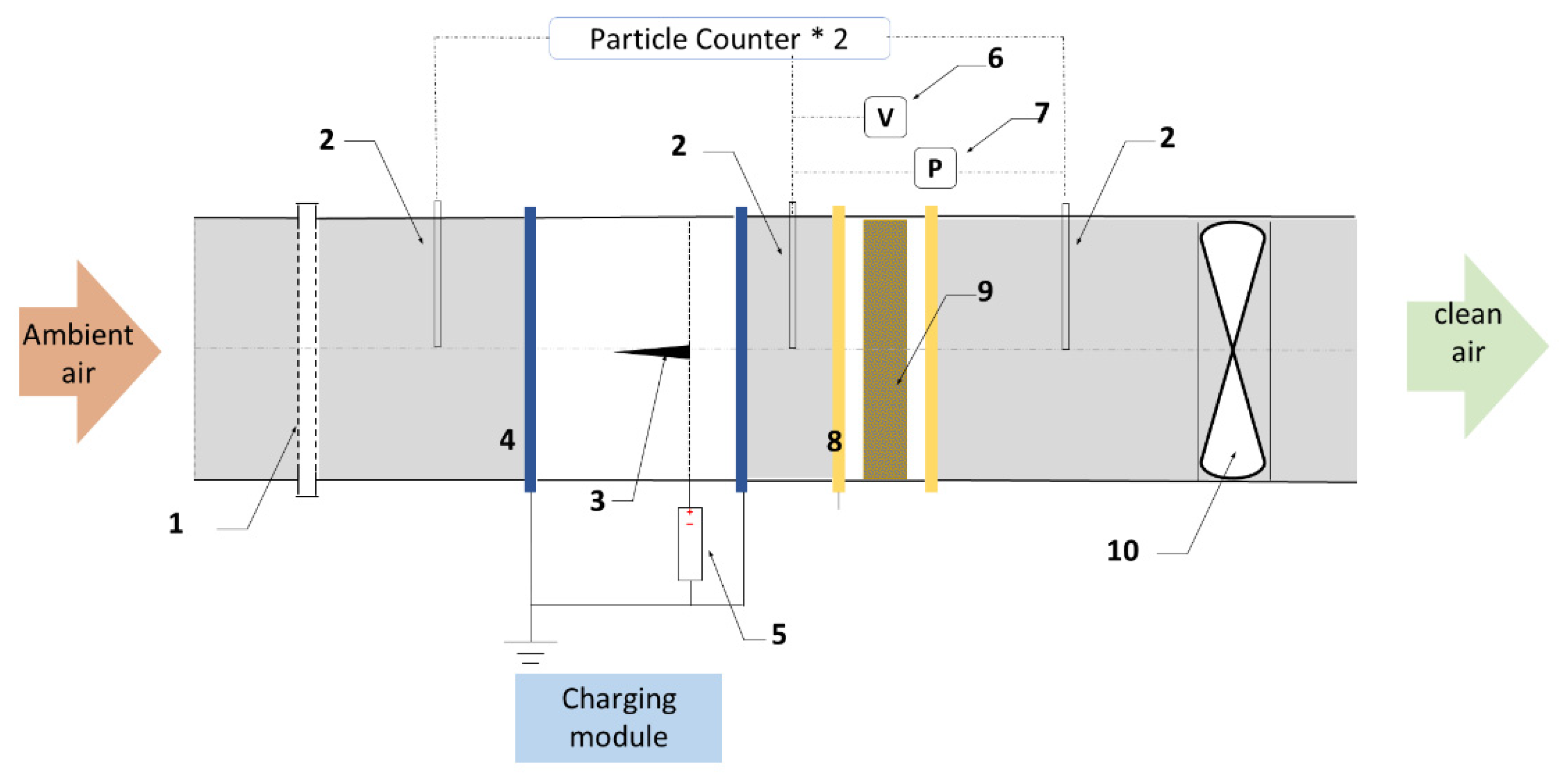
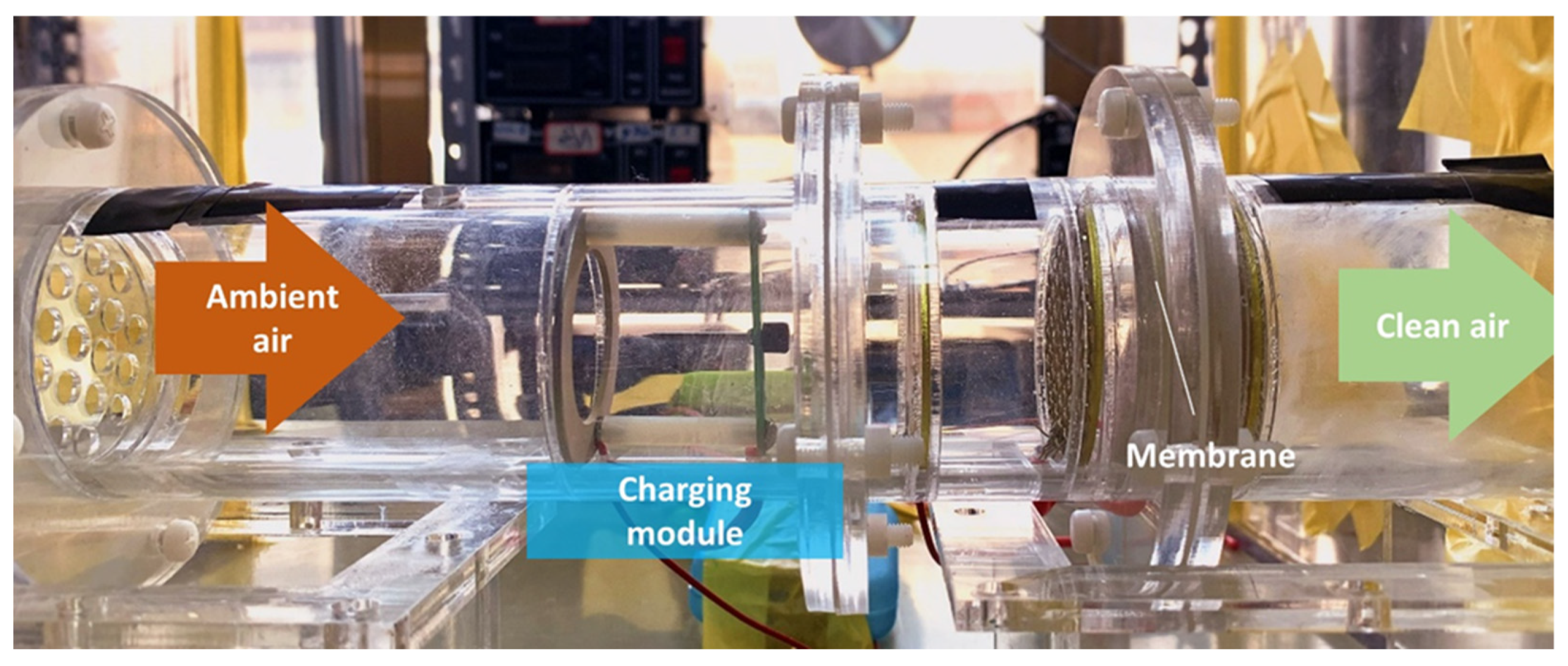
2.4. Investigation of Filtration Performance

The filtration performance tests were conducted in an acrylic air duct with an inner diameter of 50 mm, as shown in Figure 2. The filtration module is divided into the charging section and collecting section, where the membrane is kept, as shown in Figure 3. The air with ambient airborne particles was driven through the module in the sequence of a diffusion plate, a pin-to-plate charging module for the ionisation of particles, the filter to be tested, and an axial flow fan. The length of the charging pin is 20 mm, and the pin-to-plate distance is 10 mm. The charging pin was connected to an adjustable High-Voltage Direct Current (HVDC) power supply (from 0 to +30 kV, accuracy: 0.1 kV, P30, GENVOLT Co. Ltd., Beijing, China). The back metal ring of the charging module was connected to the ground. The face filtration velocity could be altered by adjusting the frequency of the fan.
The face velocity was measured by a thermo-anemometer (435-1, Testo SE & Co. KGaA, Titisee-Neustadt, Germany) located upstream of the air duct, and it was controlled at 0.8 m s−1 during the particle removal efficiency test. The number concentration of 0.3–10 µm particles was measured by a particle counter (Aerotrak 9306, TSI Inc., Shoreview, MN, USA) located upstream and downstream of the filters. A sensor (WSZY-1, Tianjianhuayi Tech. Co. Ltd., Beijing, China) was used to monitor the air temperature and relative humidity during testing in the air duct. The pressure drop across the filter was measured using a differential gauge (accuracy: ±1%, DP-CALC 5825, TSI Inc., Shoreview, MN, USA). The pressure drop was measured at several face velocities in the range between 0.035 and 1 m s−1.
Each filter was exposed to the polluted air stream for 30 min, and in this period of time, the particle concentration was monitored upstream and downstream the filter. The filtration efficiency η for charged particles based on particle size was calculated using the following equation:
η ( d p ) = ( C u p ( d p ) C d o w n ( d p ) C u p ( d p ) ) × 100   % ,
where Cup and Cdown are the particles number concentration upstream and downstream the filter respectively, and dp is the particle diameter.
The filters were also evaluated in terms of quality factor QF (Pa−1), which was calculated using the equation below.
Q F = ln ( 1 η ( 0.3 0.5   μ m ) ) Δ P ,
where η(0.3–0.5 μm) represents the single-pass filtration efficiency for particles sized between 0.3 and 0.5 µm at 0.8 m s−1 face velocity, and ∆P is the pressure drop at the same face velocity. The quality factor gives a clear understanding of which filter best optimises the ratio between pressure drop and filtration efficiency, and therefore, the ratio between the energy use related to filter operation and the filter’s contribution to an improved indoor air quality. The quality factor was calculated based on the filtration efficiency of particles with diameters between 0.3 and 0.5 µm, as this is commonly considered the most penetrating particle size.

3. Results and Discussion

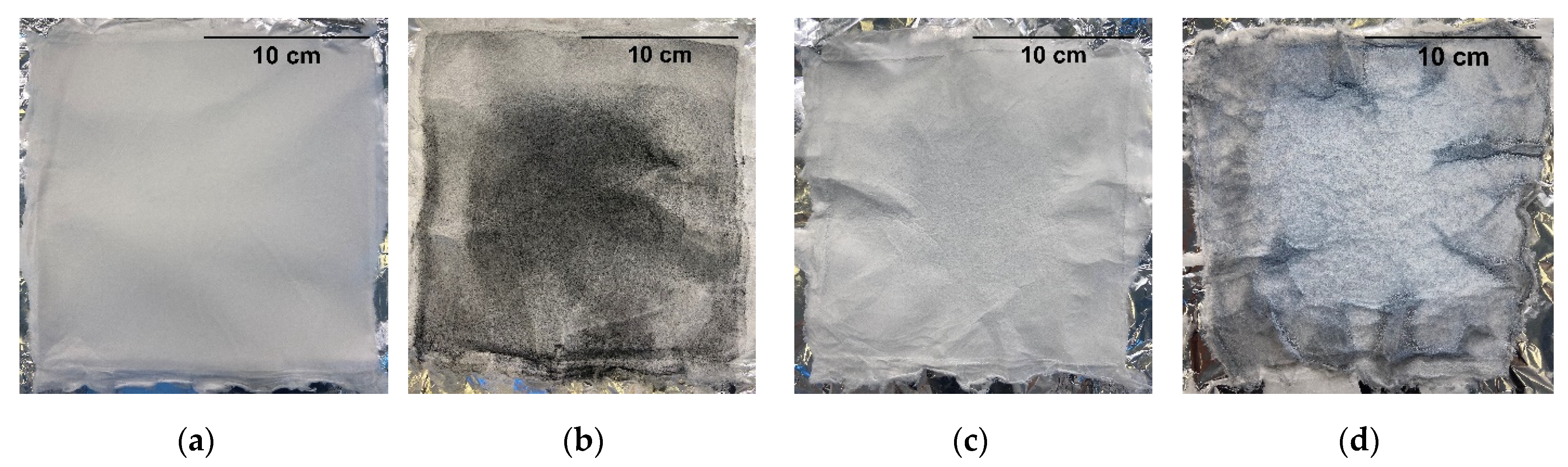
3.1. Preparation of Electrospun Fibre Filters

The characteristic parameters that define the electrospinning process of the cellulose acetate solution were adjusted from the optimal conditions mentioned in the study from Christoforou and Doumanidis [39], and these are presented in Table 1. The conditions that stabilised the electrospinning process were based on a high feed rate of 1 mL min−1. Compared to other studies, where the feed rates for the polymer solution are in the range of mL h−1 [40,41,42], the CA/acetone solution allowed for the fast fabrication of a free-from-beading and uniform fibre filter, owing also to the remotely controlled arm of the electrospinner. The final filter material is visible in Figure 4a. The air spraying of the solutions containing either AC or TiO2 resulted in the final materials visible in Figure 4b,c, respectively, while the composite material is shown in Figure 4d.

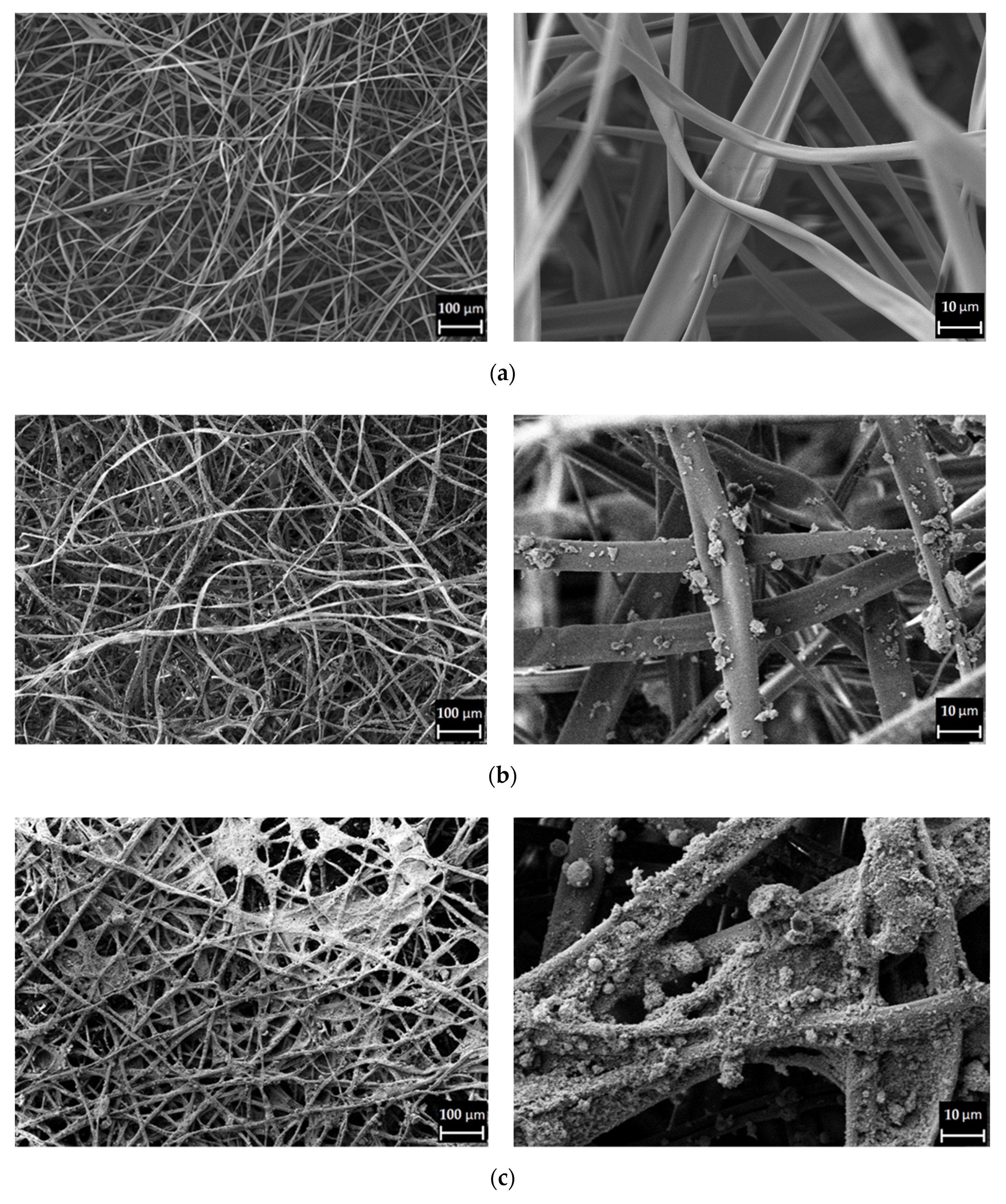
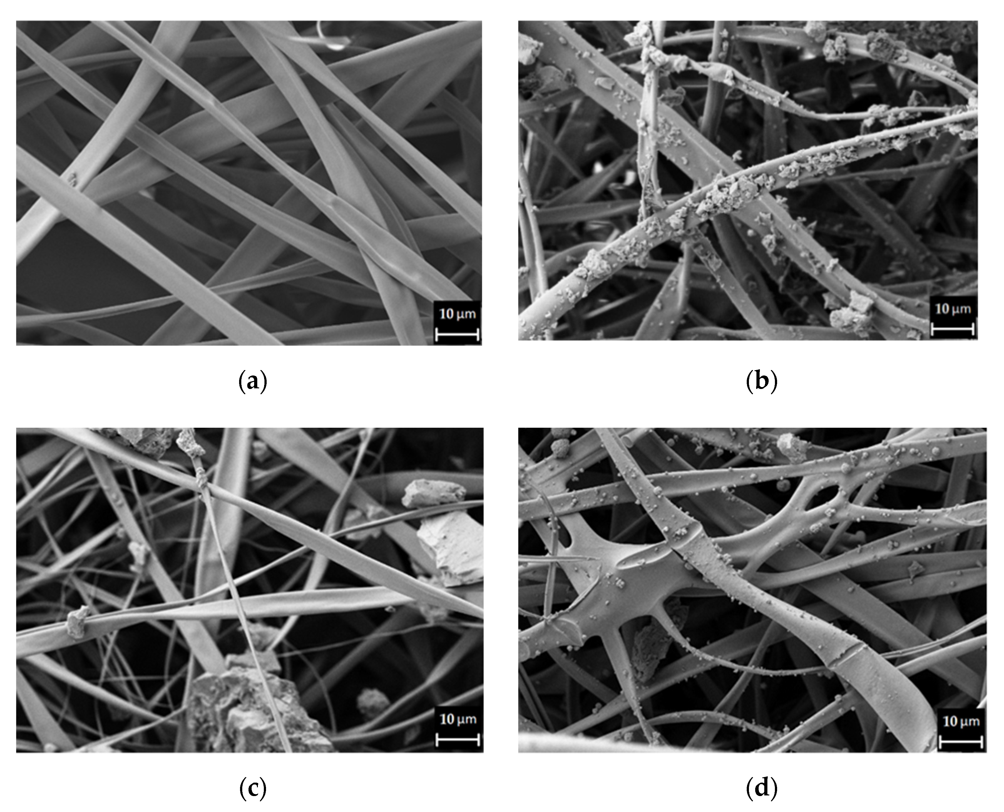
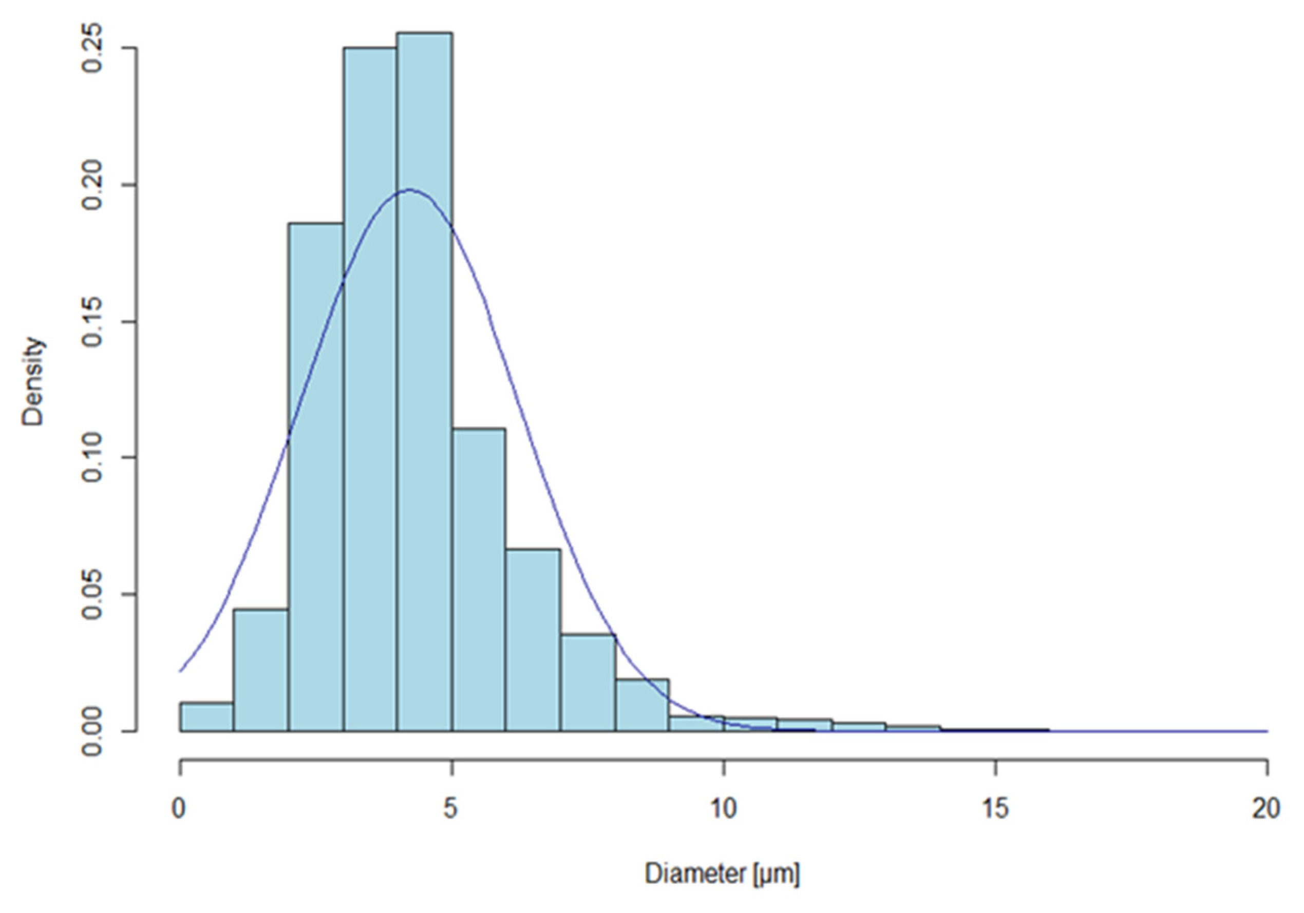
3.2. Fibre Characterisation

SEM images of different CA fibre filter samples are shown in Figure 5. The pure CA fibre presents a uniform flat-ribbon morphology, which is randomly oriented (Figure 5a). Compared to the smooth fibres of the pure CA membrane, the doped filters show a different fibre surface due to the use of additives. The CA fibre surface is visibly covered by AC (Figure 5b) and TiO2 (Figure 5c). The dense deposition of TiO2 highly affects the fibres’ morphology and the pore dimension, as the TiO2 nanoparticles are forming agglomerates which tend to increase the fibre diameter and clog the pores. The presence of activated charcoal has a milder influence on the fibre morphology. The additive is still clearly visible on the fibre surface, but it does not fully coat it, as does TiO2.
The composite filter is a combination of the previous two CA/TiO2 and CA/AC filters. SEM images of the four steps to fabricate each layer of the filters are shown in Figure 6. The presence of additives is clearly visible on the fibre surface on the second and fourth layers in the form of agglomerates.
The SEM images of the pure CA fibres have been analysed to investigate the average fibre diameter. The average diameter distribution is presented in Figure 7. The mean fibre diameter is 4.2 µm. The fibres are not falling into the nano-dimension. This is the result of the electrospinning process, which was stable at a rather fast feed rate of 1 mL min−1 and a short tip to collector distance of 9 cm. The polymer solution jet did not stretch enough to form nanofibres.
Furthermore, the surface porosity of the filters has also been determined for each filter material using ImageJ. Such a parameter is used as a comparative term for the use of the additives on the filter surface. The results are shown in Table 2. As previously mentioned, the use of additives reduces the surface porosity of the materials. The pure CA reached the highest surface porosity of 42%, while the surface porosity of CA/TiO2 dropped to the lowest value of 32.5%.
The results of the thickness analysis are also presented in Table 2. The filter thickness ranges between 0.11 and 0.18 mm, and the results are consistent with the use of additives. The pure CA filter is the thinnest filter, whereas the composite filter, which incorporates two layers of additives, is the thickest material among the four samples.

3.3. Filtration Performance

The filter materials previously presented were cut into filters to install them into the set up (inner diameter: 50 mm) designed to evaluate the pressure drop and filtration efficiency.

3.3.1. Pressure Drop

The filters’ pressure drop was investigated in two different ranges of face velocity. Electrospun fibre filters are mostly tested at face velocity in the range from 10−2 to 10−1 m s−1; many of those are between 0.2 and 0.053 m s−1 [25]. The filters developed were also evaluated in the low range of face velocity starting from 0.035 m s−1 up to 0.087 m s−1, which would reproduce the case of a filter installed under natural ventilation conditions. However, such filters could be used in buildings as part of a mechanically ventilated system, where face velocities are as high as 1 m s−1. Therefore, the filters were also tested at 0.8 m s−1 and 1 m s−1. The results are shown in Table 3.
The pure CA fibre filter showed a starting pressure drop of 3.5 Pa at a face velocity of 0.053 m s−1. The use of additives increased the pressure drop. The CA/AC and CA/TiO2 filters show very similar results, with an increase in pressure drop of between 6 and 10% compared to pure CA on the low range of face velocities. When moving towards higher face velocity, the increase is always below 1%. The composite filter produced the highest pressure drop among the fabricated materials. Again, on the low range of face velocity, the impact of the additives seems to be more significant, and the composite filter reached a 10% higher pressure drop than the pure CA membrane. At 1 m s−1, the difference between the composite and CA filter pressure drop is around 1.6%.
The difference in pressure drop between filters seems to be strictly connected to the use of additives and their influence on the fibre morphology and filter thickness. The CA fibres were produced using the same electrospinning conditions. Therefore, any morphological change that can affect the filter performance is due to the doping process of the fibre surface. As it was visible from the SEM pictures, the fibre surfaces of the CA/AC and CA/TiO2 filters presented rougher characteristics, and the filters presented an increased thickness. Consequently, lower surface porosity was measured for the doped filters compared to pure CA, which resulted in a higher pressure drop. Even though the CA/TiO2 filter showed lower surface porosity, the composite filter presented a higher pressure drop. The increased thickness from 0.15 to 0.18 mm compared to CA/TiO2 might be responsible for the higher pressure drop result.

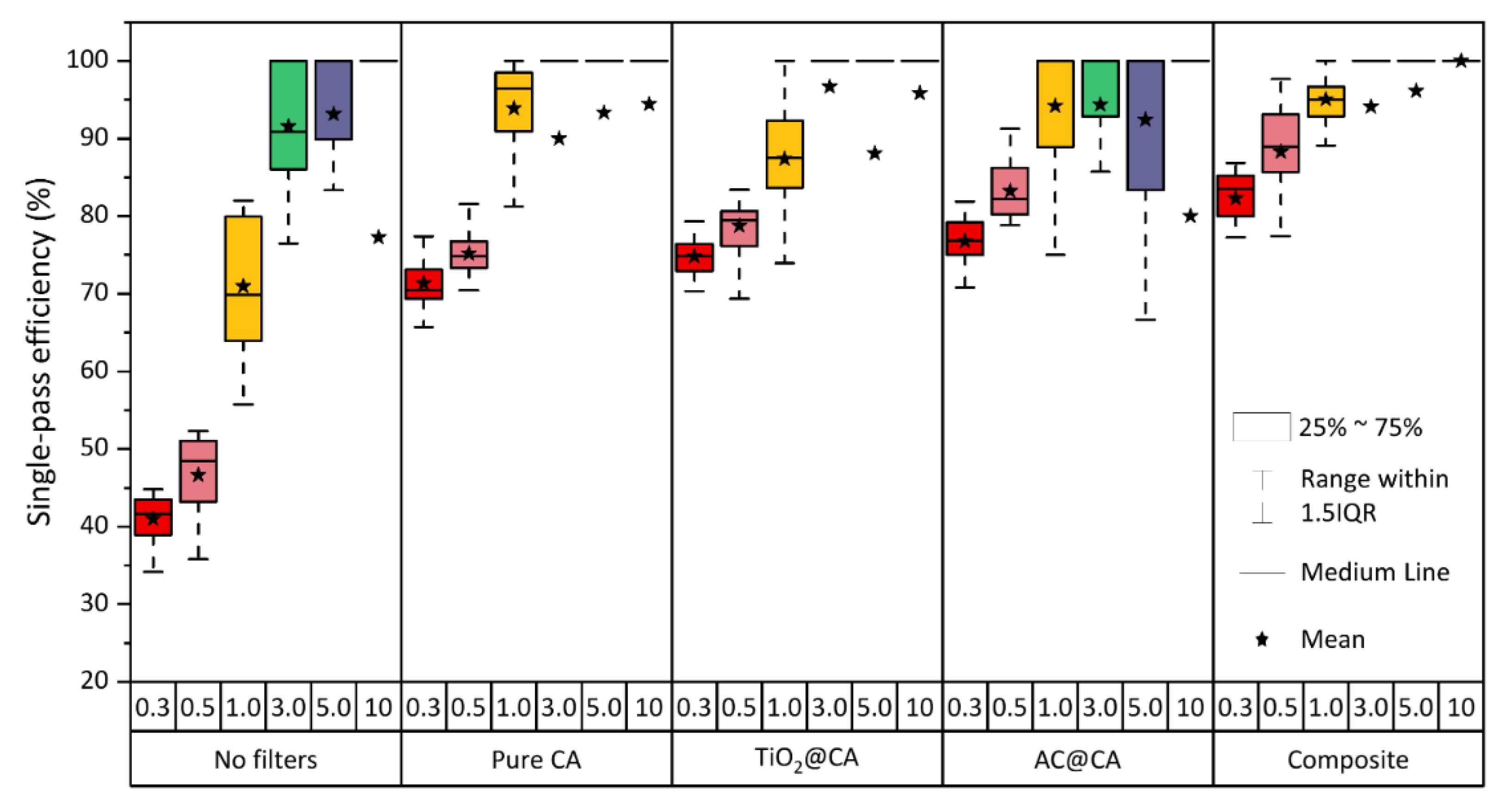
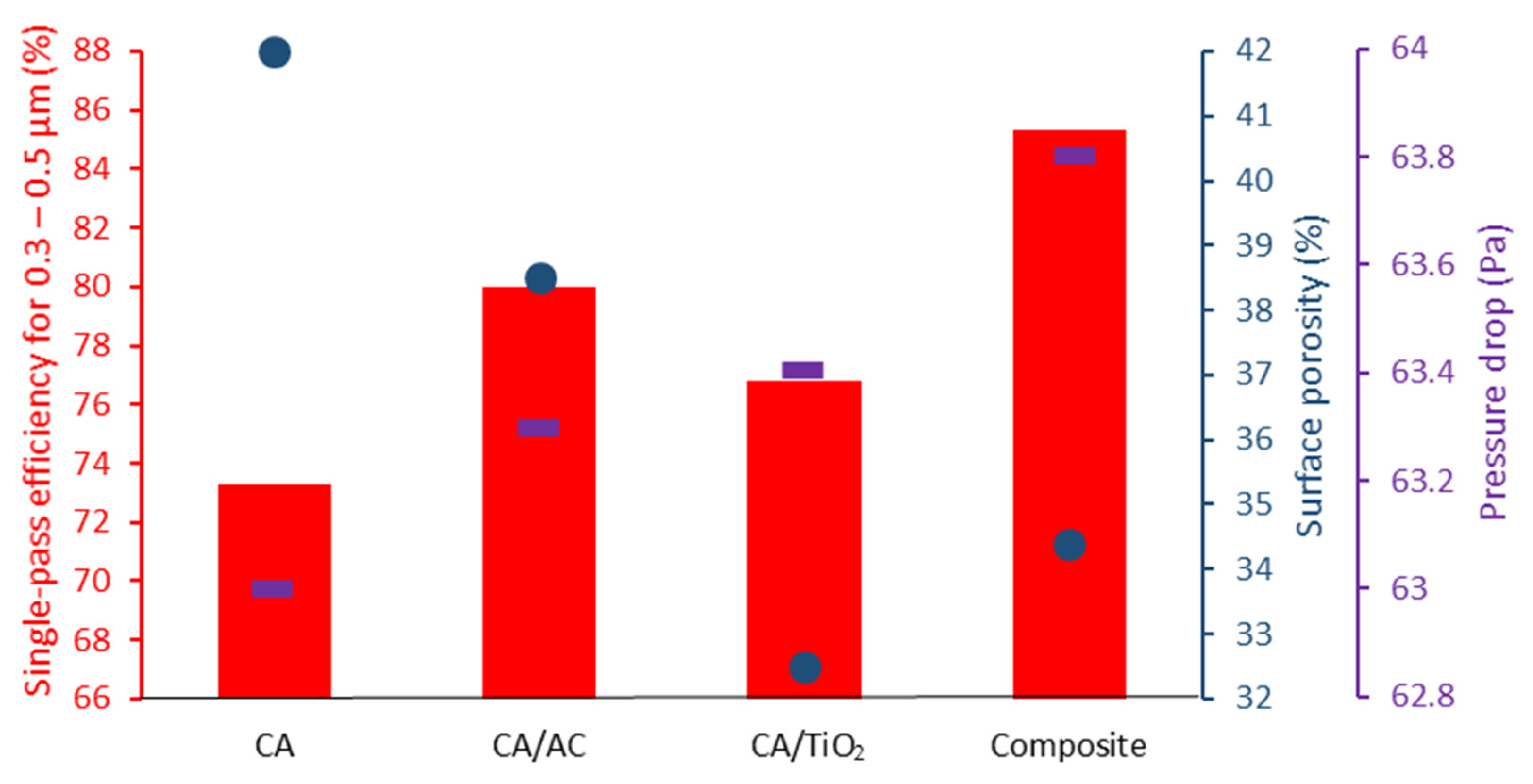
3.3.2. Particle Filtration Efficiency

The results of the filtration efficiency of the four different filters are presented in Figure 8. The face velocity was set at 0.8 m s−1. The air temperature and relative humidity were measured at 22.4 °C and 36.2%.
The charging module was investigated in terms of particle removal without the use of any filter. It recorded a peak removal capacity towards 3.0–5.0 µm particle size (above 90%), while smaller particles (0.3⁠–0.5 µm) easily penetrated it, and the removal capacity fell below 47%. Medium-sized particles between 0.5 and 3 µm and large particles between 5 and 10 µm have been removed with an efficiency of 71% and 77.3%, respectively.
The use of the filters had an impact on filtration of all particle sizes, with the most significant improvements registered for the smaller and most harmful particles. As visible from the graph in Figure 8, all ultrathin filters have recorded particle filtration efficiency above 70%. In accordance with the concept of most penetrating particle size (MPPS), the smaller particles penetrate the filters more, resulting in a decreased mean filtration efficiency for 0.3 to 0.5 µm particles compared to larger particle sizes. For particles between 1 and 10 µm diameter, the filters have recorded filtration efficiencies above 90%.
Comparing the performance across the different ultrathin filters, the use of additives affected the filtration capacity. The major and most important impact is again on the filtration of small charged particles between 0.3 and 0.5 µm diameter. The CA/AC and CA/TiO2 filters recorded an increased filtration efficiency of 9.2% and 4.8 %, respectively, compared to the pure CA filter. The composite filter registered the best performance with an improvement of 16.4%. Moving towards the larger particles, the pure CA filter also performed well in comparison with the CA/AC and CA/TiO2 filters. The composite filter again achieved the best performance, with 95% removal of particles around 1 µm size and achieving 100% removal of the largest particles between 5 and 10 µm.
Figure 9 shows the relationship between single-pass filtration efficiency for 0.3–0.5 µm particle size, surface porosity, and pressure drop. As supposed, the general tendency demonstrates that the higher the surface porosity, the lower the filtration efficiency and the pressure drop. The CA/TiO2 filter does not completely follow the trend because it has shown a lower efficiency compared to CA/AC filter, despite a lower porosity. The difference in the effect seen between AC and TiO2 surface-modified filters, apart from their differences in surface porosity, is in the inherent nature of the modifying material. AC renders the filter material more hydrophobic, whereas TiO2 adds negative charges to the filter surface. As it can be seen in Figure 9, the hydrophobic effect surpasses the effect of the negative charge of TiO2 and thereby renders the CA/AC filter better suited than the CA/TiO2 filter.
Table 3 also shows the calculated quality factor for each of the filters. These parameters give a clear understanding of which filter best optimised the ratio between filtration efficiency and pressure drop. The result revealed that the composite filter best optimises this ratio when comparing it with the other filters developed in this work. The combination of activated charcoal and titanium dioxide in a composite filter reached a considerably higher filtration efficiency at the cost of a slightly increased pressure drop.
Data have been collected from other studies in order to compare the filtration performance of different filters at a face velocity of 0.8 m s−1, as reported in Table 4. The filtration efficiency is related to particle sizes between 0.3 and 0.5 μm, and this criterion has been used to select the studies in the literature. In their study, Xia et al. have also highlighted that most of the electrospun fibre filters were evaluated at very low face velocities [25]. In order to compare the studies in the literature with the filter fabricated in this study, pressure drops have been recalculated, assuming a proportional relationship with face velocities [25]. The composite filter developed for this work shows a high-quality factor compared to the others. Only one sample from the study of Zhang et al. has achieved a higher quality factor [43]. The filtration efficiency of the ultrathin composite material is lower compared to the samples from other studies, which instead reached significantly higher pressure drops. The main difference lies in the average fibre diameter of the fabricated composite material and the use of the charging module in order to ensure a uniform charge on the particles. The micro-dimension of the fibres and the use of additives have contributed to forming a surface porosity able to maintain the balance between pressure drop and filtration capacity while using a single ultrathin layer of filter material. The final result is that the composite filter kept a low pressure drop and achieved a relatively high filtration efficiency, optimising the quality factor compared to other electrospun fibre materials.

4. Conclusions

In summary, four ultrathin CA-based electrospun fibre filters were fabricated, achieving various configurations with the addition of AC and TiO2, separately and combined. The filters presented an average fibre diameter of 4.2 µm and a surface porosity between 32.5 and 42%. The use of additives has led to an overall rougher fibre morphology and lower surface porosity compared to the undoped CA filter, reaching an increased particle filtration and a slightly higher pressure drop. The filters presented ultralow pressure drops between 3 and 3.3 Pa at 5.3 cm s−1 face velocity. The pure CA filter had a thickness of 0.14 mm and achieved a filtration efficiency of 73.3% for charged particles between 0.3 and 0.5 μm. The filtration efficiencies improved with the use of the additives. The composite filter, in which both AC and TiO2 nanoparticles were embedded, demonstrated a thickness of 0.18 mm and presented a filtration efficiency of 82% for charged particles sized between 0.3 and 0.5 μm, reaching 100% removal of 10 μm particles, at the cost of a pressure drop of 63.8 Pa at 0.8 m s−1 face velocity. This study showed the positive impact of additives on the particle filtration performance of ultrathin electrospun fibre filters. The ultrathin CA based-composite filter presented filtration performances and quality factors that are significantly improved compared to other electrospun fibre filters found in the literature today.

Author Contributions

Conceptualisation, R.O., P.F. and A.A.; methodology, R.O., Y.G., P.F. and J.M.; validation, R.O., Y.G., P.F. and J.M.; formal analysis, R.O. and Y.G.; investigation, R.O. and Y.G.; resources, P.F. and J.M.; writing—original draft preparation, R.O.; writing—review and editing, all authors; visualisation, R.O. and Y.G.; supervision, A.A., P.F., J.M.; project administration, A.A. and P.F.; funding acquisition, A.A. and P.F. All authors have read and agreed to the published version of the manuscript.

Funding

This research was funded by Grundejernes Investeringsfond, the Department of the Built Environment, and the Department of Materials and Production at Aalborg University. The research was financially supported by the National Natural Science Foundation of China (No. 52078269).

Acknowledgments

The authors thank research technician Peter Kjær Kristensen from the Department of Materials and Production at Aalborg University for his support in performing the SEM images.

Conflicts of Interest

The authors declare no conflict of interest. The funders had no role in the design of the study; in the collection, analyses, or interpretation of data; in the writing of the manuscript, or in the decision to publish the results.

References

  1. Mills, N.L.; Donaldson, K.; Hadoke, P.W.; Boon, N.A.; MacNee, W.; Cassee, F.R.; Sandström, T.; Blomberg, A.; Newby, D.E. Adverse cardiovascular effects of air pollution. Nat. Clin. Pr. Neurol. 2008, 6, 36–44. [Google Scholar] [CrossRef]
  2. Brunekreef, B.; Holgate, S.T. Air pollution and health. Lancet 2002, 360, 1233–1242. [Google Scholar] [CrossRef]
  3. Pope, C.A., 3rd; Dockery, D.W. Health Effects of Fine Particulate Air Pollution: Lines that Connect. J. Air Waste Manag. Assoc. 2006, 56, 709–742. [Google Scholar] [CrossRef]
  4. Katsouyanni, K.; Touloumi, G.; Samoli, E.; Gryparis, A.; Le Tertre, A.; Monopolis, Y.; Rossi, G.; Zmirou, D.; Ballester, F.; Boumghar, A.; et al. Confounding and Effect Modification in the Short-Term Effects of Ambient Particles on Total Mortality: Results from 29 European Cities within the APHEA2 Project. Epidemiology 2001, 12, 521–531. [Google Scholar] [CrossRef] [Green Version]
  5. World Health Organization. WHO Global Air Quality Guidelines. Particulate Matter (PM2.5 and PM10), Ozone, Nitrogen Dioxide, Sulfur Dioxide and Carbon Monoxide; WHO: Geneva, Switzerland, 2021. [Google Scholar]
  6. Xia, T.; Chen, C. Differentiating between indoor exposure to PM2.5 of indoor and outdoor origin using time-resolved monitoring data. Build. Environ. 2019, 147, 528–539. [Google Scholar] [CrossRef]
  7. Chen, C.; Zhao, B. Review of relationship between indoor and outdoor particles: I/O ratio, infiltration factor and penetration factor. Atmos. Environ. 2011, 45, 275–288. [Google Scholar] [CrossRef]
  8. Fazli, T.; Zeng, Y.; Stephens, B. Fine and ultrafine particle removal efficiency of new residential HVAC filters. Indoor Air 2019, 29, 656–669. [Google Scholar] [CrossRef]
  9. Brincat, J.-P.; Sardella, D.; Muscat, A.; Decelis, S.; Grima, J.; Valdramidis, V.; Gatt, R. A review of the state-of-the-art in air filtration technologies as may be applied to cold storage warehouses. Trends Food Sci. Technol. 2016, 50, 175–185. [Google Scholar] [CrossRef]
  10. Stephens, B.; Siegel, J.A. Ultrafine particle removal by residential heating, ventilating, and air-conditioning filters. Indoor Air 2013, 23, 488–497. [Google Scholar] [CrossRef] [PubMed]
  11. ASME. Addenda to ASME AG-1–2003 Code on Nuclear Air and Gas Treatment; ASME: New York, NY, USA, 2004. [Google Scholar]
  12. Bourrous, S.; Bouilloux, L.; Ouf, F.-X.; Lemaitre, P.; Nerisson, P.; Thomas, D.; Appert-Collin, J.-C. Measurement and modeling of pressure drop of HEPA filters clogged with ultrafine particles. Powder Technol. 2016, 289, 109–117. [Google Scholar] [CrossRef]
  13. Ardkapan, S.R.; Johnson, M.S.; Yazdi, S.; Afshari, A.; Bergsøe, N.C. Filtration efficiency of an electrostatic fibrous filter: Studying filtration dependency on ultrafine particle exposure and composition. J. Aerosol Sci. 2014, 72, 14–20. [Google Scholar] [CrossRef]
  14. COAG. Guide to Best Practice Maintenance & Operation of HVAC Systems for Energy Efficiency; COAG: Canberra, ACT, Australia, 2012.
  15. Stephens, B.; Siegel, J.A.; Novoselac, A. Energy implications of filtration in residential and light-commercial buildings. Ashrae Trans. 2010, 116, 346–357. [Google Scholar]
  16. Li, D.; Xia, Y. Electrospinning of Nanofibers: Reinventing the Wheel? Adv. Mater. 2004, 16, 1151–1170. [Google Scholar] [CrossRef]
  17. Zhao, X.; Wang, S.; Yin, X.; Yu, J.; Ding, B. Slip-Effect Functional Air Filter for Efficient Purification of PM2.5. Sci. Rep. 2016, 6, 35472. [Google Scholar] [CrossRef] [PubMed]
  18. Shou, D.; Ye, L.; Fan, J. Gas transport properties of electrospun polymer nanofibers. Polymer 2014, 55, 3149–3155. [Google Scholar] [CrossRef]
  19. Li, Y.; Yin, X.; Yu, J.; Ding, B. Electrospun nanofibers for high-performance air filtration. Compos. Commun. 2019, 15, 6–19. [Google Scholar] [CrossRef]
  20. Zhu, M.; Han, J.; Wang, F.; Shao, W.; Xiong, R.; Zhang, Q.; Pan, H.; Yang, Y.; Samal, S.K.; Zhang, F.; et al. Electrospun Nanofibers Membranes for Effective Air Filtration. Macromol. Mater. Eng. 2017, 302, 1600353. [Google Scholar] [CrossRef]
  21. Bian, Y.; Wang, R.; Ting, S.H.; Chen, C.; Zhang, L. Electrospun SF/PVA Nanofiber Filters for Highly Efficient PM2.5 Capture. IEEE Trans. Nanotechnol. 2018, 17, 934–939. [Google Scholar] [CrossRef]
  22. Niu, Z.; Bian, Y.; Xia, T.; Zhang, L.; Chen, C. An optimization approach for fabricating electrospun nanofiber air filters with minimized pressure drop for indoor PM2.5 control. Build. Environ. 2021, 188, 107449. [Google Scholar] [CrossRef]
  23. Topuz, F.; Abdulhamid, M.A.; Hardian, R.; Holtzl, T.; Szekely, G. Nanofibrous membranes comprising intrinsically microporous polyimides with embedded metal–organic frameworks for capturing volatile organic compounds. J. Hazard. Mater. 2021, 424, 127347. [Google Scholar] [CrossRef]
  24. Kumar, S.; Jang, J.; Oh, H.; Jung, B.J.; Lee, Y.; Park, H.; Yang, K.H.; Seong, Y.C.; Lee, J.-S. Antibacterial Polymeric Nanofibers from Zwitterionic Terpolymers by Electrospinning for Air Filtration. ACS Appl. Nano Mater. 2021, 4, 2375–2385. [Google Scholar] [CrossRef]
  25. Xia, T.; Bian, Y.; Zhang, L.; Chen, C. Relationship between pressure drop and face velocity for electrospun nanofiber filters. Energy Build. 2018, 158, 987–999. [Google Scholar] [CrossRef]
  26. Wan, H.; Wang, N.; Yang, J.; Si, Y.; Chen, K.; Ding, B.; Sun, G.; El-Newehy, M.; Al-Deyab, S.S.; Yu, J. Hierarchically structured polysulfone/titania fibrous membranes with enhanced air filtration performance. J. Colloid Interface Sci. 2014, 417, 18–26. [Google Scholar] [CrossRef] [PubMed]
  27. Tian, M.-J.; Liao, F.; Ke, Q.-F.; Guo, Y.-P. Synergetic effect of titanium dioxide ultralong nanofibers and activated carbon fibers on adsorption and photodegradation of toluene. Chem. Eng. J. 2017, 328, 962–976. [Google Scholar] [CrossRef]
  28. Ao, C.; Lee, S.-C. Indoor air purification by photocatalyst TiO2 immobilized on an activated carbon filter installed in an air cleaner. Chem. Eng. Sci. 2005, 60, 103–109. [Google Scholar] [CrossRef]
  29. Chuang, Y.-H.; Hong, G.-B.; Chang, C.-T. Study on particulates and volatile organic compounds removal with TiO2 nonwoven filter prepared by electrospinning. J. Air Waste Manag. Assoc. 2014, 64, 738–742. [Google Scholar] [CrossRef]
  30. Shi, B.; Ekberg, L. Ionizer Assisted Air Filtration for Collection of Submicron and Ultrafine Particles—Evaluation of Long-Term Performance and Influencing Factors. Environ. Sci. Technol. 2015, 49, 6891–6898. [Google Scholar] [CrossRef]
  31. Park, J.H.; Yoon, K.Y.; Hwang, J. Removal of submicron particles using a carbon fiber ionizer-assisted medium air filter in a heating, ventilation, and air-conditioning (HVAC) system. Build. Environ. 2011, 46, 1699–1708. [Google Scholar] [CrossRef]
  32. Agranovski, I.E.; Huang, R.; Pyankov, O.V.; Altman, I.S.; Grinshpun, S.A. Enhancement of the Performance of Low-Efficiency HVAC Filters Due to Continuous Unipolar Ion Emission. Aerosol Sci. Technol. 2006, 40, 963–968. [Google Scholar] [CrossRef]
  33. Tian, E.; Mo, J. Toward energy saving and high efficiency through an optimized use of a PET coarse filter: The development of a new electrostatically assisted air filter. Energy Build. 2019, 186, 276–283. [Google Scholar] [CrossRef]
  34. Tian, E.; Yu, Q.; Gao, Y.; Wang, H.; Wang, C.; Zhang, Y.; Li, B.; Zhu, M.; Mo, J.; Xu, G.; et al. Ultralow Resistance Two-Stage Electrostatically Assisted Air Filtration by Polydopamine Coated PET Coarse Filter. Small 2021, 17, 2102051. [Google Scholar] [CrossRef]
  35. Xia, F.; Gao, Y.; Tian, E.; Afshari, A.; Mo, J. Fast fabricating cross-linked nanofibers into flameproof metal foam by air-drawn electrospinning for electrostatically assisted particle removal. Sep. Purif. Technol. 2021, 274, 119076. [Google Scholar] [CrossRef]
  36. Gao, Y.; Tian, E.; Mo, J. Electrically Responsive Coarse Filters Endowed by High-Dielectric-Constant Surface Coatings toward Efficient Removal of Ultrafine Particles and Ozone. ACS ES&T Eng. 2021, 1, 1449–1459. [Google Scholar] [CrossRef]
  37. Entcheva, E.; Bien, H.; Yin, L.; Chung, C.Y.; Farrell, M.; Kostov, Y. Functional cardiac cell constructs on cellulose-based scaffolding. Biomaterials 2004, 25, 5753–5762. [Google Scholar] [CrossRef] [PubMed]
  38. Kwon, M.; Kim, J.; Kim, J. Photocatalytic activity and filtration performance of hybrid TiO2-cellulose acetate nanofibers for air filter applications. Polymers 2021, 13, 1331. [Google Scholar] [CrossRef]
  39. Christoforou, T.; Doumanidis, C. Biodegradable cellulose acetate nanofiber fabrication via electrospinning. J. Nanosci. Nanotechnol. 2010, 10, 6226–6233. [Google Scholar] [CrossRef] [PubMed]
  40. Su, J.; Yang, G.; Cheng, C.; Huang, C.; Xu, H.; Ke, Q. Hierarchically structured TiO2/PAN nanofibrous membranes for high-efficiency air filtration and toluene degradation. J. Colloid Interface Sci. 2017, 507, 386–396. [Google Scholar] [CrossRef]
  41. Qin, X.-H.; Wang, S.-Y. Electrospun nanofibers from crosslinked poly(vinyl alcohol) and its filtration efficiency. J. Appl. Polym. Sci. 2008, 109, 951–956. [Google Scholar] [CrossRef]
  42. Guibo, Y.; Qing, Z.; Yahong, Z.; Yin, Y.; Yumin, Y. The electrospun polyamide 6 nanofiber membranes used as high efficiency filter materials: Filtration potential, thermal treatment, and their continuous production. J. Appl. Polym. Sci. 2013, 128, 1061–1069. [Google Scholar] [CrossRef]
  43. Zhang, R.; Liu, C.; Hsu, P.-C.; Zhang, C.; Liu, N.; Zhang, J.; Lee, H.R.; Lu, Y.; Qiu, Y.; Chu, S.; et al. Nanofiber Air Filters with High-Temperature Stability for Efficient PM2.5 Removal from the Pollution Sources. Nano Lett. 2016, 16, 3642–3649. [Google Scholar] [CrossRef]
  44. Zhu, M.; Hua, D.; Pan, H.; Wang, F.; Manshian, B.; Soenen, S.; Xiong, R.; Huang, C. Green electrospun and crosslinked poly(vinyl alcohol)/poly(acrylic acid) composite membranes for antibacterial effective air filtration. J. Colloid Interface Sci. 2018, 511, 411–423. [Google Scholar] [CrossRef] [PubMed]
  45. Zhang, S.; Tang, N.; Cao, L.; Yin, X.; Yu, J.; Ding, B. Highly Integrated Polysulfone/Polyacrylonitrile/Polyamide-6 Air Filter for Multilevel Physical Sieving Airborne Particles. ACS Appl. Mater. Interfaces 2016, 8, 29062–29072. [Google Scholar] [CrossRef] [PubMed]
  46. Kim, G.T.; Ahn, Y.C.; Lee, J.K. Characteristics of Nylon 6 nanofilter for removing ultra fine particles. Korean J. Chem. Eng. 2008, 25, 368–372. [Google Scholar] [CrossRef]
  47. Wang, N.; Si, Y.; Wang, N.; Sun, G.; El-Newehy, M.; Al-Deyab, S.S.; Ding, B. Multilevel structured polyacrylonitrile/silica nanofibrous membranes for high-performance air filtration. Sep. Purif. Technol. 2014, 126, 44–51. [Google Scholar] [CrossRef]
Figure 1. Schematic representation of the electrospinning setup.
Buildings 11 00557 g001
Figure 2. Schematic setup representation. 1. Diffusion plate, 2. Sampler, 3. Charging pins, 4. Metal rings, 5. HVDC power, 6. Anemometer, 7. Differential pressure sensor, 8. Metal mesh, 9. Membrane, 10. Fan and frequency converter.
Buildings 11 00557 g002
Figure 3. Real image of the setup used to investigate the filtration performance of the filter materials.
Buildings 11 00557 g003
Figure 4. Electrospun filter materials developed in this study: (a) pure CA; (b) CA/AC; (c) CA/TiO2; (d) composite.
Buildings 11 00557 g004
Figure 5. SEM images of the different electrospun fibre materials: (a) pure CA; (b) CA/AC; (c) CA/TiO2.
Buildings 11 00557 g005
Figure 6. SEM images of the composite filter divided into the four layers of fabrication: (a) 1st layer, CA fibres; (b) 2nd layer, AC spray; (c) 3rd layer, CA fibres; (d) 4th layer, TiO2 spray.
Buildings 11 00557 g006
Figure 7. Mean fibre diameter distribution.
Buildings 11 00557 g007
Figure 8. Particle filtration efficiency for the different filters per particle size.
Buildings 11 00557 g008
Figure 9. Single-pass filtration efficiency for particle size between 0.3 and 0.5 µm, surface porosity, and pressure drop.
Buildings 11 00557 g009
Table 1. Solution, process, and environmental parameters that were used during the electrospinning of CA solution.
Solution ParametersProcess ParametersEnvironmental Parameters
CA ConcentrationSolventTip-to-Collector DistanceVoltageFeed RateNeedle Inner ØTemperatureRelative Humidity
12.5 w/v%Acetone9 cm14.8 kV1 mL min−11.5 mm21 °C ± 0.5 °C37% ± 3%
Table 2. Results from the analysis of the filter porosity and thickness.
CACA/ACCA/TiO2Composite
Surface porosity (%)42.0 ± 5.438.5 ± 2.632.5 ± 5.134.4 ± 4.5
Thickness (mm)0.11 ± 0.0160.14 ± 0.0120.15 ± 0.0050.18 ± 0.007
Table 3. Pressure drop results for the different filters at different face velocities. Filtration efficiency to particle size between 0.3 and 0.5 µm and related quality factor calculated with pressure drop at 0.8 m s−1 face velocity.
Filter0.035 m s−10.053 m s−10.069 m s−10.087 m s−10.8 m s−11 m s−1 η QF
CA3 Pa3.5 Pa4.7 Pa6.6 Pa63.0 Pa74.1 Pa73.3% ± 3.1%0.020 Pa1
CA/AC3.2 Pa3.7 Pa4.9 Pa6.8 Pa63.3 Pa74.7 Pa80% ± 3.2%0.023 Pa1
CA/TiO23.2 Pa3.7 Pa4.9 Pa7.0 Pa63.4 Pa74.8 Pa76.8% ± 3.1%0.022 Pa1
Composite3.3 Pa3.8 Pa5.1 Pa7.0 Pa63.8 Pa75.3 Pa85.3% ± 5.9%0.027 Pa1
Table 4. Comparison of filtration efficiency for particle size between 0.3 and 0.5 μm, pressure drop and quality factor at 0.8 m s−1 with studies in the literature.
CaseParticle Filtration Efficiency
(0.3–0.5 μm) (%)
Pressure Drop (Pa)QF (Pa1)MaterialRef
199.982430.0351Polyimide nanofibres[43]
29819970.0019Poly(vinyl alcohol)/Poly(acrylic acid) + silica and silver nanoparticles[44]
399.99217810.0053Polysulfone/Polyacrylonitrile/Polyamide 6[45]
499.9977250.0143Polysulfone/TiO2 fibrous membrane[26]
599.9943150.0021Nylon 6 nanofibre[46]
699.9896590.0138Polyacrylonitrile/silica nanoparticles[47]
782.363.80.0271Composite filter CA/AC/CA/TiO2This work
Publisher’s Note: MDPI stays neutral with regard to jurisdictional claims in published maps and institutional affiliations.

