Article

Seismic Vulnerability of Sub-Structures: Vantitelli’s Modulus in Murena Palace

by
Vittorio Gusella
and
Riccardo Liberotti
*
Department of Civil and Environmental Engineering, University of Perugia, 06125 Perugia, Italy
*
Author to whom correspondence should be addressed.
Buildings 2020, 10(9), 164; https://doi.org/10.3390/buildings10090164
Submission received: 27 July 2020 / Revised: 7 September 2020 / Accepted: 9 September 2020 / Published: 13 September 2020
(This article belongs to the Collection Structural Analysis for Earthquake-Resistant Design of Buildings)

Abstract

:
This paper focuses on the Murena Palace in Perugia, part of an architectural complex designed by Luigi Vanvitelli and completed by Carlo Murena in the 18th century. In the context of the seismic vulnerability assessment of this masonry building, the safety of a construction modulus, which gathers several peculiar features identified within the edifice, is analyzed by means of an integrated architectural-structural approach. This construction modulus, that will be called Vanvitelli’s Modulus, is characterized by an intrinsic structural asymmetry with clusters of rooms with masonry vaults, combining different heights, where load bearing walls are standing on top of the vaults. Given these peculiarities, this construction modulus has to be analyzed as a sub-structure with regards to the seismic vulnerability. To this purpose, experimental tests, in particular videoendoscopies and structural monitoring, were conducted to identify geometrical features of walls and vaults, mechanical characteristic of materials and the actual damage condition. From an accurate survey, an innovative parametric approach has been proposed to build the geometrical model of the construction modulus. This has been used, by FEM (finite element method), to perform a structural analysis whose results have been checked by comparison with the actual damage patterns. The proposed integrated architectural-structural approach permits a deeper comprehension of the structural principles that characterize Vanvitelli’s construction modulus and to estimate its seismic vulnerability.

1. Introduction

Recently, owing to the earthquakes that affected central Italy in the last few years, the University of Perugia activated a research program aimed at the seismic safety assessment of the historic buildings that are managed by it. This activity also involved its headquarters: the architectural complex of Murena Palace, Figure 1. This aggregate is composed by three adjacent buildings: Murena Palace, former a monastic complex (Figure 2—(1)), the Church of Montemorcino Nuovo or Church of the University, (Figure 2—(2)) and the ex-Accountancy Office (Figure 2—(3)).
With reference to Murena Palace, in a previous paper [1], a global seismic analysis was conducted by a macro-element approach [2,3]; the obtained results proved the good global functioning of the existing masonry structure, highlighting, according to the Italian Building Code [4,5], that Murena Palace ranks in a state deserving to be seismically improved in order to pledge its safety.
To accomplish the task of an adequate seismic vulnerability assessment, the analysis must account for the local mechanisms [6,7] and in particular the mechanisms of failure for masonry walls under the out-of-plane seismic loads.
However, examining in deep the architecture of the building, a sub-structure has been highlighted that is a cluster of rooms with barrel-vaults (or barrel-vaults closed by coves) combining volumes of different heights and with one or two stories directly neighboring eachother and, most notably, where load bearing walls stand on top of barrel vaults.
This cluster, that will be called “Vanvitelli’s Modulus” (in honor of the prominent architect Luigi Vanvitelli who designed such buildings), appears interesting from a structural point of view and influences the seismic behavior of the building. This paper reports the results of an ongoing research that, starting from a thorough analysis of the historical and architectural genesis of the building, considers its actual state (evaluated by means of survey, damage assessment, experimental tests, monitoring) and takes into account the safety under static and seismic loads.
A complete procedure, aimed at vulnerability estimation of heritage structures, has been developed considering the basic interactions among the historical knowledge, the experimental investigation tools and the finite element analysis supplemented by parametric geometrical modeling. In this contest, a new methodology, based on a new parametric generative algorithm implemented to assure an expeditious 3D modeling of the geometry of Vanvitelli’s construction modulus characterized by a wide variety of masonry vault’s typologies and sizes, is proposed. The obtained geometry can be easily translated in a FEM network to conduct structural analyses.
Given the peculiar characteristics of this architectural cluster, the proposed approach seeks to introduce the vulnerability analysis for a new structural scale (meso-scale) that can be considered intermediate between global (macro) and local (micro) ones.
Moreover, the presence of load bearing walls that, vertically located at higher floors, stand on vaults at the first floor represents an evident possibility of “domino-type progressive collapse”. This aspect leads to introduce the theme of the robustness of this masonry structure typology and the conceiving of strengthening interventions to increase it. Such a structural feature avoids progressive collapse following the collapse of one of the building’s components, reacting instead with damages proportionate to the cause and limited to the failure area without triggering a knock-on effect.

2. Materials and Methods

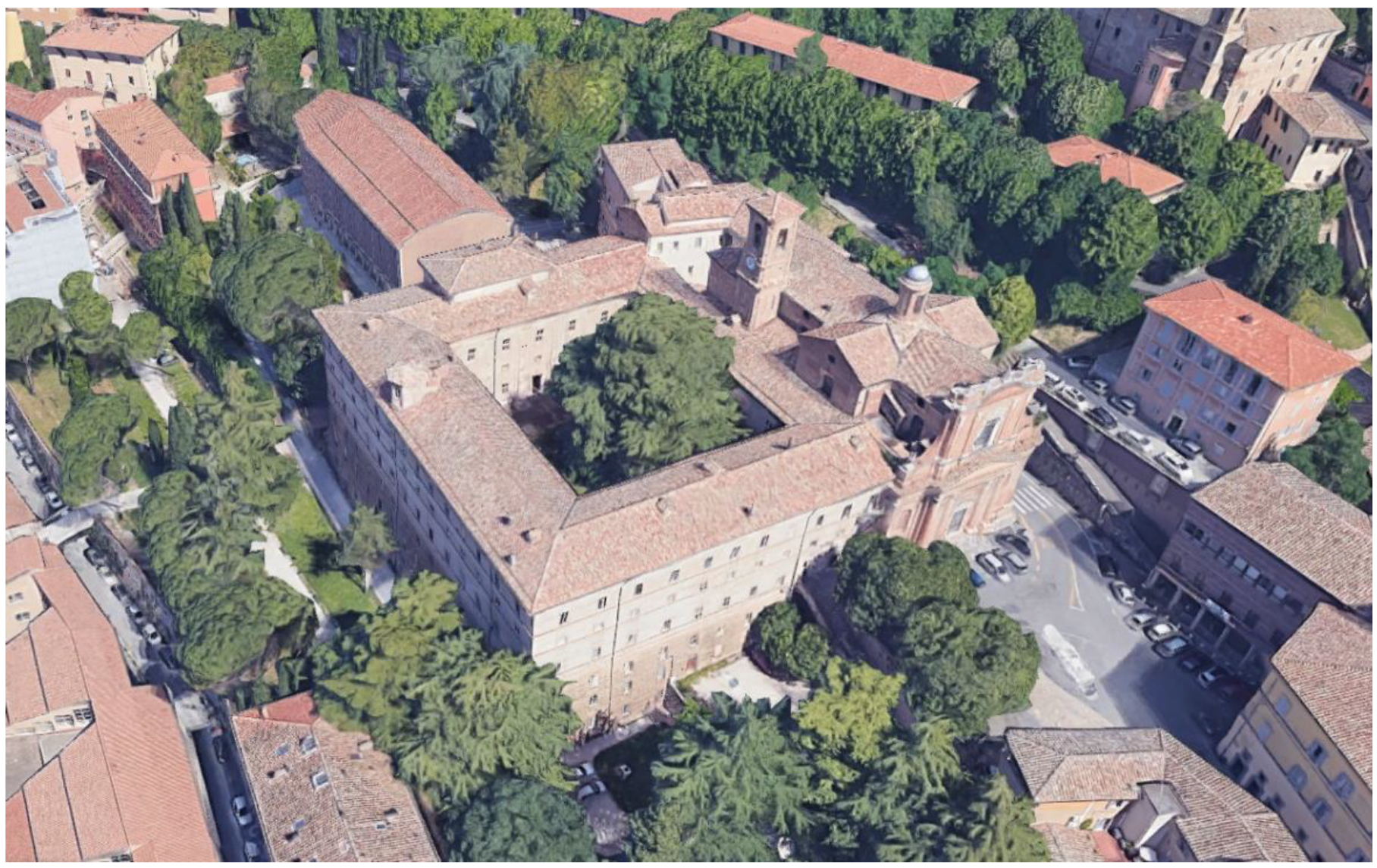
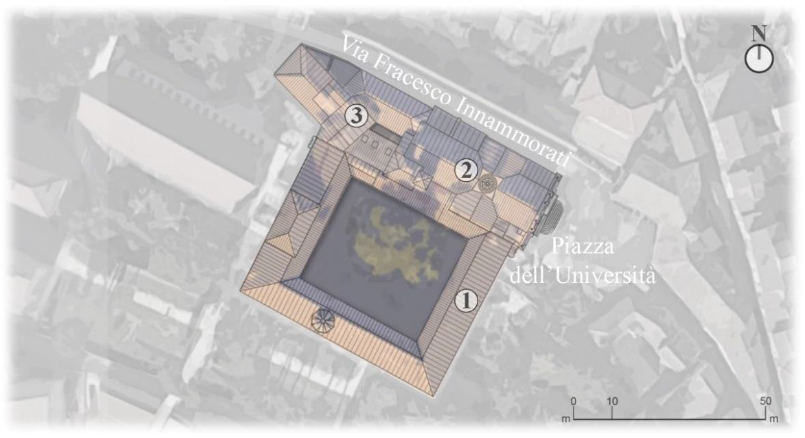
2.1. Historical Background and Surveys

Murena Palace has been the subject of a study, commissioned by the University of Perugia, aimed at an evaluation of its historical genesis in relationship with the adjacent buildings and at a better understanding of the architectural distribution. A first attempt in order to understand the technical and distributive reasons, which probably led to the realization of such a particular and articulated structure, has been made correlating what was previously observed to the multifaceted personal experience and the architectural canons of Luigi Vanvitelli. He was actually an Italian painter, scenographer and architect also renowned for his technical-constructive expertise that designed a conspicuous number of iconic buildings and that still today characterize the landscape of some Italian cities, e.g., the architectural complex of Caserta’s Royal Palace.
Murena Palace was once the Olivetan monastic complex, called Monte Morcino Nuovo, transferred from its former seat of Monte Morcino Vecchio, outside Santa Susanna, to the current University’s square. The monastery and the church of the Olivetans were designed by Luigi Vanvitelli and completed in 1762 by his pupil Carlo Murena, from whom the palace takes its current name. Vanvitelli’s contribution to the project of the Monte Morcino Nuovo has been witnessed by various bibliographical and archival historical sources [8].
Over recent centuries, a significant number of seismic events affected the city of Perugia. The I.N.G.V. (National Institute of Geophysics and Volcanology) provides information about the most relevant earthquakes which occurred in this area from the construction of Murena Palace; some significant seismic events among them are reported in Table 1.
In particular, the 1997 earthquake caused significant structural damages, which were mainly located in the northwest area of Palazzo Murena. After this event, the edifice was the object of a consolidation plan. So it appears clear that, during time, the building has undergone alteration, misuse or other changes to its as built/designed original state. Therefore, as a first step, it was necessary to understand whether the architectural-structural peculiarities, regarding the interior distribution, were the result of latter-day additions or not. The survey campaigns and the historical researches permitted to identify the main bearing structures and the secondary elements, also in relation to the transformations due to the change of the end use. Murena Palace is an imposing building designed as a quadrangular structure with a central courtyard and is characterized in elevation by multiple and regular openings, in contrast with the rich church’s facade. It was observed, during the surveys, that the building is divided into six floors; three floors are completely out of ground and the others are half-buried, since their only free sides are the ones facing the valley of the Conca, the ancient name for the district in which the building stands. The ground floor has rectangular shape, whose dimensions are about 60 m × 48 m, with the inner cloister having sides about 30 m × 33 m, Figure 2. The heights of the different levels are: 4.80 m for the third basement, 4.10 m for the second basement, 3.80 m for the first basement, 4.75 m for the ground floor, 3.10 for the mezzanine floor and 6.00 m for the first floor.

2.1.1. Genesis of Vanvitelli’s Modulus

The planimetric extension of the building varies from level to level, indicating an accentuated asymmetry especially regarding the elevation of the south and east wings of the palace. Indeed the ground floor plus the mezzanine floor entotal a height comparable to the lateral corridor. This masonry cluster of vaulted rooms, combining such different levels’ heights, creates situations, in the mezzanine floor, marked out by the presence of some carrying walls resting on the top of the barrel vaults. Three principal types of vaults can be observed: cross vaults, barrel vaults and barrel vaults closed by coves. Analysing that architectonical characteristics of the first and mezzanine floors, a representative masonry vault and wall cluster has been highlighted in Figure 3 and Figure 4 that shows, in relation to such selected masonries, the plan of the first floor and the mezzanine floor (see Figure 5).
This peculiarity, that once housed the monks’cells and the relative corridor of distribution, is not the result of a supplement following the original realization of the building factory but, thanks to the historical investigations, it has proved to be perfectly coeval with the design genesis operated by Luigi Vanvitelli as shown by comparison between Figure 6 and Figure 7. The structure proposed is an example of the creative flair and of the constructive expertise of the architect. In that case study, the need to satisfy a design objective has entailed, on Vanvitelli’s part, the design of an astonishing structural expedient that in the following will be identified as Vanvitelli’s Modulus. It must be noted that this construction modulus is characterized by “load bearing walls standing on vaults”, in the Italian language noted as “in falso”, i.e., walls that rest on a false foundation, relying for their support on the slabs; this is a solution that is adopted in other portions of Murena Palace. Moreover, the inner architectural composition made of double-volume spaces, characterized by a ground floor and a mezzanine floor realized within the height of the side corridor, and the use of load bearing walls standing on vaults, are hallmarks of different construction projects designed by Vanvitelli as the Royal Palace of Caserta, Figure 8.

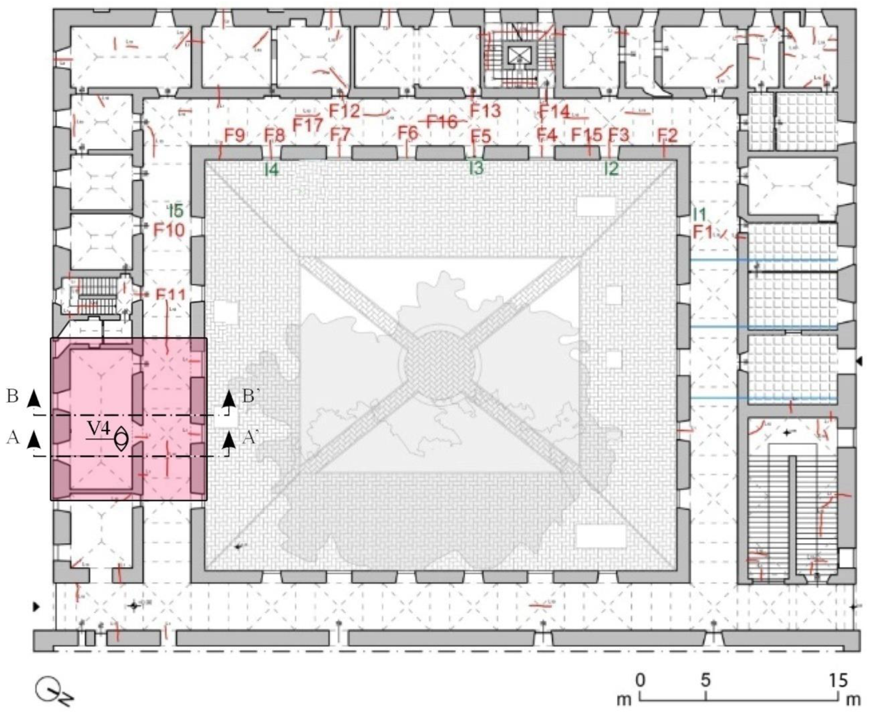
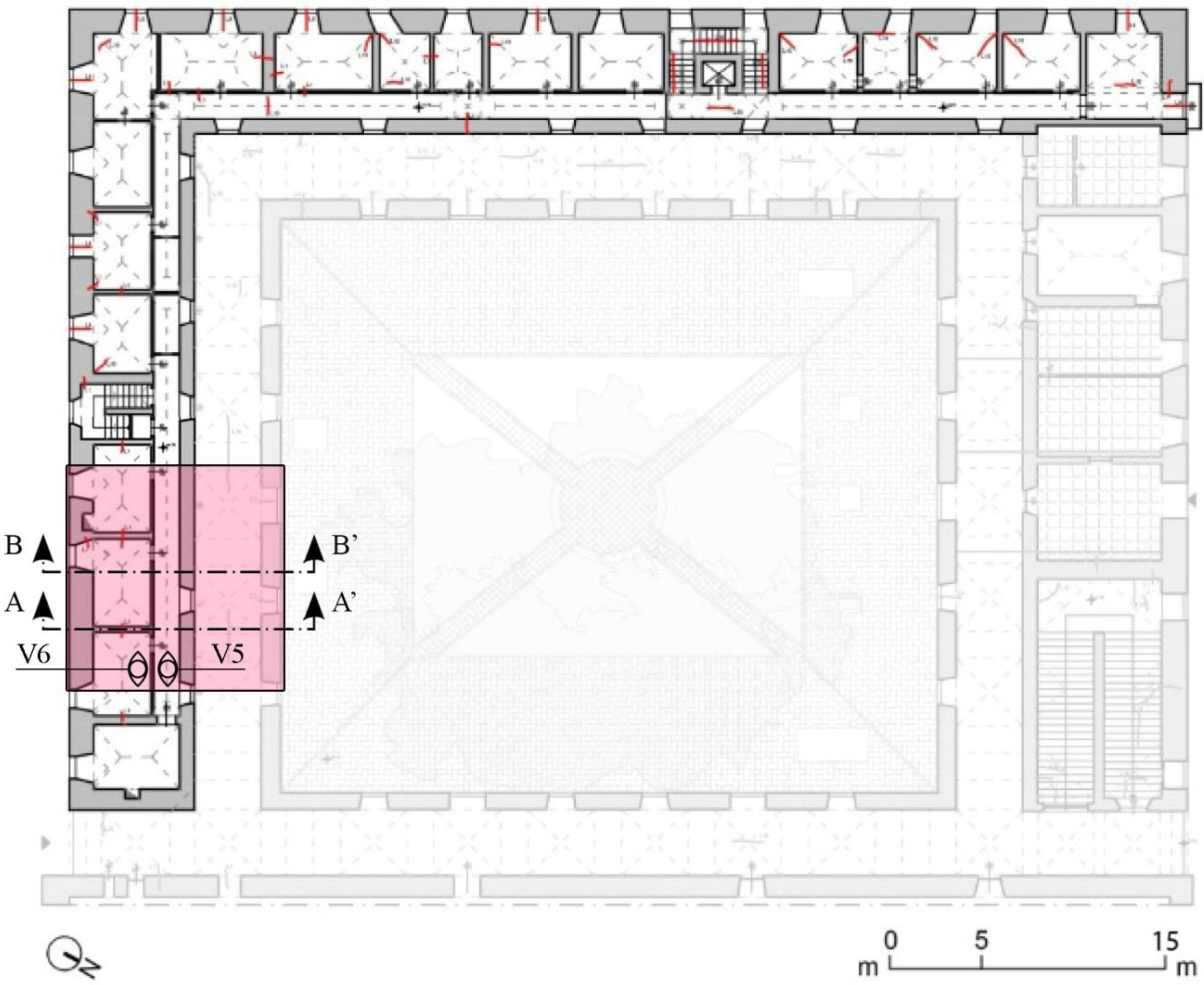
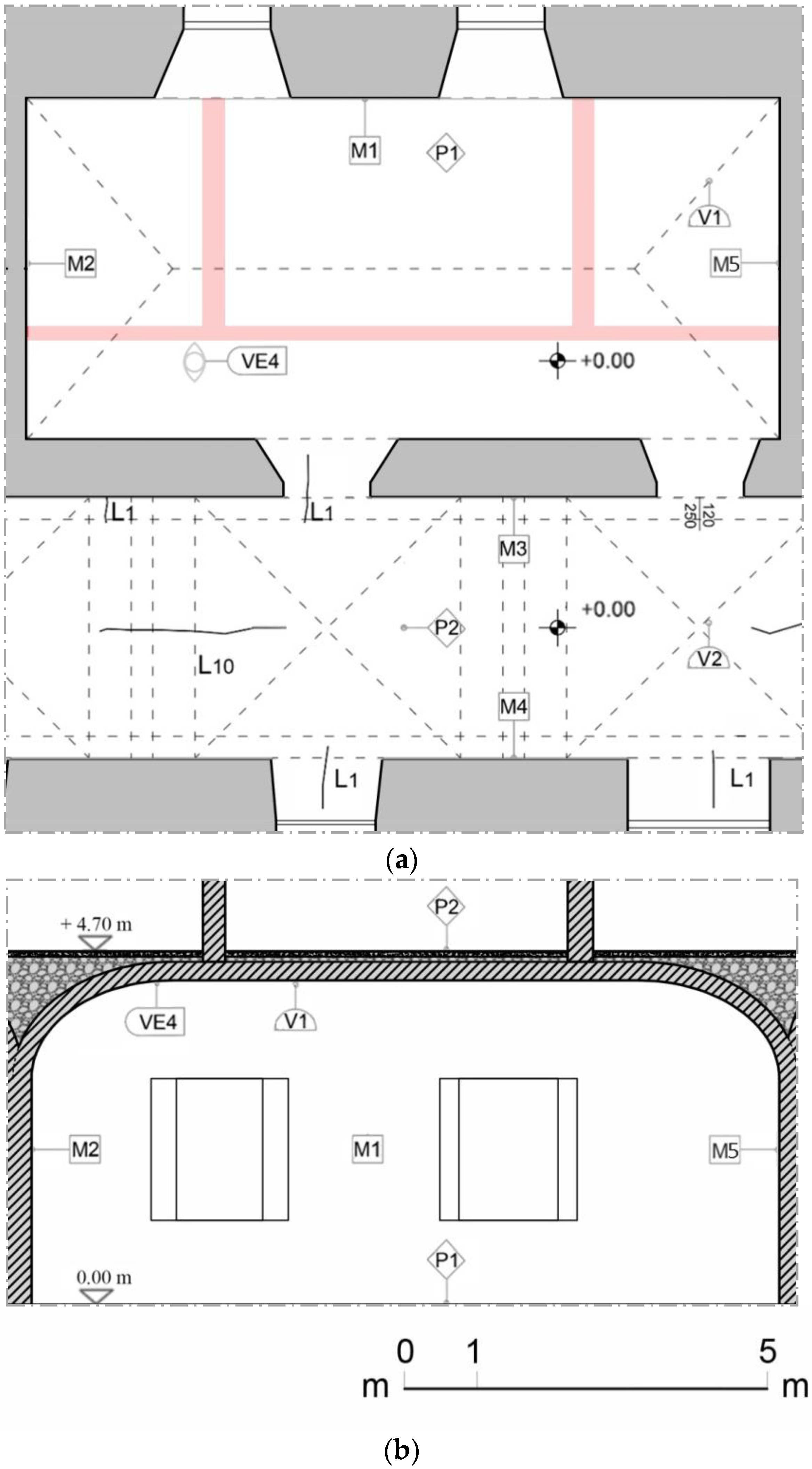
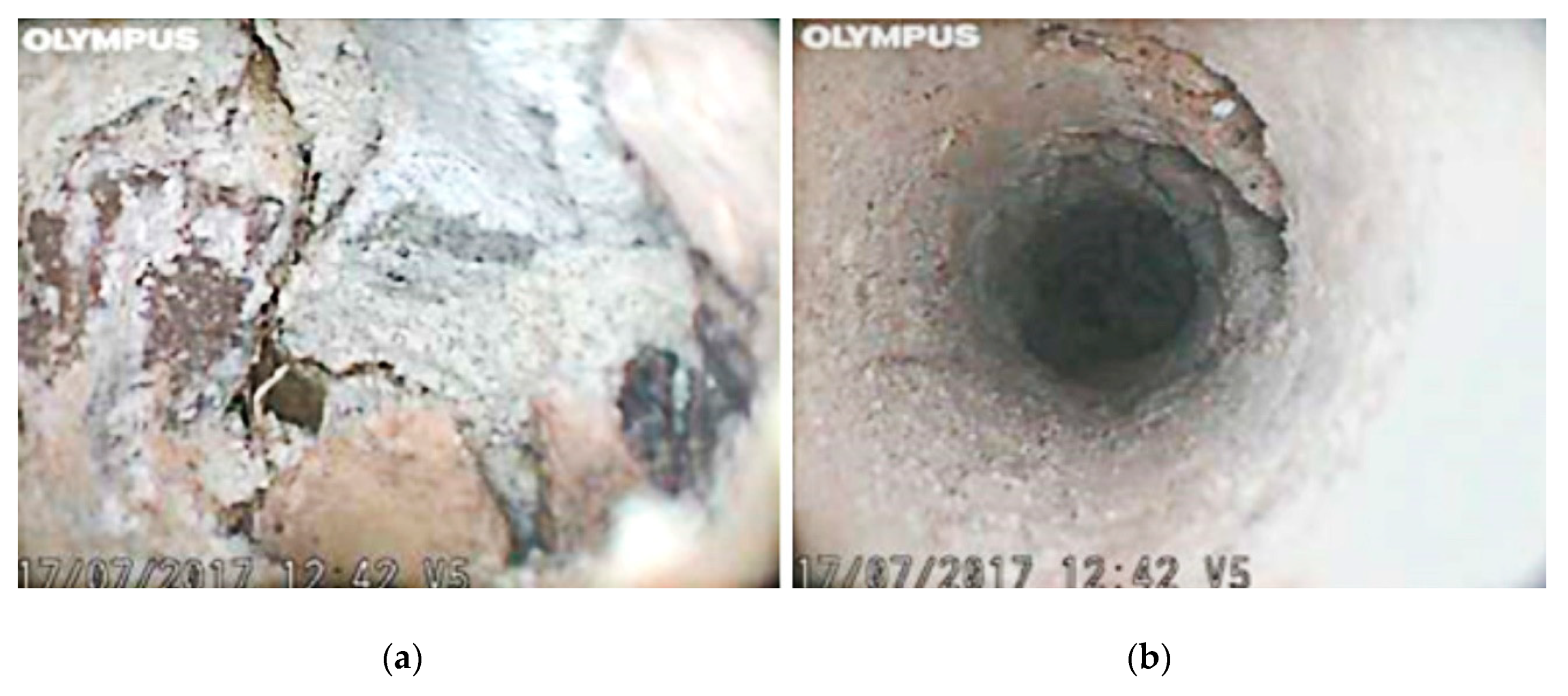
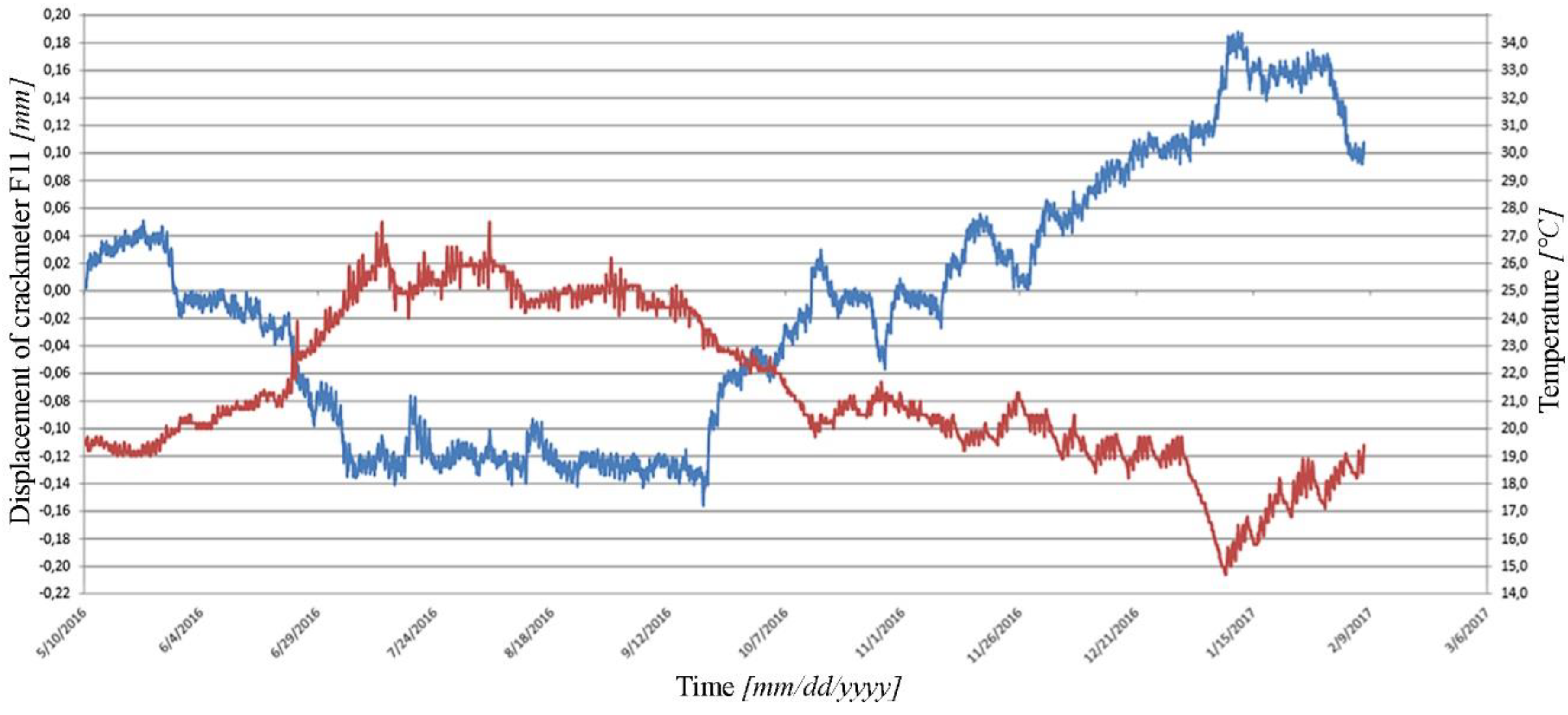
2.2. Actual State and Experimental Testing Campaign

Murena Palace has been subject to a surveying campaign aimed at an evaluation of its relationship with adjacent buildings and a better understanding of the structural main elements. With a view to a long term perspective, concerning the potential use of heritage building information modeling (HBIM) in the oversight of public building works, the survey graphic drawings have been enhanced by the data gathered during the experimental and monitoring campaign, in order to make them suitable for the a future HBIM implementation, Figure 9. This survey also made it possible to obtain a complete picture of the cracks affecting the masonry walls and vaults. As an example, the cracks relating to the first, above ground and mezzanine floor are shown in Figure 3 and Figure 4.
Although the damage pattern is fairly widespread, the amplitudes of the cracks are limited and this is valid also for Vanvitelli’s Unit; this preliminary observation is checking the good structural behavior of the building taking also into account that it had certainly suffered various earthquakes. In order to obtain an adequate evaluation of the safety of the building, an extensive non-destructive testing campaign has been performed by visual inspections of the masonry walls (after removal of the plaster in correspondence of areas devoid of frescoes or elements with architectural value), videoendoscopic investigations on load-bearing walls and vaults; single and double flat-jack tests; sonic testing; geophysical radar and electromagnetic tests at the cloister, testing on materials (mortar and bricks). In particular, the visual inspections of the masonry together with videoendoscopic investigations, tests on mortar samples and tests with flat jack, have allowed to mark out the type and quality of the walls in the case study according to the categories proposed by the Italian Building Code [4,5] and identified as “masonry in solid bricks and lime mortar”. So, to recap, mainly the presence of such a masonry typology was observed in the bearing structures, to a lesser extent the presence of “masonry in split stone with good texture” was also highlighted concerning only the lower masonries in contact with the ground, and those with a buttress role (the external walls are indeed splayed, see Figure 6). The videoendoscopic investigations permitted to check the constructive and qualitative features of the masonries, also about their inside traits, and to identify the real thickness of the examined walls. Single and double flat jack tests were carried out on both types of masonry, permitting to estimate the stress state, the compressive strength and the elastic modulus. The stone walls are mainly located in the half-buried grounds, while the remaining walls of the building consist of brick and lime mortar. It has been observed that most of the counter-earth walls are characterized, proceeding from the inside towards the outside, by a counter-wall of hollow brick and a cavity of modest thickness that precedes the bearing wall. These results have been utilized to obtain the geometrical and mechanical model of Vanvitelli’s construction modulus.
In particular, for the masonry walls the mechanical characteristics reported in Table 2, according to the typologies observable within the Italian Building Code [4,5], have been considered.
In order to evaluate the structural characteristics of the vaults, a videoendoscopy campaign has been performed. Regarding the selected span, relative to Vanvitelli’s Unit, tests V4, V5, and V6 have been performed (Figure 3 and Figure 4). In the barrel vault with cloister heads, over the ground floor, a hole of 35 cm depth has been investigated (V4); from the outside of the intrados, the following are observable: 0.5 cm of plaster, 29.5 cm of elements in brick and mortar and then filling in unbound material for the remaining depth part of the hole, Figure 10. For the masonry vaults of the mezzanine floor, the stratigraphies (V5 and V6) show, from the intrados to the extrados, the presence of plaster and bricks with thickness in the range of 7 to 11 cm, Figure 10.
Moreover, following previous experiences related to check and analyze the cracks pattern and to estimate the dynamic characteristics [9], a damage monitoring digital system was adopted [10]. In particular, crack-meters, inclinometers sensors and a thermo-hygrometer sensor were used, Figure 3. A periodic behavior of the cracks was observed, limited to the analyzed period, in counter-phase compared to the thermal variations, and no trends were observed, Figure 11. It can therefore be concluded that, actually, the cracking pattern appears to be stabilized and that there are no arising deformation processes in place for the masonry structures and the foundations.
In order to resume the outcomes of the aforementioned activities in relation to the selected span, whether in the layout or elevation, in terms of construction materials and details of the masonry structure such aspects are highlighted as relevant:
  • Only the presence of brick masonry and lime mortar has been observed, the presence of cavities or different materials in the wall’s core is not shown;
  • The masonry vaults result with the same materials, also regarding the composition of their springers;
  • No metal anchors and tie rods have been applied to this portion of the structure;
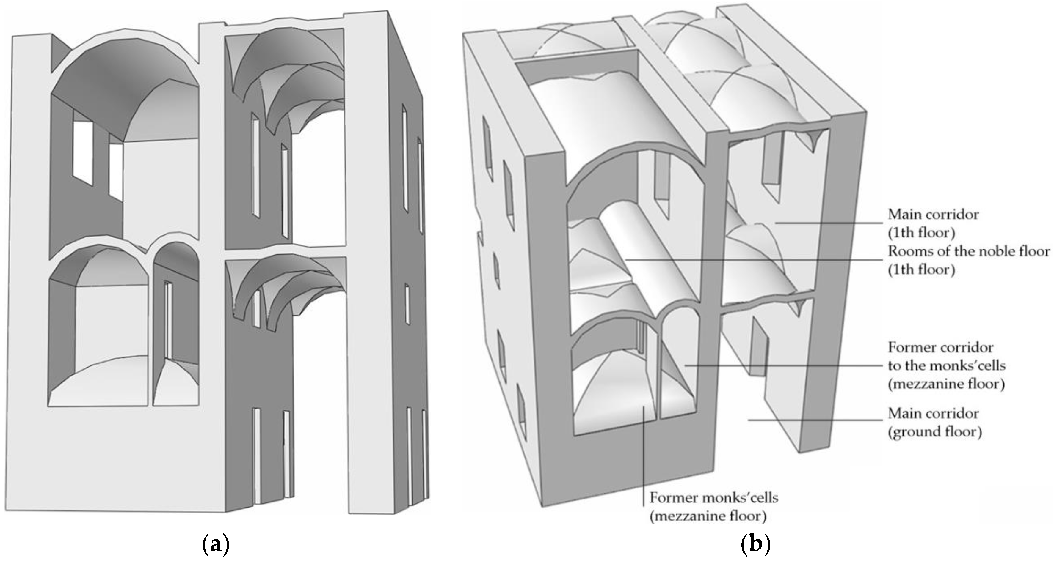
  • Double space volume made by a mezzanine floor, over the ground floor, fitting the height of the side corridor;
  • Presence of bearing walls, built without a direct path to the ground, which transfer the loads directly to the underlying masonry vaults;
  • Inner architectural-structural subdivision of the mezzanine floor in rooms with one or two stories directly neighboring each other;
  • Horizontal structures made of vaults of different typology and geometry.
The circumstance of walls being not vertically continuous to the foundation occurs several times along the elevation of the building; in some cases, they are repeated for overlapping floors, thus increasing the potential seismic risk. The selected span is made up of a barrel vault with cloister heads, belonging to the ground floor, on which rest the walls appointed to transfer the weight of the overhanging rooms. The mezzanine floor has smaller masonry structures in barrel vaults and with cloister heads, and the first floor’s ceiling shows, indeed, all cross vaults; this compartment is flanked by the two-level corridors also covered by cross vaults. All the above mentioned outcomes permitted to qualify in detail the geometrical, constructive and mechanical characteristics of the sub-structure’s elements in order to set up a successive geometrical modeling and the subsequent structural finite element analysis.

3. Geometrical-Mechanical Modeling and Structural Analysis

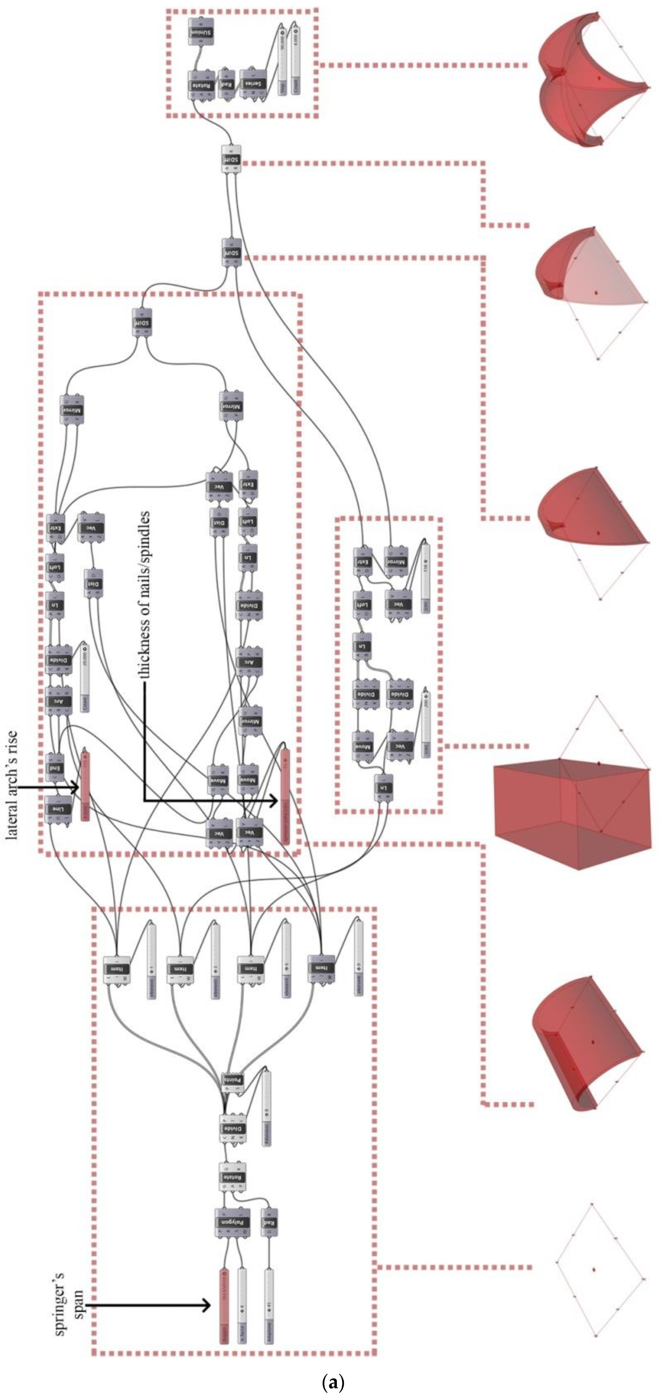
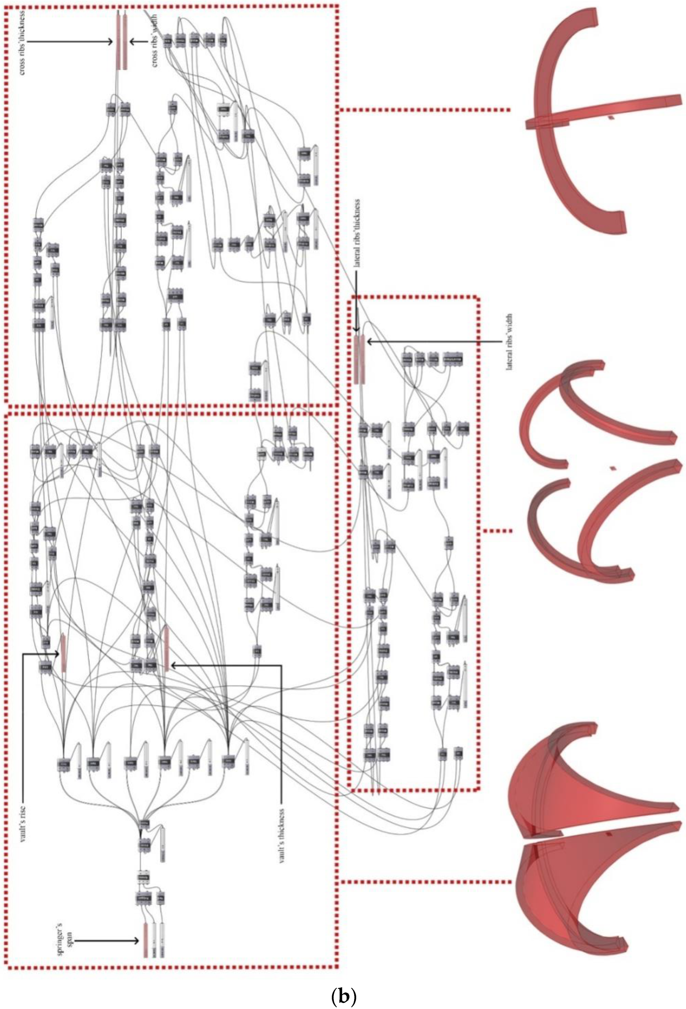
3.1. Parametric Modeling

Although the present contribution is focused on a portion of Murena Palace, the observed different vaults’ typologies, combined with their variety in terms of dimension and thickness of the base elements, makes the 3D modeling of Vanvitelli’s Modulus a quite difficult and long-lasting task. Indeed, the architectural surveys conducted on the selected span allowed to identify the presence of cross vaults, barrel vaults and barrel vaults with cloister heads; later, the investigations and the experimental tests therein conducted permitted to characterize the wide range of thicknesses and the constructive methodologies of those masonry elements. Therefore, with the aim of dealing with the modeling phase as effectively as possible, also from future perspective applications like BIM environment implementations as mentioned before, an innovative parametric modeling has been developed in order to generate vaults’ geometry by union of different complex surfaces [11,12,13]. The proposed procedure, based on a parametric model integrated with measurements and in-situ observations, has been developed in the digital environment Grasshopper®, a Rhinoceros® plug-in [14]. This approach has been conceived in order to analyze the influence of geometrical irregularities on the strength of masonry structures; this aspect has been investigated within some previous contribution in the framework of this ongoing research highlighting how the presence of such topics cannot be neglected since they have a penalizing effect regarding the load bearing capacity of arched masonries [15,16,17,18].
The survey provided information about constructive rules, geometry and connections between different structural elements. Mandatory geometric data for the individual vault, like side arches and ribs, were obtained from the elaboration of such measurements. These data are used as inputs in the parametric algorithm, created to automatically generate the 3D geometry. The final assembly is composed of individual parts (arch, rib, etc.) and nodal zones; this model can be used for successive numerical finite element analysis in order to study the structural response with fidelity to the object or in building information modeling environments [19]. The procedure proved that different 3D models of masonry structures such as cross and barrel vaults (with square, rectangular shape and with or without coves) or ribbed vaults can be created only by changing the values of the input parameters in the model. The programming syntax employed is a visual programming language (VPL) suitable to create algorithms formed by command blocks. Those geometric operators are characterized by an outlet that can be connected to the input ones of the following elements resulting a sort of “blockchain” system in which the alteration of the input data, related to the chosen parameters, entails changes in the following blocks’ features. The 3D model has been designed according to a family of input variables that governs its shape, allowing the rapid generation of various geometries, each one reconfigured in agreement to the changes of the parameters’ values. The implemented algorithm allows the expeditious 3D modeling of different vaults only by the insertion of the data obtained from the structural surveys and experimental investigations as values for the input geometrical and typological parameters [20,21].
On the basis of historical analysis of the literature regarding the construction techniques and the typological characterization of cross vaults, a first phase has been the theorization of a possible parametric transposition of a vault’s geometry for each different type. The cross and the cloister vaults are geometrically defined as curved two-dimensional elements, whose design is based on the principle of the arch and on the parameters that characterize its shape. Those constructive technologies are based on the evolution of a simpler type of vault: the barrel one, consisting of a cylindrical surface which weighs on the lateral bearing walls. A geometric operation suitable to obtain the basic elements constituting the “composed” vaults is to divide the primitive barrel vault with two vertical planes passing through the diagonals of the base edges obtaining four equal two-by-two concave surfaces; these pairs are called masonry “nails” and “spindles”. This is the geometric approach implemented in the following 3D parametric models, Figure 12.
The union of four equal nails results in a square cross vault, likewise the ensemble of four identical spindles produces a cloister vault; in addition, the multiple possibilities of assembly of those elements, which could also have different sizes among themselves, allows to create a variety of vault shapes and typologies. The procedure, expressed in an algorithm, is designed to be entirely governed by only three parameters, which regulate the size and proportions of the vault’s nails and spindles, varying from case to case. Those parameters, pertaining to the base barrel vault, are the distance between springers (span), the thickness and the rise of the edge arches; their range of variability was defined, as already mentioned, from the outcomes of the surveys and experimental investigations. With the aim of obtaining the nail and the spindle, it was necessary to first generate the thick barrel vault from a boolean subtraction of two solid half-cylinders, the largest having a lateral surface coinciding with the extrados of the vault and the smallest representing its intrados. Those solids were previously generated, in turn, through extrusion of the two different parametric half circumferences conveniently modelled as loft surfaces according to the three characteristics described at the beginning of the paragraph; in this passage lies the geometric link that allows the final model to be reconfigured each time. This type of modeling ensures that the aforementioned base arc changes its curvature as a function of the parameter’s variation, e.g., with respect to its rise, passing for instance from a circular arch to a pointed arc or controlling the vault’s thickness changing the distance between the two coplanar external edges. Finally, the two aforementioned basic elements were obtained, one at time according to the desired partition, using Boolean subtractions between the solids resulting from the extrusion of two 2D planar surfaces, orthogonal to the horizontal plane, located on the square base’s diagonals of the barrel vault, Figure 12a. In order to model the wider array of vaults, above all with reference to the cross vaults enhanced with stiffening ribs and lateral arches observable from the main corridors of Murena Palace, the proposed procedure has been improved adding to the previous parameters related to the thickness (often different from that of the nails or spindles forming the vault) and the width of such masonry ribs, ensuring, however, the shape’s relationships with the length of arch’s rise and the size of the polygonal base formed by the spring lines. That device allowed to interpret the diagonal ribs in a parametric way extruding the nail’s limit surfaces and then freeing the thickness value of the latter from the rest of the model, Figure 12b.
On the basis of the types and the geometrical characteristics identified during the surveys for vaults and masonry walls, it was possible, through operations of assembling and merging concerning the different vault’s typological elements previously generated, to realize the final 3D complex model of Vanvitelli’s Modulus, Figure 13.

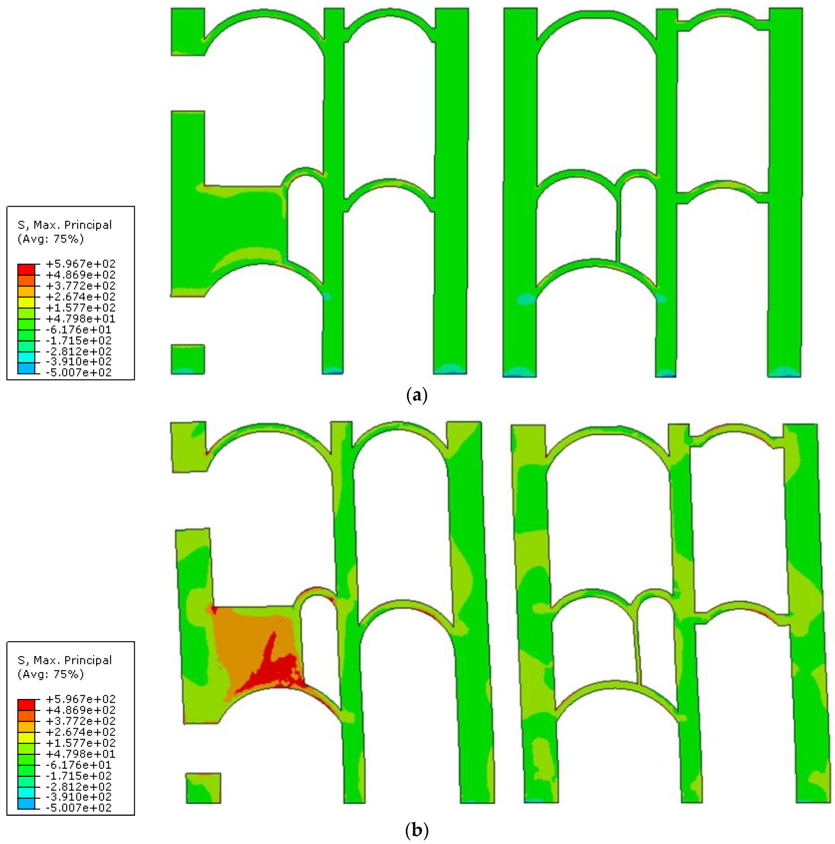
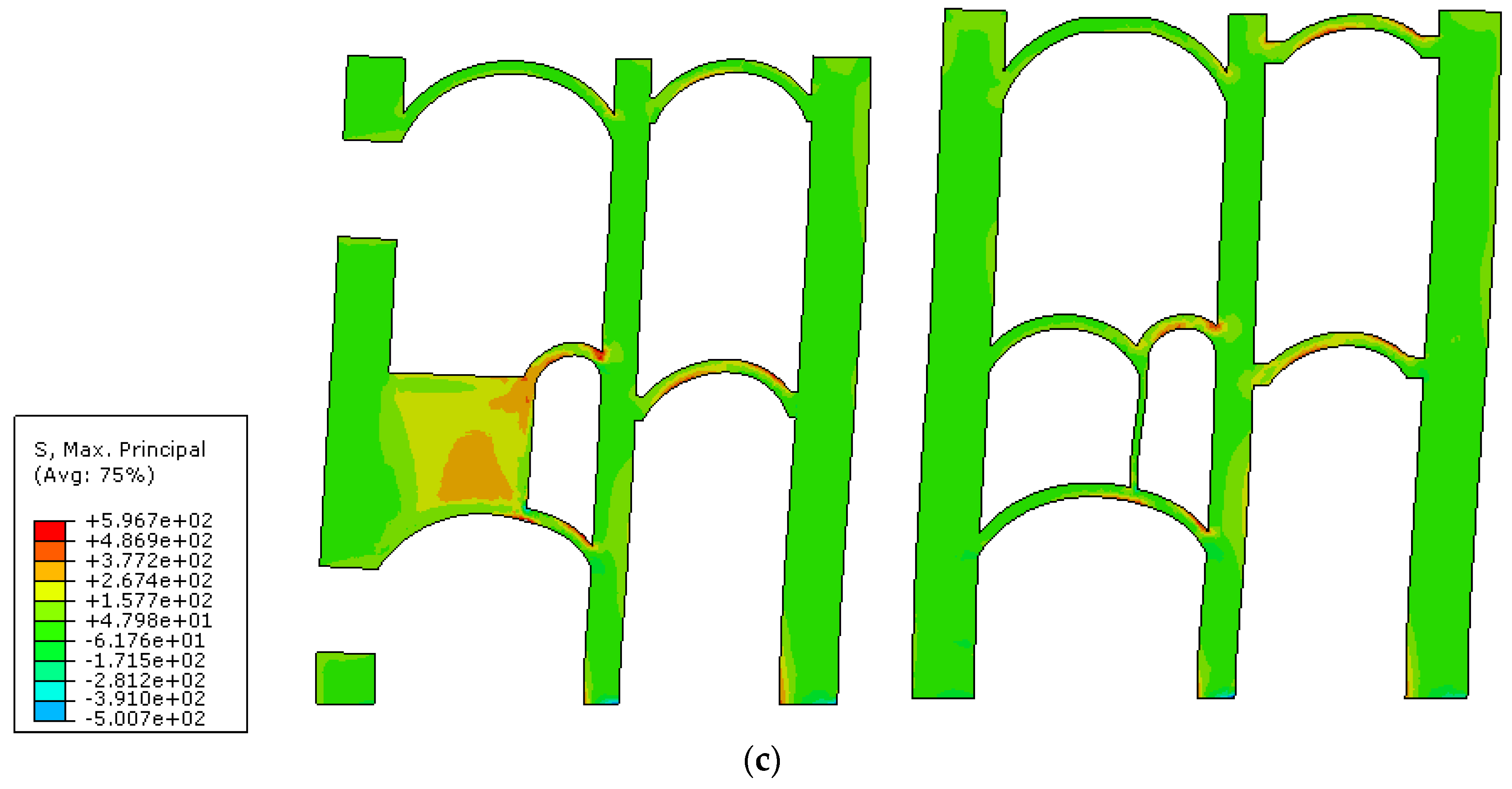
3.2. Structural Analysis

Vanvitelli’s Modulus shows a very interesting behavior from a structural point of view. Going down from above, at the first floor, the impost of the vaults of the corridor, in adherence to the cloister, has a higher quota than the correspondents of the rooms on the external front. This difference in height on the thrusts appears to be absorbed, from masonry structures, as it occurs even more evidently in correspondence of the vaults of the first out ground floor. Furthermore, in correspondence with the mezzanine, the realization of the internal corridor, that served the cells of the friars, means that only part of the floor load is unloaded on the central wall, obviously creating an imbalance between the horizontal thrusts. A portion of the dead load is transferred through internal walls on the underlying vaults, supporting the mezzanine floor, that through their masonry surface transmit to internal wall and external wall. Even in this case, the thrust imbalance is, however, absorbed without the use of tie rods. In addition, as already mentioned, the adequacy of the design of Luigi Vanvitelli is checked by the previously described survey that showed a limited crack pattern.
Nevertheless, to assess the seismic safety of Murena Palace, a deeper knowledge of the structural behavior of Vanvitelli’s construction modulus represents a mandatory requisite. With the aim of a first analysis under static and seismic actions, a numerical model has been implemented by means of the software Abaqus® in a computer aided engineering (CAE) environment [22]. In the framework of a qualitative analysis of the maximum stresses and with the aim to replicate the observed structural damages and the crack patterns, a concrete damaged model calibrated on the actual masonry properties has been used. The geometry of the numerical model has been directly derived from the 3D parametric model previously obtained (Section 3.1), characterized by the material’s mechanical behavior esteemed from the experimental tests’ outcomes and discretized in tetrahedral elements of the C3D10 type. Three loading conditions, one under the dead weights and the other two with the addition of seismic actions in two opposite directions, have been analyzed and finally compared. The intensity of those forces is proportional (15%) to the weight force according to the parameter α. The seismic acceleration (as) has been directly applied to each single meshes’ barycenter in order to define a sort of horizontal gravity force:
as = αg ≃ 1.5 (m/s2)
In the context of the Italian Building Codes [4,5], such an acceleration value corresponds to the inferior limit of the 2nd seismic zone in which Italy’s territory has been subdivided, identifying an area where “strong earthquakes are possible”. Again, referring to the aforementioned code, the numerical analysis permits to conduct a qualitative assessment aimed at the understanding of the structural mechanism involving Vanvitelli’s construction modulus and its seismic safety evaluation. Regarding the constraint conditions in foundations, at this early stage, the nodes on the base of the model have been encastré to the “ground”; in a future perspective, springers, equivalent to the restraints given from the structure of the inferior floors, are thought to be used. Taking into account that Murena Palace was conceived with modular and repetitive functional/structural criteria, the other boundary conditions (aimed at considering the adjacent portions of the building) have been modelled as connecting rods with a horizontal axis. A damage model has been implemented in order to simulate the masonry behavior and its nonlinear response, as usually performed by several research groups, e.g., [23,24,25,26,27,28,29]. Being masonry material characterized by limited tensile strength and high compressive strength, by means of homogenization techniques, the anisotropic characteristics of this heterogeneous material can be modelled like a continuum body having equivalent mechanical behavior, also linked to the specific wall texture [30,31]. In the present paper, the employed elastic-plastic model, damageable for traction stress, is based on the yield function proposed by Lubliner et al. (1989) [32] and subsequently improved by Lee and Fenves (1998) [33] in order to describe the damage evolution of concrete structures. In addition, regarding the masonry compression behavior, the constitutive law’s trend is non-linear already starting from low stress and is therefore characterized by a lowering of the pre-peak branch and, once the value of the compressive strength has been exceeded, from the presence of a falling branch. Therefore, in that limit analysis, the presence of a residual plastic deformation is numerically regulated by means of a progressive flow potential law [34]. In addition, the evolution of a yield (or failure) surface is controlled by two hardening variables linked to the failure mechanisms under tension and compression loading; respectively, we refer to the tensile and to the compressive equivalent plastic strains. It follows that Young’s elastic modulus, E, changes its value according to the stress level and with reference to a yield stress equal to 3.3 × 10² (MPa) arranged to a null initial inelastic strain; such a value for E has been established on the basis of previous experiences, with the aim to be on the safe side, mediating the value from Table 2 with the values, much higher, deriving from the double flat jack tests. Instead, the traction behavior has been characterized defining the value of the tensile fracture stress (σf) as a function associated with the fracture energy, Gf. After the fractures’ occurrence, a linear loss of resistance is attributed to the model where a certain ultimate displacement du = 2 × Gf/σf corresponds to the complete loss of resistance, where the fracture energy equal to 0.1665 (kN/m) has been fixed at a yield stress equal to 333 (kN/m2). The final topic is the definition of the concrete tension damage parameter in relation to cracking strain.
The latter allows to specify the reduction of the stiffness with its increase, since the wreckage of the masonry structures is reached in most cases overcoming the tensile strength, it was considered superfluous to model such behavior for the compression stress. The range of the aforementioned parameter has been fixed between 0 and 0.95 with the upper limit signifying the complete damage of the masonry corresponding to a cracking strain equal to 9 × 10⁻⁴.
Other mechanical masonry properties have been deducted from the experimental tests in relation to the data reliable within the wide scientific literature [35,36,37]; all the parameters and coefficients, calibrated on the safe side, are reported in Table 3.
In the numerical models, in addition to the dead weight of the masonry structures, the contributions of the roof and of the vaults’ filling have been considered. For the roof, according to the surveys and to the Italian Building Code [4], an equivalent load (GKr) has been assumed equal to 10 (kN/m2) applied only on the top terminal surfaces of the bearing masonry walls as a pressure load uniformly distributed. The mass density of the considered filling material amounts to 1300 (Kg/m3) and its thickness, as observed during the experimental tests, is equal to a layer of 10 (cm) gathering a GkF equal to 1.3 (kN/m2) which has been applied as a uniformly distributed pressure on the vaults’ extrados. Regarding the seismic load, the Italian Building Code has been followed [5] with the criteria described by means of the Equation (1). In this static nonlinear analysis, the loading system, representing the inertia forces due to the effects of a horizontal seismic action, has been applied according to a uniform distribution of forces, brought back as a horizontal gravitational load assigned along the building’s height; in accordance with option (a) reported within the second group of the aforementioned code. The same loading system thus defined has been applied both in the direction leaving the courtyard towards the exterior of Murena Palace and in the opposite one. The stress fields, in terms of principal stress with (−) compression and (+) traction, are reported in Figure 14, considering two reference cross sections (see Figure 3 and Figure 4) plotted on the scaled deformed shape.
The behavior of the structure under dead weights reveals a more pronounced deformation of the structure towards the inner courtyard (right side of the cross-section) with concentrations of stresses affecting the upper and lower vaults of the mezzanine floor and also in correspondence of the “in falso wall” towards the inner courtyard. Comparing the tensions of the left part with those concerning the cross vaults of the main corridor on the right it is clear that, from the static point of view, the subdivision of the span made by different masonry vaults contributes to limiting the stress of the structural elements by means of particular re-distribution of the stress, Figure 14a. Taking into account only the dead loads, the formation of any state of masonry damage has not been observed in any portion of the building. Considering the outwards seismic action, an increasing of the stress is observed with its concentration in correspondence of the “in falso wall” mainly concerning the barrel vault with cloister heads, Figure 14b. At the same time, on the vaults, a relevant state of damage is not observable, and the outline of crack patterns engages only the walls and its contact areas with the vault’s extrados.
Between the two analysis procedures, which as mentioned differed uniquely for the force’s directions, is reported only the most noticeable crack pattern deriving from the one under inwards seismic actions. Such analysis reveals a great stress state affecting most of the structural elements belonging to the mezzanine floor according to a different stress configuration, Figure 14c. Unlike the previous analysis, on the vaults a relevant state of damage and the outline of the crack patterns is therefore observable, involving at the intrados the diagonal spindle’s corners and the wall and its contact areas with their extrados, appear to be coherent to the one the one deriving from the damage survey, Figure 15. The masonry vaults are affected by a growth of cylindrical hinges parallel to the lateral walls and situated at the sides of the cornerstone; the circumstances observed also on the ribbed cross vaults of the double spaced main corridor reveal the presence of the so-called “Sabouret cracks”, a type of fissure typical for cross vaults, Figure 15. As mentioned, all the previously described damage modes, resulting from the numerical modeling, are akin to the types of fissures identified during the structural survey; while constituting a widespread state of damage, they do not pose a danger for recurrence and non-significant gravity. Those results are therefore in accordance with the limited risk classification attributed during the aforementioned monitoring’s outcomes and confirms the effectiveness of the structural system devised by Luigi Vanvitelli. Nevertheless, the structural system constituted by the vaults with the presence of load bearing walls system that, vertically located at higher floors, stand on vaults at the first floor, has to be considered; in fact, the inadequate behavior of the system at the first floor can induct a domino collapse.
In the light of the above, the validation of the numerical model has been conducted by means of an implicit process which is founded on the comparison, in terms of damage patterns, between the simulations’ outcomes and the extensive in-situ observations.

4. Conclusions

Stressing the relevance of the cultural heritage buildings’ safeguard, that frequently is put on the line by recurrent earthquakes, it must be attained through the prevention engineering. In the present study, with reference to Murena Palace, the current headquarters of the University of Perugia designed by the prominent Architect Luigi Vanvitelli, the authors have faced such issues focusing on the seismic safety of a peculiar sub-structure observed during the survey within such ancient masonry building, Vanvitelli’s Modulus. A preliminary historical investigation allowed to assert that such peculiarity is coeval with the rest of the building, relating its conception, on the design path of Vanvitelli, to the fulfillment of its end use: this portion of the structure, that manifests itself in elevation as an asymmetrical section which includes the presence of a mezzanine floor and of bearing walls resting directly on the masonry vaults (walls “in falso”), anciently housed a former monastery with the monks’ cells and their corridors. This knowledge has led to deeper investigation of its material and constructive characteristics in the actual state, implementing a damage monitoring system and conducting an experimental test campaign. Such activities highlighted a great variety of bearing masonry vaults in terms of types, size and constructive properties, presenting in addition a limited crack pattern. A new generative parametric model, capable of an expeditious 3D modeling of the wide vaults’ typologies, has been created in order to assembly a complete geometrical model of Vanvitelli’s construction modulus for the subsequent FEM analysis. With the aim to evaluate the structure’s behavior and its robustness, an important feature in order to avoid knock-on collapses, preliminary structural analyses were conducted. The results demonstrated the good functioning of the existing masonries under ordinary conditions, revealing furthermore, under seismic actions, a fascinating mode of stresses’ redistribution within the structural elements composing its double space arrangement. The crack pattern deriving from the seismic simulations confirms the non-immediate risk ranked by the monitoring campaign emphasizing that the seismic safety, especially with reference to the mezzanine floor, must be improved; in fact, the presence of “in falso” bearing masonry walls represents an evident possibility of “domino-type progressive collapse”. Such outcomes push to examine in depth the structural analysis in order to achieve a reinforcement plan compatible with the architectural value of this iconic and strategic building.
In order to increase the robustness of the scheme it is not possible to consider a strengthening intervention on the vaults because this induces demolition of historical overlying floorings or frescos in the intrados. The possibility to use direct strengthening of the “in falso” wall, for example by fiber reinforced cementitious matrix (FRCM), so that, in case of the rupture of the vault, the wall could bear itself by a “wall beam” behavior, is under study for future research.

Author Contributions

In the present contribution, the authors V.G. and R.L. equally contributed on the authorship of the ideational incipit of the research, the various items addressed in the paper. All authors have read and agreed to the published version of the manuscript.

Funding

Authors gratefully acknowledge the support received from the Italian Ministry of University and Research, through the PRIN 2017 funding scheme (Prot. 2017HFPKZY—Modelling of constitutive laws for traditional and innovative building materials).

Acknowledgments

The support received from the University of Perugia and the collaboration of its Technical Office, represented by L. Palma and B. Buonforte, are thanked.

Conflicts of Interest

The authors declare no conflict of interest.

References

  1. Liberotti, R.; Cluni, F.; Gusella, V. Vulnerability and seismic improvement of architectural heritage: The case of Palazzo Murena. Earthq. Struct. 2020, 18, 321–335. [Google Scholar] [CrossRef]
  2. Lagomarsino, S.; Galasco, A.; Penna, A. Nonlinear macro-element dynamic analysis of masonry buildings. In Proceedings of the Thematic Conference on Computational Methods in Structural Dynamics and Earthquake Engineering, Crete, Greece, 13–15 June 2007. [Google Scholar]
  3. Penna, A.; Lagomarsino, S.; Galasco, A. A nonlinear macroelement model for the seismic analysis of masonry buildings. Earthq. Eng. Struct. Dyn. 2013, 43, 159–179. [Google Scholar] [CrossRef]
  4. NTC Decreto Ministeriale 14 Gennaio 2018. Aggiornamento Delle «Norme tecniche Per Le Costruzioni». Supplemento Ordinario Alla “Gazzetta Ufficiale”; N. 42 Del 20 Febbraio 2018—Serie Generale; Ministero Delle Infrastrutture E Dei Trasporti: Roma, Italy, 2018. [Google Scholar]
  5. Circ. No7 Circolare Del Ministero Delle Infrastrutture E Dei Trasporti 21 Gennaio 2019, N. 7. C.S.LL.PP., Istruzioni Per L’Applicazione Dell’ «Aggiornamento Delle “Norme Tecniche Per Le Costruzioni”» Di Cui Al Decreto Ministeriale 17 Gennaio 2018; Supplemento Ordinario Alla “Gazzetta Ufficiale” N. 35 Del 11 Febbraio 2019—Serie Generale; Ministero Delle Infrastrutture E Dei Trasporti: Roma, Italy, 2019. [Google Scholar]
  6. D’Ayala, D.; Speranza, E. Definition of collapse mechanisms and seismic vulnerability of historic masonry buildings. Earthq. Spectra 2003, 19, 479–509. [Google Scholar] [CrossRef]
  7. Valente, M.; Milani, G. Damage assessment and partial failure mechanisms activation of historical masonry churches under seismic actions: Three case studies in Mantua. Eng. Fail. Anal. 2018, 92, 495–519. [Google Scholar] [CrossRef]
  8. Sorignani, C. UNI|TECA Progetto Architettonico di Trasformazione in Gipsoteca Dell’edificio Sede Dell’ufficio Economato Dell’università Degli Studi di Perugia. Master’s Thesis, University of Perugia, Perugia, Italy, 2018. [Google Scholar]
  9. Cavalagli, N.; Gusella, V.; Severini, L. The safety of masonry arches with uncertain geometry. Comput. Struct. 2017, 188, 17–31. [Google Scholar] [CrossRef]
  10. Gioffrè, M.; Gusella, V.; Cluni, F. Performance evaluation of monumental bridges: Testing and monitoring ‘Ponte delle Torri’ in Spoleto. Struct. Infrastruct. Eng. 2008, 4, 95–106. [Google Scholar] [CrossRef]
  11. Cavalagli, N.; Cluni, F.; Gusella, V. Failure surface of quasi-periodic masonry by means of statistically equivalent periodic unit cell approach. Meccanica 2017, 53, 1719–1736. [Google Scholar] [CrossRef] [Green Version]
  12. Liberotti, R. Modellazione Parametrica Geometrico-Strutturale di Volte a Crociera in Muratura. Master’s Thesis, University of Perugia, Perugia, Italy, 2018. [Google Scholar]
  13. Issa, R.R.A. Advanced construction information modeling: Technology integration and education. In Haptics: Science, Technology, Applications; Springer Science and Business Media LLC: Berlin/Heidelberg, Germany, 2018; pp. 311–335. [Google Scholar]
  14. Melachos, F.; Florio, W.; Rossato, L.; Balzani, M. Parametrical analysis and digital fabrication of thin shell structures: The impact of construction technique on the resulting geometry of the gaussian vaults of eladio dieste. ISPRS Int. Arch. Photogramm. Remote. Sens. Spat. Inf. Sci. 2019, 42, 479–485. [Google Scholar] [CrossRef] [Green Version]
  15. Cavalagli, N.; Gusella, V.; Severini, L. Lateral loads carrying capacity and minimum thickness of circular and pointed masonry arches. Int. J. Mech. Sci. 2016, 115, 645–656. [Google Scholar] [CrossRef]
  16. Cavalagli, N.; Gusella, V.; Liberotti, R. The role of shape irregularities on the lateral loads bearing capacity of circular masonry arches. In Proceedings of the XXIV AIMETA Conference 2019, Rome, Italy, 15–19 September 2019; pp. 2069–2081. [Google Scholar]
  17. Severini, L.; Cavalagli, N.; DeJong, M.; Gusella, V. Dynamic response of masonry arch with geometrical irregularities subjected to a pulse-type ground motion. Nonlinear Dyn. 2017, 91, 609–624. [Google Scholar] [CrossRef] [Green Version]
  18. Zampieri, P.; Cavalagli, N.; Gusella, V.; Pellegrino, C. Collapse displacements of masonry arch with geometrical uncertainties on spreading supports. Comput. Struct. 2018, 208, 118–129. [Google Scholar] [CrossRef] [Green Version]
  19. Angjeliu, G.; Cardani, G.; Coronelli, D. A parametric model for ribbed masonry vaults. Autom. Constr. 2019, 105, 102785. [Google Scholar] [CrossRef]
  20. Di Paola, F.; Mercurio, A. Design and digital fabrication of a parametric joint for bamboo sustainable structures. Adv. Intell. Syst. Comput. 2019, 975, 180–189. [Google Scholar] [CrossRef]
  21. Peng, T.; Wang, X.; Shi, X. Generative design method of the facade of traditional architecture and settlement based on knowledge discovery and digital generation: A case study of Gunanjie Street in China. Int. J. Arch. Herit. 2018, 13, 679–690. [Google Scholar] [CrossRef]
  22. Dassault Systèmes. Abaqus 6.13 Abaqus/CAE User’s Guide. Available online: http://130.149.89.49:2080/v6.13/pdf_books/CAE.pdf (accessed on 5 July 2020).
  23. Betti, M.; Galano, L. Seismic analysis of historic masonry buildings: The vicarious palace in Pescia (Italy). Buildings 2012, 2, 63–82. [Google Scholar] [CrossRef]
  24. Ceroni, F.; Pecce, M.R.; Sica, S.; Garofano, A. Assessment of seismic vulnerability of a historical masonry building. Buildings 2012, 2, 332–358. [Google Scholar] [CrossRef]
  25. Cardani, G.; Belluco, P. Reducing the loss of built heritage in seismic areas. Buildings 2018, 8, 19. [Google Scholar] [CrossRef] [Green Version]
  26. Creazza, G.; Matteazzi, R.; Saetta, A.; Vitaliani, R. Analyses of masonry vaults: A macro approach based on three-dimensional damage model. J. Struct. Eng. 2002, 128, 646–654. [Google Scholar] [CrossRef]
  27. Gaetani, A.; Lourenço, P.B.; Monti, G.; Milani, G. A parametric investigation on the seismic capacity of masonry cross vaults. Eng. Struct. 2017, 148, 686–703. [Google Scholar] [CrossRef] [Green Version]
  28. Coccia, S.; Como, M. Minimum thrust of rounded cross vaults. Int. J. Arch. Herit. 2014, 9, 468–484. [Google Scholar] [CrossRef]
  29. Castori, G.; Borri, A.; De Maria, A.; Corradi, M.; Sisti, R. Seismic vulnerability assessment of a monumental masonry building. Eng. Struct. 2017, 136, 454–465. [Google Scholar] [CrossRef]
  30. Gusella, V.; Cluni, F. Random field and homogenization for masonry with nonperiodic microstructure. J. Mech. Mater. Struct. 2006, 1, 357–386. [Google Scholar] [CrossRef] [Green Version]
  31. Cavalagli, N.; Cluni, F.; Gusella, V. Strength domain of non-periodic masonry by homogenization in generalized plane state. Eur. J. Mech. A/Solids 2011, 30, 113–126. [Google Scholar] [CrossRef]
  32. Lubliner, J.; Oliver, J.; Oller, S.; Oñate, E. A plastic-damage model for concrete. Int. J. Solids Struct. 1989, 25, 299–326. [Google Scholar] [CrossRef]
  33. Lee, J.; Fenves, G.L. Plastic-damage model for cyclic loading of concrete structures. J. Eng. Mech. 1998, 124, 892–900. [Google Scholar] [CrossRef]
  34. Krenk, S. Friction, dilation, and plastic flow potential. Phys. Dry Granul. Media 1998, 18, 255–260. [Google Scholar] [CrossRef]
  35. Cavalagli, N.; Gusella, V. Dome of the basilica of santa maria degli angeli in assisi: Static and dynamic assessment. Int. J. Arch. Herit. 2014, 9, 157–175. [Google Scholar] [CrossRef]
  36. Cavalagli, N.; Gusella, V. Structural investigation of 18th-century ogival masonry domes: From Carlo Fontana to Bernardo Vittone. Int. J. Arch. Herit. 2014, 9, 265–276. [Google Scholar] [CrossRef]
  37. Clementi, F.; Ferrante, A.; Giordano, E.; Dubois, F.; Lenci, S. Damage assessment of ancient masonry churches stroked by the Central Italy earthquakes of 2016 by the non-smooth contact dynamics method. Bull. Earthq. Eng. 2019, 18, 455–486. [Google Scholar] [CrossRef] [Green Version]
Figure 1. Current view of complex of Murena Palace in Perugia, Italy. Reworked from Google Maps, cartographic data (2020).
Buildings 10 00164 g001
Figure 2. Plan of the architectural complex: (1) Murena Palace; (2) University Church; (3) Ex-Accountancy Office.
Buildings 10 00164 g002
Figure 3. Survey of plan of the first floor completely out ground (level of the Church of Montemorcino Nuovo; h = 0.0 m): red lines—main lesions on the vaults, blue lines—steel tires installed after the 1997 earthquake. Location of the monitoring instruments: F1–F17 crack-meters, I1–I5 inclinometers, V4 videoendoscopy. The span selected for the following FEM is highlighted in red.
Buildings 10 00164 g003
Figure 4. Survey of plan of the mezzanine floor (h = 4.7 m). In red lines, the main lesions on the vaults are reported. The span selected for the following FEM is highlighted in red. The location of the performed videoendoscopies is reported (V5, V6).
Buildings 10 00164 g004
Figure 5. Front of Murena Palace.
Buildings 10 00164 g005
Figure 6. Section of Murena Palace.
Buildings 10 00164 g006
Figure 7. Re-elaboration of the original design drawings of the monastery of Monte Morcino Nuovo from Luigi Vanvitelli and the wall of the camp of the St. Benedict’s nuns. On the right, in light red, the cross-section of Vanvitelli’s Modulus. Extracted from the researches of C. Sorignani (State Archives of Perugia, 1739) [8].
Buildings 10 00164 g007
Figure 8. Cross section of the Royal Palace of Caserta. In red are highlighted the “in falso” walls and some of the double-space levels (1700–1773). Re-elaboration from De Agostini Picture Library, L. Romano at www.gettyimages.it.
Buildings 10 00164 g008
Figure 9. Survey of the ground floor span of Vanvitelli’s Modulus: (a) The plan: in light red, the bulk of the overhead in falso walls; (b) an extract from a generic cross section, where: lesions on the structural elements (L), masonry walls (M), pavings (P), masonry vaults (V), videoendoscopies (VE).
Buildings 10 00164 g009
Figure 10. Videoendoscopy V5-from ceiling: (a) Image at 11 cm from the beginning of the hole reveals filling in unbound material; (b) Image at 5 cm from the beginning of the hole presents brick and mortar elements.
Buildings 10 00164 g010
Figure 11. Some results of the monitoring systems (the location of the instruments is shown in Figure 3). The recordings of the crack-meter F11 are marked in red in relation to that of the thermo-hygrometer in pale blue: displacement (-) stands for crack’s closure; displacement (+) coincides with an opening of the cracks.
Buildings 10 00164 g011
Figure 12. Generative algorithms for vaults, example of a cross vault generation; the geometrical parameters are shown in red and commands’ groups are linked with the associated 3D modeling outcomes: (a) Preliminary algorithm for barrel, cross and cloister vaults with regular or irregular shape and mixed features; (b) Refined algorithm adding the side and diagonal stiffening ribs according to vault’s type.
Buildings 10 00164 g012aBuildings 10 00164 g012b
Figure 13. Views of the 3D geometry of Vanvitelli’s Modulus: (a) North–South direction; (b) Upper view.
Buildings 10 00164 g013
Figure 14. Plot extracted from the FEM. Stress gradient in relation respectively to the cross-sections A-A’ and B-B’ placed as in Figure 3 and Figure 4: (a) dead weight; (b) outwards seismic action; (c) inwards seismic action. The stresses are between 5.9 × 10² and –5 × 10² (kPa).
Buildings 10 00164 g014aBuildings 10 00164 g014b
Figure 15. Comparison between the damage survey and the crack pattern at the vaults’ intrados coming from the finite element analysisfor inwards seismic action: (a) ground floor; (b) mezzanine floor. The damages are between 0 and 1.6.
Buildings 10 00164 g015
Table 1. Extract of the Parametric Catalog of Italian Earthquakes for the Perugia district from the 18th century to the present day. The information reported for each seismic event are: Intensity expressed in the Mercalli scale; Io—Epicentral intensity; Mw—Moment magnitude calculated on the entire seismograms starting from the estimate of the geometric feature of the fault (for further details please check the I.N.G.V web site).
Intensitymm/dd/yyyyEpicentral AreaIoMw
610/11/1791Sellano85.57
702/12/1854Cannara85.57
309/15/1878Montefalco85.46
304/14/1918Monti Martani64.48
509/19/1979Norcia8–95.83
504/29/1984Gubbio75.72
5–609/26/1997Colfiorito8–95.97
Table 2. Range of values of the mechanic parameters related to the walls identified for the analysis, extracted from Table C8.5.I of the Circ. No 7/2019 for masonry in split stone with good texture (MS) and masonry in solid bricks and lime mortar (MB): fm—compression strength; τ0—shear strength in absence of normal stresses; E—modulus of elasticity; G—tangential elasticity modulus; w—specific weight.
Wall Typefm (MPa)τ0 (MPa)E (MPa)G (MPa)w (kN/m3)
MSmin2.6 × 1045.6 × 102150050021
max3.8 × 1047.4 × 1021980660
MBmin2406120040018
max4009.21800600
Table 3. Data defining the mechanical behavior and the damage model: E—Young’s modulus; ν—Poissons’ratio; ρ—Mass Density; Φ —Dilatation angle in the p–q (pressure invariant-stress meridian) plane; ϵ—eccentricity that defines the rate at which the hyperbolic flow potential approaches its asymptote; fb0/fc0—ratio of initial compressive yield stress to initial uniaxial compressive yield stress; Kc—ratio of the second stress invariant on the tensile meridian to that on the compressive meridian; μ—viscosity parameter representing the relaxation time of the system used for the visco-plastic regularization of the concrete constitutive equations (for more details see the Abaqus manual [22]).
E (MPa)νρ (kN/m4s2)Φ (°)ϵfb0/fc0Kcμ (s)
33300.342100.10.160.66710−4

