Article

Experimental and Numerical Study of Behaviour of Reinforced Masonry Walls with NSM CFRP Strips Subjected to Combined Loads

by
Houria Hernoune
1,
Benchaa Benabed
2,*,
Antonios Kanellopoulos
3,*,
Alaa Hussein Al-Zuhairi
4 and
Abdelhamid Guettala
5
1
Department of Civil Engineering, University of Yahia Fares, Medea 2600, Algeria
2
Laboratory Civil engineering, University of Amar Telidji, Laghouat 03000, Algeria
3
Centre for Engineering Research, School of Engineering and Computer Science, University of Hertfordshire, Hatfield AL10 9AB, UK
4
Department of Civil Engineering, University of Baghdad, Baghdad 10071, Iraq
5
Department of Civil Engineering, University of Mohamed Khider, Biskra 07000, Algeria
*
Authors to whom correspondence should be addressed.
Buildings 2020, 10(6), 103; https://doi.org/10.3390/buildings10060103
Submission received: 23 April 2020 / Revised: 19 May 2020 / Accepted: 26 May 2020 / Published: 31 May 2020

Abstract

:
Near surface mounted (NSM) carbon fibers reinforced polymer (CFRP) reinforcement is one of the techniques for reinforcing masonry structures and is considered to provide significant advantages. This paper is composed of two parts. The first part presents the experimental study of brick masonry walls reinforced with NSM CFRP strips under combined shear-compression loads. Masonry walls have been tested under vertical compression, with different bed joint orientations 90° and 45° relative to the loading direction. Different reinforcement orientations were used including vertical, horizontal, and a combination of both sides of the wall. The second part of this paper comprises a numerical analysis of unreinforced brick masonry (URM) walls using the detailed micro-modelling approach (DMM) by means of ABAQUS software. In this analysis, the non-linearity behavior of brick and mortar was simulated using the concrete damaged plasticity (CDP) constitutive laws. The results proved that the application of the NSM-CFRP strips on the masonry wall influences significantly strength, ductility, and post-peak behavior, as well as changing the failure modes. The adopted DMM model provides a good interface to predict the post peak behavior and failure mode of unreinforced brick masonry walls.

1. Introduction

Masonry is an anisotropic material, considering only plane homogenous stress states, it is characterized by many different failure modes and performances [1,2]. This property strongly affects the response of masonry wall subjected to in-plane seismic forces. From the uniaxial compressive load tests on masonry panels in which bed joints are oriented at different angles to the direction of the applied load, the combined shear–compression behavior of masonry have also been reported by some researchers [3,4]. The failure of masonry under uniaxial compression combined shear and compression has been extensively studied in the past by many researches [5]. These failures represent particular points on the general failure surface. The influence of the orientation of the applied stresses to the joints has also been discussed in the literature concerning shear wall behavior [6].
Around the world, there are many old unreinforced masonry (URM) structures such as historical cultural monuments and bridges. Many of these structures are exposed either to excessive loads or to unpredicted loading scenarios such as earthquakes [7,8]. Different techniques have been developed to prolong the life of these structures. Several of these reinforcement systems include the application of fiber-reinforced polymer (FRP) composites to strengthen masonry structures. Using FRPs offers several advantages such as increasing strength and ductility of walls subjected to either out-of- or in- plane lateral loading. El-Gawady et al. [9] and Korany et al. [10] have reviewed the techniques of retrofit/repair masonry walls with FRP composites. Such composites offer the possibility of either adhering them on the outside surface (externally bonded—EB) or inserting them inside a groove of a masonry element by the NSM technique. Seracino and Wylie [11] recommended that the placement of NSM FRP in the vertical and/or horizontal direction depends on the loading and boundary conditions of the wall. Petersen et al. [12] carried out tests to study the bond behavior of clay brick masonry prisms reinforced with vertical strips and horizontal strips (CFRP perpendicular and parallel to bed joints). They applied CFRP strips with a rectangular form to maximize the confinement from the surrounding concrete. Tests noted that the principal failure mode was the debonding of CFRP from the masonry wall for both orientations of CFRP strips. For solid bricks with vertical NSM-CFRP strips inserted into brick only, they found that the bond strength decreased by a rate of 8%. If the vertical NSM-CFRP strips passed through mortar head joint, a reduction in the bond strength of 11% was observed. Further decrease (31%) in bond strength was recorded when the FRP was aligned horizontally. A number of researchers investigated the effect of single-sided (or non-symmetric) strengthening. Valluzzi et al. [13] examined a series of unreinforced brick masonry walls strengthened by different FRP composites such as CFRP, GFRP, and AFRP fibers of different forms and subjected to a diagonal compression test. The results showed that the application of FRP at one side of the wall produces a significant failure mode of out-of-plane deformation. The magnitude of this failure intensified by the limited restraint at the bottom and top corners of the wall. Petersen et al. [14] investigated the in-plane shear behavior of masonry walls reinforced with NSM CFRP using different reinforcement orientations such as vertical strips, horizontal strips, and a mixture of both. It was observed that the application of vertical NSM-FRP strips applied to both front and backsides of the masonry walls led to 46% improvement of the load capacity. In addition, when both horizontal and vertical NSM strips were used, the horizontal strips prevented the opening of diagonal cracks while the vertical strips prevented the sliding failure. Dizhur et al. [15] performed several tests with various NSM-CRFP retrofitting and repair schemes on URM walls loaded in diagonal compression. They reported that retrofitted walls showed an increase in the maximum shear strength ranging from 1.3 to 2.6 times. For repaired walls, the increase ranging from 1.3 to 3.7 times compared to the masonry wall. Furthermore, they observed a considerable increase in ductility of 2.6 times for walls retrofitted on one side and 25.5 times for the walls retrofitted on both sides. The effect of different parameters including the groove dimensions, the dimensions of CFRP, shape of CFRP, and the adhesive type in NSM-strengthened brick masonry has been investigated by Maljaee et al. [16]. Existing experimental and analytical research has led to two major approaches for masonry modeling, namely heterogeneous and homogeneous modeling. In the former, the brick units and joint mortar are considered separately. While in the latter, the brick units, joint mortar and interfaces between them are assumed by an isotropic or anisotropic composite material. According to Lourenco [17], there are two main modelling approaches macro-modelling and micro-modelling. The micro-modeling can be divided into two techniques: detailed micro-modeling and simplified micro modeling [18,19]. In the detailed micro-modeling, each component (units, mortar) is modeled separately with unit-mortar interface. The masonry units and mortar are modeled with true thickness, whereas zero thickness is attributed to unit-mortar interfaces. The units and mortar are modelled as continuous elements and unit-mortar interfaces are modelled as discontinuous elements.
To understand the behavior of masonry, the literature has focused on the importance of including all rupture mechanisms of the masonry in the modeling in terms of ultimate load and ductility on all the damage, which is normally concentrated at the mortar interface [20,21]. Modeling the complex behavior of masonry is a difficult task in the finite element analysis of civil engineering structures. Only tensile brick rupture is often considered in microscopic models, relying mainly on linear elastic behavior. The authors took that model to introduce the mortar’s post-peak softening behavior.
There is no published literature on reinforced masonry walls that discusses the shear test when the loading is applied by means of compression force only. In such a scenario, the bed joints are at an angle with the loading direction. However, the effect of combined stresses to the strength and deformation of this reinforced masonry system is not widely available in the literature. With a view to bridging this gap, experimental studies on the behavior including ductility and failure mode of NSM CFRP reinforced brick masonry wall under combined shear–compression were carried out.
This paper presents masonry panels with two bed joint orientations that were constructed and tested under vertical compression to generate a wide range of compression to shear ratios from one to infinity at each of the bed joints of the panels. The effect of the type of joint mortar, the efficiency of NSM-FRP technique and the position of the CFRP strips for improving the shear strength and ductility of the reinforced wall are discussed in detail. An analytical approach is developed to simulate the behavior of unreinforced masonry walls under combined load, using the detailed micro-modelling approach (DMM) implemented in ABAQUS. The material nonlinearities of units, mortar and unit-mortar interfaces in both tensile and compression regimes have been assigned. In this analysis, the non-linearities behavior of brick and mortar was simulated using the Concrete Damaged Plasticity (CDP) constitutive laws.

2. Materials and Methods

2.1. Materials

2.1.1. Brick Units

To evaluate the compressive strength and elastic modulus of masonry units, nine specimens of perforated clay bricks with dimensions 220 mm long, 105 mm wide and 55 mm high were tested according to EN 771-1 [22] (Figure 1). The compressive strength and elastic modulus values are presented in Table 1.

2.1.2. Cement-Lime Mortar

Two types of mortar consisting of cement, lime and sand were prepared. The proportions of cement, lime and sand were 1:1:3 and 1:1:5 respectively. Both types of mortar had a water to cement ratio of 0.5. Flexural and compressive resistance were determined in accordance with EN1015-11 [23] and the results are presented in Table 1.

2.1.3. Composite Materials (CFRP)
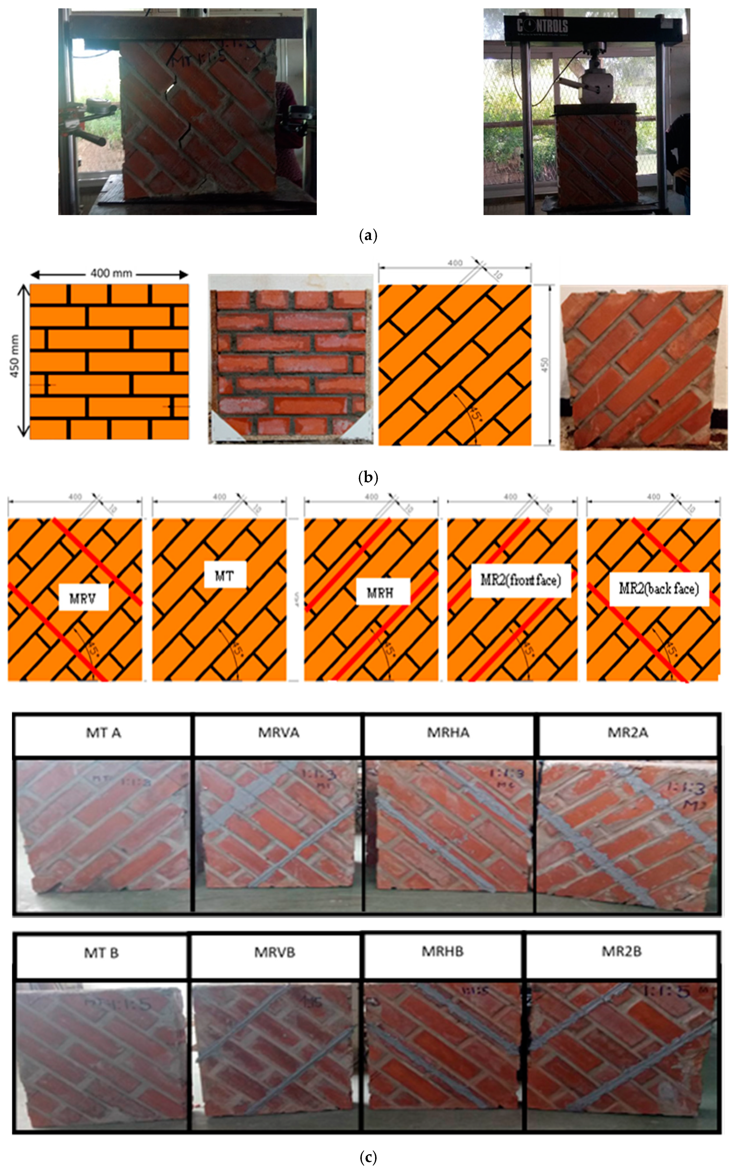
The CFRP strip has an elastic modulus equal to approximately 165,000 MPa, and rupture strain equal to 1.7%. The properties of composite materials of CFRP applied in the reinforcement of masonry wall panels are presented in Table 2.

2.2. Methods

The masonry panels were categorized into two series. In the first series, the compressive behavior is defined on a panel subjected to uniaxial compression perpendicular to bed joint θ = 90° with two different types of mortar (A, B). In the second series, a combined shear–compression behavior of un-strengthened and strengthened masonry (θ = 45°) has been studied using the same types of mortar.
The experimental program consisted of a total of 20 tests, 6 un-strengthened masonry panels as control specimens (MCA, MCB) with θ = 90° and (MTA, MTB) with θ = 45°, and 12 strengthened panels. Four of the strengthened panels have only horizontal NSM CFRP strips (parallel to bed joints) with both types of mortar (MRHA, MRHB), and four having only vertical NSM CFRP strips (perpendicular to bed joints) with both types of mortar (MRVA, MRVB). The remaining four panels were reinforced with two vertical strips on one side of the panels and two horizontal strips on the other side MR2A and MR2B (Table 3). Full view of walls specimens is shown in Figure 2.
The test specimens were made according to RILEM technical recommendation for testing small walls under compression [24]. The specimen was a masonry panel made of perforated bricks with dimensions 220 × 105 × 55 mm. The specimens were tested under uniaxial loading with different orientations of the bed joints. The varied inclinations were 90° and 45°.
The specimens were aligned between the platens of the testing machine carefully to avoid eccentricity in loading. Furthermore, to avoid any contact between the steel plates and the surfaces of the masonry specimen, support plates were placed to ensure a better distribution of forces without any eccentricity. Full contact between upper and lower surfaces of specimens and surfaces of steel plates of the testing machine was assured. A computer-controlled servo hydraulic frame with a capacity of 160 kN was used to carry out the tests. The displacement measurements were carried out using comparators that have been installed on both sides of the panel. All test data were collected by a data acquisition system.
The tests were performed under displacement control in order to obtain the complete stress–strain curve of the panels. All tested wall panels were of similar dimensions in order to allow direct comparison of their failure loads. The FRP reinforcement was glued, using two-part epoxy adhesive, into rectangular grooves cut in the surface of the masonry with a circular saw. Full view of the fabrication of specimens and installation of CFRP is shown in Figure 3.

3. Results and Discussion

3.1. Unreinforced Masonry Panels Subjected to Uniaxial Compression

3.1.1. Unreinforced Masonry Panels Subjected to Uniaxial Compression θ = 90° (MCA, MCB)

Panels subjected to uniaxial compression perpendicular to bed joint (θ = 90°) collapsed due to vertical cracking at the level of face shells of the masonry wall (Figure 4). The face-shell cracking occurred at a load near to 95% of the ultimate load. The vertical cracks on the face shell perpendicular to the joints can be due to different levels of lateral expansion of the units and mortar under compressive stresses, which causes tensile splitting of brick and perpendicular joints. The splitting cracks result in two face shells that deform individually and become more fragile. This failure pattern has been reported by other researchers [25,26]. A reduction of mortar strength with an increase in the proportion of sand in mortar is observed, whereas a slight increase was observed in the value of compressive strength for masonry panels MCB compared to masonry panels MCA (2.23 MPa and 2.16 MPa respectively). This indicates the insignificant effect of mortar strength on the compressive strength of the masonry wall (3%). The elastic modulus of the masonry wall is calculated as the second modulus of the stress–strain curve obtained during an experimental prism test within stress levels of 0.05 and 0.33 times σm.
The values of Young’s modulus of masonry panels obtained for each wall MC are summarized in Table 4. The results show that the value of the modulus of linear deformation is low compared with the correlations between E and fc provided by the codes: E/fc = 1000 as in CSA 2004 [27] and E/fc = 850 in EN 1052-1 [28]. Most of the formulae that calculate the elastic modulus of the masonry give a value greater than the experimental value. Augenti et al. [29] found that the elastic modulus varies between 250–1100 times the compressive strength of masonry. They proposed an average value of Young’s modulus equal to 550 times the compressive strength. The results obtained show that the measured values are close to those found by FEMA306 [30], which propose E, mac ≈ 550σc, mac, where, σc, mac is the compressive strength of masonry units.
Venkatarama Reddy and Uday Vyas [31] investigated the influence of bond strength on stress–strain characteristics of masonry employing a cement–lime mortar and soil–cement blocks. These studies show that when the masonry unit is stiffer than that of mortar (Eblock/Emortar ratio greater than one), the masonry compressive strength is not sensitive to bond strength variation and the modulus decreases with an increase in bond strength. In addition, the modulus of masonry is less than that of the block and the mortar when Eunit/Emortar ratio is less than one. However, the results of the present study indicated that the modulus of masonry is less than that of the block and mortar, although the Eunit/Emortar ratio is greater than one (Table 5).

3.1.2. Unreinforced Masonry Wall Subjected to Uniaxial Compression with θ = 45°

The combined shear and normal stresses play a significant role in the failure modes and deformation on the levels of the bed and head joints. For a uniaxial state of stress that is inclined relative to the x-axis at an angle θ, if angle θ varies, the normal stress σ n decreases and shear stress τn increases on an inclined plane. The maximum shear stress of magnitude τ m a x occurs on the planes oriented at 45° to the x-axis. Using equilibrium Equations (1)–(3) along the bed and perpendicular joints respectively, the applied vertical compressive stress σ y can be converted to compressive and shear stresses (σn, τnp) and (σp, τnp). The three linear strains (εx, εy, ε45) can be used to determine the normal and parallel strains (εn, εp) and the shear strain (γnp) on the plane of the specimen using the strain transformation equations [32], in which θ is the angle of bed joint to the x axis (Figure 5).
σ n = σ y sin 2 θ
σ p = σ y cos 2 θ
τ n p = σ y sin θ cos θ
In case θ equals 45°, the shear stress (τ) equals the normal stress ( σ n ) on the sliding surface.
The shear modulus (G) is calculated using:
τ = G   γ
The shear angle γ is calculated following:
γ = a r c t a n g Δ h × s i n ( α ) h × sin ( α )
In wall panels MTA and MTB, cracking occurred primarily in a diagonal through the mortar joints followed by a rapid reduction in load capacity. With load increasing, the wall exhibited a gradual increase in the width of a predominately diagonally oriented crack, followed by sliding along the formed cracks (Figure 6a). With further increase in load, multiple cracks were observed in the panel MTB before failure as shown in Figure 6b. The ultimate loads of MTA and MTB panels were measured as 69.2 kN and 91.0 kN, respectively (Table 6). The response of the tested unreinforced wall panels (MTA and MTB) to shear stress-strain is summarized in Figure 6c. The shear strength of the masonry panel constructed with mortar A was lower than the shear strength of the corresponding masonry panel constructed with mortar B. It is observed that both MTA and MTB wall panels presented an approximately linear shear stress–strain relationship before cracking, followed by rapid degradation of shear strength once cracking had propagated, followed by a slight increase in shear strength and deformation before rupture (Figure 6c).
The wall panels tested with an orientation of bed joint by 45° failed at lower load compared to the wall panel tested when its bed joint makes 90° with loading axis. The same observation was found for the Young’s modulus. For these orientations, the load bearing capacity was affected by the brick strength and the shear bond characteristics of the joints. Since the masonry joints act as planes of weakness in the traditional masonry, they tend to degrade the orthotropic behavior under different orientations of bed joints to the direction of loading. The ratio of the compressive strength at 45° (f45°) to the compressive strength perpendicular to the bed joint (f90°), was found at a range of 0.38 to 0.48, which is highly orthotropic. This is what led to a reduction of strength by up to 62%. Consequently, the failure load of the unreinforced wall panels was highly dependent on the bed joint orientation. As the orientation changes from 90° to 45°, the average strength value reduced from 2.22 MPa to 1.08 MPa for masonry panels MTB and from 2.16 MPa to 0.82 MPa for masonry panels MTA, which represented about 40% of the strength reduction. The shear modules of wall panel A and wall panel B were determined as 125 MPa and 137.3 MPa, respectively.

3.2. Reinforced Masonry Walls Subjected to Uniaxial Compression with θ = 45°

The reinforcement schemes used for the strengthening of panels are summarized in Figure 1b:
  • Panels MRVA and MRVB were reinforced with two vertical strips on one side;
  • Panels MRHA and MRHB were reinforced with two horizontal strips on one side;
  • Panels MR2A and MR2B were reinforced with two vertical strips on one side and two horizontal strips on the other side. The distance between the staggered vertical reinforcement was 135 mm.
The criteria established by Park [32] were used to calculate the displacement ductility factor of all tested panels. The displacement ductility factor ( μ ) is defined as the ratio between the ultimate displacement to the yield displacement:
μ = δ u δ y
δ u = displacement at ultimate load
δ y = displacement at the load causing yield condition
In unreinforced walls, the tensile stress causes an appearance of cracks leading to a complete destruction. However, in the case of walls reinforced with CFRP strips, the tensile stresses are transferred to these strips resulting in the masonry wall being greatly reduced in stress. As the load increases, the maximum tensile stress occurs in the corner of the wall. Figure 5 illustrates the observed failure modes for all strengthened masonry panels. Wall panels reinforced by NSM CFRP strips presented a ductile behavior compared to the control wall panels. The results in Table 4 showed that, when the ratio Eunit/Emortar was doubled, the compressive strength of masonry panels increased by 102% and the shear strength increased by 132%. Furthermore, the Eunit/Emortar ratio was found to have a significant impact on the in-plane shear capacity of the shear walls. Likewise, it was found that the improvement in shear strength for strengthened wall panels type A ranged from 123% to 185%, whereas for wall panels type B it ranged between 142% to 196% (Table 6). Concerning the behavior of the reinforced panels, the ultimate load in the (MRVA, MRVB) panels reinforced with vertical CFRP strips on one side only, had an increase of up to 149%. Furthermore, the displacement increased to 200%, which led to an increase of ductility by 384% (Table 7). These results show that all the reinforced walls exhibited a significant improvement of ductility when compared with the corresponding control wall panel (μuo). They showed a substantial increase in deformation capacity, which remained between 2.26 and 4.27 times (between 222% and 392% as a percentage). Similar findings were also reported in literature by Dizhur et al. [15]. The vertical reinforcement contributed more to strength enhancement as compared to horizontal reinforcement. Wall panel reinforced using horizontal CFRP strips as shown in Figure 7f,g failed by sliding along the bed joint (sliding shear failure mode), which resulted in a substantially lower increase in shear strength when compared with wall panels having vertical-oriented reinforcement. The reinforced walls with two horizontal CFRP strips showed a brittle failure with a sudden loss of strength. On the other hand, the reinforced walls using vertical CFRP strips revealed less brittle failure mode with larger deformation (Figure 7h,i). Similarly, the studies performed by Parvin and Syed Shah [33] and Seracino and Wylie [34] investigated the efficiency of using vertical-oriented discrete FRP strips. These studies have shown that the panels reinforced with vertical CFRP strips showed an increase in vertical moment capacity and deformation capacity of walls under out-of-plane loading or in-plane loading. The reinforced walls (MR2A and MR2B) exhibited a vertical splitting of the interior webs followed by a gradual increase in the load up to the peak load. After reaching the peak load, the webs of the blocks completely fractured and delaminated from the face shells as shown in (Figure 7e). Petersen et al. [14] suggested that the vertical reinforcement was very effective in restraining sliding and diagonal cracking and hence preventing the URM failure mode. The non-symmetrical reinforcement regimes resulted in out-of-plane deformations and, therefore, it could not be avoided by reinforcing the panels at both sides (Figure 7a–d). Higher strains in vertical and horizontal directions were recorded for the MR2B panel while lower values were obtained for MRHA panel as shown in Figure 8. The strain values recorded in type B masonry panels were much higher than that in type A panels. The higher shear stress–strain values for masonry panels MR2 were primarily due to confinement of masonry on both sides of the wall. No rupture of the CFRP strips was observed during testing or when the CFRP strips were exposed during demolition of the wall panels. With increasing wall panel deformation, the debonding failure mode and pull out of the middle CFRP strips was not observed.

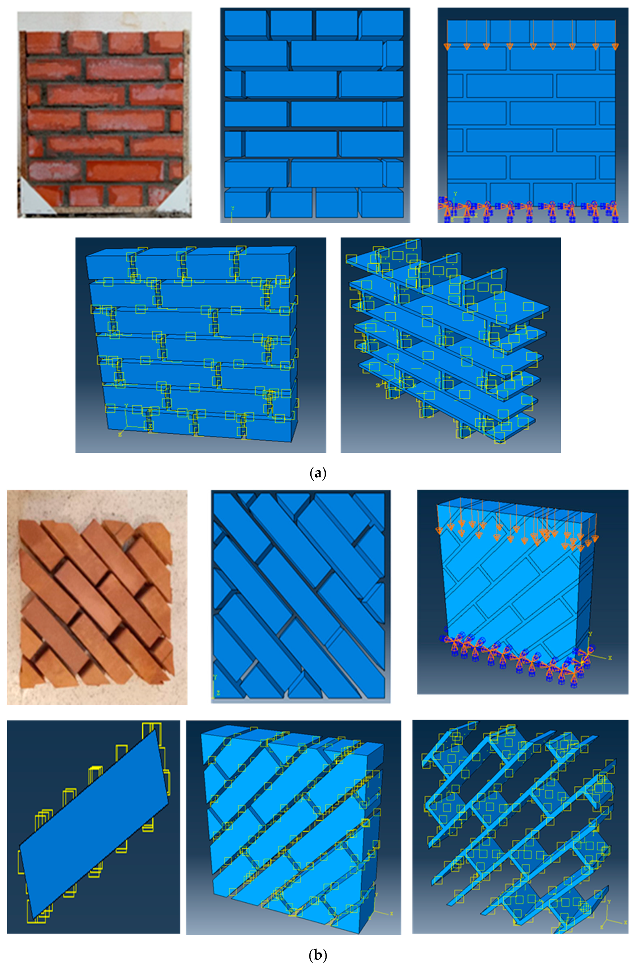
3.3. FEM Modeling for Unreinforced Masonry Wall (MTB)

3.3.1. Material Parameters

In this study, the FE software ABAQUS was used to evaluate the validity of Detailed Micro-Modeling (DMM) as a numerical model for brick masonry wall analysis. The units and mortar joints are modelled using eight-nodded 3D continuum elements with hourglass control and reduced integration (C3D8R), and the unit-mortar interface with zero thickness. The penalty friction formulation was introduced to model tangential behavior with a friction coefficient value of 0.6. The normal behavior of the interface was modeled using “hard contact”. Furthermore, the nonlinear behavior of brick and mortar was simulated by using the CDP model while the interface between unit and mortar was modeled through surface-to-surface contact. The adopted modeling strategy used in this study is illustrated in Figure 9.

3.3.2. Presentation of the Numerical Model

The numerical study will be limited to analysing the same unreinforced brick masonry wall (MCB and MTB) that was studied in the experimental part. Figure 10 shows the numerical simulation, the geometry and loading condition for the FE model that has been implemented using ABAQUS.

3.3.3. Constitutive Behavior of Units and Mortar

Concrete Damage Plasticity (CDP) Model

The CDP model provides a general capability for modeling concrete and other quasi-brittle materials, which was developed by Lubliner et al. [35], and is available in the ABAQUS [36] software library. The CDP model uses the concepts of isotropic damaged elasticity in combination with isotropic tensile and compressive plasticity [36]. This approach has been developed to predict failure modes as well as tensile fracture and the compressive crushing; it is selected in this study to simulate the nonlinear behavior of the masonry units. The level of damage is evaluated by damage parameters dc and dt. The CDP model was based on the uniaxial stress–strain relationship:
σ = ( 1 d t ) σ ¯ t + ( 1 d c ) σ ¯ c
The damaged parameter ( d c ) is calculated by Equation (6), this parameter ranging from 0 to 1:
d c = 1 σ c σ c
σ c The compressive strength of masonry
Damaged parameter ( d t ) can be calculated by Equation (7), this parameter ranging from 0 to 1.
d t = 1 σ t σ t
σ t Masonry tensile strength
The uniaxial compressive and tensile responses of concrete with respect to the concrete damage plasticity model subjected to compression and tension load were given by:
σ t = ( 1 d t ) E 0 ( ε t ε ˜ t p l )
σ c = ( 1 d c ) E 0 ( ε c ε ˜ c p l )
The effective uniaxial stress σ ¯ t and σ ¯ c were derived as follows:
σ ¯ t = σ t ( 1 d t ) E 0 ( ε t ε ˜ t p l )
σ ¯ c = σ c ( 1 d c ) E 0 ( ε c ε ˜ c p l )

Constitutive Behavior of Units-Mortar Interface

In this model, brick–mortar interface is modeled by means of Mohr–Coulomb frictional models in order to adequately reproduce the shear response of joint. Cohesion and friction angle values for Coulomb type friction model are given by the shear strength envelope for different normal stress values, which was obtained by the experimental triplet test (Figure 11). The interaction module of Abaqus/Explicit analysis was used to make the contact between units and mortar through the option surface-to surface contact. In this step, it is necessary to define two contact properties: Normal contact and tangential behavior.
Under normal behavior: The hard contact behavior normal to the surfaces is chosen. The goal is to prevent interpenetration of surfaces and to permit a separation between them once a contact has been established.
Tangential behavior: The analysis needs to take frictional forces because when the surfaces are in contact, they habitually transmit shear and normal forces athwart their interface, which resist the relative sliding of the surfaces.

3.3.4. Model Input Parameter

The input parameters used to reproduce the mechanical behavior of masonry wall using the detailed micro-modeling approach are presented. The mechanical parameters for brick and mortar employed in this analysis were obtained from tests carried out in this research (see Table 8, Table 9 and Table 10).

3.3.5. FE Modelling Results

Figure 12 shows the numerical and experimental curves of the stress–strain relationship of unreinforced walls (MCB, MTB). The numerical results show a good agreement with the experimental results concerning not only at the initial rigidity of the elastic phase but also from the non-linear phase to the post peak corresponding response. However, the values of numerical modeling are somewhat higher than that of the experimental results except the result of maximum strain for the wall sample MTB (θ = 45°). The numerical predicted deformations and peak loads for each panel compared to the average experimental results are shown in Table 11.
For the wall subjected to uniaxial compression perpendicular to bed joint (MCB), the initial cracking occurs along the vertical mortar joint as an initial response. As the vertical loads increase, more cracks occur in the vertical mortar joints of wall from top to down. After that, cracks appear and propagate in the brick units directly as a final response, which causes failure due to vertical cracking of the face shells of the masonry wall (Figure 13). The same mode of rupture was found experimentally. In MTB wall panels, cracking took place primarily through the bed and head mortar joints, and then extended diagonally. With load increasing, the wall exhibited a gradual increase in the width of the main diagonally-oriented crack, followed by sliding along the diagonal parallel to bed joints. On the other hand, many cracks appeared at the level of brick (Figure 14).
By comparing the numerically predicted damage with the observed failure pattern in the experimental test, tensile damage and thus cracking of the brick are clearly visible in the center of the wall. Otherwise, the tensile stress in the head mortar joint identified in the numerical model has not been observed by experimental test (show Figure 15). Before crushing occurred, the crack pattern appeared in the head joint (initial step), cracks through the mortar joints continued to develop vertically but with a low damage factor value. This model crack pattern was unlike those observed in the experiment test. This can be explained by the existence of micro-crack at the mortar joint but cannot be seen in the experiment test with the overall scale.
Figure 16 displays a comparison of the numerical crack pattern developed in the masonry wall MTB with that which shown by experimental tests. The damage pattern obtained by the developed numerical model is represented in term of compressive damage (DAMAGEC) and tensile damage (DAMAGET) contour plot. This comparison showed us that the crack patterns predicted in the mortar joint by the FE model and crack patterns observed during the experiment resemble each other to a good extent. A good confrontation was found not only for the crack pattern of mortar but also for the brick units. However, sometimes the position of numerical cracks at the brick differs from the experimental results, among them, crushing in the two extremities of the diagonal. This can be explained by the numerical simplification, which comprises considering that all the mortar joints have the same thickness, the same mechanical characteristics, which is not assured experimentally.

4. Conclusions

Strengthening of structures with NSM CFRP reinforcement is a technique that has attracted considerable attention as a feasible and economical method compared to externally bonded FRP reinforcement. The following conclusions were drawn from the experimental and numerical study:
  • The increase in the proportion of sand in the mortar (from 3 to 5) led to an increase in the shear strength and the ductility of the masonry panels, especially in the case of reinforcement.
  • The shear strength of unreinforced and reinforced masonry wall panel oriented by 45° was mainly related to the compressive strength of the masonry wall panel.
  • The compressive strength and shear strength of masonry panels were affected by Eunit/Emortar ratio even when this ratio was greater than one.
  • As the horizontal reinforcement restrained the opening of diagonal cracks, the sliding failures along single mortar bed joints caused by the horizontal reinforcement were prevented by the vertical reinforcement.
  • The application of CFRP strips improves and increases the ductility and the bond strength of wall masonry especially in the case of reinforcing of both sides of the panel.
  • The improvement in shear strength of strengthened wall panels with NSM CFRP strips ranged from 1.3 to 2 times (123% to 196%).
  • All reinforced wall panels showed a substantial increase in the ductility by 2.68 to 4.7 times compared with unreinforced wall panels.
  • The most significant increase in ductility was achieved by vertical NSM-FRP reinforcement in both sides of the wall panel.
  • The Finite Element model proposed in this paper shows a considerable accuracy for the prediction of maximum strength and failure mode.
  • The behavior of the masonry is strongly affected by the behavior of the interface; Coulomb friction criterion are important to simulate correctly the load transmission brick-mortar.
  • The CDP model can well reflect the damage and the non-linear behavior of brick and mortar.
  • The developed model has been proved to capture the crack patterns and the stress distribution patterns in both brick and mortar. However, the behaviour of the NSM strengthened masonry wall has not been validated since more experimental data and a particular model would be needed to substantiate this. Therefore, future work should focus on developing numerical models to analyze the wall behavior reinforced with NSM-CFRP under biaxial loading. In addition, several factors such as type of loading and the characteristics of the single component brick and mortar should be considered in future researches in order to develop a suitable and optimal design approach for strengthening of in-plane loaded masonry walls.

Author Contributions

H.H.; Conceptualization, methodology, software, validation, writing—original draft preparation. B.B.; visualization, investigation, writing—review and editing. A.K.; investigation, writing—review and editing. A.H.A.-Z.; writing—review and editing. A.G.; supervision, writing—review and editing. All authors have read and agreed to the published version of the manuscript.

Funding

This research received no external funding.

Acknowledgments

The authors thank the staff of CNERIB for their assistance to carry out this research.

Conflicts of Interest

The authors declare no conflict of interest.

References

  1. Schueremans, L. Probabilistic Evaluation of Structural Unreinforced Masonry. Ph.D. Thesis, Catholic University of Leuven, Leuven, Belgium, 2001. [Google Scholar]
  2. Van der Pluijm, R. Out-of-Plane Bending of Masonry: Behavior and Strength. Ph.D. Thesis, Eindhoven University of Technology, Eindhoven, The Netherlands, 1999. [Google Scholar]
  3. Mojsilovic, N.; Marti, P. Tests on Masonry Walls Subjected to Combined Actions; Report No. 203; Institute of Structural Engineering, ETH Zurich: Zürich, Switzerland, 1994. [Google Scholar]
  4. Hamid, A.A.A. Behaviour Characteristics of Concrete Masonry. Ph.D. Thesis, McMaster University, Hamilton, ON, Canada, 1978. [Google Scholar]
  5. Dhanasekar, M.; PAGE, A.W.; et Kleeman, P.W. The failure of brick masonry under biaxial stresses. Proc. Inst. Civ. Eng. 1985, 79, 295–313. [Google Scholar] [CrossRef]
  6. Page, A. The biaxial compressive strength of brick masonry. Proc. Inst. Civ. Eng. 1981, 71, 893–906. [Google Scholar] [CrossRef]
  7. D’Ayala, D.F.; Paganoni, S. Assessment and analysis of damage in L’Aquila historic city centre after 6 April 2009. Bull. Earthq. Eng. 2011, 9, 81–104. [Google Scholar] [CrossRef]
  8. Calderoni, B.; Cordasco, E.A.; Del Zoppo, M.; Prota, A. Damage assessment of modern masonry buildings after the L’Aquila earthquake. Bull. Earthq. Eng. 2020, 18, 2275–2301. [Google Scholar] [CrossRef]
  9. El Gawady, M.A.; Lestuzzi, P.; Badoux, M. In-plane seismic response of URM walls upgraded with FRP. J. Compos. Constr. 2005, 9, 524–535. [Google Scholar] [CrossRef]
  10. Korany, Y.; Drysdale, R. Rehabilitation of masonry walls using unobtrusive FRP techniques for enhanced out-of-plane seismic resistance. J. Compos. Constr. 2006, 10, 213–222. [Google Scholar] [CrossRef]
  11. Wylie, J.C. Experimental Testing of Unreinforced Masonry Walls Strengthened with Orthogonal Near-Surface Mounted CFRP Subjected to Out-of-Plane Loading. Master’s Thesis, North Carolina State University, Raleigh, NC, USA, 2009. [Google Scholar]
  12. Petersen, R.B.; Masia, M.J.; Seracino, R. Bond behavior of near-surface mounted FRP strips bonded to modern clay brick masonry prisms: Influence of strip orientation and compression perpendicular to the strip. J. Compos. Constr. 2009, 13, 169–178. [Google Scholar] [CrossRef]
  13. Valluzzi, M.R.; Tinazzi, D.; Modena, C. Shear behavior of masonry panels strengthened by FRP laminates. Constr. Build. Mater. 2002, 16, 409–416. [Google Scholar] [CrossRef]
  14. Petersen, R.B.; Masia, M.J.; Seracino, R. In-plane shear behavior of masonry panels strengthened with NSM CFRP strips. I: Experimental investigation. J. Compos. Constr. 2010, 14, 754–763. [Google Scholar] [CrossRef]
  15. Dizhur, D.; Griffith, M.; Ingham, J. In-plane shear improvement of unreinforced masonry wall panels using NSM CFRP Strips. J. Compos. Constr. 2013, 17, 04013010-12. [Google Scholar] [CrossRef]
  16. Maljaee, H.; Ghiassi, B.; Lourenco, P.B. Bond behavior in NSM-strengthened masonry. Eng. Struct. 2018, 166, 302–313. [Google Scholar] [CrossRef] [Green Version]
  17. Lourenço, P.B. Computational Strategies for Masonry Structures. Ph.D. Thesis, Delft University of Technology, Delft, The Netherlands, 1996. [Google Scholar]
  18. Lourenço, P.B. Structural masonry analysis: Recent developments and prospects. In Proceedings of the 14th International Brick and Block Masonry Conference, Sydney, Australia, 17–20 February 2008. [Google Scholar]
  19. Lourenço, P.B. Computations on historic masonry structures. Progr. Struct. Eng. and Mater. 2002, 3, 301–319. [Google Scholar] [CrossRef]
  20. D’Altri, A.M.; Mirandaa, S.; Castellazzia, G.; Sarhosis, V. A 3D detailed micro-model for the in-plane and out-of-plane numerical analysis of masonry panels. Comput. Struct. 2018, 206, 18–30. [Google Scholar] [CrossRef] [Green Version]
  21. Sandoval, C.; Arnau, O. Experimental characterization and detailed micro-modeling of multiperforated clay brick masonry structural response. Mater. Struct. 2017, 50, 1–17. [Google Scholar] [CrossRef]
  22. EN 771-1. Specification for Masonry Units–Part 1: Clay Masonry Units; British Standards Institute: London, UK, 2003. [Google Scholar]
  23. EN 1015-11. 1015-11. Methods of Test for Masonry. Part 1: Determination of Compressive Strength; European Standards: Brussels, Belgium, 1998. [Google Scholar]
  24. RILEM. Technical Recommendations for the Testing and Use of Constructions Materials, LUMB1-Compressive Strength of Small Walls and Prisms; Technical Report; RILEM Publications, Chapman & Hall: London, UK, 1994. [Google Scholar]
  25. Hamid, A.A.; El-Dakhakhni, W.W.; Hakam, Z.H.R.; Elgaaly, M. Behavior of composite unreinforced masonry–FRP wall assemblages under in plane loading. J. Compos. Constr. 2005, 9, 73–83. [Google Scholar] [CrossRef]
  26. Kaushik, H.B.; Rai, D.C.; Jain, S.K. Stress-strain characteristics of clay brick masonry under uniaxial compression. J. Mater. Civil Eng. 2007, 19, 728–739. [Google Scholar] [CrossRef]
  27. CSA S304. 1-04. Design of Masonry Structures; CSA: Mississauga, ON, Canada, 2004; ISBN 1-55397-402-6.H.B. [Google Scholar]
  28. BS EN, 1052-1. Methods of Test for Masonry–Part 1: Determination of of Compressive Strength; European Committee for Standardization: Bruxelles, Belgium, 1998. [Google Scholar]
  29. Augenti, N.; Parisi, F. Constitutive modelling of tuff masonry in direct shear. Constr. Build. Mater. 2011, 25, 1612–1620. [Google Scholar] [CrossRef]
  30. FEMA 306. The Applied Technology Council. Evaluation of Earthquake Damaged Concrete and Masonry Wall Buildings-Basic Procedures; Technical Report; Federal Emergency Management Agency: Applied Technology Council, CA, USA, 1999.
  31. Reddy, B.V. and C.V.U. Vyas, Influence of shear bond strength on compressive strength and stress–strain characteristics of masonry. Mater. Struct. 2008, 41, 1697–1712. [Google Scholar] [CrossRef]
  32. Park, R. Evaluation of ductility of structures and structural assemblages from laboratory testing. Bull. N. Z. Nat. Soc. Earthq. Eng. 1989, 22, 155–166. [Google Scholar] [CrossRef]
  33. Pavan, G.; Nanjunda Rao, K. Behavior of Brick–Mortar Interfaces in FRP-Strengthened Masonry Assemblages under Normal Loading and Shear Loading. J. Mater. Civil. Eng. 2016, 28, 04015120. [Google Scholar] [CrossRef]
  34. Seracino, R.; Wylie, J.C. FRP Strengthening and Repair of Unreinforced Brick Masonry Walls. 2018. Available online: https://www.reiengineers.com/wp-content/uploads/2020/02/FRPStrengtheningandRepairofUnreinforcedBrickMasonryWalls.pdf (accessed on 30 May 2020).
  35. Lubliner, J.; Oliver, J.; Oller, S.; Onate, E. A plastic-damage model for concrete. Int. J. Solids Struct. 1989, 25, 299–326. [Google Scholar] [CrossRef]
  36. Systemes, D. Abaqus/CAE User’s Guide; Dassault Systemes Simulia Corp: Providence, RI, USA, 2014. [Google Scholar]
Figure 1. (a) Brick units; (b) compression test; (c) bending test on the brick.
Buildings 10 00103 g001
Figure 2. (a) Test setup; (b) configuration of unreinforced masonry walls (θ = 90°, θ = 45°); (c) configuration of reinforced masonry walls (θ = 45°).
Buildings 10 00103 g002
Figure 3. Specimens’ preparation and NSM-CFRP strips installation.
Buildings 10 00103 g003
Figure 4. (a) Failure modes; (b) stress-strain responses of masonry panels (MCA, MCB).
Buildings 10 00103 g004
Figure 5. Masonry assemblage under combined shear and compression.
Buildings 10 00103 g005
Figure 6. (a) Failure mode of unreinforced masonry walls 45° (MTA); (b) failure mode of unreinforced masonry walls 45° (MTB); (c) parallel and shear stress–strain relationships for masonry walls.
Buildings 10 00103 g006
Figure 7. Failure modes of all reinforced masonry walls.
Buildings 10 00103 g007aBuildings 10 00103 g007b
Figure 8. Shear stress–strain relationship for MRA and MRB reinforced masonry walls.
Buildings 10 00103 g008
Figure 9. Adopted detailed micro-modeling (DMM) approach.
Buildings 10 00103 g009
Figure 10. Numerical model (DMM), boundary conditions and interface contact of unreinforced brick masonry walls: (a) wall MCB (θ = 90°); (b) wall MTB (θ = 45°).
Buildings 10 00103 g010
Figure 11. (a) Relationship between maximum shear stress and normal stress of shear triplet test; (b) stress–strain curves for various pre-compression of walls.
Buildings 10 00103 g011
Figure 12. Experimental and numerical curves of stress–strain relationship of unreinforced walls.
Buildings 10 00103 g012
Figure 13. (a) Principal stress; (b) normal stress in the direction y (S22); (c) evolution of damage in unreinforced wall MCB (θ = 90°).
Buildings 10 00103 g013
Figure 14. (a) Von Mises stress; (b) normal stress in the direction y (S22); (c) evolution of damage in unreinforced wall MTB (θ = 45°).
Buildings 10 00103 g014
Figure 15. (a) Experimental crack pattern; (b) numerical crack pattern of unreinforced wall (MCB).
Buildings 10 00103 g015
Figure 16. (a) Experimental crack pattern; (b) numerical crack pattern of unreinforced wall (MTB).
Buildings 10 00103 g016
Table 1. Compressive strength (fc) and Young’s modulus (E) of mortars and bricks.
Materialfc (MPa)Young’s Modulus E (MPa)
Brick14.59839
Mortar A (1:1:3)7.23639
Mortar B (1:1:5)3.61822
Table 2. Mechanical properties of the CFRP reinforcing system.
PropertyValue
CFRP width15 mm
Thickness2.5 mm
Young’s modulus (E CFRP)165,000 MPa
Tensile strength (Ft CFRP)3100 MPa
Rupture strain1.7 %
Table 3. Walls dimensions and CFRP retrofit details.
StageWalls CodeWalls DetailsOrientation (θ)Mortar TypeDimensions Walls (mm)Joint Thickness (mm)Retrofit Details
1MCA MCBControl panels90°A400 × 400 × 10510Without
B
2MTA MTBControl panels45°A400 × 400 × 10510without
B
3MHAReinforced panels45°A400 × 400 × 10510Two horizontals strips on one side
MVATwo verticals strips on one side
MR2ATwo verticals strips on one side and two horizontals strips on the other side
4MHBReinforced panels45°B400 × 400 × 10510Two horizontals strips on one side
MVBTwo vertical strips on one side
MR2BTwo vertical strips on one side and two horizontals strips on the other side
Table 4. Comparison of experimental results Young’s modulus (E) with analytical predictions.
Calculation Formula of Emac (MPa)Calculated Values Emac (MPa)Experimental Values Emac (MPa)
Mortar Type AMortar Type BMortar Type AMortar Type B
E,mac ≈ 1000σc, mac [27]222621641082.071391.25
E,mac ≈ 850σc, mac ≤ 20,000 [28]18391892.1
E,mac ≈ 550σc, mac [29,30]1245.21224.3
Table 5. Mechanical properties of masonry panels.
θ°Wall PanelsEunit/Emortar = β
β = 2.7 (Mortar Type A)
Eunit/Emortar = β
β = 5.403 (Mortar Type B)
Shear Strength (MPa)Compressive Strength (MPa)Young’s Modulus (MPa)Shear Strength (MPa)Compressive Strength (MPa)Young’s Modulus (MPa)
90°MC-----2.161082.07-----2.231391.26
45°MT0.821.65300.081.082.17324.60
MRH1.012.00100.941.543.09138.96
MRV1.082.16117.21.613.23165.94
MR21.533.05156.722.124.23458.31
Eunit: Young’s modulus of bricks. Emortar: Young’s modulus of mortars.
Table 6. Comparison of uniaxial compressive stress of unreinforced and strengthened masonry panels.
Bed Joint OrientationType of MortarWall PanelsFmax (kN)σ1 (MPa)Age Increase (%)σn (MPa)σp (MPa)τnp (MPa)
θ = 90°Type AMCA97.72.12----2.16------0
Type BMCB100.52.23-----2.23------0
θ = 45°Type AMTA Panel control69.21.65-----0.820.820.82
MRHA Single side85.12.001231.011.011.01
MRVA Single side90.02.161311.081.081.08
MR2A both sides179.03.051851.521.521.52
Type BMTB Panel control91.02.17----1.081.081.08
MRHB Single side129.703.091421.541.541.54
MRVB Single side135.503.231491.611.611.61
MR2B both sides180.104.231962.122.122.12
Fmax: ultimate load; 1: Average uniaxial compressive strength; n: Stress normal to bed joint; p: Stress parallel to bed joint; np: Shear stresses on bed joint; Age increase (%): the ratio of Fmax of reinforced panel to the control panel.
Table 7. Comparison of the displacement ductility factor of all tested masonry panels.
Wall PanelsYoung’s Modulus E (MPa)Shear Modulus G (MPa)γeγuμμuo (%)
MCA1082.07483.130.0140.0151.06-----
MTA300.08125.030.0090.0051.12-----
MRHA100.9442.100.0050.023.83342
MRVA117.2049.010.0060.0233.85343
MR2A156.7265.340.0050.0194.38391
MCB1391.26570.180.0110.0131.09------
MTB324.60137.250.0080.0061.21------
MRHB138.9657.900.0060.0172.68222
MRVB165.9469.130.0060.0274.60384
MR2B458.3176.980.0050.0244.70392
uo): ratio of ductility of reinforced wall panels when compared to the corresponding control wall panel.
Table 8. Mechanical properties of masonry unit and mortar.
Elasticity ParametersBrickMortar
density γ (kg/m3)2.2 × 1031.8 × 103
Young’s modulus, E (MPa)10,0001880
Poisson ratio ν0.20.18
Table 9. Concrete damage plasticity of masonry brick and mortar.
Plasticity Parameters
Dilation angle (Ψ)20
Eccentricity parameter (e)0.1
Biaxial and unidirectional initial compressive strength ratio (fb0/fc0)1.16
Stress ratio in tensile meridian (K)0.67
Viscosity Parameter ( υ ) 0.0001
Table 10. Compressive and tensile Behavior of brick and mortar.
MaterialCompressive BehaviorTensile Behavior
Stress (MPa)Inelastic Strain (×10−4)Stress (MPa)Cracking Strain (×10−4)
Bricks12.102.50
13.21.42.21.4
14.198.31.64.2
12.6517.71.17.0
11.7721.90.611.2
1126.90.121.0
Mortars5.9801.630
6.0510.751.535.91
6.1011.501.446.95
6.2118.001.2613.20
6.2820.251.1422.93
6.3627.751.1331.50
Table 11. Comparison of numerical result with experimental data.
ParameterWall Panels
θ = 90° (MCB)θ = 45° (MTB)
ExperimentalNumericalC.O.V (%)ExperimentalNumericalC.O.V (%)
Fmax (kN)100.1188.608.6280.7667.2012.9
σmax (MPa)2.231.978.751.921.6012.8
ε max0.0160.01600.0140.02231.4
C.O.V: Coefficient of variation.

