Floor Slabs Made from Topologically Interlocking Prefabs of Small Size


Department of Architectural Design and Engineering Graphics, Faculty of Civil and Environmental Engineering and Architecture, Rzeszow University of Technology, 35-959 Rzeszow, Poland
Buildings 2020, 10(4), 76; https://doi.org/10.3390/buildings10040076
Submission received: 22 February 2020
/
Revised: 7 April 2020
/
Accepted: 12 April 2020
/
Published: 15 April 2020
(This article belongs to the Section Building Structures)
Abstract
:In this article, the issue of constructing slabs from unified small elements, which are connected together into a stable structure by topological interlocking, is considered. The state-of-the-art methods in this topic are presented, as well as the results of the author’s original research. The author has expanded the well-known concept of shaping square slabs from square prefabs by the aggregation of triangular and hexagonal slabs from prefabs in the shape of equilateral triangles, regular hexagons, and rhombuses. Each of the slabs can be modelled with upper and bottom surfaces, either both relief, both smooth, or one relief and the other smooth. The slabs can be modelled in different ways, and each one results in intriguing floor and ceiling patterns. All of the slabs can co-operate with grillages made of steel beams, which can be constructed before filling with the prefabricated slab, which is a novel idea. Reversing the assembly order, as compared to that used in the literature, is made possible thanks to division of these elements into parts, to form a keystone which is inserted into the slab as a final step.

1. Introduction
The research problem presented in this paper concerns an issue specified in the scientific literature as flat vault technology or topological interlocking. In particular, it considers the construction of flat slabs from cut stones which are significantly smaller in size than the slab, without the use of mortar or any other sticky substance. Slabs constructed in this way remain stable, due to the fact that properly shaped components support each other. Statically, it behaves as a typical slab supported at its perimeter, which is an advantage as the values of its bending moments are smaller than those in slabs which are only supported in one direction. On the other hand, the slab is a vault, which results in the presence of thrust forces (as in every vault). As the vault is flat in this case, the thrust works in a horizontal plane, which it causes problems in balance around the circumference of the slab. This is a major drawback of such structures.
2. State-of-the-Art
2.1. Historical Heritage
The issue of constructing flat vaults from elements shaped in such a way that they establish a self-supporting structure due to topological interlocking has been the subject of theoretical considerations and attempts of practical implementations undertaken for several centuries. The first designs were based on the idea of a structural stone arch, the transfer of which to a flat structure resulted in a variety of shapes of individual elements, according to the position of the element in the structure. A stone vault of this type, dated from 1559–1584, has been preserved in the Eskurial monastery in Spain [1]. The 280 mm thick structure was realized above a square room with dimensions of 8 × 8 m. As the manufacture of non-uniform elements with precision while ensuring a tight fit is difficult, researchers’ efforts have been redirected to finding a solution which allows the construction of a flat vault out of identical elements.
The first concepts of flat vaults built from unified small elements were presented in 1699 by Abeille and Truchet [2] and then in 1737 by Frezier [3]. The elements were arranged such that each element supported two other elements and was supported by another two elements. This idea was based on the concept of floor structures made of reciprocal timber beams, which has been known since the 17th century and popularized by Wallis (as Serlio’s floors), immediately before the announcement of the mentioned inventions [4]. The differences between the concepts of Abeille, Truchet, and Frezier are manifested in the shapes of the blocks used. Abeille started from a vault characterized by the fact that one of its surfaces is smooth, while the other is relief (Figure 1a). Truchet designed a vault with both smooth surfaces, obtained as a result of the use of blocks with curvilinear edges and non-flat faces (Figure 1b). Frezier found two different straight-edged block shapes, the use of which resulted also in the construction of vaults with two smooth surfaces (Figure 1c,d).
Two structures using this idea, both from the second half of the nineteenth century, have been preserved in Spain: the first one is in the cathedral of Lugo [5] and the second one is in the Casa Mina de Limpia, near Madrid [6]. Both vaults are small; for example, the internal dimensions of the latter one are 310 × 380 cm, and a thickness of 22.5 cm. The side length of the square that forms the basis of a single block is 36 cm, which means that the vault was made of 99 blocks arranged in 9 rows containing 11 blocks each [7]. The size of the vault is limited by the problem of balancing the thrust, which becomes larger for greater-sized vaults.
2.2. Contemporary Research
At present, increased interest in this issue can be observed in the fields of architecture and material engineering. The first paper which undertook the subject of shaping material structures from interlocked tetrahedron-shaped elements was published in 2001 [8]. Dyskin et al. first introduced the term topologically interlocking to describe the specific spatial properties of such a material [9]. A limited number of theoretical papers dedicated to shaping flat slabs which are applicable in architecture have been written in recent years [10,11], as well as on the experimental research carried out in this area [12,13].
An important problem is the tendency of elements to move in horizontal directions, caused by the action of the thrust force. A popular method proposed in the literature to counteract such displacements is the use of a perimeter frame made of steel beams. Laboratory tests of slabs made of concrete blocks surrounded by a frame of steel sections were carried out in France by Sakarovitsch and Fleury. Sakarovitsch tested square slabs with side lengths from 2.4 to 3 m, assembled from 36, 64 or 81 identical blocks [12] and Fleury-slabs with side dimensions 1.25 and 2.5 m, composed of 49 blocks [13]. Both in theoretical considerations and experiments on models made at a natural [12,13] or reduced scale [11], it has been assumed that the frame must be assembled after arranging all the elements of the vault; or, at least, that the last element of the frame cannot be mounted until then. Despite of presence of the peripheral frame, the dimensions of a vault cannot be large, due to the occurrence of excessive deflections.
The visual attractiveness of the Abeille and related vaults, as well as the ease of prefabrication resulting from the uniformity of components, have provided inspiration in the search for the possibility of shaping forms other than flat ones. Fallacara noted that every flat vault pattern can be used to build a curved vault by transposition onto a cylindrical surface [14]. He materialized his observation in several prototypical structures which had been not intended to achieve utility goals but, instead, aspired to be called works of art. The most spectacular arch vaults are the entrance portal to the Cities of Stone pavilion at the International Architectural Exhibition in Venice in 2006 and the Truchet bridge, built as a part of the summer school of the University of San Pablo in Madrid in 2007. The realization of both structures became possible thanks to the use of CAD-CAM technology [15]. Further studies into the shaping of spatial structures from Abeille blocks, both conducted by Fallacara et al., as well as other researchers, has led to the development of methods to model structures with double curvature, especially spherical structures [16]. More advanced achievements in the field of shaping spherical structures using the Abeille system have been presented by Brocato and Mondardini [17,18]. They comprehensively solved the geometric problems, as well as they performed complex static analysis using Final Elements Method (FEM). They solved the problems of geometric shaping, as well as they performed static analysis using FEM, which included on whole family of numerical models differed by geometric parameters. Although the investigation did not include at all research on physical models, the FEM analysis is nowadays commonly used also in relation to masonry structures of existing buildings [19].
3. Geometrical Shaping of Slabs
3.1. Bases of the Method of Shaping Prefabs
The procedure of shaping the components useful for the aggregation of flat vaults has been outlined, in general, by Irina Miodragovic Vella and Tony Kotnik [20], as well as by Michael Weizmann et al. [11]. It is based on the initial establishment of a grid of polygons contained in the plane σi, followed by insertion the planes αij perpendicular to the plane σi, through the sides of these polygons αij, and then rotation of the planes αij by the same angles ϕ. For a grid composed of squares (Figure 2a), the rotations of the planes α4j passing through the opposite sides of the square take place in the positive direction for one pair of these sides and in the negative direction for the other pair (Figure 2b). After the addition of two planes β1 and β2 parallel to the plane σi, located on both sides of it and at equal distance from it, the section of space surrounded by the planes α4j, β1, and β2 determines the geometrical model of the vault component (Figure 2c). A vault consisting of components formed according to this principle is characterized by concavities analogous to those in the Abeille vault, but arranged on both slab surfaces. The advantage of such an arrangement is a lower dead load of the vault; while the concavity is not a disadvantage, due to the necessity of covering them by the layers constituting a functional floor.
The method described above allows one to shape the components of the flat vault on the basis of any polygon. Considering brevity and utility, only polygons that can be used for the creation of a repetitive element useful in various vaults will be considered; so, in addition to squares, regular hexagons and equilateral triangles are considered. For a hexagon, the rotations of the planes α6j through its sides (Figure 3a) are: for planes with odd values of the index j, the rotations are by the angle ϕ in the positive direction; for planes α6j with even indices, the rotations are in the negative direction (Figure 3b). The geometric model of the hexagonal component is cut out of the space by the planes α6j and the planes β1 and β2, located analogously as for the square component (Figure 3c).
The aggregation of structures only from triangular elements is not possible. The use of triangular components in flat vaults can be considered, provided that they co-create these vaults together with components characterized by a larger number of sides and that they occupy only such a position where two of the three side faces are supported by other components and at most one of the three side faces of these components serve as a support for another component. Geometric models of triangular components are obtained in such a way that two of the three planes α3j (Figure 4a) are rotated from the initial position by a positive angle and the remaining third plane is rotated by a negative angle, or vice versa (Figure 4b).
As the volume of a triangular element, shaped in the same manner as square and hexagonal elements (Figure 4c), is larger than the volume of the spatial cell bounded by the planes β1, β2, and α3j at their initial positions, this may prevent the component from fitting with adjacent ones. Therefore, the final shape of the triangular component is determined by means of an additional plane β3 passing through the vertex C, parallel to the line AB and rotated from a position perpendicular to the plane σ3 in a direction contrary to the rotation of the plane α31 (Figure 4d). The function of the plane β3 is to cut off the excess volume of the component, in order to facilitate the use of it in the construction of slabs.
The last polygon which is examined is a rhombus. The modeling procedure for a rhombic component is fully analogous to the procedure explained for square components; that is, the planes passing through one of the pairs of the opposing rhombic sides (Figure 5a) should be rotated by the angle ϕ in the positive direction and those passing through the sides of the second pair in the negative direction (Figure 5b). The geometrical model of a rhombic component is cut out of space with the planes α4j and with planes β1,2 parallel to the base plane σ4 (Figure 5c).
3.2. Composing Square, Triangular and Hexagonal Slabs
Components based on regular hexagons, equilateral triangles, and rhombuses are provided to construct slabs based on a regular hexagon and an equilateral triangle. The use of hexagonal components is possible for both hexagonal and triangular fields, but is it not possible to fill the entire field with these components—it is necessary to make auxiliary use of components based on equilateral triangles. The stability of an assembly composed of hexagonal and triangular elements will be maintained if, in the whole assembly, the number of edges supported exceeds the number of edges forming supports. The number of supported edges should include the edges contained in the sides of the slab, assuming that it will be supported along the circumference.
The above reasoning allows us to check whether an assembly of triangular and hexagonal slabs from components based on equilateral triangles and regular hexagons is possible, as well as the maximum number of triangular components that can be used to ensure the stability of the vault. It is assumed that n is the length of the polygon’s side, expressed as a multiple of the number of components: xi is the number of triangular components in the i-angle plate and yi is the number of hexagonal components in the i-angle plate. The total number of components in a triangular field is determined by Equation (1) and in a hexagonal field by Equation (2). Assuming that each triangular component must be supported at two edges and that a hexagonal component must be supported at three edges in order to maintain stability, Equation (3) determines the relationship for a triangular field and Equation (4), similarly, for a hexagonal field. Equation (3) allows calculation of the maximum number of triangular components in a triangular field (Equation (5)) and, in combination with Equation (1), the minimum number of hexagonal components for such a field (Equation (6)). By analogy, on the basis of Equations (2) and (4), it is possible to calculate the maximum number of triangular components (7) and the minimum number of hexagonal components (Equation (8)) for a hexagonal field. Conditions (Equation (6) and (8)) are in the form of inequalities (and not equations) due to the fact that the number of components must be a natural number.
Each of the components described in Section 3.1 can be considered to be in the position shown in the figures, or “upside down” (after inverting). The reversal of hexagonal and rhombus components does not change the number of supported and supporting edges. After reversing a triangular component, instead of two faces with a slope matched towards the possibility of resting on other components (Figure 6a), only one face assumes such a slope (Figure 6b). For this reason, a triangular component cannot be used in an inverted position. Exceptionally, it can be used in this position in the peripheral zone of the slab, in such a way that the support of the slab along the edge assumes the role of an additional support for this triangular component (Figure 6c). With reference to the situation described above, the conditions expressed by Equation (6) and (8) should be treated as necessary but not sufficient conditions. This means that not every configuration of components shaped according to the principles shown in Figure 2, Figure 3, Figure 4 and Figure 5, which fulfil the conditions (Equation (6) or (8)), forms a self-supporting structure. Therefore, a detailed analysis of all fragments is essential. Figure 7a shows triangular self-supporting structures. This universal principle allows us to compose hexagonal elements and triangular structures with any value of the parameter n. The use of these elements to compose hexagonal structures is possible only when the value of parameter n equal to 2 or 3 (Figure 7b).
The alternative way of constructing hexagonal slabs consists in setting them together using components based on considering a rhombus as the sum of two equilateral triangles. Rhombic components can be combined into hexagonal assemblies—three pieces each [5]—from which larger structures can be created, or can be linked together similarly to square components. The first method is effective for hexagonal structures characterized by values of parameter n equal to 2 or 3 (Figure 8a); however, structures of any size can be created by use of the second method (Figure 8b). The assembly of structures from rhombic components requires the use of two types of such components, one according to Figure 5c and its symmetric mirror image. Mirror components are shown, in Figure 8, in a lighter color.
Rhombic components can also be used in conjunction with triangular components. In such a way, both triangular and hexagonal structures can be aggregated. Each of the structures shown in Figure 6 can be replaced by a structure in which, instead of any hexagonal component, three rhombic components are used (Figure 9a,b). All the rhombic components forming a three-element system are identical. However, individual systems can be made of components compliant with that of Figure 5c, or of those formed by their mirror images. Another option is to construct structures by assembling them only from hexagonal- and rhombic-shaped components. This method is effective only for hexagonal structures characterized by values of the parameter n equal to 2 or 3 (Figure 10). The logical consequence is the possibility to use three types of components (i.e., hexagonal, triangular, and rhombic) into a single structure. This significant freedom in the selection of the configuration of the structure allows for differentiation of ornamentation on the surfaces of slabs of the same dimensions. The presentation of a wide range of structures differing in the configuration of elements is made below, with intention to compare the visual attractiveness of the ornaments on the upper and lower surfaces of the vault.
3.3. Double-Sided Rough, Smooth-Rough, and Double-Sided Smooth Slabs
Slabs made of prefabs, the shapes of which were discussed in Section 3.1, are characterized by the roughness of both surfaces; that is, the top and bottom surfaces. Their use in the role of floor slabs can be taken into account, provided that at least the upper surface will be covered with a floor layer levelling the cavities. Roughness on the bottom surface of the slab can function as a decorative ceiling motif. However, shapes of prefabricated elements which will ensure the smoothness of at least one of the slab surfaces may be found. For a square mesh, Abeille block prefabs ensure the smoothness of one of these surfaces, and smoothness of both limiting surfaces is ensured by Truchet and Frezier blocks. Blocks inspired by Abeille can also be modeled on the other considered polygons (i.e., regular hexagons, equilateral triangles, and rhombuses), based on a procedure similar to that described in Section 3.1. The role of one of the planes defined earlier as β1 and β2 is played by the plane σi, and the second one—the plane β4—is shifted in relation to the plane σij by the distance equal to the expected thickness of the slab (Figure 11).
The rotations of the planes αιj in directions opposite to those indicated in Figure 2, Figure 3, Figure 4 and Figure 5 were not taken into consideration in Section 3.1, as such an action results in forming prefabs whose orientation in space is reversed, but are exactly the same shape. Prefabs modeled analogously to Abeille blocks cannot be embedded into the structure in an inverted position, as the edges contained in the plane β4 determine a grid different from the mesh contained in the plane σi. Taking alternative actions on the planes αij leads to the formation of identical hexagonal prefabs, but the triangular prefabs obtained in such a way are the mirror images of their prototypes (Figure 11a). These mirror copies (Figure 11b) do not require shape correction using the β3 plane (Figure 11c). In the case of rhombic prefabs, inversion of the rotation direction of the planes α4j result also in the creation of mirror image variants (Figure 11d,e).
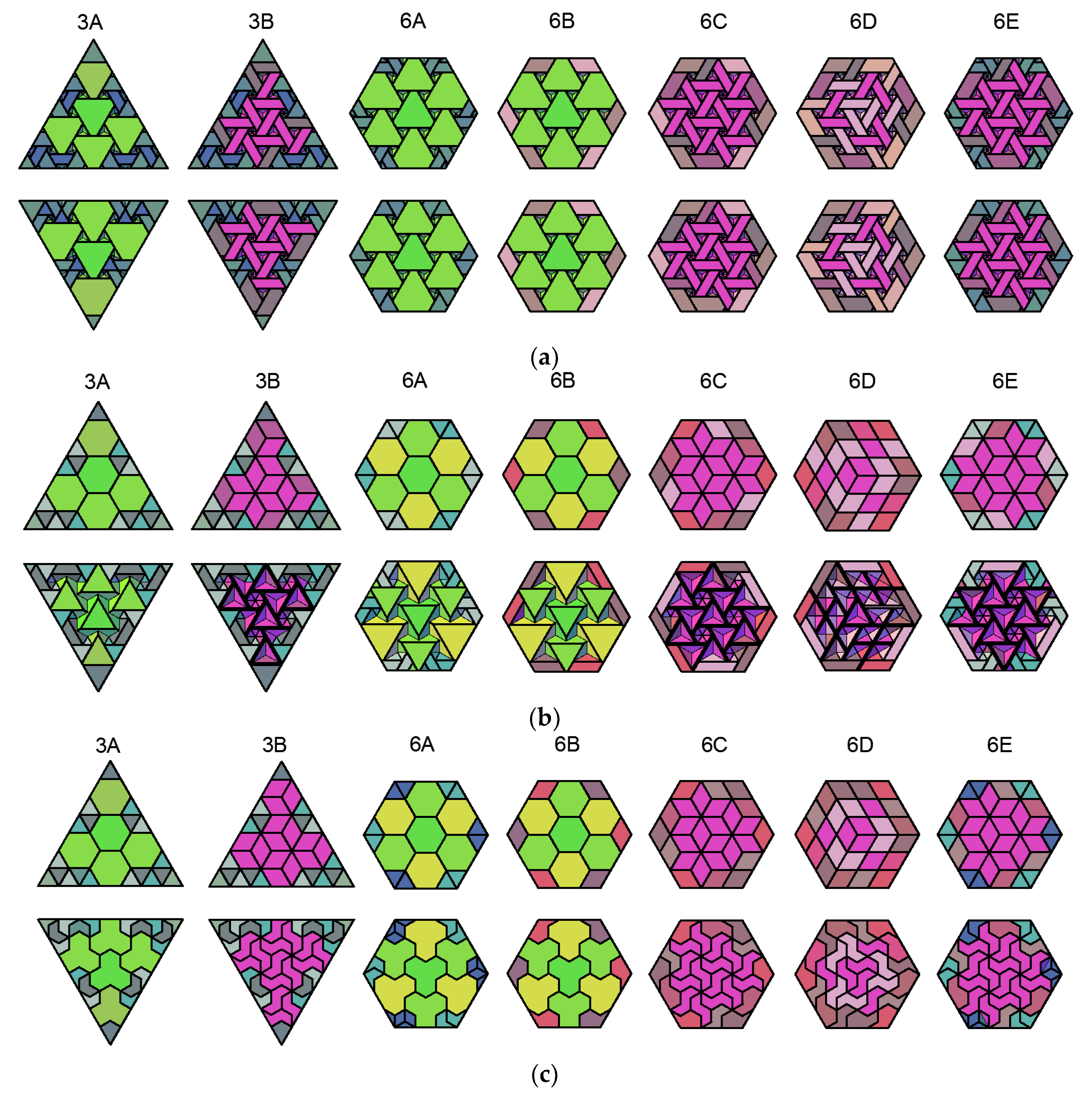
Examples of structures comprised of prefabs inspired by Abeille blocks based on regular hexagons, equilateral triangles, and rhombuses are shown in Figure 12. The smooth surfaces of the prefabricated slabs are shown in the upper line, while the rough ones are shown in the bottom line. The criterion for selecting the slabs compared in Figure 12 is that the configuration must be complex enough to include all the fragments typical of more complex structures, as well as so simple that each of the fragments occurs in the compared slabs only once. With regard to hexagonal structures, the variety of forms is important, which is available for parameter n no higher than 3. Two triangular structures, shaped alternatively according to both rules defined in Figure 7a and Figure 9a, for which the value of the parameter n is 7, as well as five hexagonal structures shaped according to the rules defined in Figure 7b, Figure 8a,b, Figure 9b, and Figure 10, for which the value of the parameter n is 3, are compared.
Modeling prefabs, based on a regular hexagon, an equilateral triangle, or a rhombus, inspired by the Truchet and Frezier blocks (and, so, enabling construction of slabs which are smooth on both sides) is also possible. More chances for practical application are possible using Frezier modeling, due to the flatness of the component side walls. Triangular, hexagonal, and rhombic components can be shaped analogously to each of the two blocks presented by Frezier.
The dimensions of the components are subject to restrictions connected with the scant volume of the triangular prefabricate, in which there must be enough space to contain the convex parts of the two neighboring components. The solution of this problem for prefabs of the first type is shown in Figure 13a, and for prefabs of the second type in Figure 13b. The parts referred to above may come into contact with each other at most along the edges indicated in Figure 13a,b in red, but may not enter into one another. The angles marked on the horizontal views of prefabs in red must be equal to and must not exceed 30°. The extreme values of parameters subject to limitation—atmax (Figure 13a) and θtmin (Figure 13b)—are defined by Equation (9) and (10). Due to the contact of components based on different polygons, the conditions for the triangular prefabs must be reflected in the shapes of prefabs based on regular hexagons and rhombuses as well (Figure 14a,b).
Vaults inspired by Frezier blocks are presented in Figure 15, in an example of structures from components modeled on blocks of the second type. A convention identical to that in Figure 12 has been adopted (i.e., particular surfaces limiting the slab), which is shown in the different rows of the figure.
4. Co-Operation of Slabs with Structural Grillages
4.1. Assumptions
The thrust acting in the vault plane, the value of which is comparable to the value of the applied vertical load, is one of the factors limiting the utility of flat vaults. The authors of experiments and theoretical studies [11,12,13] have turned to the use of a frame made of steel profiles surrounding the vault, in order to eliminate the horizontal displacement of prefabricates caused by the action of the thrust force (Figure 16), which in such a case can get transferred by tensile forces in the perimeter frame. The material typically used to make vault components is concrete. The results of tests carried out on models made from concrete clearly show that the dimensions of vaults constructed in the manner discussed above cannot be significant. In addition, the existing solutions are based on the assumption that the frame is assembled around the previously arranged vault, as the shapes of the components, reflecting the principle of reciprocal co-operation, do not allow reversal of the order of assembly (i.e., arranging the vault inside an already-made frame).
To solve the problem of balancing the thrust and dimensional constraints in vaults, co-operation with structural grillages made of steel beams can be used. It would allow joining individual vaults, with dimensions such as those known from existing implementations [5,7] and tests [12,13], into larger structures. As one of the tasks facing the beams is a static response to horizontal forces, the prefabricated slab should not be located on the top surfaces of the beams, but between them. The cross-sections of beams should be arranged such that the slab can be supported on the bottom flanges, while the webs protect the prefabs against horizontal displacements. From this point of view, the use of beams with an I-profile is optimal. Grillages can also be constructed using rectangular pipes, provided that an additional metal sheet with a width greater than the width of the profile is attached to the bottom side of the profile, in order to create a support for the slab (Figure 17).
The slabs which can be aggregated from the prefabs described so far are suitable for co-operation with grillages on regular grids (i.e., orthogonal, triangular, and hexagonal) or semi-regular grids composed of equilateral triangles and regular hexagons. Using the same components to fill grillage fields of different dimensions is possible, provided that the beam configuration is developed on a modular mesh, which results in the division of fields into repetitive cells in different fields. Two solutions are possible: using the modular planes as the center planes of the beams (Figure 18a), or containing the side faces of the beams (Figure 18b). The choice of the first solution results in differentiation of the horizontal dimensions of the border and internal components; although, if the beams are made of I-sections, the difference between their dimensions is minimal. The second solution determines the same horizontal dimensions of all components, although the peripheral ones still differ from the internal components, due to the need to fit to the vertical faces of the beams. The covering of fragments of precast elements with the flanges of the I-beams is a circumstance that decreases the aesthetic value of the ceiling (or floor, in the case of a grillage-floor filled with topologically blocking prefabs). In order to eliminate this defect, the peripheral prefabricates should be larger.
The construction of a grillage from hexagonal pipes is one way which uses only typical prefabs, such as the ones described in Section 3.1, both as internal and peripheral elements. The arrangement of the pipes must be such that the modular planes pass through the edges of the pipes which are most distant from the centre plane of their cross-section. The condition for prefabs touching the walls of the hexagonal profiles is that the inclination of the side walls of prefabs must be at an angle of 60° to the horizontal plane (Figure 19). In this case, the prefabs constituting the peripheral rows find (by their upper parts) support on the pipes, while the lower parts of the prefabs do not collide spatially with the pipes. In prefabricates in the reverse position, the upper part rests on the neighbouring prefabs and the bottom part touches the bottom part of the pipe. The construction of a prefabricated floor slab with one or both smooth surfaces is not possible with the use of a grillage made of hexagonal pipes, due to the spatial conflict of the pipes and prefabs.
4.2. The Assortment of Prefabs
The co-operation of a prefabricated slab with a grillage made of I-profiles or rectangular pipes requires that the surfaces limiting the prefabs from the side adjacent to the beams are vertical, in order to ensure contact between the prefabricates and the vertical faces of beams. This means that prefabricates intended for use in the extreme rows must differ from the internal prefabs and, thus, the assortment of elements necessary to fill the whole grillage must be larger. This number depends on the type of the slab (rough or smooth) and its shape (square, hexagonal, or triangular). Slabs which are rough on both sides require the least varied assortment, as the components—which are characterized by internal symmetry—can co-create the structure of such a vault also after reversal.
Filling a quadratic field with a relief vault requires, aside from standard elements, one type of edge element and a corner element: in one variant, if the number of strips is even; or in two variants (being mutual images in mirror symmetry), if the number of strips is odd (Figure 20a). Smooth vault components are functional only in a specific spatial orientation; hence, the entire assortment always includes two types of edge components, regardless of whether the vault is one-sided (Figure 20b) or smooth on both sides (Figure 20c). Figure 20 shows the slabs in analogous convention as in Figure 12 and Figure 15. The components of one-side smooth slabs can be shaped in such a way that the slab is characterized by a non-zero thickness at each point. This modification consists of enlarging the components from the side of a smooth outer surface by a layer of constant thickness (Figure 21).
The issue of the number of prefabs necessary for the construction of triangular and hexagonal prefabricated slabs is more complex, due to the greater variety of schemes according to which the slabs can be constructed. An analysis was made on slabs analogous to those shown in the figures below. Figure 22a shows surfaces of slabs with both sides rugged; Figure 22b shows surfaces with one side smooth; and Figure 22c shows surfaces which are smooth on both sides. The components with different shapes have been highlighted with different colors.
4.3. The Stacking Order of the Precast
The assembly of the components co-creating the vault should be carried out on a temporary scaffolding, which can be dismantled only after the vault has been completely assembled and the components have been topologically blocked. The limitations the grillage beams impose on the freedom of manoeuvring prefabs has made it necessary to develop some special assembly solutions. As mentioned in Section 3.1, the shapes of topologically blocking components do not allow the assembly of the slab inside a previously made framework; the solution to this problem is the replacement of some standard components by identical shapes, but divided into parts. The role of these multi-element prefabs is similar to the role of the keystone in a stone arch (i.e., of the cut stone which, introduced last, stabilizes the position of all other ones and causes the transformation of a set of separate elements into a uniform structure).
The division of the keystone-like components into parts should ensure that the first part can be inserted into the hole which remains after laying the typical prefabs, is able to rest on them, and provides support for the next part, whose shape should allow insertion into the hole which remains after its insertion. The number of these specific components and the number and shapes of the parts to be divided depend on the shape of the vault and its type (i.e., the types of top and bottom surfaces). Installation of the slab should be made from the perimeter towards the centre. Corner components should be arranged first, as the freedom to manoeuvre them is relatively the smallest. Subsequently, edge components should be laid, starting from those whose bottom bases (measured along adjacent beams) are larger than the upper bases. Next, internal components should be laid until the insertion of one more component becomes impossible.
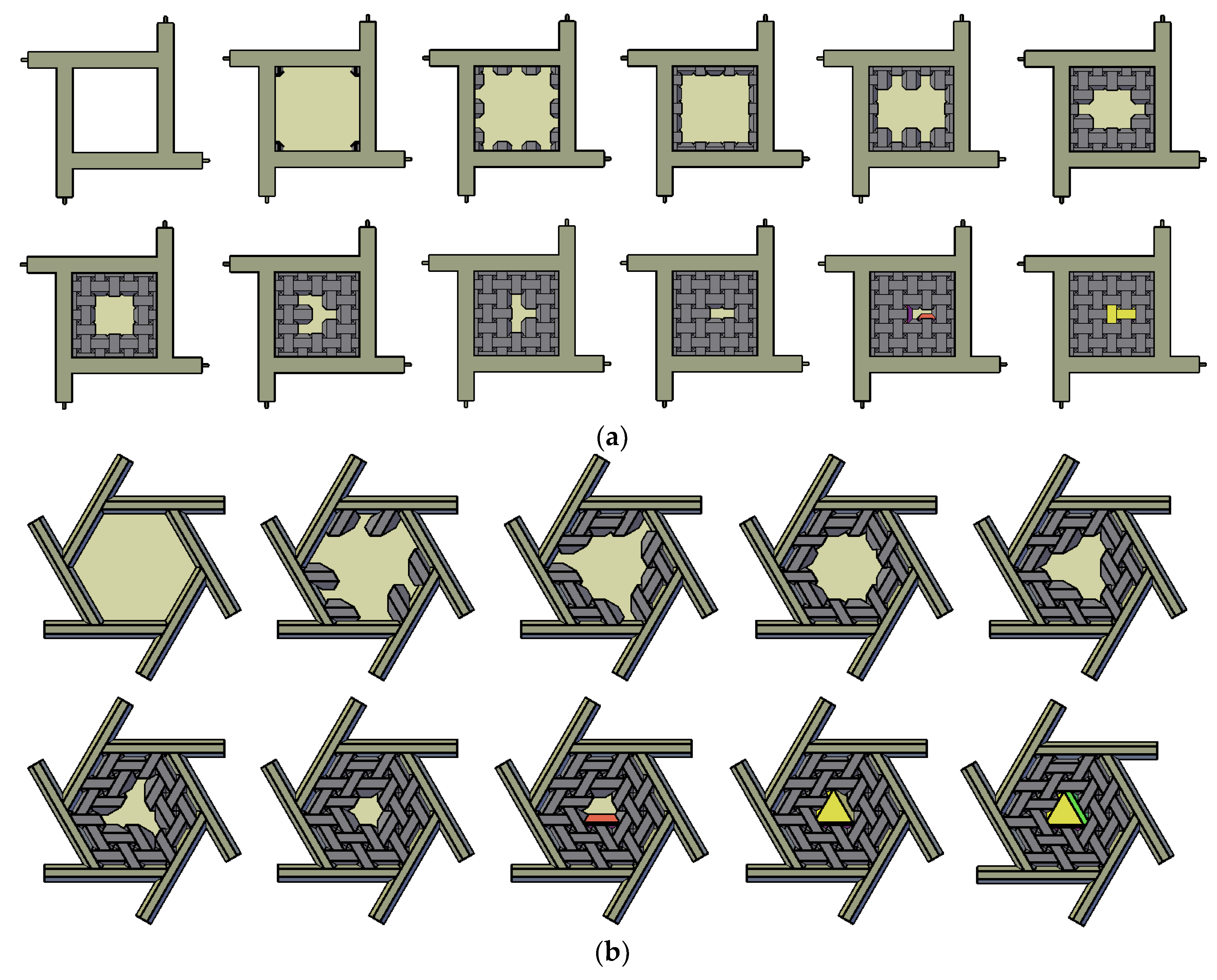
Figure 23a illustrates the order in which the prefabricates are laid in a square field. Constructing the grillage from I-beams is not a mistake, as individual prefabs can be slipped under the upper flanges of the beams. Figure 23b illustrates the order in which rhombic prefabs are laid in a hexagonal field. This grillage is made of beams with hexagonal cross-sections, and the slabs are relief on both sides. The order in which the prefabs are laid depends neither on the beam cross-sections nor the type of top and bottom surface of the slab.
Slabs made of topologically blocking prefabs are tight; that is, no gaps are allowed between the components. This means that the real dimensions of the components should be equal to their modular dimensions, as a slab composed of components of smaller dimensions would be damaged after removal of the temporary scaffold (or, at least, it would be excessively deflected). Realization of a slab from components with real dimensions larger than the modular ones is not possible at all.
The inability to tolerate the dimensions of the components is not an obstacle to the construction of the slabs, provided that the assembly is carried out in the correct order and the components are suitably shaped. As it is not possible to insert the components vertically from above (due to the inclination of the faces), the faces should be slipped in horizontally. Their side edges will come into point contact during assembly (Figure 24a); such contact may be eliminated by chamfering the edges (Figure 24b). In this case, the distance between the components will be maintained during fitting; however, this will not adversely affect the conditions of their mutual touching after the assembly finishes. The only drawback will be loss of the full tightness of the slab (i.e., the presence of holes of dimensions defined by the edge chamfer). In the case of one-side smooth slabs, sliding the prefabricates does not cause complications; that is, during the whole process, the distance between the sliding component and the components in the final position is maintained (Figure 25).
A different situation applies to both sides smooth slabs. Regardless of the component dimensions, some of its faces will always be vertical and, so, it is important that the faces of the component currently moved are not parallel to the faces of the components already installed, as this causes contact over the whole faces of the components (Figure 26a). Practically, the measures of angles marked in red in Figure 13a,b and the values of the parameter amax, defined by Formulas (9) and (10), must satisfy the sharp inequalities. In this case, sliding is carried out while maintaining distance until the component reaches its destination (Figure 26b).
4.4. Shaping the Keystones
The number of components that cannot be wholly inserted into the structure (and, thus, which must be divided into parts) depends on the upper and lower surface types of the slab, as well as the inclination of the side faces. The conditions set out in Figure 23a,b should be regarded as extremely favourable. Cross-sections of these parts of the square slab, which are designed to be introduced first (marked in red and with numbers 1 and 3 in Figure 27), should be trapezoidal or, in extreme cases, triangular. The angle θ1, which is the inclination of the plane dividing the component to the horizontal plane, should be smaller than the angle θ of inclination of the side faces of the component to this plane. As the shapes of the components are different for slabs with diverse top and bottom surfaces (rough or smooth), the detailed dimensions of the individual parts of the keystone are also classified according to this factor.
The division of keystones intended for square slabs of particular types are shown in Figure 28. Each of the keystones is defined by the dimensions asi and bsi, which essentially define the shape of a typical component of the slab and the dimension csi that sets the maximum width of the shorter base of the trapezium (i.e., the cross-section of this part of keystone), which should be introduced first. These dimensions have been calculated as a function of the following variables: m, which defines the dimension of the mesh, and t, which denotes the thickness of the slab; these are treated as the input parameters.
A keystone for a double-sided rough slab is shown in Figure 28a, with dimensions defined by Equations (11)–(13); one for a slab smooth from above and rough from below in Figure 28b, defined by Equations (14)–(16); one for a slab rough from above and smooth from below in Figure 28c, defined by Equations (14), (15) and (17); and one for a slab with both sides smooth and a grid of squares on the surface from the bottom in in Figure 28d, defined by Equations (18)–(20). The construction of a two-sided smooth slab in which the grid of squares is on the upper surface of the slab is not possible at all. In this case, there is no possibility of inserting any part of the component through the hole, whose dimension is equal to the dimension of the sliding component along only one straight line.
Designing a keystone for hexagonal and triangular slabs is theoretically possible in two ways. Each of the three rhombic components, which together are equivalent to a hexagonal component, can be divided into two parts, in analogy to a keystone for the square slab; alternatively, the hexagonal component can be divided into three parts. The first solution, in which the total number of elements constituting the keystone is twice as large as in the second solution, will be omitted, and the further description will concern shaping a hexagonal keystone composed of three elements.
The division of hexagonal keystones intended for triangular and hexagonal slabs, the particular types differing with the external surface, and the order of inserting them into the vault are shown in Figure 29. The parts of the keystones have been described in a similar way as the keystones for square vaults. The parameters ahi and bhi refer to the dimensions of the whole component, while chi and dhi describe the maximum dimensions of the cross-sections of these parts in the divided component, which should be entered, respectively, first and second. All mentioned dimensions have been calculated as a function of the following variables: m, which defines the dimension of the mesh, and t, which denotes the thickness of the slab; both of which are the input parameters.
A hexagonal keystone for a double-sided rough slab is shown in Figure 30a, with dimensions as defined by Equations (21)–(24); one for a slab smooth from above and rough from below in Figure 30b, defined by Equations (25)–(28); one for a slab rough from above and smooth from below in Figure 30c, defined by Equations (25), (26) and (29); one for a slab with both sides smooth and with a grid of hexagons on the bottom surface in Figure 30d, defined by Equations (25), (26) and (30); and one for a slab with both sides smooth and with a grid of hexagons on the upper surface in Figure 30e, defined by Equations (25), (26) and (31).
5. Summary
The principles formulated in the article outline a framework providing the ability to aggregate slabs from interlocking components of small size. The condition for success in implementing this system for practical applications lies in the development of production technologies for prefabricates, which must be characterized by higher strength and hardness than the existing precast concrete and ceramic products, but which have smaller mass. Some important problems that this technology has to address are: providing prefab edges which are resistant to damage during transport and assembly, and faces with good smoothness, as the effectiveness of the topological blocking of components depends largely on the quality of the contacting surfaces. There are high hopes in this area, due to the development of 3D printing technology.
The specific benefits that can be seen with the implementation of this system are manifold. The concept presented in the paper allows for the use of the same components to construct floor slabs of various dimensions and even load capacities, thanks to the ability to co-operate with structural grillages. The construction of a slab from small-sized elements simplifies assembly, which can be performed by less-qualified personnel and without the use of specialized equipment, as well as under difficult access conditions. The need to use a structural support at the time of construction weakens the resulting quality only to a small extent. The realization of a floor slab does not require the use of technological water, nor does it cause the permanent integration of components; instead, it creates favourable circumstances for quick dismounting, as well as the recovery of structural elements and their re-use.
The last, but not least, aspect of the construction of slabs from topologically interlocking prefabs is aesthetics. The floor slabs that are made in a single layer (i.e., without layers covering the floor or the ceiling) are extremely decorative. Strengthening of the aesthetic value may be obtained by diversification of the material from which the individual components are produced (e.g., in terms of colour). There is also the theoretical opportunity to create a slab from only keystone elements, which will allow the replacement of any element of the slab without the need to dismantle it, only requiring temporary local support.
As the replacement of individual components is possible without the deconstruction of the entire slab, there are possibilities not only for the quick removal of any damage, but also to change the appearance of an architectural object during its life cycle. Due to the fact that these values referring to aesthetic criteria are available on the condition of depriving the slab of cladding layers, this circumstance contributes, to a certain extent, to a weakening of the rationality of applying technology in general construction, in favour of its implementation in objects that can qualify as unique architecture.
Funding
This research received no external funding.
Conflicts of Interest
The author declares no conflict of interest.
References
- Addis, B. 3000 Years of Design Engineering and Construction; Phaidon Press Limited: London, UK, 2007. [Google Scholar]
- Gallon, M. Machines et Inventions Approuvees par L’Academie Royale des Sciences; Martin-Coignard-Guerin: Paris, France, 1735. [Google Scholar]
- Frezier, A.F. La Théorie et la Pratique de la Coupe des Pierres et des bois Pour la Construction des Voutes et Autres Parties des Bâtiments Civils et Militaires. Tome 2; Libraire du Roi: Paris, France, 1737. [Google Scholar]
- Wallis, J. Opera Mathematica; E Theatro Sheldaniano: Oxford, UK, 1695. [Google Scholar]
- Rabasa Diaz, E. La boveda plana de Abeille en Lugo. In Actas del Segundo Congreso Nacional de Historia de la Construccion; Bores, F., Fernandez, J., Huerta, S., Rabasa, E., Eds.; Universidad de la Coruna: A Coruna, Spain, 1998; pp. 409–415. [Google Scholar]
- Nichilo, E. Learning from stone traditional vaulted systems for the contemporary project of architecture. The experimental construction site at the Ponton de la Oliva (Spain, 1851–1858): Survey of the small «boveda plana» of the Casa de Mina de Limpia, and reconstructive hypothesis for the Casa del Guarda flat-vault. In Proceedings of the First International Congress on Construction History; Huerta, S., Ed.; Juan de Herrera, SEdHC, ETSAM, A.E. Benvenuto, COAM, F. Dragados: Madrid, Spain, 2003; pp. 743–754. [Google Scholar]
- Guijarro, I.L. Estudio del comporamento structural de la boveda plana en la “Casa de Mina de Limpia” (Ponton de la Oliva). Master’s Thesis, Esquela Tecnica Superior de Ingenieros de Caminos, Canales y Puertos, Universidad Politecnica de Madrid, Madrid, Spain, 2016. [Google Scholar]
- Dyskin, A.V.; Estrin, Y.; Kanel-Belov, A.J.; Pasternak, E. A new Concept in Design of Materials and Structures: Assemblies of Interlocked Tetrahedron-Shaped Elements. Scr. Mater. 2001, 44, 2689–2694. [Google Scholar] [CrossRef]
- Dyskin, A.V.; Estrin, Y.; Kanel-Belov, A.J.; Pasternak, E. Topological Interlocking of Platonic Solids: A Way to New Materials and Structures. Philos. Mag. Lett. 2003, 83, 197–203. [Google Scholar] [CrossRef]
- Brocato, M.; Mondardini, L. Parametric analysis of structures from flat vaults to reciprocal grids. Int. J. Solids Struct. 2015, 54, 50–65. [Google Scholar] [CrossRef]
- Weizmann, M.; Amir, O.; Grobman, Y.J. Topological interlocking in architecture: A new design method and computational tool for designing building floors. Int. J. Archit. Comput. 2017, 15, 107–118. [Google Scholar] [CrossRef]
- Sakarovitch, J. Construction History and Experimentation. In Proceedings of the Second International Congress on Construction History, Cambridge, UK, 29 March–2 April 2006; Dunkeld, M., Cambell, J., Louw, H., Tutton, M., Addis, B., Thone, R., Eds.; Queens College: Cambridge, UK, 2006; pp. 2777–2791. [Google Scholar]
- Fleury, F. Evaluation of the Perpendicular Flat Vault Inventor’s Intuitions through Large Scale Instrumented Testing. In Proceedings of the Third International Congress on Construction History, Cottbus, Germany, 20–24 May 2009; Kurrer, K.E., Lorenz, W., Eds.; BTU: Cottbus, Germany, 2009; pp. 611–618. [Google Scholar]
- Fallacara, G. Towards a Stereotomic Design: Experimental Constructions and Didactic Experiences. In Proceedings of the Third International Congress on Construction History, Cottbus, Germany, 20–24 May 2009; Kurrer, K.E., Lorenz, W., Eds.; BTU: Cottbus, Germany, 2009; pp. 553–560. [Google Scholar]
- Ettlin, R.; Fallacara, G.; Tamborero, L. Plaited Stereotomy. Stone Vaults for the Modern World; ARACNEditrice S.r.l: Rome, Italy, 2008. [Google Scholar]
- Fallacara, G. Stereotomy. Stone Architecture and New Research; Presses Ponts et Chaussées: Paris, France, 2012. [Google Scholar]
- Brocato, M.; Mondardini, L. Geometric methods and computational mechanics for the design of stone domes based on Abeille’s bond. In Advances in Architectural Geometry; Ceccato, C., Hesselgren, L., Pauly, M., Pottmann, H., Wallner, J., Eds.; Springer: Wien, Austria, 2010; pp. 149–162. [Google Scholar]
- Brocato, M.; Mondardini, L. A new type of stone dome based on Abeille’s bond. Int. J. Solids Struct. 2012, 49, 1786–1801. [Google Scholar] [CrossRef] [Green Version]
- Grillanda, N.; Chiozzi, A.; Bondi, F.; Tralli, A.; Manconi, F.; Stochino, F.; Cazzoni, A. Numerical insights on the structural assessment of historical masonry stellar vaults: The case of Santa Maria del Monte in Cagliari. Contin. Mech. Thermodyn. 2019, in press. [Google Scholar] [CrossRef]
- Miodragovic Vella, I.; Kotnik, T. Geometric Versatility of Abeille Vault. A Stereotomic Topological Interlocking Assembly. In Proceedings of the eCAADe 2016 Conference, Oulu, Finland, 22–26 August 2016; Herneoja, A., Österlund, T., Marklanen, P., Eds.; Oulu School of Architecture: Oulu, Finland, 2016; pp. 391–397. [Google Scholar]
Figure 1.
Flat vaults: (a) of Abeille (1699); (b) of Truchet (1699); and (c,d) of Frezier (1735).

Figure 2.
The procedure of modeling a vault component based on a square: (a) establishment of a grid of squares σ4 and insertion the planes α4j perpendicular to it; (b) rotations of the planes α4j; (c) final determination of a component shape with the use of planes β1 and β2.
Figure 2.
The procedure of modeling a vault component based on a square: (a) establishment of a grid of squares σ4 and insertion the planes α4j perpendicular to it; (b) rotations of the planes α4j; (c) final determination of a component shape with the use of planes β1 and β2.

Figure 3.
The procedure of modeling a vault component based on a regular hexagon: (a) establishment of a grid of hexagons σ6 and insertion the planes α6j perpendicular to it; (b) rotations of the planes α6j; (c) final determination of a component shape with the use of planes β1 and β2.
Figure 3.
The procedure of modeling a vault component based on a regular hexagon: (a) establishment of a grid of hexagons σ6 and insertion the planes α6j perpendicular to it; (b) rotations of the planes α6j; (c) final determination of a component shape with the use of planes β1 and β2.

Figure 4.
The procedure of modeling a vault component based on a rectangular triangle: (a) establishment of a grid of triangles σ3 and insertion the planes α3j perpendicular to it; (b) rotations of the planes α3j; (c) final determination of a component shape with the use of planes β1 and β2, (d) cutting off excess component volume using a plane β3.

Figure 5.
The procedure of modeling a vault component based on a rhombus β1: (a) establishment of a grid of rhombuses σ4 and insertion the planes α4j perpendicular to it; (b) rotations of the planes α4j; (c) final determination of a component shape with the use of planes β1 and β2.
Figure 5.
The procedure of modeling a vault component based on a rhombus β1: (a) establishment of a grid of rhombuses σ4 and insertion the planes α4j perpendicular to it; (b) rotations of the planes α4j; (c) final determination of a component shape with the use of planes β1 and β2.

Figure 6.
Stabilization of a triangular component depending on its orientation in space and location in the slab: (a) stable component; (b) unstable component; and (c) stabilization with additional support.
Figure 6.
Stabilization of a triangular component depending on its orientation in space and location in the slab: (a) stable component; (b) unstable component; and (c) stabilization with additional support.

Figure 7.
Slabs composed from hexagonal and triangular components: (a) triangular; (b) hexagonal.


Figure 8.
Hexagonal slabs composed of rhombic components: (a) joined three into hexagonal sets; (b) shaped analogically to a square vault.
Figure 8.
Hexagonal slabs composed of rhombic components: (a) joined three into hexagonal sets; (b) shaped analogically to a square vault.

Figure 9.
Slabs composed of rhombic and triangular components: (a) triangular; (b) hexagonal.

Figure 10.
Hexagonal slabs composed of hexgonal and rhombic components.

Figure 11.
Modeling of one-sided smooth components based on: (a) a regular hexagon; (b,c) an equilateral triangle; and (d,e) a rhombus.
Figure 11.
Modeling of one-sided smooth components based on: (a) a regular hexagon; (b,c) an equilateral triangle; and (d,e) a rhombus.

Figure 12.
Triangular and hexagonal slab structures inspired by Abeille vaults.

Figure 13.
Dimensional restrictions in triangular components inspired by Frezier blocks.

Figure 14.
Double-sided smooth vault components based on an equilateral triangle, a regular hexagon, and a rhombus, inspired by Frezier blocks: (a) of the first type; and (b) of the second type.
Figure 14.
Double-sided smooth vault components based on an equilateral triangle, a regular hexagon, and a rhombus, inspired by Frezier blocks: (a) of the first type; and (b) of the second type.

Figure 15.
Triangular and hexagonal slab structures inspired by Frezier blocks.

Figure 16.
Protection of the slab against the action of the thrust force by means of a steel frame.

Figure 17.
Constructing a grillage from rectangular pipes with flat bars attached to the bottom face.
Figure 17.
Constructing a grillage from rectangular pipes with flat bars attached to the bottom face.

Figure 18.
Linking the vaults with a beam grids, based on coincidence of the modular planes with: (a) the center planes of the beams, or (b) planes containing the sides of the beams.
Figure 18.
Linking the vaults with a beam grids, based on coincidence of the modular planes with: (a) the center planes of the beams, or (b) planes containing the sides of the beams.

Figure 19.
Co-operation between the flat vault and a grillage made of hexagonal pipes.

Figure 20.
The vaults filling square fields in grillages from beams with vertical faces: (a) both sides rugged; (b) one side smooth; and (c) both sides smooth.
Figure 20.
The vaults filling square fields in grillages from beams with vertical faces: (a) both sides rugged; (b) one side smooth; and (c) both sides smooth.

Figure 21.
One-sided smooth vault from components enlarged by a layer of constant thickness.

Figure 22.
Triangular and hexagonal slabs well-fitting to vertical faces of beams: (a) both sides rugged; (b) one side smooth; and (c) both sides smooth.
Figure 22.
Triangular and hexagonal slabs well-fitting to vertical faces of beams: (a) both sides rugged; (b) one side smooth; and (c) both sides smooth.

Figure 23.
Order of laying prefabs: (a) in a square field; and (b) in a hexagonal field.

Figure 24.
Sliding the components into place in a both sides rugged vault: (a) a components with non-chamfered edges; and (b) components with chamfered edges.
Figure 24.
Sliding the components into place in a both sides rugged vault: (a) a components with non-chamfered edges; and (b) components with chamfered edges.

Figure 25.
Sliding the components into place in a one-side smooth vault.

Figure 26.
Sliding the components into place in a both sides smooth vault if the planes containing the side faces of the components are: (a) parallel; (b) intersecting.
Figure 26.
Sliding the components into place in a both sides smooth vault if the planes containing the side faces of the components are: (a) parallel; (b) intersecting.

Figure 27.
The order of entering parts of the keystone into the square vault.

Figure 28.
Dimensions of the parts of the keystone for use in square vaults: (a) rough on both sides; (b) smooth from above; (c) smooth from below; and (d) both sides smooth.
Figure 28.
Dimensions of the parts of the keystone for use in square vaults: (a) rough on both sides; (b) smooth from above; (c) smooth from below; and (d) both sides smooth.


Figure 29.
The order of entering parts of hexagonal keystones into the vault: (a) rough on both sides; (b) smooth from above; (c) smooth from below; and (d,e) both sides smooth.
Figure 29.
The order of entering parts of hexagonal keystones into the vault: (a) rough on both sides; (b) smooth from above; (c) smooth from below; and (d,e) both sides smooth.

Figure 30.
Dimensions of the parts of the hexagonal keystones for use in triangular and hexagonal vaults: (a) rough on both sides; (b) smooth from above; (c) smooth from below; and (d,e) both sides smooth.
Figure 30.
Dimensions of the parts of the hexagonal keystones for use in triangular and hexagonal vaults: (a) rough on both sides; (b) smooth from above; (c) smooth from below; and (d,e) both sides smooth.

© 2020 by the author. Licensee MDPI, Basel, Switzerland. This article is an open access article distributed under the terms and conditions of the Creative Commons Attribution (CC BY) license (http://creativecommons.org/licenses/by/4.0/).
Share and Cite
MDPI and ACS Style
Piekarski, M. Floor Slabs Made from Topologically Interlocking Prefabs of Small Size. Buildings 2020, 10, 76. https://doi.org/10.3390/buildings10040076
AMA Style
Piekarski M. Floor Slabs Made from Topologically Interlocking Prefabs of Small Size. Buildings. 2020; 10(4):76. https://doi.org/10.3390/buildings10040076
Chicago/Turabian StylePiekarski, Maciej. 2020. "Floor Slabs Made from Topologically Interlocking Prefabs of Small Size" Buildings 10, no. 4: 76. https://doi.org/10.3390/buildings10040076
Note that from the first issue of 2016, this journal uses article numbers instead of page numbers. See further details here.