Article

Experimental Study of Thermal Buoyancy in the Cavity of Ventilated Roofs

1
SINTEF Community, 7046 Trondheim, Norway
2
Department of Architecture and Civil Engineering, Chalmers University of Technology, SE-412 96 Gothenburg, Sweden
3
Department of Civil and Environmental Engineering, Norwegian University of Science and Technology, 7491 Trondheim, Norway
*
Author to whom correspondence should be addressed.
Buildings 2020, 10(1), 8; https://doi.org/10.3390/buildings10010008
Submission received: 7 October 2019 / Revised: 3 December 2019 / Accepted: 4 December 2019 / Published: 7 January 2020
(This article belongs to the Section Building Energy, Physics, Environment, and Systems)

Abstract

:
Pitched wooden roofs are ventilated through an air cavity beneath the roofing in order to remove heat and moisture from the roof construction. The ventilation is driven by wind pressure and thermal buoyancy. This paper studies ventilation driven by thermal buoyancy in the air cavity of inclined roofs. The influence of air cavity design and roof inclination on the airflow is investigated. Laboratory measurements were carried out on an inclined full-scale roof model with an air cavity heated on one side in order to simulate solar radiation on a roof surface. Equipment to measure temperature was installed in the roof model, while air velocity in the cavity was determined by smoke tests. Combinations of different roof inclinations, air cavity heights and applied heating power on the air cavity top surface were examined. The study showed that increased air cavity height led to increased airflow and decreased surface temperatures in the air cavity. Increased roof inclination and heating power applied to the roofing also increased the airflow. The investigations imply that thermal buoyancy in the air cavity of pitched roofs could be a relevant driving force for cavity ventilation and important to consider when evaluating the heat and moisture performance of such a construction.

1. Introduction

1.1. Pitched Wooden Roofs

Pitched wooden roofs, defined as pitched roofs with a wooden load-bearing structure [1], are traditionally and widely used on small-scale buildings in Nordic countries. The use of wooden roofs poses certain challenges, as building envelopes are subject to large weather strains and related damage risks [2]. To ensure their durability, pitched roofs are designed to be naturally ventilated by allowing air to flow through an air cavity beneath the roofing. This ventilation is essential for removing moisture and heat from the roof construction, which is necessary to avoid damage and durability problems [1].
In Norway, removal of excessive heat from the roof construction has traditionally been needed to reduce snowmelt on the roof during winter, e.g., as studied by Blom [3,4]. With the introduction of building integrated photovoltaics (BIPV) on roofs, decreased efficiency of these due to overheating has become a concern. Consequently, BIPV on inclined roofs are often constructed as ventilated roofs with an air cavity beneath the panels [5,6]. In addition, the increasing focus on CO2-emissions from buildings and the favourable carbon footprint of wood make wooden roofs attractive to use in a growing number of buildings. The use of pitched wooden roofs on larger building structures with longer roof spans has been introduced, further underlining the complexity as well as the need for ventilation.
The use of air layers in building envelopes, including ventilated cavities in roofs, is summarized by Zhang et al. [7], while general recommendations concerning construction of pitched roofs are presented by Roels and Langmans [8]. Specific guidelines for construction and ventilation of pitched wooden roofs in Norway are given in Bøhlerengen [9,10]. Among others, the guidelines present recommendations regarding the height of the ventilated cavity, depending on the type of roof structure, the length of the roof and the roof inclination. The Norwegian guidelines are valid for roofs with an inclination larger than 10–15° and a span less than 15 m. Larger spans, low-pitched roofs and BIPV are not covered but are currently attractive to use. Understanding the performance of such roofs as well as development of the guidelines is highly dependent on proper understanding of the physical behaviour of the airflow beneath the roofing.

1.2. Driving Forces

The driving forces inducing the airflow through the air cavity are identified as wind pressure and thermal buoyancy. Wind exposure and wind as the driving force for air cavity ventilation have been treated in several studies, including in the Norwegian context [11]. Through field tests on attic ventilation, Walker and Forest [12] found that wind pressure was the dominating driving force for roof ventilation. However, Falk and Sandin [13] observed that wind-induced airflow in a vertical ventilated cavity was suppressed when a large buoyancy-induced airflow was present. In addition, when wind is not present, or wind speeds are low, the ventilation is dependent on thermal buoyancy in order to function.
Comparatively little seems to have been written on thermal buoyancy within the given context. Contributions have been made, especially in the field of theoretical analyses [14,15,16,17,18,19,20,21,22]. Computational fluid dynamics (CFD) was used in many of the analyses to predict the temperature and velocity of the airflow in ventilated roofs. In addition, some authors have aimed at experimentally validating their numerical simulations. This has shown that buoyancy-driven ventilation is dependent on the choice and design of roofing [23] and the inclination of the roof and height of the air cavity [24,25]. Most of the cited research has been concerned with investigating challenges particular to temperate or warm climates through numerical studies. Therefore, most attention has been given to the cooling effect of buoyancy-driven airflows in roofs. As a result, the air cavities investigated differ from what is common in Nordic countries.

1.3. Previous Research

Thermal buoyancy in inclined, rectangular channels with open ends has also been the subject in experimental studies. The main centres of interest have been air cavities in pitched roofs, solar air collectors and cavities beneath BIPV.
Hofseth [26] measured the velocity of buoyancy-driven air flows in an inclined air cavity by using smoke tests. However, the roof inclination and cavity height were kept constant during all measurements. The influence of inclination on the air velocity was investigated by Susanti et al. [27], who observed that decreased inclination gave a reduction in velocity. The air velocity was also reduced when cavity temperatures decreased. Temperature conditions was further studied by Lee et al. [28] and Chami and Zoughaib [29]. The temperature difference between the heated surface and the air in the cavity was found to increase with roof inclination [28]. Chami and Zoughaib [29] observed that a reduction in the mean temperatures on the surfaces of the cavity decreased the airflows through the cavity. Airflow in the cavity of low-pitched roofs in particular was examined by Nusser and Teibinger [30], who investigated the relationship between roof inclination, air cavity height and resulting airflow in the cavity.
Experimental studies have also been performed to analyse thermal buoyancy in solar air collectors, by experiments on inclined channels heated from the top [27,31,32,33,34]. Bunnag et al. [33] observed that increased roof inclination decreased cavity temperatures significantly, while air velocity increased. Zhai et al. [34] found that air temperatures increased in the flow direction and that temperature distribution across the channel was not uniform.
Research on ventilation of photovoltaics (PV) [35] resulted in air velocity profiles in an air cavity as a function of heat input. However, the work focused on façades and did not include roof constructions. Few studies on ventilation of BIPV roofs in the Nordic climate have been found. One study from Sweden [31] treated buoyancy-driven ventilation behind PV panels on roofs and presented velocity and temperature profiles for the air cavity behind the panels. However, the study did not provide conclusive recommendations for design of the air cavity.

1.4. Knowledge Gap

Several studies on the topic of heat transfer and thermal buoyancy in rectangular cavities have been performed. However, a review of the literature reveals knowledge gaps on the subject of air cavity design in cold climates. To the authors’ knowledge, most air cavity heights previously studied are larger than what is traditionally used in Scandinavian roofs. In addition, most research involve steep roofs and a limited number of inclinations. Furthermore, the examined temperature levels in experiments correspond to warm climates. The research presented in this paper is performed in order to evaluate the relationship between buoyancy-driven airflow and air cavity design in the Nordic context.

1.5. Objectives and Scope

The present study experimentally investigates airflow driven by thermal buoyancy in the air cavity beneath the roofing in inclined roofs. The laboratory model developed and previously studied by Gullbrekken et al. [36] is used. The main goal is to examine how the air flow is influenced by temperature conditions and air cavity design, as is typical for the Nordic context. A central objective is that experimental investigations of this study could contribute to the development of numerical models for simulation of air flows in cavities with different designs. The following research questions are addressed:
  • How are the temperature conditions in the air cavity related to the air cavity design?
  • How is the airflow through the cavity influenced by the air cavity design?
  • To what degree may thermal buoyancy drive airflow in the air cavity?
In the present study, air cavity design includes air cavity height and air cavity inclination. The scope of this study only includes insulated pitched wooden roofs, i.e., inclined air cavities. Cold attics thus fall outside the subject matter analysed. In addition, the influence of roofing design, underlayer roof material, tile batten design, ridge and eaves design, and cross ventilation is not considered. Only heating of the roofing is studied. Hence, undercooling in the air cavity compared to the ambient air and heating of the cavity due to heat transmission through the roof construction from the inside are not considered.
Furthermore, the results presented in this paper constitute a simplification of the building physics encountered. Incompressible and laminar flow is assumed, and average air velocity is approximated in the theoretical evaluation. In addition, the calculation of driving force caused by thermal buoyancy is simplified, including an assumption of constant air temperature in the cross section of the cavity.

2. Theoretical Framework

In order to address the research questions, an outline of fundamental physics related to thermal buoyancy is presented. The airflow through the cavity beneath the roofing in ventilated roofs is dependent on the driving forces and flow resistances present. Various expressions describing the relationship between these two forces exist. Equation (1) is presented by Hagentoft [37].
V ˙ = Δ P S
where V ˙ (m3/s) is the airflow, ΔP (Pa) is the driving force and S (Pa/(m3/s)) is the flow resistance. The airflow may be further described by established principles from fluid mechanics, as studied by Kronvall [38]. The fluid mechanics theory applied in the present study is valid if incompressible and laminar flow is assumed. Given the physical conditions present in building applications, negligible error is associated with assuming that air and water vapour are ideal gases, hence incompressible [39]. The Reynolds number, Re (-), used to determine the flow regime in the air cavity, is given by Equation (2) [40].
R e = u a v g · D h ν
where uavg (m/s) is the average velocity of the airflow, Dh (m) is the hydraulic diameter of the cavity and ν (m2/s) is the kinematic viscosity of the air. Given laminar flow in wide rectangular cavities, uavg may be approximated to 0.67⋅umax, where umax is the maximum velocity of the airflow [41]. Below a critical value of the Reynolds number, Recrit, the airflow is laminar. Recrit typically appears in the interval 2000–2500 [38]. The transitional flow regime describes the changeover from laminar to turbulent flow, where fully turbulent flow often occurs at Re > 4000.
Thermal buoyancy in a cavity is a result of temperature difference and height difference between the inlet and outlet of the cavity. If the air temperature in the cavity is considered constant, the thermal driving force, ΔPT (Pa), is given by Equation (3). Normally, the temperature, and consequently the density, of the air in the cavity varies. In this case, the driving force must be determined by integration from the inlet to the outlet, as given by Equation (4) [42]. If the air cavity can be divided into a finite number of sections, each with an assumed constant temperature, the driving force may be calculated with Equation (5).
Δ P T = ( ρ a ρ c a v i t y ) · g · H
Δ P T = ρ a · g · H g · i n l e t o u t l e t ρ ( h ) d h
Δ P T = ρ a · g · H g · i = 1 n ρ i 1 , i · ( h i h i 1 )
where ρa and ρcavity (kg/m3) are the densities of the surrounding air and cavity air, respectively, g (m2/s) is the gravitational acceleration, and H [m] is the height difference between the inlet and outlet of the air cavity. The density of humid air is given by Equations (6) and (7) [43].
ρ = p a R a · T + p v R v · T
p v = R H · 6.1078 · 10 7.5 · T c T
where pa (Pa) is the partial pressure of dry air (101,325 Pa at ground level), Ra (J/kg K) is the specific gas constant for dry air (287.058 J/kg⋅K), T and Tc are the temperature in K and °C, respectively, pv (Pa) is the pressure of water vapour, Rv (J/kg⋅K) is the specific gas constant for water vapour (461.495 J/kg⋅K), and RH (-) is the relative humidity.
The temperature of the cavity air is affected by heat exchange between the cavity air and the cavity surfaces, and depend on temperature level on the surfaces, air velocity and cavity dimensions. The magnitude of the heat exchange may be described by the characteristic length of the air cavity [43]. The characteristic length characterizes how quickly the temperature of air entering the cavity adjusts towards the effective temperature, T0, which is an upper limit of the temperature in the cavity.

3. Methods

An experimental approach was used in the present study to be able to vary the investigated parameters in a controlled manner. This was important in order to understand the relationship between air cavity design and temperature and flow conditions. In addition, the experimental investigations may form a basis for future numerical modelling.

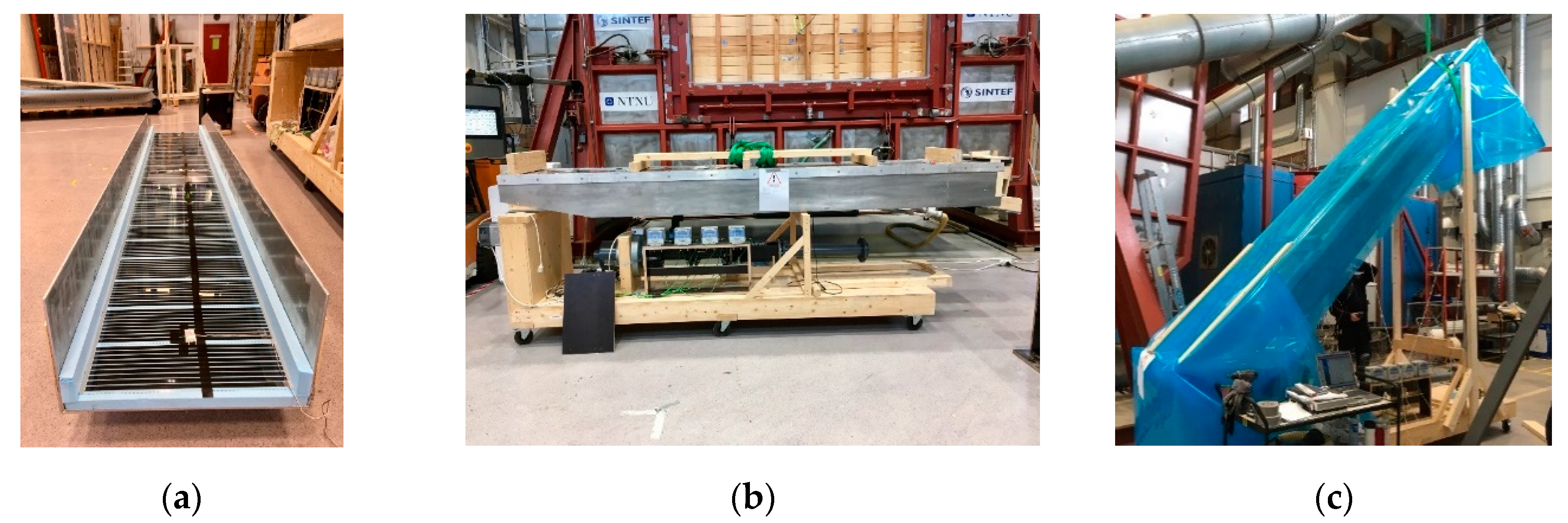
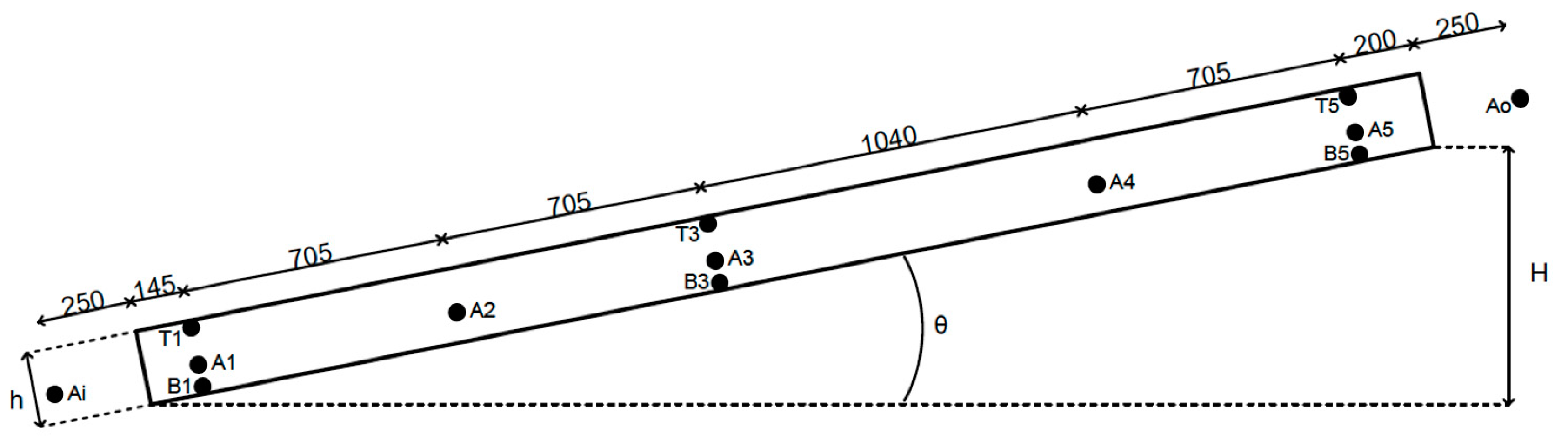
3.1. Laboratory Model

The experimental study was carried out on a laboratory model of an air cavity in a ventilated pitched wooden roof. Figure 1 shows the experimental rig. The model was designed and built by Gullbrekken et al. [36] in the laboratory of SINTEF and NTNU in Trondheim, but modified to carry out the present study. The cavity is constructed as a 3.5 m long, rectangular duct, where an aluminium channel with three faces forms the top and sides of the cavity. The bottom of the cavity is chipboard of 12 mm thickness, mounted on a 200 mm insulated roof construction. The opposing sides of the cavity are open to the laboratory environment and function as the inlet and outlet of the cavity. The cavity has a width of 552 mm, corresponding to the width between 48 mm rafters and counter battens with a centre-to-centre distance of 600 mm. This is a typical design for air cavities in pitched wooden roofs in Norway [1]. The cavity construction is supported by a platform, fixing the air cavity inlet at a constant height. Hinges at the inlet make inclination of the air cavity possible.
The model was initially built to measure local loss coefficients in air cavities [36]. In order to carry out the present study, a heating foil (Flexwatt F40–60 W-230 V, Varmecomfort, Norway) was installed in the top of the cavity to simulate solar radiation on a roof. Electrically conducting heating elements of 13 mm width were spaced 4 mm apart across the foil. A 30 mm layer of extruded polystyrene (XPS) (λ = 0.033 W/(m⋅K)) was mounted between the top of the aluminium channel and the heating foil to limit heat loss through the aluminium (Figure 1a). A layer of 30 mm XPS was for the same reason mounted on each side of the air cavity in the full cavity height, resulting in a cavity width of 492 mm. The heating foil was connected to two serially connected DC voltage controllers (PE 1648 DC power supply 150 V-3 A, Philips, Amsterdam, The Netherlands) to regulate heat power. The DC voltage controllers were chosen to avoid disturbances of the measurements. The roof model was covered by a plastic foil to limit possible influence of air movements in the laboratory air, as shown in Figure 1c.
Temperatures were measured by T-type thermocouples with an accuracy of ±0.5 °C. The thermocouples were calibrated in water before measurements were conducted. Eleven thermocouples were installed inside the cavity for measurement of surface and air temperatures, while ambient temperature was measured with thermocouples located 250 mm from the inlet and outlet. The positions of the thermocouples are described in Figure 2.
The signals from the thermocouples were collected with a data-logger (Expert Key 200 L, Delphin Technology, Bergisch Gladbach, Germany) and sent to a computer for processing. Data was logged with a frequency of 1 Hz. The air velocity in the air cavity was determined by smoke tests, i.e., measurements recording the time required for smoke to travel from the inlet to the outlet of the cavity. In addition, air velocity was measured at the inlet and outlet with an anemometer (SwemaAir 300, Swema, Farsta, Sweden).

3.2. Experimental Procedure

The model was prepared for each test by mounting XPS with the desired air cavity height on each side of the aluminium lid, as shown in Figure 1a. The lid was installed on the model and attached to the rest of the roof construction. In order to improve the airtightness of the model, all connections and joints were sealed with tape [36]. When the cavity was fixed at the desired inclination, experiments were carried out with different power levels at the heating foil.
The data acquisition system was always turned on, including between tests. When the measured temperatures on the top surface of the cavity were stable, a given test run was started. Each test was first run without interruptions for 120 s. The temperatures measured during this period were averaged and used as the temperature at a given measuring point for a given test setup. The relative humidity of the laboratory air was also noted during this period. After 120 s, air velocity through the cavity was determined by smoke tests. Two methods of smoke production were used: (1) A smoke pen with a lit wick and (2) a Dräger tube involving a reaction between air and fuming sulphuric acid. The smoke tests were performed by recording the required time for smoke to travel from the inlet to the outlet of the cavity. Using this test method, it is assumed that the maximum air velocity in the cavity is measured. For each test setup, smoke tests were carried out five times and averaged.

3.3. Test Setups

In order to investigate the influence of the air cavity design on the airflow, the height (h) and inclination (θ) of the air cavity were varied. Air cavity heights and roof inclinations were chosen based on typical roof constructions according to Norwegian building traditions [1]. This included air cavity heights of 23 mm, 36 mm, 48 mm, 70 mm and 140 mm. Cavity height of 140 mm was tested to study the airflow when the cavity is very large compared to traditional solutions. At each given cavity height except 140 mm, cavity inclinations of 5°, 10°, 15°, 30° and 45° with respect to the horizontal plane were studied. At the cavity height of 140 mm, only θ = 30° was tested. Inclinations of 5° and 45° were included in order to compare results with very low or high inclinations. At each combination of air cavity height and inclination, measurements were carried out at four different voltage levels applied to the heating foil (60 V, 120 V, 180 V and 240 V). Voltage level, U (V), and current, I (A), were used to calculate the applied power, Q (W), with resulting heat power levels of 9 W, 36 W, 81 W and 144 W on the heating foil.

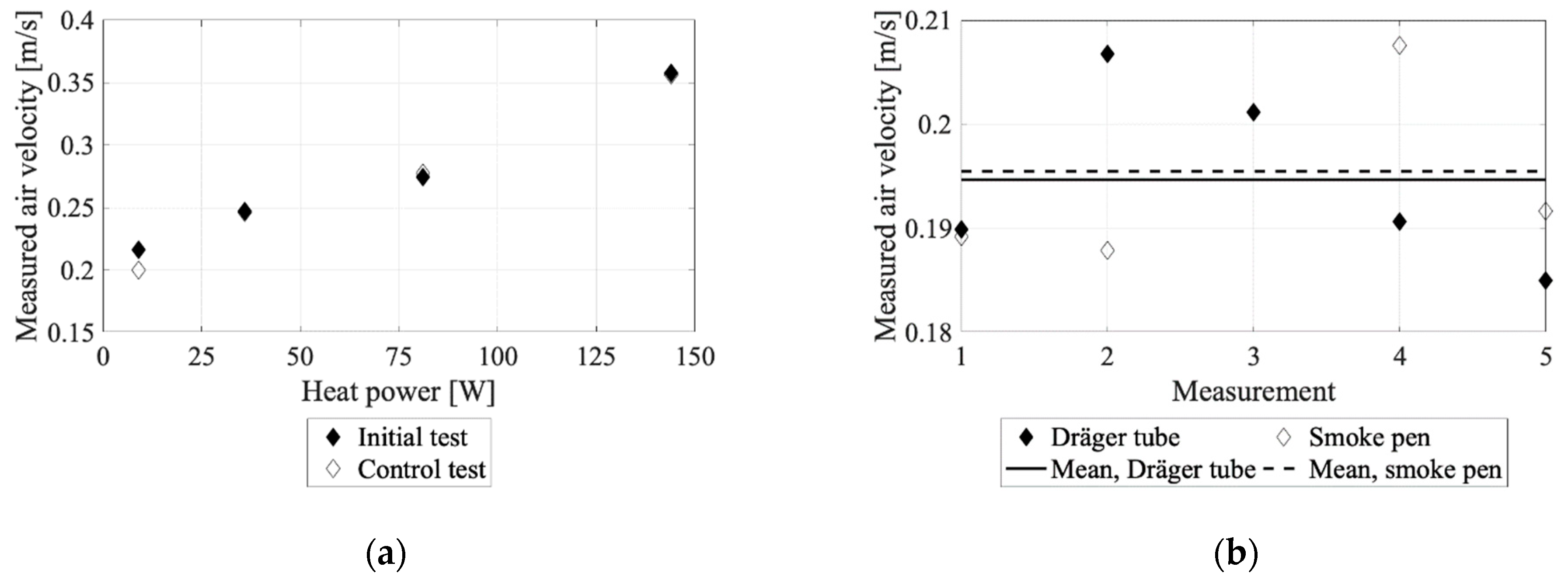
3.4. Validation of Experimental Test Regime

To validate the experimental methods used, one test setup was reproduced eight weeks after the initial tests. The test setup was chosen as h = 48 mm, θ = 15°. Measurements of air velocity and temperatures were performed at all four heat power levels, as carried out in the initial test run. In addition, as two methods of smoke production were employed, a control test comparing the velocity measured using the two methods was performed at h = 48 mm and θ = 15°. As in the initial tests, smoke tests were carried out five times and averaged.
The velocity measurements from validation tests are shown in Figure 3. In Figure 3a, the initial test run at h = 48 mm and θ = 15° is presented together with the control run of this test setup. The validation of the method showed little difference between the initial test and the control test. This indicates little influence from the surroundings on the measurements. Figure 3b compares the two methods used for smoke production. Five measurements and their mean value are presented for each method. The comparison of the methods shows little variation in results, and approximately the same average value for the five measurements.
To fully understand the temperature conditions in the air cavity, different placements of thermocouples on the heating foil were analyzed. Placement completely on, partially on, and between the electrically conducting heating elements of the foil were tested in the middle of the heating foil. Placement completely on conducting elements but on the edges of the heating foil was also included in the analysis.
The results from the measurements are given in Figure 4. The analysis showed similar results if the thermocouples were placed partially or completely on the electrically conducting elements. Placement between the conducting elements gave significantly lower measured surface temperature. The placement of thermocouples was observed to be of larger importance when the applied heating power increased. Measurements on the side edges of the heating foil indicated heat losses through the sides of the cavity model. The analysis implies that the temperature was not uniform on the heated surface of the cavity, which may influence air temperature distributions and flow patterns.

4. Experimental Results

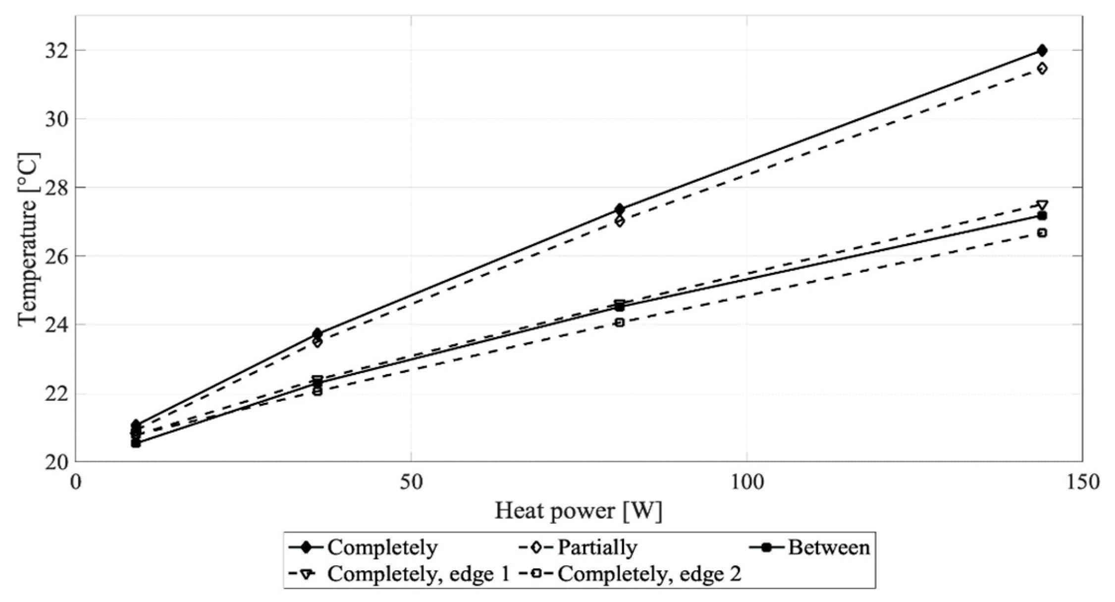
4.1. Temperature Conditions

Results concerning temperature conditions and temperature distribution in the air cavity are presented in this section. Figure 5 gives examples of how the air temperature profile along the cavity from inlet to outlet changed with air cavity height (h) and roof inclination (θ). A complete overview of temperature profiles from all tests is given in Appendix A. The five measuring points of air temperature in the cavity as well as the ambient air temperature at the inlet are included.
To illustrate the temperature profile across the height of the cavity, Figure 6 is presented. A complete overview of temperature profiles from all tests is given in Appendix A. Temperatures on the top and bottom surfaces as well as in the cavity air are included. The figure shows results from measuring point number 3, located 1555 mm from the cavity inlet, as described in Figure 2. The position of the measurement is presented as distance from the bottom unheated surface.

4.2. Air Velocity and Flow Conditions

Measured air velocities at different air cavity heights and roof inclinations are summarized in Figure 7. Note that measured air velocity is the assumed maximum velocity through the air cavity. Also note that no results are given for h = 23 mm at θ = 5° and Q = 9 W and 36 W. Due to very low airflow in these two cases, velocity measurements were unsuccessful. Figure 8 shows measured air velocity (Figure 8a) and calculated airflow rate (Figure 8b) for different air cavity heights at a roof inclination of 30°. The velocity measurements resulted in calculated air change rates (h−1) in the interval 30–400 h−1.
In order to investigate the flow regime, the Reynolds number was calculated by Equation (2) for all different test variations. The results are presented in Figure 9. The Reynolds number for airflows at h = 140 mm, θ = 30° are not shown in Figure 9 but was found to be 3924, 3346, 2851 and 2445 in the case of heat power 9 W, 36 W, 81 W and 144 W, respectively. The critical Reynolds number is assumed to be 2000 [38], i.e., the transitional flow region is represented by the shaded area in Figure 9.

4.3. Driving Force

Thermal driving force (ΔPT) at different roof inclinations, air cavity heights and applied heating power was determined by Equation (5). The calculation takes into account the density decreases of the cavity air as it moves upwards in the cavity. The results are presented in Figure 10. Figure 11a shows the relationship between the thermal driving force and the air cavity height at a roof inclination of 30°. Thermal driving force and airflow rate in the air cavity are presented in Figure 11b. The latter diagram includes results for air cavity heights of 23 mm, 36 mm, 48 mm and 70 mm at all roof inclinations and applied heating powers.

5. Analysis of Measurements

In the present study, ventilation driven by thermal buoyancy in the air cavity of an inclined roof model has been investigated. The research goals include investigation of the temperature distribution in the air cavity, the influence of air cavity design on flow conditions, and investigation of the size of the thermal driving force in the cavity.

5.1. Temperature Conditions

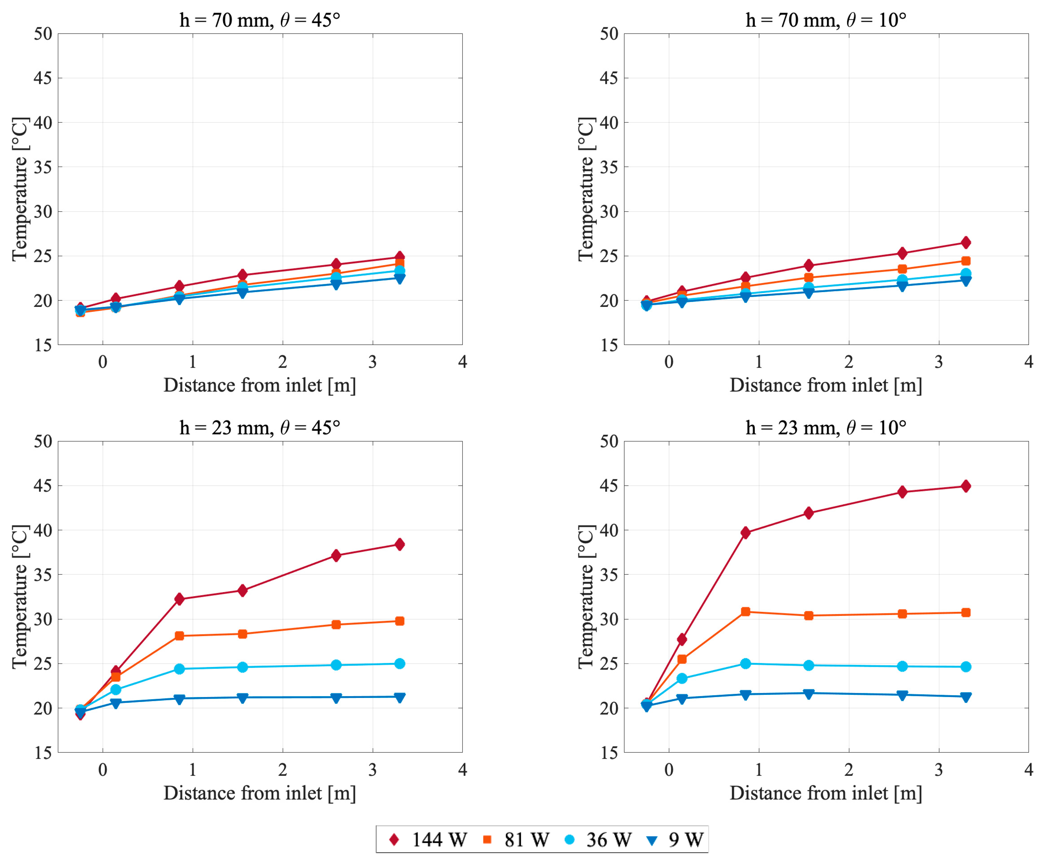
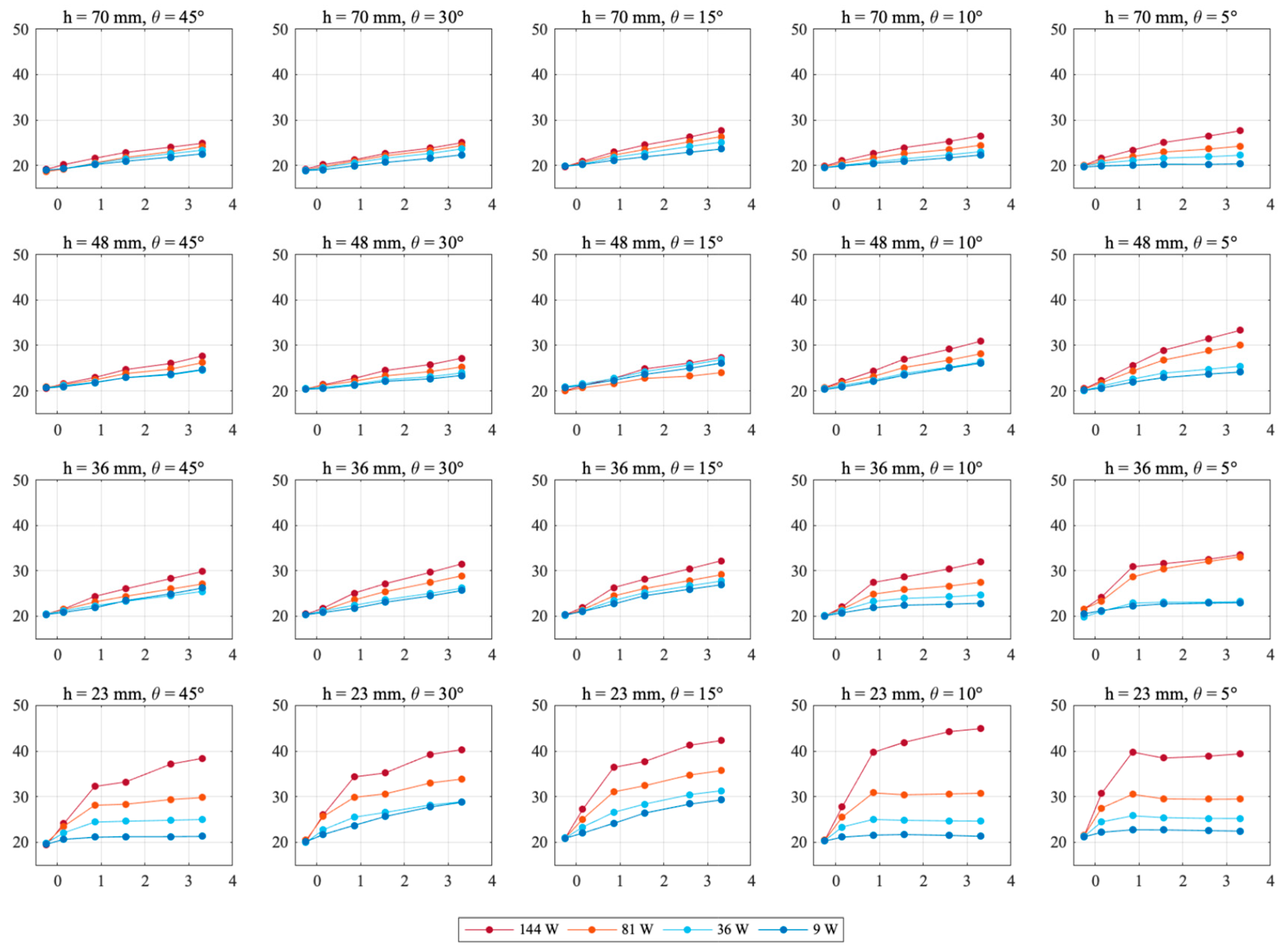
5.1.1. Temperature Profile along the Cavity

The temperature profiles along the air cavity from inlet to outlet demonstrated that air temperatures increased gradually dependent on the distance from the cavity inlet. This applied to all test variations, except the combination of h = 23 mm and θ = 5°. In this case, the temperatures showed a small drop in magnitude closer to the cavity outlet. This could possibly be caused by a reflux of air at the outlet. The general increase in air temperature detected along the air cavity is in line with corresponding experimental measurements [27,31,32,33,34].
The air temperature increase was not linear for all cases. Larger air cavities showed a more linear relationship between temperature increase and distance from the inlet, while smaller air cavities showed a rapid increase in temperature in the first half of the cavity. Beyond this, a gradual increase was observed. This could be due to different characteristic lengths, as presented in Section 2, given the different air cavity heights.

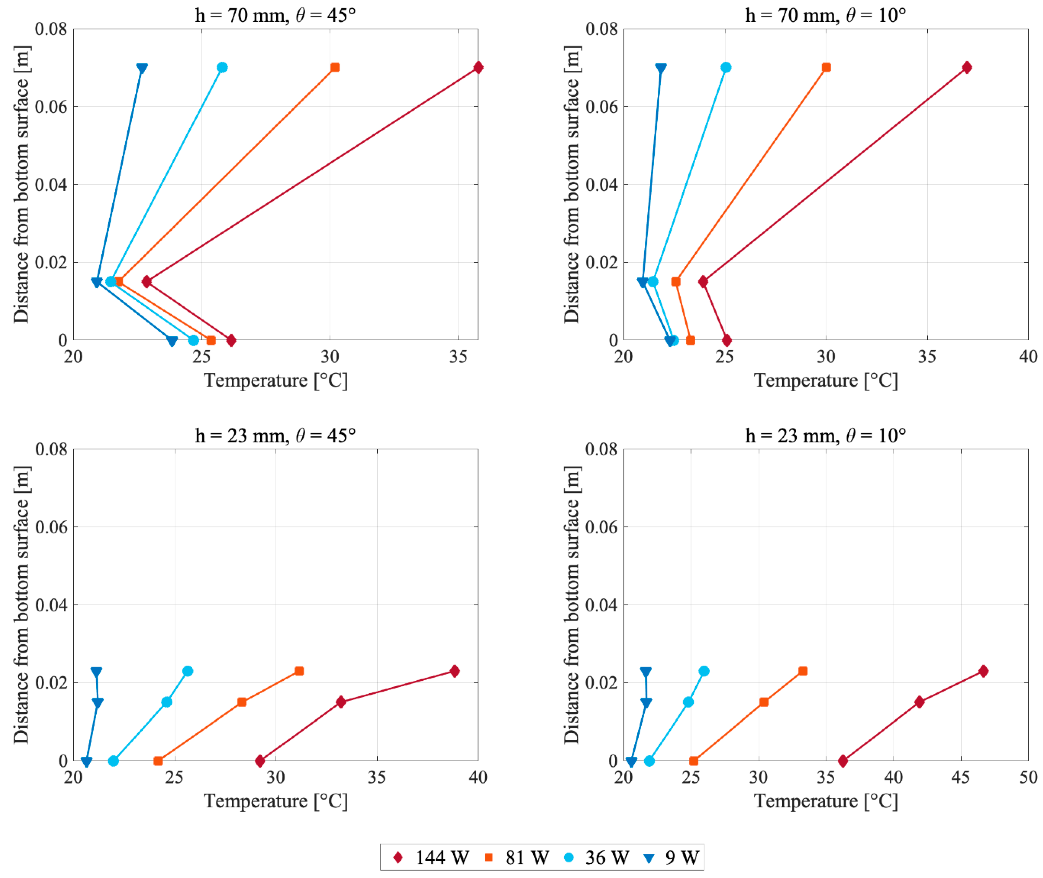
5.1.2. Temperature Profile across the Cavity

An examination of the temperature profiles across the air cavity height verified that the top surface temperature, i.e. the temperature on the heating foil, was the largest temperature in the cavity cross-section. The temperature of the bottom surface of the cavity was higher than the air temperature in most test variations. This is due to radiation from the heated top to the unheated bottom surface. Earlier research [32,33] has also observed that the cavity air temperature is lower than the temperature of the unheated cavity surface.
In the case of small cavity heights, the present study found that measured air temperatures in the cavity were higher than the temperatures on the unheated surface, due to a smaller airflow cooling the thermocouples. In addition, the thermocouples were fixed at the same height in the cavity during all test setups. Consequently, the distance between the thermocouples measuring air temperature and the heated surface was smaller for smaller air cavity heights.
The temperature distribution on the unheated surface in the cavity is important for the resulting temperature profiles of the cavity air. There are some uncertainties related to the temperatures of this surface as the time constant of the surface material is larger than that of the air and the heated surface. As most attention was given to stabilizing the temperature on the heating foil between test setups, it was observed that the bottom surface temperature in some cases was larger than desired due to thermal inertia.

5.1.3. Influence of Air Cavity Design and Heat Power Level

The results presented in Figure 5 and Figure 6 demonstrate that air temperatures in the cavity were dependent on both cavity height and inclination. The measurements imply that larger cavity height gives lower air temperature. As cavity height decreased, the air temperatures increased and approached the temperature on the heating foil. This is due to a smaller air volume being heated, and possibly a shorter characteristic length. As mentioned, the thermocouples were fixed at the same height above the unheated surface in the cavity during all test variations. Air temperature measured in the middle of the cavity for each cavity height might have shown different results. However, other research [27,32,34] has observed little difference in temperature between air in the middle of the air cavity and closer to the unheated surface.
Furthermore, Figure 5 shows increased air temperatures at decreased roof inclination. This is explained by less cooling due to a smaller airflow when the roof inclination decreases. In addition, higher applied heating power caused increased air temperatures. The measurements indicate that applied heating power has a larger influence when the air cavity is small, and the roof inclination is low.

5.1.4. Heat Power Level Related to Local Climate

The average temperature on the heating foil was found to vary between 21 °C and 43 °C, when including results at all heat power levels. For test setup h = 48 mm, θ = 45°, average top surface temperatures of 35 °C, 30 °C, 26 °C and 24 °C were measured at heat power levels 144 W, 81 W, 36 W and 9 W, respectively. A field study in Norway by Gullbrekken et al. [44], on a rectangular roof air cavity of h = 48 mm and θ = 40°, recorded average top surface temperatures in the cavity in the range −5 °C to 36 °C, 6 °C to 60 °C and 5 to 49 °C in periods in March, July and September, respectively. Comparing the two studies, the heat power levels utilized in the present study give cavity temperatures that would correspond to actual conditions in the middle of the day in spring, or in the morning/afternoon in summer in a Norwegian climate.

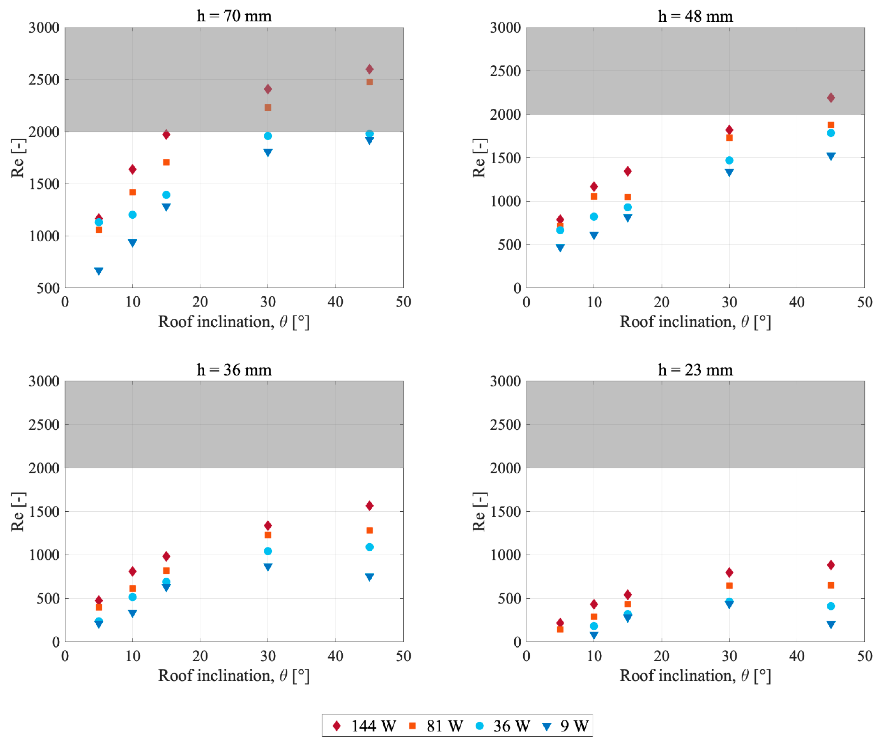
5.2. Air Velocity and Flow Conditions

5.2.1. Flow Characteristics

The calculated Reynolds number (Figure 9) shows that most studied airflows were laminar. Some measurements indicate possible transitional flow. However, no drastic change in flow conditions was observed as the assumed critical Reynolds number was approached. This means the critical Reynolds number may be larger than assumed. In determination of the average air velocity, uavg, the approximation uavg ≈ 0.67⋅umax was used. This is valid for wide rectangular ducts [41]. Given a more quadratic cavity, the factor multiplied with umax will be smaller, and found in the interval between 0.5 and 0.67. Consequently, the Reynolds number may be overestimated.

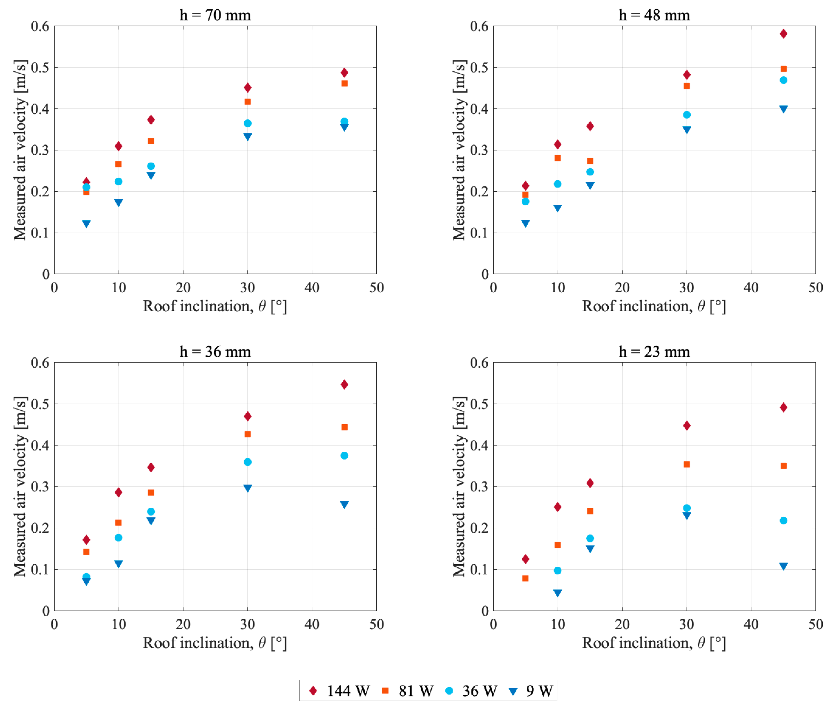
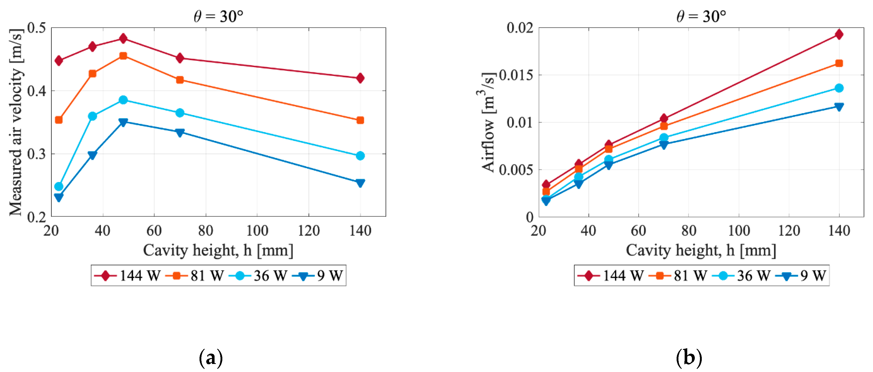
5.2.2. Influence of Air Cavity Design and Heat Power Level
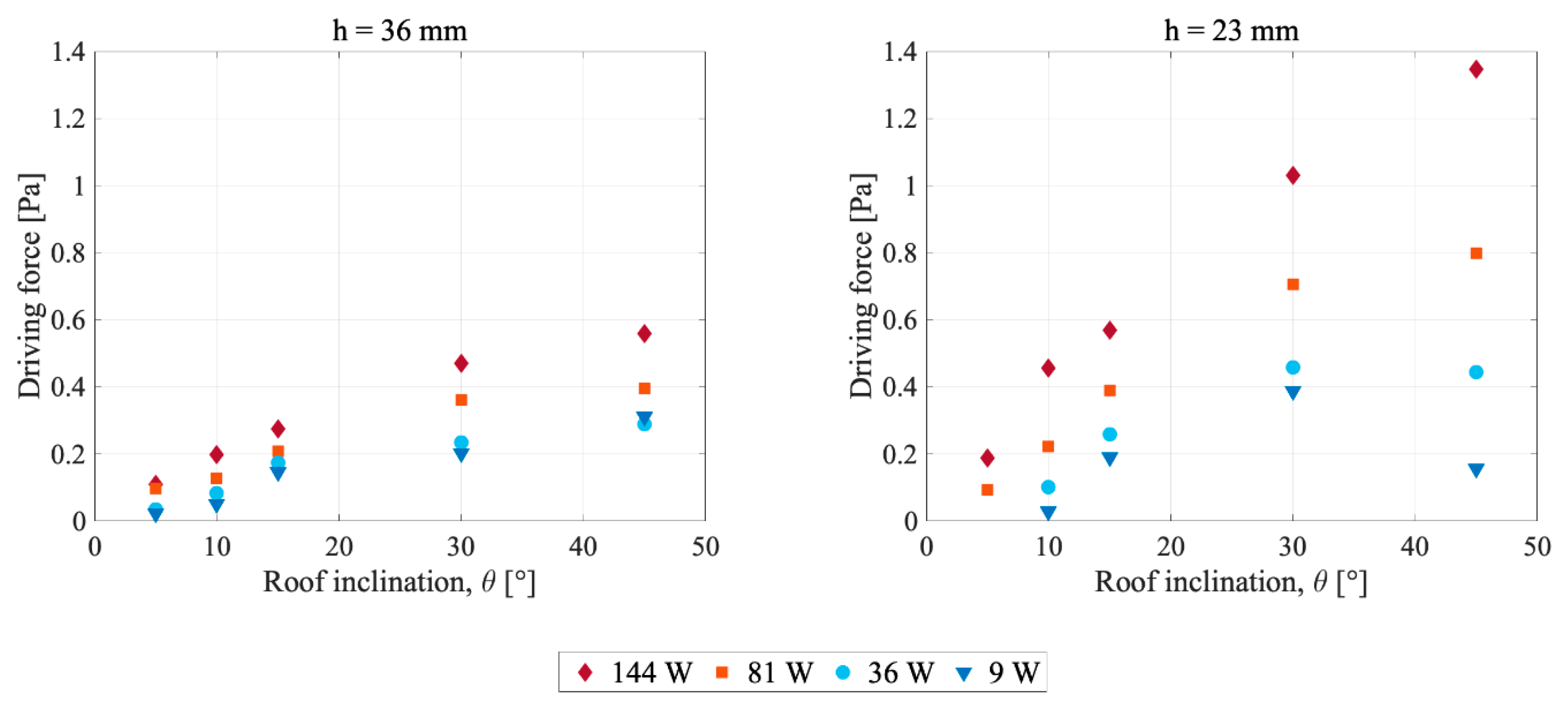
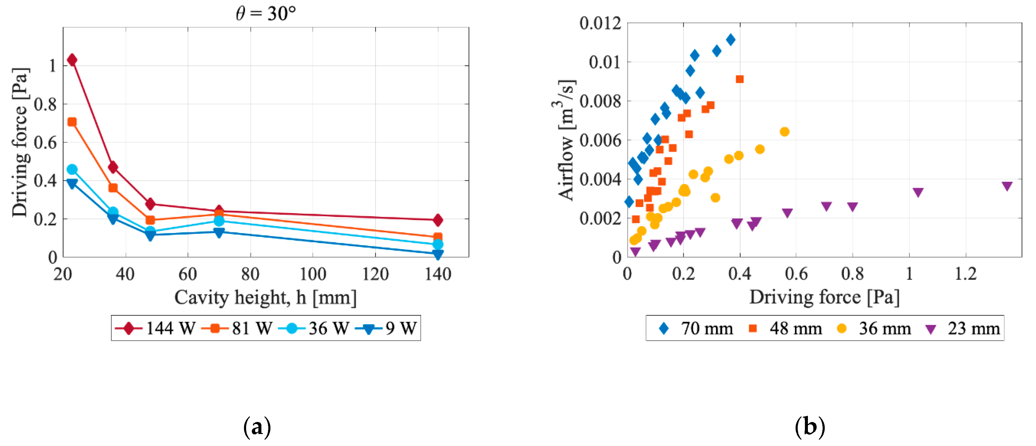
According to Figure 7, the measured air velocity generally increased with increased inclination. The same trend was observed for calculated airflow. Therefore, a larger roof inclination is recommended in order to maximize air velocity and airflow rate. It was observed that h = 23 mm and h = 36 mm combined with low heat power levels gave decreased velocity when the inclination was increased from 30° to 45°. For h = 23 mm, this may be explained by a drop in the driving force, as presented in Figure 10. The reason for decreased velocity when h = 36 mm is not known.
In general, the results showed an increase in measured air velocity and airflow with increased cavity height. However, in the case of roof inclinations of 30° and 45°, it was observed that the measured air velocity decreased when the cavity height was increased beyond 48 mm, as shown in Figure 7 and Figure 8a. At inclinations of 5 to 15°, the velocity was stable or increased slightly for the same increase in cavity height. The results therefore imply that an upper boundary for the air velocity through the cavity exists. Both Bunnag et al. [33] and Zhai et al. [34] concluded that air velocity in an air cavity decreased with increased cavity height. However, the studies only investigated air cavities with height larger than 100 mm and 140 mm, respectively. Sandberg and Moshfegh [31] observed the same trend when increasing the cavity height from 60 mm to 115 mm and further. This supports the hypothesis of the existence of an upper limit for the air velocity.
In most test runs, larger heat power was associated with a higher temperature rise, and therefore higher air velocity. In practice, this indicates that large air changes in the cavity coincide with strong solar radiation on the roof. This is beneficial for cooling and efficiency of ventilated BIPV on roofs. It is also favorable for drying of roofs.

5.3. Driving Force

Calculated thermal driving force showed dependence on cavity height, roof inclination and heat power level, as given in Figure 10. Smaller air cavity height gave larger driving force due to larger temperature differences. The relationship between driving force and roof inclination is observed to be close to linear. This implies that the height difference between the inlet and outlet is of great importance in determining the driving force. Figure 11a underlines how the thermal driving force decreased when cavity height was increased. The air temperature measurements given in Figure 5 were used as a basis for calculation of the thermal driving force. Consequently, constant temperature in the cavity cross-section was assumed, which may have over or underestimated the driving force for small or large cavities, respectively.
The thermal driving force is dependent on temperature differences and height differences, which are shown (Figure 10) to be related to the air cavity height and roof inclination, respectively. In order to maximize the thermal driving force, the roof inclination should be increased, and the cavity height reduced. In some cases, the driving force was observed to increase when inclination decreased. This is explained by high bottom surface temperatures due to thermal inertia in the roof construction, elevating the air temperature and hence the driving force at some inclinations.
At a given air cavity height, Figure 11b demonstrates that larger driving force is associated with larger airflow, as stated by Equation (1). The figure also shows that reducing the air cavity height led to a reduced airflow. Hence, airflow decreased when cavity height decreased, even though driving force increased. This implies increased flow resistances when air cavity height is decreased. Consequently, if maximization of airflow rate in the cavity is desired, a small air cavity is unfavorable.

6. Conclusions

In the present study, experimental investigations of thermal buoyancy in the air cavity of pitched ventilated roofs were performed to answer the following research questions: (1) How are the temperature conditions in the air cavity related to the air cavity design? (2) How is the airflow through the cavity influenced by the air cavity design? (3) To what degree may thermal buoyancy drive airflow in the air cavity? The temperature (1) and flow conditions (2) in the cavity were observed to be dependent on both cavity height and roof inclination. Increased inclination and air cavity height gave decreased air temperatures. Increased inclination gave increased velocities and airflows, while increased air cavity height only increased the air velocity until a certain point. The latter implies a possible optimal air cavity height of 48 mm for maximizing air velocity in the cavity. Theoretically, increased roof inclination and increased temperature difference between the air cavity and the ambient air will increase the driving force caused by thermal buoyancy. This was verified in the study. Hence, to maximize the thermal driving force (3) in the cavity of ventilated roofs, the roof inclination should be increased and the air cavity height should be decreased. By increasing the air cavity height from 23 to 70 mm, the driving force was reduced by two thirds. Increasing the roof inclination was of larger importance in the case of small air cavity height. However, if maximizing the airflow rate in the cavity is desired, the study observed that cavity height should be increased.
In order to fully address the challenges of roof ventilation given the Nordic context, buoyancy forces due to cooling of the cavity air, e.g., due to snow on the roof or longwave radiation, should be investigated. In addition, further research should study thermal buoyancy in combination with driving forces from wind pressure, complemented by moisture simulations to predict the risk of condensation and moisture damage in ventilated pitched wooden roofs.

Author Contributions

Conceptualization, T.K., L.G. and P.W.; methodology, N.S.B., T.S., M.S. and J.L.; validation, T.K., L.G. and P.W.; formal analysis, N.S.B., T.S. and M.S.; investigation, N.S.B., T.S. and M.S.; resources, T.K. and L.G.; writing—original draft preparation, N.S.B.; writing—review and editing, T.S., M.S., T.K., L.G., P.W. and J.L.; visualization, N.S.B.; supervision, T.K., P.W. and J.L. All authors have read and agreed to the published version of the manuscript.

Funding

This research was funded by the Research Council of Norway, grant number 237859. The authors gratefully acknowledge the financial support by the Research Council of Norway and several partners through the Centre of Research-based Innovation “Klima 2050” (www.klima2050.no).

Conflicts of Interest

The authors declare no conflict of interest.

Appendix A

Figure A1. Temperatures (°C) (y-axis), in the cavity air as a function of distance (m) from the cavity inlet (x-axis). Each plot represents a given air cavity height (h) and roof inclination (θ).
Buildings 10 00008 g0a1
Figure A2. Temperatures (°C) (x-axis), as function of distance from the bottom unheated surface (m) (y-axis). Each plot represents a given air cavity height (h) and roof inclination (θ).
Buildings 10 00008 g0a2

References

  1. Edvardsen, K.; Ramstad, T. Trehus Håndbok 5 [Wooden Houses. Handbook 5]; SINTEF Building and Infrastructure: Oslo, Norway, 2014. [Google Scholar]
  2. Gullbrekken, L.; Kvande, T.; Jelle, B.P.; Time, B. Norwegian pitched roof defects. Buildings 2016, 6, 24. [Google Scholar] [CrossRef] [Green Version]
  3. Blom, P. Venting of attics and pitched, insulated roofs. J. Therm. Envel. Build. Sci. 2001, 25, 32–50. [Google Scholar] [CrossRef]
  4. Blom, P. Ventilasjon av isolerte, skrå tretak [Venting of Insulated, Pitched Roofs]. Ph.D. Thesis, Norwegian Technical University, Trondheim, Norway, 1990. [Google Scholar]
  5. Norton, B.; Eames, P.C.; Mallick, T.K.; Huang, M.J.; McCormack, S.J.; Mondol, J.D.; Yohanis, Y.G. Enhancing the performance of building integrated photovoltaics. Sol. Energy 2011, 85, 1629–1664. [Google Scholar] [CrossRef] [Green Version]
  6. Shukla, A.K.; Sudhakar, K.; Baredar, P. A comprehensive review on design of building integrated photovoltaic system. Energy Build. 2016, 128, 99–110. [Google Scholar] [CrossRef]
  7. Zhang, T.; Tan, Y.; Yang, H.; Zhang, X. The application of air layers in building envelopes: A review. Appl. Energy 2016, 165, 707–734. [Google Scholar] [CrossRef]
  8. Roels, S.; Langmans, J. Highly insulated pitched roofs resilient to air flow patterns: Guidelines based on a literature review. Energy Build. 2016, 120, 10–18. [Google Scholar] [CrossRef]
  9. Bøhlerengen, T. Isolerte skrå tretak med lufting mellom vindsperre og undertak [Insulated pitched wooden roofs ventilated between the underlayer roof and the wind barrier]. In SINTEF Building Research Design Guides 525.101; SINTEF: Oslo, Norway, 2007. [Google Scholar]
  10. Bøhlerengen, T. Isolerte skrå tretak med kombinert undertak og vindsperre [Insulated pitched wooden roofs with combined underlayer roof and wind barrier]. In SINTEF Building Research Design Guides 525.102; SINTEF: Oslo, Norway, 2012. [Google Scholar]
  11. Gullbrekken, L.; Uvsløkk, S.; Kvande, T.; Petterson, K.; Time, B. Wind pressure coefficients for roof ventilation purposes. J. Wind Eng. Ind. Aerodyn. 2018, 175, 144–152. [Google Scholar] [CrossRef]
  12. Walker, T.S.; Forest, T.W. Field measurements of ventilation rates in attics. Build. Environ. 1995, 30, 333–347. [Google Scholar] [CrossRef]
  13. Falk, J.; Sandin, K. Ventilated rainscreen cladding: Measurements of cavity air velocities, estimation of air change rates and evaluation of driving forces. Build. Environ. 2013, 59, 164–176. [Google Scholar] [CrossRef]
  14. Ciampi, M.; Leccese, F.; Tuoni, G. Energy analysis of ventilated and microventilated roofs. Sol. Energy 2005, 79, 183–192. [Google Scholar] [CrossRef]
  15. Villi, G.; Pasut, W.; De Carli, M. CFD modelling and thermal performance analysis of a wooden ventilated roof structure. Build. Simul. 2009, 2, 215–228. [Google Scholar] [CrossRef]
  16. Susanti, L.; Homma, H.; Matsumoto, H.; Suzuki, Y.; Shimizu, M. Numerical simulation of natural ventilation of a factory roof cavity. Energy Build. 2010, 42, 1337–1343. [Google Scholar] [CrossRef]
  17. Susanti, L.; Homma, H.; Matsumoto, H. A naturally ventilated cavity roof as potential benefits for improving thermal environment and cooling load of a factory building. Energy Build. 2011, 43, 211–218. [Google Scholar] [CrossRef]
  18. Gagliano, A.; Patania, F.; Nocera, F.; Ferlito, A.; Galesi, A. Thermal performance of ventilated roofs during summer period. Energy Build. 2012, 49, 611–618. [Google Scholar] [CrossRef]
  19. Li, D.; Zheng, Y.; Liu, C.; Qi, H.; Liu, X. Numerical analysis on thermal performance of naturally ventilated roofs with different influencing parameters. Sustain. Cities Soc. 2016, 22, 86–93. [Google Scholar] [CrossRef]
  20. Bianco, V.; Diana, A.; Manca, O.; Nardini, S. Thermal behavior evaluation of ventilated roof under summer and winter conditions. Int. J. Heat Technol. 2017, 35, 353–360. [Google Scholar] [CrossRef]
  21. Bortolini, M.; Bottarelli, M.; Piva, S. Summer thermal performance of ventilated roofs with tiled coverings. J. Phys. Conf. Ser. 2017, 796, 012023. [Google Scholar] [CrossRef]
  22. Bianco, V.; Diana, A.; Manca, O.; Nardini, S. Numerical investigation of an inclined rectangular cavity for ventilated roofs applications. Therm. Sci. Eng. Prog. 2018, 6, 426–435. [Google Scholar] [CrossRef]
  23. De With, G.; Cherry, N.; Haig, J. Thermal benefits of tiled roofs with above-sheathing ventilation. J. Build. Phys. 2008, 33, 171–194. [Google Scholar] [CrossRef]
  24. Tong, S.; Li, H. An efficient model development and experimental study for the heat transfer in naturally ventilated inclined roofs. Build. Environ. 2014, 81, 296–308. [Google Scholar] [CrossRef]
  25. Biwole, P.H.; Woloszyn, M.; Pompeo, C. Heat transfers in a double-skin roof ventilated by natural convection in summer time. Energy Build. 2008, 40, 1487–1497. [Google Scholar] [CrossRef] [Green Version]
  26. Hofseth, V. Studie av luftede trekonstruksjoner [Study of Ventilated Roof Constructions]. Master’s Thesis, Norwegian University og Science and Technology, Trondheim, Norway, 2004. [Google Scholar]
  27. Susanti, L.; Homma, H.; Matsumoto, H.; Suzuki, Y.; Shimizu, M. A laboratory experiment on natural ventilation through a roof cavity for reduction of solar heat gain. Energy Build. 2008, 40, 2196–2206. [Google Scholar] [CrossRef]
  28. Lee, S.; Park, S.H.; Yeo, M.S.; Kim, K.W. An experimental study on airflow in the cavity of a ventilated roof. Build. Environ. 2008, 44, 1431–1439. [Google Scholar] [CrossRef]
  29. Chami, N.; Zoughaib, A. Modeling natural convection in a pitched thermosyphon system in building roofs and experimental validation using particle image velocimetry. Energy Build. 2010, 42, 1267–1274. [Google Scholar] [CrossRef]
  30. Nusser, B.; Teibinger, M. Experimental investigations about the air flow in the ventilation layer of low pitched roofs. In Proceedings of the 2nd Central European Symposium on Building Physics, Vienna, Austria, 9–11 September 2013. [Google Scholar]
  31. Sandberg, M.; Moshfegh, B. Ventilated-solar roof air flow and heat transfer investigation. Renew. Energy 1998, 15, 287–292. [Google Scholar] [CrossRef]
  32. Khedari, J.; Yimsamerjit, P.; Hirunlabh, J. Experimental investigation of free convection in roof solar collector. Build. Environ. 2002, 37, 455–459. [Google Scholar] [CrossRef]
  33. Bunnag, T.; Khedari, J.; Hirunlabh, J.; Zeghmati, B. Experimental investigation of free convection in an open-ended inclined rectangular channel heated from the top. Int. J. Ambient Energy 2004, 25, 151–162. [Google Scholar] [CrossRef]
  34. Zhai, X.Q.; Dai, Y.J.; Wang, R.Z. Experimental investigation on air heating and natural ventilation of a solar air collector. Energy Build. 2005, 37, 373–381. [Google Scholar] [CrossRef]
  35. Sandberg, M.; Moshfegh, B. The investigation of fluid flow and heat transfer in a vertical channel heated from one side by PV elements. Part II. Experimental study. Renew. Energy 1996, 8, 254–258. [Google Scholar] [CrossRef]
  36. Gullbrekken, L.; Uvsløkk, S.; Geving, S.; Kvande, T. Local loss coefficients inside air cavity of ventilated pitched roofs. J. Build. Phys. 2017, 42, 197–219. [Google Scholar] [CrossRef] [Green Version]
  37. Hagentoft, C.-E. Introduction to Building Physics; Studentlitteratur AB: Lund, Sweden, 2001. [Google Scholar]
  38. Kronvall, J. Air Flows in Building Components. Ph.D. Thesis, Lund University, Lund, Sweden, 1980. [Google Scholar]
  39. Geving, S.; Thue, J.V. Fukt i Bygninger [Moisture in Buildings]; Norges Byggforskningsinstitutt: Oslo, Norway, 2002. [Google Scholar]
  40. Cengel, Y.A.; Cimbala, J.M. Fluid Mechanics, Fundamentals and Applications, 3rd ed.; McGraw Hill Education: Boston, MA, USA, 2014. [Google Scholar]
  41. ASHRAE. 2005 ASHRAE Handbook: Fundamentals; American Society of Heating, Refrigerating and Air-Conditioning Engineers: Atlanta, GA, USA, 2005. [Google Scholar]
  42. Hansen, H.E.; Kjerulf-Jensen, P.; Stampe, O.B. Varme-og Klimateknik, Grundbog, 4th ed.; Danvak ApS: København, Denmark, 2013. [Google Scholar]
  43. Arfvidsson, J.; Harderup, L.-E.; Samuelson, I. Fukthandbok: Praktik och teori [Moisture Handbook: Practice and Theory], 4th ed.; AB Svensk Byggtjänst: Stockholm, Sweden, 2017. [Google Scholar]
  44. Gullbrekken, L.; Kvande, T.; Time, B. Ventilated wooden roofs: Influence of local weather conditions-measurements. In Proceedings of the 11th Nordic Symposium on Building Physics, Trondheim, Norway, 11–14 June 2017; pp. 777–782. [Google Scholar]
Figure 1. (a) Top aluminium lid showing the arrangement of XPS and heating foil on the inside of the air cavity; (b) complete test model, at 0° inclination; (c) inclined model with plastic foil cover, at 45° inclination.
Buildings 10 00008 g001
Figure 2. Position of the thermocouples in the air cavity (T = top, A = air, B = bottom, h = height of the air cavity, H = height difference between the cavity inlet and outlet). Lengths between measuring points are given in millimetres.
Buildings 10 00008 g002
Figure 3. (a) Validation of the experimental method, presented as a comparison of measured air velocity in initial test run and a control test run for test setup h = 48 mm, θ = 15°; (b) Comparison of methods utilized for smoke production, at test setup h = 48 mm, θ = 15°. The mean is calculated as the average of the five measurements.
Buildings 10 00008 g003
Figure 4. Analysis of thermocouple position on the heating foil at different levels of heating power. Placement completely on, partially on, and between the electrically conducting heating elements was tested in the middle of the cavity. Placement on the edges of the heating foil width was also included.
Buildings 10 00008 g004
Figure 5. Temperatures (°C) in the cavity air as a function of distance (m) from the cavity inlet. Each plot represents a given air cavity height (h) and roof inclination (θ).
Buildings 10 00008 g005
Figure 6. Temperatures (°C) as a function of distance from the bottom unheated surface (m). Each plot represents a given air cavity height (h) and roof inclination (θ).
Buildings 10 00008 g006
Figure 7. Measured air velocities at different roof inclinations, air cavity heights and applied heating power. Note that measured air velocity is the assumed maximum velocity through the air cavity.
Buildings 10 00008 g007
Figure 8. (a) Measured air velocity in relation to the air cavity height at a roof inclination of 30°; (b) Calculated airflow rate presented in relation to the air cavity height at a roof inclination of 30°.
Buildings 10 00008 g008
Figure 9. Reynolds number, Re, as a function of roof inclination. The shaded area represents possible beginning of the transitional flow region.
Buildings 10 00008 g009
Figure 10. Thermal driving force at different roof inclinations, air cavity heights and applied heating power.
Buildings 10 00008 g010aBuildings 10 00008 g010b
Figure 11. (a) Driving force as a function of cavity height at a roof inclination of 30°; (b) airflow rate and driving force for different air cavity heights. Measurements at all roof inclinations are included in the diagram.
Buildings 10 00008 g011

