Article

Mechanical Properties of Ultra-High Performance Concrete with Partial Utilization of Waste Foundry Sand

Department of Structural Engineering, Faculty of Civil Engineering and Architecture, Lublin University of Technology, 20-618 Lublin, Poland
Buildings 2020, 10(1), 11; https://doi.org/10.3390/buildings10010011
Submission received: 23 December 2019 / Accepted: 10 January 2020 / Published: 14 January 2020

Abstract

:
Waste foundry sand (WFS) is a ferrous and non-ferrous foundry industry by-product, produced in the amount of approximately 700 thousand tons annually in Poland and it is estimated that only a small percentage of this waste is recycled. The study used WFS to produce ultra-high performance concrete (UHPC) as a partial substitute for quartz sand. It was replaced with WFS levels of 0%, 5%, 10%, and 15% by weight of quartz sand content. The UHPC mixtures were produced and tested to determine the compressive strength, flexural strength, splitting tensile strength as well as the modulus of elasticity at 28, 56, and 112 days. Scanning electron microscope (SEM) analysis was done to identify the presence of various compounds and micro-cracks in UHPC with WFS. The results revealed an increase as well as an insignificant decrease in the mechanical properties up to 5% and 10% WFS replacement, respectively. These studies also prove improvement in the microstructure of UHPC up to a 5% WFS level. In all the tested properties in this work, 5% WFS was found to be an apt substitute for quartz sand.

1. Introduction

Nowadays, practices related to the development of sustainable construction have the highest priority. Of all the world’s building materials, concrete is the most widely used, therefore it is obvious that sustainable concrete is also increasingly gaining more supporters primarily due to its ability to accommodate recycled materials and its greater durability than conventional concrete.
Waste foundry sand (WFS) is a ferrous and non-ferrous foundry industry by-product. Foundry sand is a silica sand that is reused a number of times to fabricate new moulds, which after several repeated cycles accumulates an excessive level of impurities that could compromise their quality. For this reason, the mixture becomes useless in the fabrication of moulds and generates waste foundry sand (WFS). In the United States, Brazil, India, Spain and Poland, foundries generate about 8, 3, 1.7, 1, and 0.7 million metric tons of WFS per year, respectively, which is almost entirely disposed of in controlled landfills [1,2,3,4,5]. The recent average global recycling of this by-product is annually only a few percent. Landfilling WFS is not environmentally friendly, hence reusing the material would help to promote more sustainable waste disposal methods.
In general, there are two kinds of foundry sands based on different binding systems employed to form moulds for casting metals: green sands based on clay bonding and chemically bonded foundry sands. Both types of these sands after losing their usefulness in moulds production are still promising materials that can potentially be utilized as a substitute for fine aggregates or cement in the production of concrete. The waste mass of the moulding together with core is around 90% contaminated quartz sand, which after alloy casting may contain heavy metals. The remaining part is organic and inorganic chemical compounds in addition to dusty fractions [6]. In many modern foundries, moulding sands are reused for many production cycles. The use of bentonite mass as the basic substrate to produce moulds makes it possible to subject the pressed waste to refreshing processes and its re-processing. Recovery in the processes of regenerating a pure sand matrix for the purpose of its reuse as a replacement for fresh sand in newly prepared moulds is a complex issue due to technological and ecological aspects. Pre-regeneration is most often used for treating moulding sands. It enables improvement of their technological properties as a result of grinding lumps, removing impurities and cleaning the used binder from the grain surface of the mass by partial abrasion and its dedusting. It covers the fragmentation of broken moulds and cores to the size of single grains as a result of crushing, sieving, and granulometric classification [7]. The finest sand fractions cannot be reused and constitute waste mass directed to landfills, the main component of WFS. Studies have shown that is possible to utilize WFS in high-strength, normal and low-strength concrete and WFS can positively impact their mechanical properties [2,3,4,8,9,10,11,12,13,14,15,16].
The new generation concrete, ultra-high performance concrete (UHPC), has high compressive strength exceeding 120 N/mm2 [17,18,19], or according to other references 150 N/mm2 [20,21,22]. Ultra-high performance concrete (UHPC) is considered a very durable material due to its very high strength-to-weight ratio compared to conventional concrete [18]. Nevertheless, on the other hand, it is very sensitive to explosive spalling in fire conditions resulting from its low permeability and dense structure [22,23]. UHPC is usually produced using a high cement content, very fine sand with a grain size below 0.6 mm, water, silica fume, superplasticizers based on polycarboxylate ethers and steel fibres [18]. In order to increase the mix homogeneity, coarse aggregate is usually completely excluded, while the water-to-binder material ratio is less than 0.2. The material is currently used in the construction of footbridges, highway bridges, as well as precast lattice systems for stadiums and tall buildings [21,24]. The use of coarse aggregates in UHPC is not common, but possible if the element size is much larger than the aggregate grain [25]. Coarse aggregates up to 8 or 16 mm were used to produce UHPC to reduce the cement content and the material price [26]. It is necessary for the coarse aggregates to have high strength (e.g., basalt, granite, calcined bauxite) to prevent UHPC from cracking due to the aggregate grains [27]. Numerous investigations are conducted to produce good UHPC with commercially available materials. Yang et al. showed that UHPC produced with coarse limestone aggregate can achieve high permeability, low shrinkage and a flexural strength of 10 MPa [28]. Wang et al. [29] reported that UHPC can be produced without removing the coarse aggregate by curing at room temperature. Their UHPC had a low w/cm ratio, a high content of cement materials, steel fibers, limestone powder, as well as a combined efficient superplasticizer and retarder. Camacho et al. [25] investigated UHPC suitable to produce precast elements by using locally available materials (including limestone coarse aggregate) with standard mixing and curing processes. Although there are small differences between the strengths and deformations of the cementitious matrix and the aggregates, straight-lined cracks propagate through all the components of coarse-grained UHPC. Torres et al. [30] reported the possibility of utilizing WFS in UHPC as 10%, 20% and 30% replacement of river sand by evaluating the compressive strength, splitting tensile strength, flexural strength, elastic modulus and Poisson’s ratio of UHPC. In their studies, cement, silica fume, fine aggregates (river sand and WFS) with a grain size below 0.595 mm, superplasticizer and water was used to produce UHPC. They concluded that all the strengths increased with 10% WFS replacement and decreased with 30% WFS substitution. In addition, no statistically significant change of UHPC properties were observed with 20% WFS.
Numerous studies have been published on utilizing WFS in conventional concretes. Only a few studies have been published regarding the use of WFS in high performance concrete and UHPC. An exhaustive literature review has shown that currently no published research exists on using WFS for fine aggregate in coarse-grained ultra-high performance concrete. UHPC is manufactured using large amounts of natural sand, which can easily be substituted with WFS owing to the fact that their sizes and fractions are alike. Hence, it is possible to recycle WFS in the production of a durable UHPC compound to demonstrate the impact of the waste on the properties of the concrete.
This research article discusses the results of experiments conducted to evaluate the fresh properties of coarse-grained UHPC (slump, density), its physical properties (apparent density, open porosity, absorbability), mechanical properties (compressive strength, flexural strength, splitting tensile strength and modulus of elasticity), as well as microstructural analysis after replacing 0%, 5%, 10%, and 15% natural fine aggregate by WFS.

2. Materials and Methods

2.1. Cementing Materials

CEM I 52.5N-HSR/NA Portland cement (CEMEX, Chełm, Poland) was used, which satisfies PN-EN 197-1:2012 [31] and PN-B-19707:2013 [32]. This cement was selected as it is locally available and can be employed to produce ultra-high performance concrete, intended for use in chemically aggressive environments such as bridges, roads, airport structures, hydrotechnical, industrial and ecological constructions, as well as to produce precast concrete in communication engineering. Silica fume was used to compact the concrete matrix in the interfacial transition zone (ITZ) of the aggregate grains with the cement paste. The average particle size of the silica fume particles of approximately 0.1 μm enables accurate filling of free spaces, in consequence, the strength and durability of the hardened concrete is improved. The specific surface area of silica fume is 17,000 m2/kg. Table 1 presents the cement’s physical properties, while Table 2 gives the chemical compositions of the cement and silica fume.

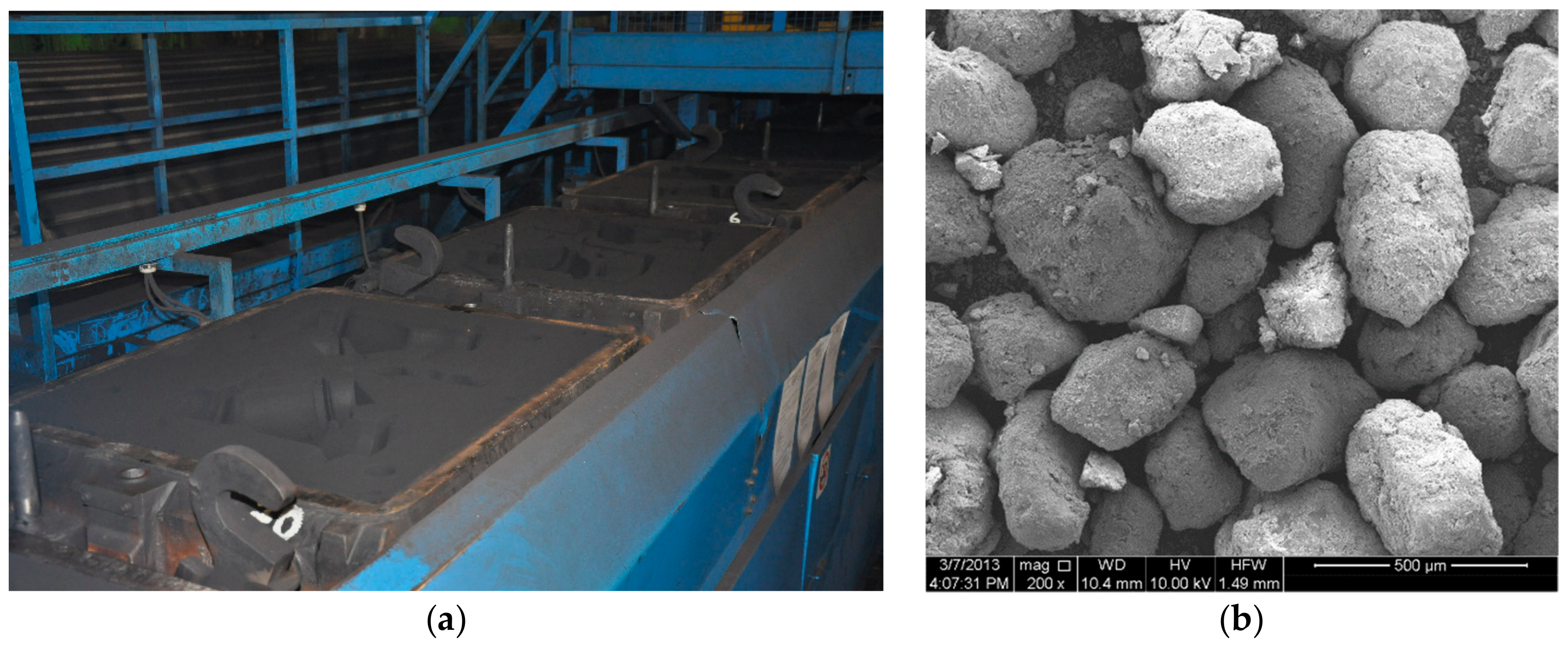
2.2. Natural Aggregates and Waste Foundry Sand

The coarse aggregate was 2/16 mm crushed basalt stone. Locally obtained quartz sand having a grain size of 0.125/2 mm was used for the natural fine aggregate in the UHPC mixtures.
WFS came from a local iron casting firm. It was waste sand from moulds employed in the foundry, see Figure 1a. It is classified as a clay bonded foundry sand commonly called green sand. The WFS was sieved to acquire a material finer than 2 mm to use as quartz sand replacement in UHPC. Figure 1b presents the microstructure of the WFS. The round to sub-angular shape of the WFS particles can be observed in the SEM micrograph.
Table 3 displays the physical properties of the aggregates and WFS, whereas Table 4 presents the chemical composition of the basalt, sand, and WFS determined by X-ray fluorescence (XRF).
By means of the chemical analysis, it was found that WFS contains a high level of SiO2, which is beneficial with reference to the mechanical strength of UHPC. Moreover, the two fineness modulus of both sands is much the same. It was also reported in paper [2] that a denser concrete was received, and in turn higher mechanical properties owing to the higher number of fine particles present in WFS. Beside having a high silica content, the WFS particles have a thin coating of dust, binder and burnt carbon (e.g., bentonite, resin, sea coal). In general, WFS contains less silica compared to quartz sand due to the additives present in WFS [10]. Table 5 gives the different reported chemical compositions of WFS [3,9,10,33,34] in comparison with the WFS in my study.
The chemical composition of WFS may vary depending on the type of metal, combustible used, as well as the type of binder. The composition further influences WFS performance. Moreover, the chemical and physical properties of WFS from various stages of foundry processing differ [35]. However, foundry sands produced from a single foundry or foundries consortia should not show significant variation over time and are often characterized by a consistently equivalent chemical composition.
The particle size distributions of basalt coarse aggregate, quartz sand and WFS were ascertained according to PN-EN 933-1:2012 [36]. By means of sieve analyses, it was found that the grain size distribution of the quartz sand and the WFS were rather similar. It can be concluded that WFS is a compatible substitute for quartz sand regarding grain size.

2.3. Mixture Proportions

The UHPC mixtures proportions were formulated on the basis of a literature review. In previous research, high contents of cement, fine natural sand and silica fume were mostly used to prepare UHPC [29,37]. It was found that the most successful fine aggregate replacements with WFS in conventional concrete were predominantly below 30% [2,8,11,14].
The UHPC mixture formulations in this study contained fine quartz sand passed through a sieve to receive a size of <2 mm and coarse basalt stone passed through a sieve <16 mm, type I Portland cement, and condensed silica fume based on previous studies [19,23]. The optimal amount of silica fume was selected based on experience [38]. The water-cementitious materials ratio (w/cm) of the mixtures was maintained at 0.24 so as to monitor the impact of WFS on the UHPC properties. The utilized WFS was passed through a sieve less than 2 mm to fit the grain sizes between the fine aggregates. The quartz sand was substituted with WFS in amounts of 0%, 5%, 10%, and 15% of the sand mass. A light yellow polycarboxylate ethers-based, liquid superplasticizer was added to the UHPC mixtures, equalling 3% of the mass of the cementitious materials, to achieve sufficient workability. The specific gravity of the material amounts to 1.07 at 20°C, contains alkali < 1.5% and chlorides < 0.1%, and does not give rise to air entrainment. The reference slump for the control mixture was 120 ± 20 mm. The unit weight test and slump test for workability were conducted on fresh UHPC. Table 6 presents all the UHPC mixture proportions and fresh properties.
When the WFS was added to the mixtures, decreases in the slump values and unit weights were observed with an increasing amount of WFS. Prabhu et al. [11] discovered that an augmentation in WFS content up to 10% reduced the slump of normal strength concrete, and then remained constant for dosages up to 50% WFS.

2.4. Preparation and Casting of UHPC Specimens

The basalt, quartz sand and WFS were oven dried for 24 h at 100 °C after they had been sieved. Following drying, mixing of the ingredients of each mixture was carried out for approximately 12 min with a 100 L laboratory mixer. For the first 4 min only the dry aggregates were mixed, next half of the water was poured in. The cement and silica fume were added afterwards. After thorough mixing (about 4 min), the superplasticizer with the remaining water were poured into the mixer. The mixing sequence used was based on earlier experience [39]. Following mixing, the slump test was performed to ascertain the workability of the mixtures. The slump values are listed along with the fresh concrete density in Table 6. Then the mixtures were placed in moulds, which were next put on a vibrating table shaking at a rate of 150 Hz. UHPC from the same batch was used to cast all the specimens for each WFS replacement percentage. The same mixing and compacting sequence was followed to produce each UHPC mixture. The same curing regime was used for all the UHPC specimens so as to limit as many variables as possible. Curing the specimens for the first 24 h at room temperature 20 ± 2 °C was the regime that was implemented. After demolding, curing of the specimens in a water bath at 20 ± 2 °C lasted to 2 days before testing at 28, 56 and 112 curing days. Dry curing of the specimens at 100 °C was carried out after they had been taken out of the water bath two days before testing. 48 specimens are still being kept for further testing of the mechanical properties of UHPC with WFS after 2 years of maturation. The specifications of the UHPC specimens are given in Table 7.
Small representative pieces from both the CWFS0 and CWFS5 batches after the tensile splitting test were taken to prepare three thin-layer polished plates of each of the selected UHPC specimens for SEM analysis. The pieces were soaked, rinsed, dried in an oven at 60 °C, then prior to testing they received a coating of gold powder. An accelerating voltage of 15 kV was used to carry out the SEM investigations.

3. Results and Discussion

3.1. Physical Properties

Tests of the apparent density, absorbability, and open porosity were carried out on a set of three 100 × 100 × 100 mm cubic specimens of each mixture in compliance with the PN-EN 12390-7:2011 [40] and PN-EN 13755:2008 [41] recommendations. The mean results and standard deviations of the UHPC physical properties are displayed in Table 8.
An increase in the WFS content from 5% to 15% affects a gradual increase in the apparent density of the UHPC up to 2%, and reduces both the absorbability and open porosity by 15%. It can be observed that the density of UHPC rises due to the free spaces being filled with finer grains of waste sand. Guney et al. were also able to reduce the absorbability of high strength concrete by increasing the waste sand content [9].

3.2. Compressive Strength

At 28, 56, and 112 days, in accordance with PN-EN 12390-3:2011 [42], the compressive strength of the UHPC mixtures containing WFS was ascertained. An average of three specimens were tested per data point. The impact of the WFS content on the development of the compressive strength can be seen in Figure 2. The lines at the top of the bars denote the standard deviation.
The designed compressive strength for the CWFS0 control mixture at 28 days was 120 ± 5 MPa. The CWFS0 mixture obtained an average compressive strength of 122.2 MPa, 129.8 MPa and 140.4 MPa at 28, 56 and 112 days, respectively. The results also revealed that when a 5% WFS substitution for quartz sand was put into the mixtures, the compressive strength rose. The 28 day CWFS5 cubes attained a mean compressive strength of 135.5 MPa, which was 10.9% higher than that of the 28-day CWFS0 cubes. All the CWFS5 specimens had 8.5% higher compressive strengths on average compared to the control specimens. When studying CWFS10, cubes made with a 10% WFS substitution for quartz sand, the results revealed a drop in the compressive strength in contrast to the reference CWFS0 mixture. A comparison of the 28-day compressive strengths shows a loss of 5%. The mean strength loss from the reference to the 10% WFS replacement was 7.2%. Considering the last set of data for the CWFS15 mixture with an addition of WFS up to a 15% replacement, it was found that the compressive strength falls. The 28-day mean compressive strength shows a drop of 13.7%. Between the reference mixture and the cubes with 15% WFS substitution, the average declined in compressive strength amounted to about 13.5%. The results indicate that WFS raises the compressive strength of UHPC up to a 5% level of substitution. The 10% and 15% WFS replacements adversely affected the compressive strength of UHPC. The compressive strength results obtained in this study are different to those published on normal- and low-strength concrete with WFS [2,8]. The decrease in compressive strength in UHPC begins earlier, as early as at a 10% WFS replacement level. This can be attributed to some WFS impurities affecting both the rheology and density of UHPC as the WFS substitution for quartz sand increases. In addition, these differences may have resulted from the various materials and mixtures utilized in compared studies. Moreover, concrete with a low water to cement ratio more visibly showed the adverse influence of the WFS addition [14]. As can be observed in Table 6, both the workability and fresh density dropped, as the WFS content was augmented; this fall could result in lower compressive strengths at high levels of WFS replacement. The combined loss in workability and fresh density lead to a rise in compressive strength at 5% WFS substitution, whereas there were slight decreases at 10% and 15% WFS substitution. The loss in fresh density and workability is probably due to the higher angularity degree of the WFS in contrast to the smooth profile of the quartz sand employed as the fine aggregate [2,8]. Moreover, the large specific surface area of fine bentonite and pulverized coal particles causes them to absorb water and reduce the workability of normal-strength concrete as the WFS replacement level increases [43]. On the other hand, Portland cement hydration in conventional concrete can be enhanced by adding fine bentonite and pulverized coal particles [16]. C-S-H gels can be formed on fine particles acting as nucleation points, as a result hydration reactions occur and in turn heat release [44]. This phenomenon may induce an increase in the mechanical strength of UHPC. Nevertheless, the water adsorption by the bentonite and coal particles affects a lower effective water/cementitious materials ratio with a percentage increase in WFS-containing mortars [45]. A similar phenomenon can decrease Portland cement hydration also in this study, and may lead to more significant shrinkage, which may bring about a reduction in the UHPC compressive strength with 10% and 15% WFS replacement.

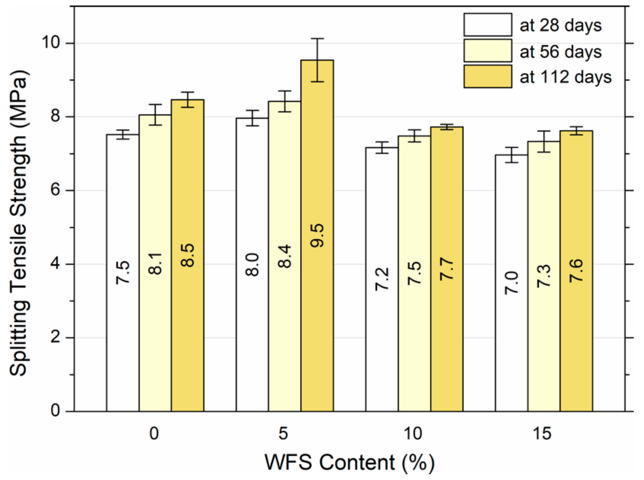
3.3. Splitting Tensile and Flexural Strength

Splitting tensile strength tests were carried out at 28, 56, and 112 days according to PN-EN 12390-6:2011 [46]. Figure 3 shows the differences in the splitting tensile strength of UHPC with the various WFS contents.
This variation with any amounts of WFS was quite alike to that seen as regards the compressive strength. A trend of a rise in splitting tensile strength with an increase in WFS up to 5% replacement followed by a decrease was noticed. The splitting tensile strength values for the reference mixture of 7.5 MPa, 8.1 MPa and 8.5 MPa at 28, 56 and 112 days, respectively were observed. As with the compressive strength, a slight rise of roughly 7.4% in the results for the 5% WFS mixture for all the three ages was noted. A decline in the splitting tensile strength of UHPC for the 10% and 15% WFS ensued. In particular, there was a mean decrease of about 7.5% for the UHPC from 0% to 10% WFS. Then there was a decrease of 10% from 0% to 15% WFS. Notwithstanding, there was no significance between the 0% and 15% WFS, which is an advantageous result as it reveals that WFS has no effect on the splitting tensile strength at 15% substitution; this can increase UHPC durability without compromising splitting tensile strength. Similar to the results of the compressive strength, the impact of WFS on reducing the density and workability of low-, normal- and high-strength concrete had much the same influence on the splitting tensile strength [3,4,8,9,10,11,12,13,14,15,16].
Flexural strength examinations were carried out at 28, 56, and 112 days in accordance with PN-EN 12390-5:2011 [47]. Figure 4 plots the flexural strength against the WFS replacement level.
The results displayed in Figure 4 illustrate that with age, the flexural strength rises. A stable increase of about 8.1% with age was found with respect to the specimens made from the reference mixture without WFS. The CWFS0 mixture reached a mean flexural strength of around 9.5 MPa, 10.3 MPa and 11.1 MPa at 28, 56 and 112 days respectively. Regarding the CWFS5 mixture, flexural strength values of about 11.1 MPa, 11.5 MPa and 12.5 MPa were obtained at 28, 56 and 112 days, respectively. It was noticed that the flexural strength rose by roughly 13.7% with 5% WFS substitution. A minimal decline in flexural strength for 10% WFS replacement was also observed. Notably the CWFS10 mixture attained flexural strength values of around 9.1 MPa, 10.1 MPa and 11.1 MPa at 28, 56 and 112 days, respectively. What is more, the mean flexural strength of the CWFS10 mixtures amounted to about 10.1 MPa, a marginal reduction in the mean flexural strength when contrasted with the average flexural strength of the reference mixture, which was approximately 10.3 MPa. This was a 2% drop in flexural strength in comparison to the reference mixture CWFS0. Finally, the 15% WFS mixture had a mean flexural strength value of about 9.5 MPa. This meant a decline in the mean flexural strength of about 8.4% compared to the reference mixture. The fact that the flexural strength of UHPC lessens for the various WFS substitutions indicates that a poorer UHPC mixture is received when the WFS content is higher. These results indicated a considerable rise in flexural strength when WFS is added up to 5%, next this strength declines at replacement levels of 10% and 15% WFS. Even though there was a fall in the flexural strength with 10% and 15% WFS replacement, the tests indicated that with an amount of WFS up to 15%, the flexural strength is reduced by less than 10%. The results finally reveal the influence on the UHPC flexural strength due to WFS replacement up to 15%, but a only slight effect up to 10%. Once more, my results can be supported by the results published by other researchers on low-, normal- and high-strength concrete [3,4,8,9,10,11,12,13,14,15,16], in which WFS has an effect on the density and workability that results in an impact on the flexural strength values.

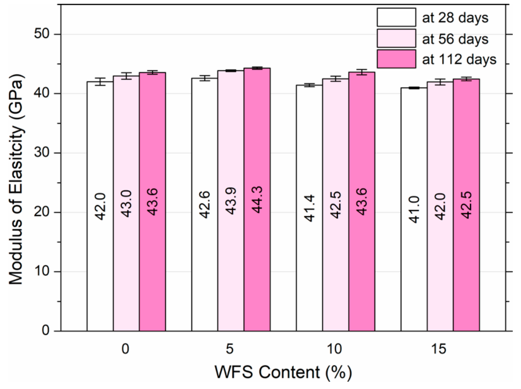
3.4. Modulus of Elasticity

In compliance with ASTM C469/C469M-14 [48], tests were conducted to determine the modulus of elasticity at 28, 56 and 112 days since it is an principle parameter in structural design. The elastic modulus was calculated at 40% of the maximum stress. Figure 5 displays the effect of the WFS content on modulus of elasticity development.
According to the results given in Figure 5, an increase was observed at 5% WFS replacement. Identical results to those of the reference UHPC were noted for the 10% WFS replacement at 112 days of curing. Small decreases were obtained by the 10% WFS replacement at 28 and 56 days of maturation, as well as the 15% WFS replacement at all the curing periods. Notably, the mean elastic modulus values for the reference mixture were 42 GPa, 43 GPa and 43.6 GPa at 28, 56 and 112 days, respectively. On the other hand, the 5% replacement exhibited the highest mean elastic modulus values of 42.6 GPa, 43.9 GPa, 44.3 GPa at each age tested. The specimens with the 10% WFS replacement showed mean results of 41.4 GPa, 42.5 GPa, 43.6 GPa, at 28, 56, and 112 days, respectively, which are similar to the reference samples. Finally, the 15% WFS replacement showed mean elastic modulus results of 41 GPa, 42 GPa, and 42.5 GPa at 28, 56, and 112 days, respectively. These results indicate the beneficial effect of WFS substitution up to 10% and a negligible drop in the elastic modulus up to 15% WFS substitution. The obtained results in this study are not consistent with the literature, [3,4,8,10,11,12,13,14,15,16], in which WFS replacement tended to have a slightly greater effect on the elastic modulus of low- and normal concrete than the other mechanical properties. The results acquired in this study are more in line with those obtained by Guney et al. from high-strength concrete [9]. As described by Guney et al., the elastic modulus of concrete with 10% substitution for natural sand was much the same as that of the reference concrete mixture [9]. It was also found that the elastic modulus increases between 5.2% and 12% with a WFS replacement up to 30% and depending upon the age of testing [2,13].

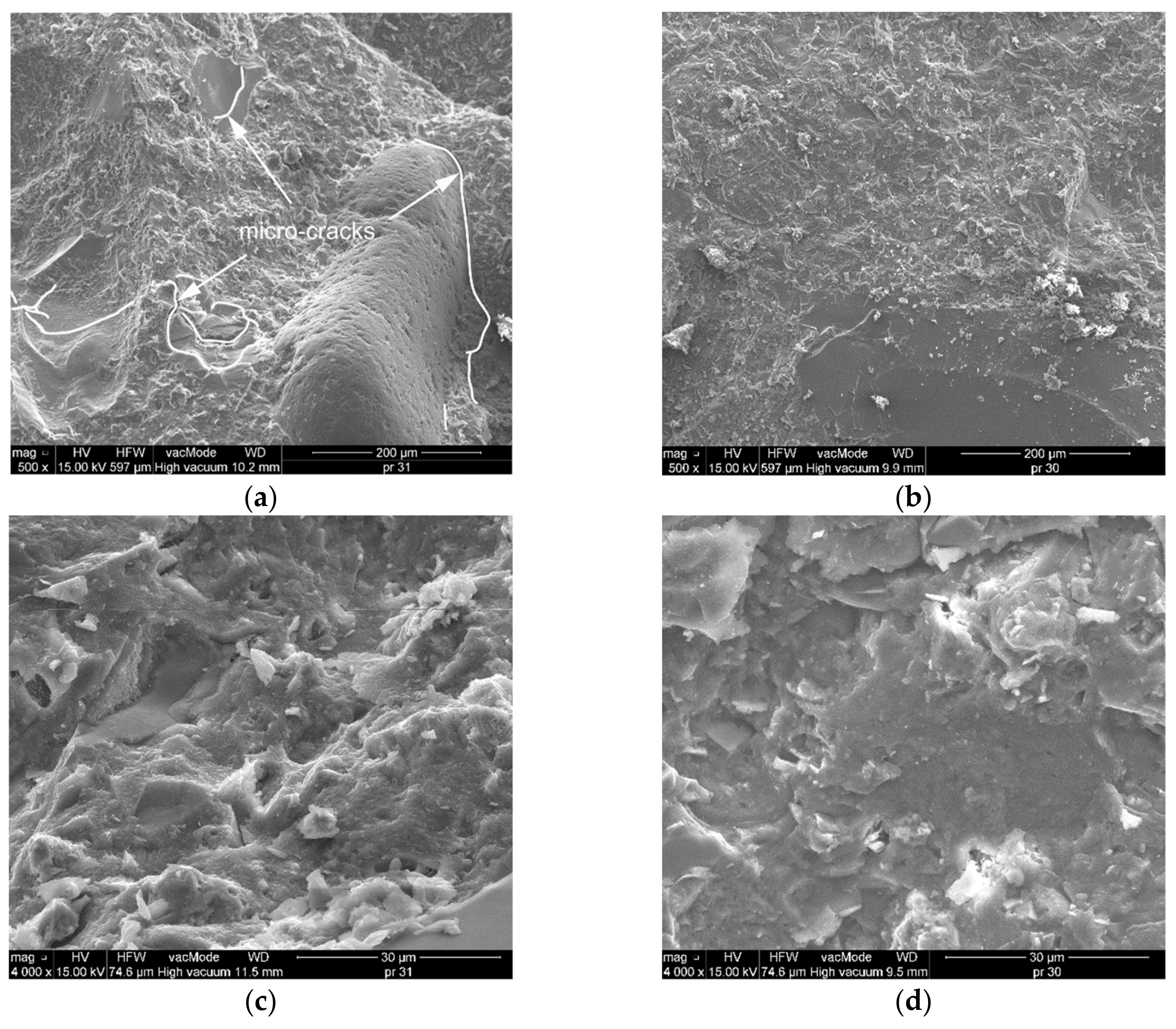
3.5. Microsturucture

Identification of the presence of various compounds and micro-cracks in the UHPC was performed using an FEI Quanta 250 FEG (Thermo Fisher Scientific, Hillsboro, Oregon, USA) scanning electron microscope (SEM).
The micrographs of the reference mixture, and with 5% WFS replacement are shown in Figure 6. The SEM micrographs were used to investigate the surface texture and morphology of UHPC. The 500× magnification SEM micrographs of the reference mixture (CWFS0) and the trial mixture with 5% WFS replacement (CWFS5) are presented in Figure 6a,b. These micrographs show the very compact microstructures of both mixtures. However, in the CWFS0 reference mix, small micro-cracks were observed at the aggregate and the cement matrix interface, which may induce a reduction in the UHPC strength (Figure 6a). The percentages of silica content in the quartz sand and WFS were 98% and 95.3% respectively. Figure 6 shows that the similar amount of SiO2 content generates well-formed material microstructures due to eliminating and filling the voids [49,50]. On the other hand, WFS contains 3.5 times more CaO than quartz sand.
The formation of calcium-silica-hydrate (C-S-H) gel was optimum in CWFS5. It is the most important phase present in the concrete, predominantly influenced by the size of the grains and the type of particle, phases composition, and porosity [12]. Figure 6d shows that the C-S-H gel is evenly distributed throughout the mixture and that the voids were significantly reduced in the mixture containing the 5% WFS replacement. In contrast, the SEM micrograph of the reference mixture (Figure 6c) shows that the C-S-H gel has extended to slightly less compared to the reference mix. This phase contributes to densification of the interfacial transition zone (ITZ) and reduced porosity up to 5% WFS, which helps to improve the mechanical properties of UHPC. As soon as the WFS was increased to 10% and 15% the surfaces did not show significant differences due to the relatively low WFS replacement level. A reduction in strengths was noted owning to excess fine particles and insoluble residues. This can be explained by the weaker bond strength of fine WFS particles, but it seems that the more important reason is the too many impurities present in the concrete with the higher WFS replacement level. According to Siddique and Noumowe [8], the reduced strengths in low-strength concrete can be due to the decrease in workability that can hamper mixture densification as well as the too numerous fine particles in WFS, which can settle on the surface of the aggregates and hinder the formation of a correct bond between the aggregate and the cement paste.
Aggarwal and Siddique [12] conducted a microstructural analysis of normal strength concrete made with WFS and discovered that C-S-H gel develops more extensively in specimens with a 10 or lower percentage of WFS substitution. However, this study also showed that at up to a 30% substitution of sand, large C-S-H gel formation occurred. A growth in strength was seen despite the fact that smaller C-S-H gel surfaces formed at higher levels of WFS replacement.

4. Conclusions

This investigation has established the possibility of utilizing WFS in UHPC as a replacement for quartz sand by assessing the physical and mechanical properties of UHPC. On the basis of the results of the compressive strength, flexural strength, splitting tensile strength, and modulus of elasticity tests performed on UHPC specimens made with 0%, 5%, 10%, and 15% WFS replacement, the following conclusions were reached:
  • The workability falls with a rise in WFS content. Therefore, the reduced workability affects the consolidation, fresh density, as well as the mechanical and physical properties of UHPC.
  • The compressive, splitting tensile, flexural strengths as well as elastic modulus of UHPC increase with 5% WFS replacement.
  • None of the tested properties of UHPC exhibit decreases more than 10% with a 10% WFS replacement.
  • The compressive, flexural, and splitting tensile strengths, as well as the elastic modulus of UHPC decrease in the specimens produced with 15% WFS.
  • Improvement in the microstructure of UHPC is observed due to the large C-S-H gel formation up to 5% WFS replacement. When the WFS level is increased a reduction in mechanical strength is noted because of excess WFS fine particles and insoluble residues.
  • Based on the results gathered in this study, the optimum replacement amount of WFS in UHPC is about 5% by weight of quartz sand.

Funding

This research was supported financially by the Polish Ministry of Science and Higher Education within statutory research project No. FN15/ILT/2019.

Acknowledgments

The financial support from the Polish Ministry of Science and Higher Education is greatly appreciated. The author would also like to thank the CEMEX company and the Iron Foundry in Lublin for donating the materials for this study.

Conflicts of Interest

The author declares that this article content has no conflict of interest.

References

  1. Foundry Industry Recycling Starts Today. Foundry Sand Facts for Civil Engineers; Technical Report No. FHWA-IF-04-004; EPA: Washington, DC, USA, 2004. [Google Scholar]
  2. Siddique, R.; Schutter, G.; Noumowe, A. Effect of used-foundry sand on the mechanical properties of concrete. Constr. Build. Mater. 2009, 23, 976–980. [Google Scholar] [CrossRef]
  3. Etxeberria, M.; Pacheco, C.; Meneses, J.M.; Berridi, I. Properties of concrete using metallurgical industrial by-products as aggregates. Constr. Build. Mater. 2010, 24, 1594–1600. [Google Scholar] [CrossRef]
  4. Siddique, R.; Singh, G. Utilization of waste foundry sand (WFS) in concrete manufacturing. Resour. Conserv. Recycl. 2011, 55, 885–892. [Google Scholar] [CrossRef]
  5. ABIFA. ABIFA 2016 Directory; Brazilian Foundry Association: Sao Paolo, Brazil, 2016. [Google Scholar]
  6. Żmudzińska, M.; Latała-Holtzer, M. Odpadowe masy formierskie—Możliwości ich utylizacji. Archiwum Odlewnictwa 2004, 4, 261–268. (In Polish) [Google Scholar]
  7. Dańko, J.; Dańko, R.; Łucarz, M. Procesy i Urządzenia do Regeneracji Osnowy Zużytych mas Odlewniczych; Wydawnictwo Naukowe AKAPIT: Kraków, Poland, 2007. (In Polish) [Google Scholar]
  8. Siddique, R.; Noumowe, A. Utilization of spent foundry sand in controlled low-strength materials and concrete. Resources, Conservation and Recycling 2008, 53, 27–35. [Google Scholar] [CrossRef]
  9. Guney, Y.; Sari, Y.D.; Yalcin, M.; Tuncan, A.; Donmez, S. Re-usage of waste foundry sand in high-strength concrete. Waste Manag. 2010, 30, 1705–1713. [Google Scholar] [CrossRef]
  10. Basar, H.M.; Aksoy, N.D. The effect of waste foundry sand (WFS) as partial replacement of sand on the mechanical, leaching and micro-structural characteristics of ready-mixed concrete. Constr. Build. Mater. 2012, 35, 508–515. [Google Scholar] [CrossRef]
  11. Prabhu, G.G.; Hyun, J.H.; Kim, Y.Y. Effects of foundry sand as a fine aggregate in concrete production. Constr. Build. Mater. 2014, 70, 514–521. [Google Scholar] [CrossRef]
  12. Aggarwal, Y.; Siddique, R. Microstructure and properties of concrete using bottom ash and waste foundry sand as partial replacement of fine aggregates. Constr. Build. Mater. 2014, 54, 210–223. [Google Scholar] [CrossRef] [Green Version]
  13. Siddique, R.; Singh, G.; Belarbi, R.; Ait-Mokhtar, K. Comparative investigation on the influence of spent foundry sand as partial replacement of fine aggregates on the properties of two grades of concrete. Constr. Build. Mater. 2015, 83, 216–222. [Google Scholar] [CrossRef]
  14. Bhardwaj, B.; Kumar, P. Waste foundry sand in concrete: A review. Constr. Build. Mater. 2017, 156, 661–674. [Google Scholar] [CrossRef]
  15. Manoharan, T.; Laksmanan, D.; Mylsamy, K.; Sivakumar, P. Engineering properties of concrete with partial utilization of used foundry sand. Waste Manag. 2018, 71, 454–460. [Google Scholar] [CrossRef] [PubMed]
  16. De Matos, P.R.; Marcon, M.F.; Schankoski, R.A.; Prudêncio, L.R., Jr. Novel applications of waste foundry sand in conventional and dry-mix concretes. J. Environ. Manag. 2019, 244, 294–303. [Google Scholar] [CrossRef] [PubMed]
  17. Balázs, G.L.; Bigaj-van Vliet, A.; Corres Peiretti, H.; Eligehausen, R.; Haist, M.; León, J.; Lima, L.J.; Müller, H.S.; Pérez Caldentey, A.; Randl, N.; et al. Structural Concrete: Textbook on Behaviour, Design and Performance, 2nd ed.; fib Bulletin No. 51; International Federation for Structural Concrete: Lausanne, Switzerland, 2009; Volume 1. [Google Scholar]
  18. Subcommittee C09.61 on Testing for Strength. Standard Specification for Fabricating and Testing Specimens of Ultra-High Performance Concrete; ASTM C1856/C1856-17; ASTM International: West Conshohocken, PA, USA, 2017. [Google Scholar] [CrossRef]
  19. Smarzewski, P. Effect of curing period on properties of steel and polypropylene fibre reinforced ultra-high performance concrete. IOP Conf. Ser. Mater. Sci. Eng. 2017, 245, 32059. [Google Scholar] [CrossRef]
  20. Shi, C.; Wu, Z.; Xiao, J.; Wang, D.; Huang, Z.; Fang, Z. A review on ultra high performance concrete: Part I. Raw materials and mixture design. Constr. Build. Mater. 2015, 101, 741–751. [Google Scholar] [CrossRef]
  21. Yoo, D.; Banthia, N. Mechanical properties of ultra-high-performance fiber-reinforced concrete: A review. Cem. Concr. Compos. 2016, 73, 267–280. [Google Scholar] [CrossRef]
  22. Yoo, D.Y.; Yoon, Y.S. A review on structural behavior, design, and application of ultra-high-performance fiber-reinforced concrete. Int. J. Concr. Struct. Mater. 2016, 10, 125–142. [Google Scholar] [CrossRef] [Green Version]
  23. Smarzewski, P. Study of toughness and macro/micro-crack development of fibre-reinforced ultra-high performance concrete after exposure to elevated temperature. Materials 2019, 12, 1210. [Google Scholar] [CrossRef] [Green Version]
  24. Abbas, S.; Nehdi, M.L.; Saleem, M.A. Ultra-high performance concrete: Mechanical performance, durability, sustainability and implementation challenges. Int. J. Concr. Struct. Mater. 2016, 10, 271–295. [Google Scholar] [CrossRef] [Green Version]
  25. Camacho, E.; López, J.Á.; Serna Ros, P. Definition of three levels of performance for UHPFRC-VHPFRC with available materials. In Ultra-High Performance Concrete and Nanotechnology in Construction; Kassel University Press: Kassel, Germany, 2012; pp. 249–256. [Google Scholar]
  26. Habel, K.; Viviani, M.; Denarié, E.; Brühwiler, E. Development of the mechanical properties of an Ultra-High Performance Fiber Reinforced Concrete (UHPFRC). Cem. Concr. Res. 2006, 36, 1362–1370. [Google Scholar] [CrossRef]
  27. Bøhnsdalen Eide, M.; Hisdal, J.-M. Ultra High Performance Fibre Reinforced Concrete (UHPFRC)—State of the Art; COIN Project report 44—2012; SINTEF Building and Infrastructure: Oslo, Norway, 2012. [Google Scholar]
  28. Yang, J.; Peng, G.-F.; Gao, Y.-X.; Zhang, H. Characteristics of mechanical properties and durability of ultra-high performance concrete incorporating coarse aggregate. In Ultra-High Performance Concrete and Nanotechnology in Construction; Kassel University Press: Kassel, Germany, 2012; pp. 257–264. [Google Scholar]
  29. Wang, C.; Yang, C.; Liu, F.; Wan, C.; Pu, X. Preparation of ultra-high performance concrete with common technology and materials. Cem. Concr. Compos. 2012, 34, 538–544. [Google Scholar] [CrossRef]
  30. Torres, A.; Aguayo, F.; Allena, S.; Ellis, M. Mechanical properties of ultra high performance fiber reinforced concrete made with foundry sand. J. Civ. Eng. Constr. 2019, 8, 157–167. [Google Scholar] [CrossRef]
  31. Polish Committee for Standardization. PN-EN 197-1. Cement. Composition, Specifications and Conformity Criteria for Common Cements. 2012. Available online: http://sklep.pkn.pl/pn-en-197-1-2012p.html (accessed on 20 September 2019).
  32. Polish Committee for Standardization. PN-B-19707:2013-10. Cement. Special Cement. Composition, Specifications and Conformity Criteria. 2013. Available online: http://sklep.pkn.pl/pn-b-19707-2013-10p.html (accessed on 20 September 2019).
  33. Sahmaran, M.; Lachemi, M.; Erdem, T.K.; Yucel, H.E.; Yu, H.E. Use of spent foundry sand and fly ash for the development of green self-consolidating concrete. Mat. Struct. 2011, 44, 1193–1204. [Google Scholar] [CrossRef] [Green Version]
  34. Khatib, J.M.; Herki, B.A.; Kenai, S. Capillarity of concrete incorporating waste foundry sand. Constr. Build. Mater. 2013, 47, 867–871. [Google Scholar] [CrossRef]
  35. Monosi, S.; Tittarelli, F.; Giosuè, C.; Ruello, M.L. Effect of two different sources and washing treatment on the properties of UFS by-products for mortar and concrete production. Constr. Build. Mater. 2013, 44, 260–266. [Google Scholar] [CrossRef]
  36. Polish Committee for Standardization. PN-EN 933-1. Tests for Geometrical Properties of Aggregates. Determination of Particle Size Distribution. Sieving Method. 2012. Available online: http://sklep.pkn.pl/pn-en-933-1-2012e.html (accessed on 20 September 2019).
  37. Shaheen, E.; Shrive, N.J. Optimization of mechanical properties and durability of reactive powder concrete. ACI Mater. J. 2006, 103, 444–451. [Google Scholar] [CrossRef]
  38. Smarzewski, P. Influence of silica fume on mechanical and fracture properties of high performance concrete. Procedia Struct. Integr. 2019, 17, 5–12. [Google Scholar] [CrossRef]
  39. Smarzewski, P. Influence of basalt-polypropylene fibres on fracture properties of high performance concrete. Compos. Struct. 2019, 209, 23–33. [Google Scholar] [CrossRef]
  40. Polish Committee for Standardization. PN-EN 12390-7. Testing Hardened Concrete, Density of Hardened Concrete. 2011. Available online: http://sklep.pkn.pl/pn-en-12390-7-2011p.html (accessed on 20 September 2019).
  41. Polish Committee for Standardization. PN-EN 13755. Natural Stone Test Methods. Determination of Water Absorption at Atmospheric Pressure. 2008. Available online: http://sklep.pkn.pl/pn-en-13755-2008e.html (accessed on 20 September 2019).
  42. Polish Committee for Standardization. PN-EN 12390-3. Testing Hardened Concrete. Compressive Strength of Test Specimens. 2011. Available online: http://sklep.pkn.pl/pn-en-12390-3-2011p.html (accessed on 20 September 2019).
  43. de Matos, P.R.; de Oliveira, A.L.; Pelisser, F.; Prudêncio, L.R. Rheological behavior of Portland cement pastes and self-compacting concretes containing porcelain polishing residue. Constr. Build. Mater. 2018, 175, 508–518. [Google Scholar] [CrossRef]
  44. Berodier, E.; Scrivener, K. Understanding the filler effect on the nucleation and growth of C-S-H. J. Am. Ceram. Soc. 2014, 97, 3764–3773. [Google Scholar] [CrossRef]
  45. Leemann, A.; Lura, P.; Loser, R. Shrinkage and creep of SCC—The influence of paste volume and binder composition. Constr. Build. Mater. 2011, 25, 2283–2289. [Google Scholar] [CrossRef] [Green Version]
  46. Polish Committee for Standardization. PN-EN 12390-6. Testing Hardened Concrete. Tensile Splitting Strength of Test Specimens. 2011. Available online: http://sklep.pkn.pl/pn-en-12390-6-2011p.html (accessed on 20 September 2019).
  47. Polish Committee for Standardization. PN-EN 12390-5. Testing Hardened Concrete. Flexural Strength of Test Specimens. 2011. Available online: http://sklep.pkn.pl/pn-en-12390-5-2011p.html (accessed on 20 September 2019).
  48. ASTM. C469/C469M-14 Standard Test Method for Static Modulus of Elasticity and Poisson’s Ratio of Concrete in Compression; ASTM International: West Conshohocken, PA, USA, 2014. [Google Scholar] [CrossRef]
  49. Hewlett, P.C. Lea’s Chemistry of Cement and Concrete, 4th ed.; Butterworth-Heinemann: Oxford, UK, 2003. [Google Scholar] [CrossRef]
  50. Yazici, H. Utilization of coal combustion byproducts in building blocks. Fuel 2007, 86, 929–937. [Google Scholar] [CrossRef]
Figure 1. (a) Foundry sand as mould in iron casting; (b) Microstructure of waste foundry sand (WFS).
Buildings 10 00011 g001
Figure 2. Compressive strength results.
Buildings 10 00011 g002
Figure 3. Splitting tensile strength results.
Buildings 10 00011 g003
Figure 4. Flexural strength results.
Buildings 10 00011 g004
Figure 5. Modulus of elasticity results.
Buildings 10 00011 g005
Figure 6. SEM micrographs of UHPC specimens. (a) Reference mixture (mag. 500×); (b) 5% replacement of WFS (mag. 500×); (c) Reference mixture (mag. 4000×); (d) 5% replacement of WFS (mag. 4000×).
Buildings 10 00011 g006
Table 1. Physical properties of cement.
Material CharacteristicsCement
Specific surface area (m2/kg)443
Water demand (%)30
Start of setting (min)120
End of setting (min)180
Volume stability acc. to Le Chateliere (mm)2
Compressive strength at 2 days (N/mm2)27.7
Compressive strength at 28 days (N/mm2)57.1
Tensile strength at 2 days (N/mm2)5.3
Tensile strength at 28 days (N/mm2)8.2
Table 2. Chemical composition of cement and silica fume (in %).
CompoundCementSilica Fume
SiO220.9294.80
Al2O33.501.30
Fe2O34.380.83
CaO64.690.56
MgO1.200.71
SO33.07NA
K2O0.381.26
Na2O0.220.41
Cl0.08NA
Loss on ignition1.270.12
Insoluble matter0.20NA
Table 3. Physical properties of basalt aggregate, quartz sand, and waste foundry sand (WFS).
Material CharacteristicsBasaltQuartz SandWaste Foundry Sand
Unit weight (kg/m3)308615851521
Specific gravity2.952.672.45
Absorption (%)0.21.121.4
Fineness modulus5.921.841.80
Compressive strength (N/mm2)196
Table 4. Chemical composition of basalt aggregate, quartz sand and WFS (in %).
CompoundBasaltQuartz SandWaste Foundry Sand
SiO242.8698.095.3
Al2O311.460.81.9
Fe2O313.420.20.7
CaO11.130.10.35
MgO9.71
SO30.01
Na2O2.93
K2O0.89
P2O50.64
TiO22.360.8
MnO0.21
Table 5. Different chemical compositions of WFS (in %).
CompoundEtxeberria
et al. [3]
Guney
et al. [9]
Sahmaran
et al. [33]
Basar
et al. [10]
Khatib
et al. [34]
Smarzewski
[This Study]
SiO284.9098.0076.0081.8587.9195.30
Al2O35.210.804.4510.414.701.90
Fe2O33.220.255.061.820.940.70
CaO0.580.043.561.210.140.35
MgO0.670.021.981.970.30
SO30.290.010.840.09
Na2O0.500.040.380.760.19
K2O0.970.041.200.490.25
P2O50.050.05
TiO20.190.17
Mn2O30.080.010.46
Cr2O30.37
LOI2.875.856.935.15
Table 6. Ultra-high performance concrete (UHPC) mixture proportion and properties of fresh concrete.
DesignationCWFS0CWFS5CWFS10CWFS15
Cement (kg/m3)670.5670.5670.5670.5
Silica fume (kg/m3)74.574.574.574.5
Quartz sand (kg/m3)500475450425
Waste foundry sand (kg/m3)0255075
WFS content (%)051015
Basalt (kg/m3)990990990990
Water (l/m3)178178178178
Superplasticizer (l/m3)20202020
Slump (mm)120118115111
Unite weight (kg/m3)2434243224292425
Note: CWFS0 = control concrete; CWFSa = concrete with WFS, where a = waste foundry sand content (in %).
Table 7. Specimens specifications.
TestShapeDimensions (mm)Number
CompressionCube100 × 100 × 10048
Splitting tensileCube100 × 100 × 10048
FlexuralBeam50 × 50 × 25048
Modulus of elasticityCylinder150 × 30048
Table 8. Physical properties.
DesignationCWFS0CWFS5CWFS10CWFS15
Apparent density (g/cm3)2.422.422.442.48
Standard deviation (g/cm3)0.020.020.020.03
Absorbability (%)3.112.982.782.70
Standard deviation (%)0.040.040.030.03
Open porosity (%)7.587.206.886.58
Standard deviation (%)0.080.070.080.06

