The Optimum Process to Produce High-Strength Cast/Forged Al–8%Zn–2.5%Mg–1%Cu Alloy

Abstract
:
1. Introduction
2. Materials and Methods
3. Results and Discussion
4. Conclusions
Author Contributions
Funding
Acknowledgments
Conflicts of Interest
References
- Abolhasani, A.; Zarei-Hanzaki, A.; Abedi, H.R.; Rokni, M.R. The room temperature mechanical properties of hot rolled 7075 aluminum alloy. Mater. Des. 2012, 34, 631–636. [Google Scholar] [CrossRef]
- Ou, B.-L.; Yang, J.-G.; Yang, C.-K. Effects of step-quench and aging on mechanical properties and resistance to stress corrosion cracking of 7050 aluminum alloy. Mater. Trans. 2000, 41, 783–789. [Google Scholar] [CrossRef]
- Wang, D.; Ma, Z.Y.; Gao, Z.M. Effects of severe cold rolling on tensile properties and stress corrosion cracking of 7050 aluminum alloy. Mater. Chem. Phys. 2009, 117, 228–233. [Google Scholar] [CrossRef]
- Magalhães, D.C.C.; Hupalo, M.F.; Cintho, O.M. Natural aging behavior of AA7050 Al alloy after cryogenic rolling. Mater. Sci. Eng. A 2014, 93, 1–7. [Google Scholar]
- Knight, S.P.; Pohl, K.; Holroyd, N.J.H.; Birbilis, N.P.; Rometsch, A.; Muddle, B.C.; Goswami, R.S.; Lynch, P. Some effects of alloy composition on stress corrosion cracking in Al-Zn-Mg-Cu alloys. Corros. Sci. 2015, 98, 50–62. [Google Scholar] [CrossRef]
- Monda, L.C.; Mukhopadhyay, A.K. On the nature of T(Al2Mg3Zn3) and S(Al2CuMg) phases present in as-cast and annealed 7055 aluminum alloy. Mater. Sci. Eng. A 2005, 391, 367–376. [Google Scholar] [CrossRef]
- Sha, G.; Cerezo, A. Early-stage precipitation in Al-Zn-Mg-Cu alloy (7050). Acta Mater. 2004, 52, 4503–4516. [Google Scholar] [CrossRef]
- Li, J.-F.; Peng, Z.-W.; Li, C.-X.; Jia, Z.-Q.; Chen, W.-J.; Zheng, Z.-Q. Mechanical properties, corrosion behaviors and microstructures of 7075 aluminium alloy with various aging treatments. Trans. Nonferrous. Met. Soc. China 2008, 18, 755–762. [Google Scholar] [CrossRef]
- Mahathaninwong, N.; Plookphol, T.; Wannasin, J.; Wisutmethangoon, S. T6 heat treatment of rheocasting 7075 Al alloy. Mater. Sci. Eng. A 2012, 532, 91–99. [Google Scholar] [CrossRef]
- Ber, L.B. Accelerated artificial ageing regimes of commercial aluminium alloys. II: Al-Cu, Al-Zn-Mg-(Cu), Al-Mg-Si-(Cu) alloys. Mater. Sci. Eng. A 2000, 280, 91–96. [Google Scholar] [CrossRef]
- Shih, T.-S.; Liao, T.-W.; Hsu, W.-N. Effects of Cryogenic Forging and Anodization on the Mechanical Properties of AA 7075-T73 Aluminum Alloys. J. Mater. Eng. Perform. 2016, 25, 1211–1218. [Google Scholar] [CrossRef]
- Shih, T.-S.; Yong, H.-S.; Hsu, W.-N. Effects of cryogenic forging and anodization on the mechanical properties and corrosion resistance of AA6066-T6 Aluminum alloys. Metals 2016, 6, 51. [Google Scholar] [CrossRef]
- Shih, T.-S.; Lin, J.-W. Mechanical properties and fatigue behavior of cast/forged Al-1.2%Mg-1.0%Si-1.0%Cu Aluminum alloys. Mater. Trans. 2018, 59, 1130–1134. [Google Scholar] [CrossRef]
- Fujikawa, S.; Kitamura, Y.; Shimamura, S. Application of numerical methods for the aluminum casting/forging process. J. Mater. Process. Technol. 1991, 27, 93–110. [Google Scholar] [CrossRef]
- Chang, F.C.; Hwang, W.S.; Lee, C.H.; Wu, C.F.; Yang, J.B. Forging condition for removing porosities in the hybrid casting and forging process of 7075 Aluminum alloy casting. Mater. Trans. 2004, 45, 1886–1890. [Google Scholar] [CrossRef]
- Yang, Y.; Zhang, Z.; Li, X.; Wang, Q.; Zhang, Y. The effects of grain size on the hot deformation and processing map for 7075 aluminum alloy. Mater. Des. 2013, 51, 592–597. [Google Scholar] [CrossRef]
- Deng, Y.-L.; Zhang, Y.-Y.; Li, W.; Zhu, A.A.; Zhang, X.-M. Three-stage homogenization of Al-Zn-Mg-Cu alloys containing trace Zr. Metall. Mater. Trans. A 2013, 44, 2470–2477. [Google Scholar] [CrossRef]
- Shih, T.-S.; Chiu, Y.-W. Corrosion resistance and high-cycle fatigue strength of anodized/sealed AA7050 and AA7075 alloys. Appl. Surf. Sci. 2015, 351, 997–1003. [Google Scholar] [CrossRef]
- Huang, Y.-S.; Shih, T.-S.; Chou, J.-H. Electrochemical behavior of anodized AA7075-T73 alloys as affected by the matrix structure. Appl. Surf. Sci. 2013, 283, 249–257. [Google Scholar] [CrossRef]
- Muzyk, M.; Pakiela, Z.; Kurzydlowski, K.J. Ab initio calculations of the generalized stacking fault energy in aluminum alloys. Scr. Mater. 2011, 64, 916–918. [Google Scholar] [CrossRef]
- Jonas, J.J.; Quelennec, X.; Jiang, L.; Martin, É. The Avrami kinetics of dynamic recrystallization. Acta Mater. 2009, 57, 2748–2756. [Google Scholar] [CrossRef]
- Feng, D.; Wang, G.; Chen, H.; Zhang, X.M. Effect of grain size inhomogeneity of ingot on dynamic softening behavior and processing map of Al-8Zn-2Mg-2Cu alloy. Met. Mater. Int. 2018, 24, 195–204. [Google Scholar] [CrossRef]
- Feng, D.; Zhang, X.M.; Liu, S.D.; Deng, Y.L. Constitutive equation and hot deformation behavior of homogenized Al–7.68Zn–2.12Mg–1.98Cu–0.12Zr alloy during compression at elevated temperature. Mater. Sci. Eng. A 2014, 608, 63–72. [Google Scholar] [CrossRef]
- Fan, X.-G.; Jiang, D.-M.; Meng, Q.-C.; Zhang, B.-Y.; Wang, T. Evolution of eutectic structures in Al-Zn-Mg-Cu alloys during heat treatment. Trans. Nonferrous Met. Soc. China 2006, 16, 577–581. [Google Scholar] [CrossRef]


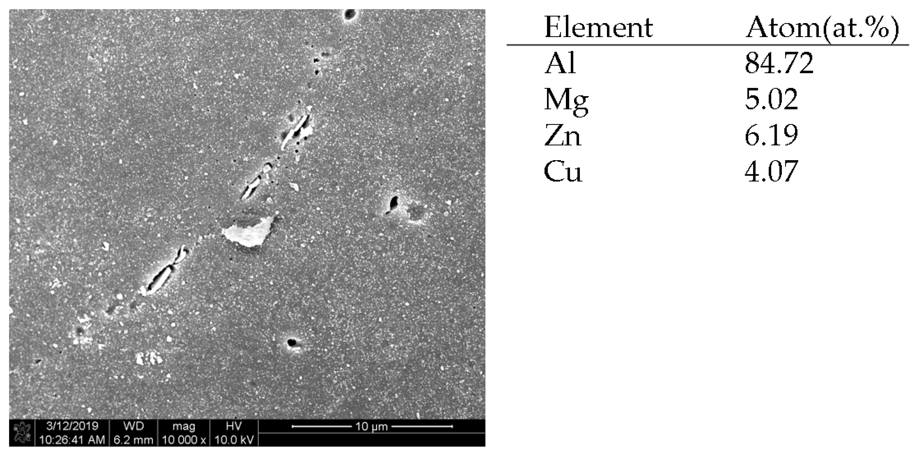
| Element | Si | Fe | Cu | Mn | Mg | Cr | Zn | Ti | Zr |
|---|---|---|---|---|---|---|---|---|---|
| Content | 0.07 | 0.15 | 1.65 | 0.04 | 2.42 | 0.21 | 8.39 | 0.02 | 0.18 |
| Sample Code | UTS (MPa) | YS (MPa) | TEl. (%) |
|---|---|---|---|
| HC: Avg./SD | 508.2/33.4 | 440.2/46.8 | 4.2/1.3 |
| SO: Avg./SD | 484/1.4 | 406.8/4.7 | 11.8/2.4 |
| Poisson Ratio | n | K (MPa) | CTE (CD) (1/K) | CTE (OD)(1/K) | Cp (J/kg—K) | q (W/m—K) |
|---|---|---|---|---|---|---|
| 0.33 | 0.17 | 400 | 2.52 × 10⁻⁶ | 2.16 × 10⁻⁶ | 960 | 173 |
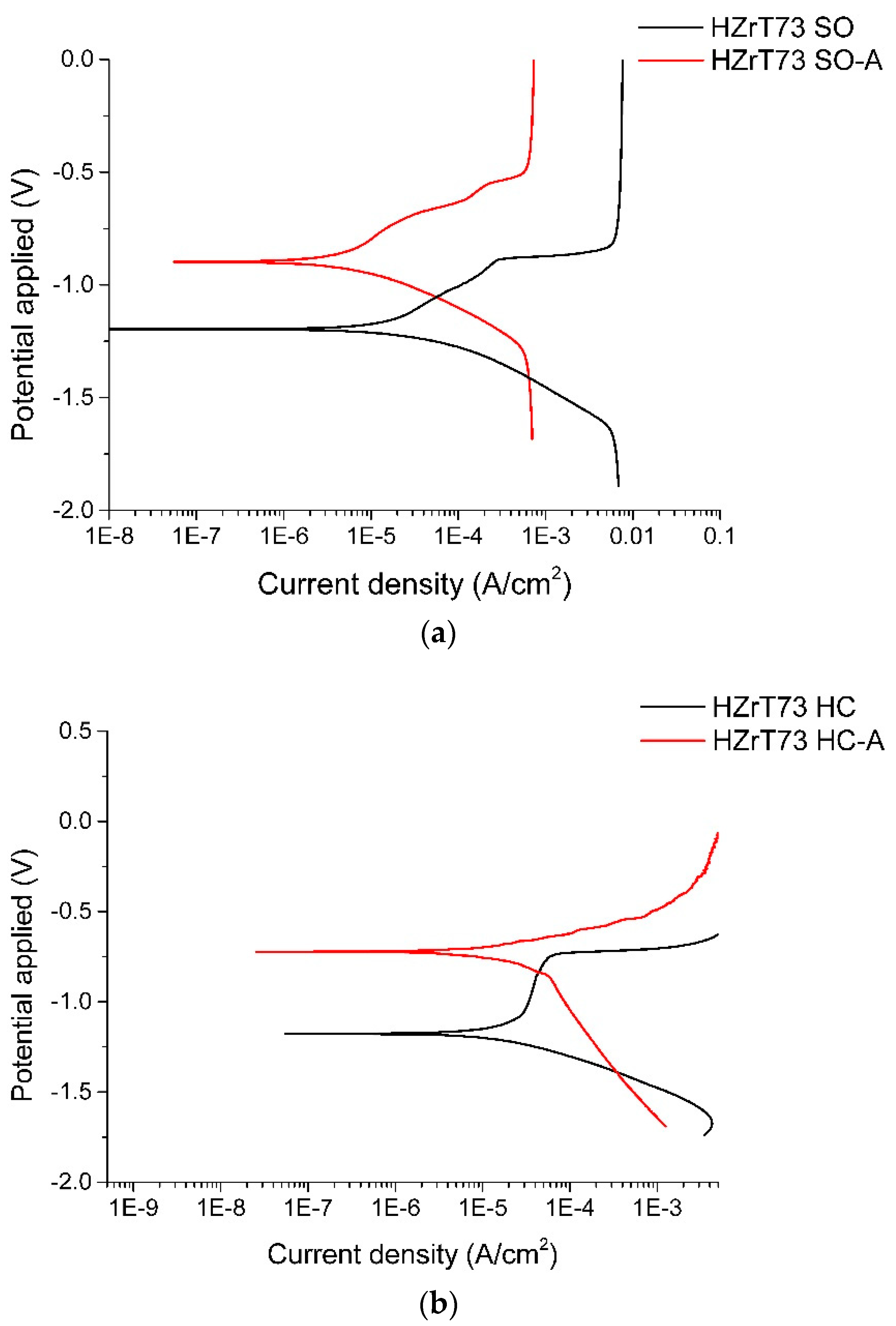
| Sample Code | Ecorr (V) | Icorr (A/cm2) | Epit (V) | Ipit (A/cm2) |
|---|---|---|---|---|
| HC | −1.30 (0.18) | 2.59 (1.49) × 10−6 | −0.75 (0.03) | 4.35 (1.15) × 10−5 |
| HC-A | −0.74 (0.04) | 7.97 (1.76) × 10−7 | None visible | None visible |
| SO | −1.13 (0.06) | 4.40 (0.42) × 10−6 | −0.79 (0.01) | 3.4 (1.13) × 10−4 |
| SO-A | −0.91 (0.02) | 3.29 (1.07) × 10−6 | None visible | None visible |
© 2019 by the authors. Licensee MDPI, Basel, Switzerland. This article is an open access article distributed under the terms and conditions of the Creative Commons Attribution (CC BY) license (http://creativecommons.org/licenses/by/4.0/).
Share and Cite
Shih, T.-S.; Kwang, E.-T.; Huang, Y.-S. The Optimum Process to Produce High-Strength Cast/Forged Al–8%Zn–2.5%Mg–1%Cu Alloy. Metals 2019, 9, 970. https://doi.org/10.3390/met9090970
Shih T-S, Kwang E-T, Huang Y-S. The Optimum Process to Produce High-Strength Cast/Forged Al–8%Zn–2.5%Mg–1%Cu Alloy. Metals. 2019; 9(9):970. https://doi.org/10.3390/met9090970
Chicago/Turabian StyleShih, Teng-Shih, Ei-Ting Kwang, and Yung-Sen Huang. 2019. "The Optimum Process to Produce High-Strength Cast/Forged Al–8%Zn–2.5%Mg–1%Cu Alloy" Metals 9, no. 9: 970. https://doi.org/10.3390/met9090970