Article

Investigation on Springback Behavior of Cu/Ni Clad Foils during Flexible Die Micro V-Bending Process

School of Materials Science and Engineering, Harbin Institute of Technology at Weihai, Weihai 264209, China
*
Author to whom correspondence should be addressed.
Metals 2019, 9(8), 892; https://doi.org/10.3390/met9080892
Submission received: 4 July 2019 / Revised: 8 August 2019 / Accepted: 13 August 2019 / Published: 15 August 2019
(This article belongs to the Special Issue Clad Metals: Fabrication, Properties and Applications)

Abstract

:
With the increasing demand for micro parts using metal laminates in modern production, the manufacturing processes of thin sheet parts have been elevated. However, it is difficult to predict the deformation behavior with miniaturization because of size effects in micro-scale. In this study, the flexible die micro V-bending behavior of Cu/Ni clad foils was investigated. The bending experiments with three different punch angles and Cu/Ni clad foils under different annealed temperatures were performed. The results show that the springback angle increases with the increase of bending angle and annealing temperature. The placement of Cu/Ni clad foils induced compressive stress results in the more obvious thinning of thickness and decreasing of springback angle. The interactive effects of the distribution of deformation zones and compressive stress induced by the interface layer result in the springback behavior of Cu/Ni clad foils during the flexible die micro V-bending process.

1. Introduction

With the development of products toward miniaturization and complex function, monolayer metal or alloy gradually fails to meet the demand for comprehensive properties of materials in modern production [1,2]. Clad metals are widely used in various fields because of their good comprehensive performance and superior cost performance [3]. In comparison with the micro-machining and other micro-manufacturing technologies, micro-forming is one of the most suitable and economical manufacturing processes for mass production of micro-metal components [4]. However, the conventional understanding and the established knowledge of material deformation behaviors in macro-forming are no longer valid or accurate in micro-forming due to the occurrence of size effects [5].
Leu [6] developed a material constitutive model to distinguish the tensile flow stress of metal sheets from the micro-scale to the macro-scale. Zhao et al. [7] carried out micro-tensile experiments on magnesium alloy foils with different thickness and grain size, and the results showed an obvious size effect on flow stress. Subsequently, they introduced the size factor (t/d) parameter into the Swift constitutive model and constructed the constitutive model of magnesium alloy foils considering size effects. Tensile properties and fracture characteristics of high purity polycrystalline Ni were investigated using micro-tensile specimens [8]. Li et al. [9] successfully formed micro-arrayed deep drawn parts fabricated from Ni–Co/GO (graphene oxide) nanocomposite foils.
The micro-bending of foils is a fundamental materials test to underpin strain gradient plasticity theories [10]. Micro-bending experiments of brass foils were conducted and the results demonstrated obvious size effects on the springback angle, i.e., the normalized bending moment increased with the reduction of foil thickness [11]. To analyze the flow stress size effect, a simplified constitutive model was proposed, which took into account the plastic strain gradient hardening, and was applied to predict the non-dimensional bending moment and the springback angle after micro-bending [12]. The final dimension of metal foil is significantly affected by the springback behavior, which becomes even more complicated during the micro-bending [4]. The influences of grain size and thickness on the springback of foils were investigated. The bending force decreases with the decrease in thickness. The decrease of the cross-sectional area and the increase of free surface effect are the main reasons [13]. Wang et al. [14] used C2680 brass foil to carry out three-point micro-bending orthogonal experiments. It was found that the thickness of blank has an obvious effect on springback. Liu et al. [15] proposed that the decrease of sheet thickness or the increase of grain size results in a large angle of springback. Grain refinement induced brittle behavior with higher elastic modulus and smaller plasticity, which may contribute to the higher springback amount [16]. The reduction of yield strength and flow stress is revealed to be the major reason for the reduction of springback angle with the increase of grain size [17]. The obvious size effect is attributed to plastic strain gradient hardening [18]. Wang et al. [19] found that the springback of the ultra-thin sheet in micro-bending was affected by the friction conditions, bending angle, and forming rate. Chen et al. [20] found that the springback decreased with the increase of bending angle of the die. V-shaped dies are used for micro-bending to form bent specimens with different angles. Bao et al. [21] designed bending dies with angles of 30°, 60°, and 90°. Wang et al. [22] used the rubber as the flexible punch and discussed the influence of grain structure and grain size. Although there are many studies on the micro-bending of monolayer metal sheets, there are few studies on the micro-bending of clad sheets, especially for clad foils. Kim et al. [23] explored the effect of heat treatment temperature on the Cu/Al/Cu three-layer composite sheet. Shayan et al. [24] found that the effect of the thickness of the single-layer had little effect on the springback. Yilamu et al. [25] discovered that the placement of the specimen had an effect on the bending behavior and sheet thinning. The effects of the hardening model on the accuracy of springback prediction were also studied. It can be known that the thickness of the sheet may increase when the softer layer is faced with the punch. The quantitative predicting of springback is very important for the metal sheets to achieve the desired final part geometry, especially for the miniaturized components. An advanced analytical formulation was developed to predict the thickness change of an Al/Cu clad sheet [26]. Li et al. [12] investigated the micro-bending of CuZn37 brass foil and proposed a strain gradient hardening model considering twinning. Gau et al. [27] concluded that the springback amount of brass could be expressed as a function of t/d when its thickness is less than 350 µm by the three-point bending experiment. Zhang et al. [28] predicted the springback based on the second Hill yield criterion considering the sheet thinning, transverse stress, and punch contact pressure. Only a few studies on Cu/Ni clad foil have been reported because of the complexity of deformation properties of clad foils currently. Additionally, flexible die forming has the advantages of eliminating surface scratches in the sheet metal forming process and reducing production costs. The use of flexible die can also reduce springback in the bending process [29]. Therefore, it is of great theoretical significance and application value to research the flexible die micro-bending process of Cu/Ni clad foils. In the present study, the effects of material parameters, placement modes, and die structures on the micro-bending process and springback of Cu/Ni clad foil were analyzed through experiments and finite element simulation.

2. Materials and Methods

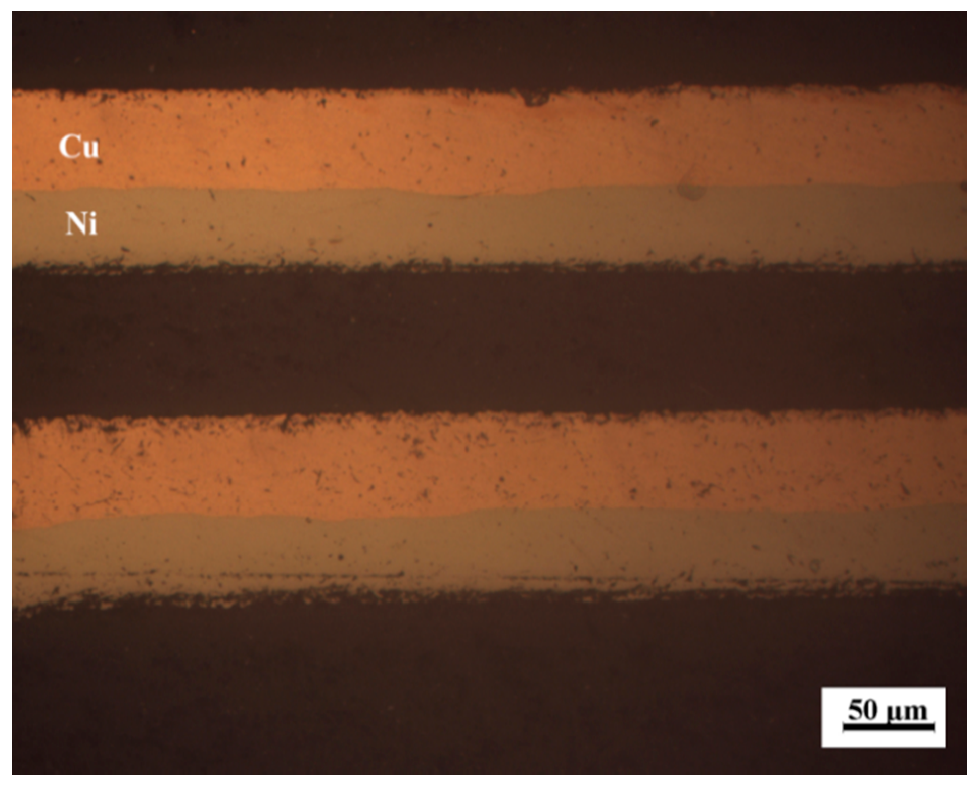
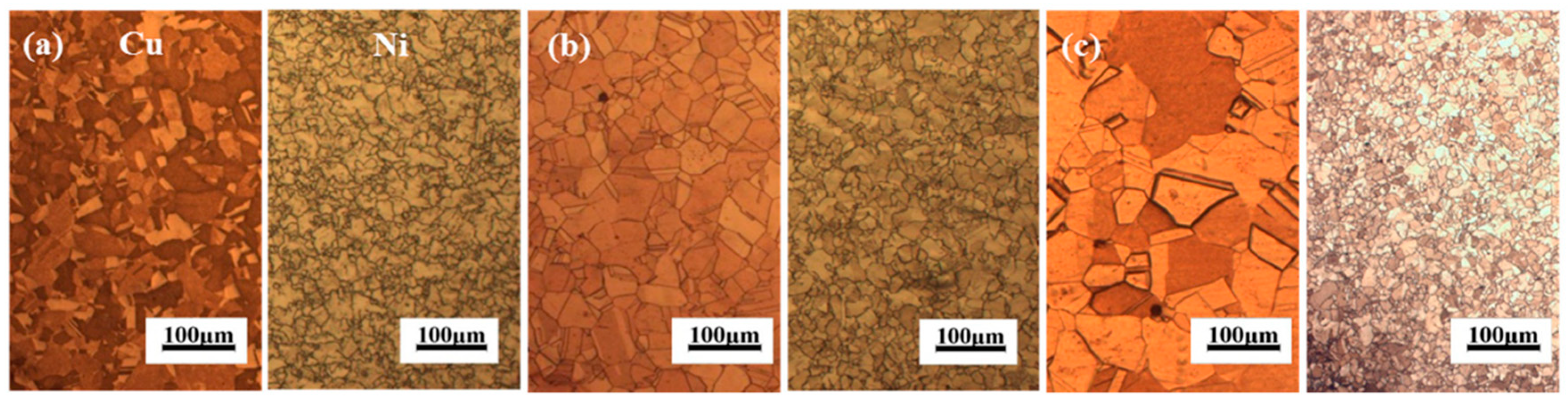
2.1. Experimental Materials

Cu/Ni clad foils with a thickness of 100 μm and a thickness ratio of Cu to Ni of 1.25:1 were employed as the testing materials in this research. The detailed manufacturing process of Cu/Ni clad foil is that Cu and Ni plates had initially 1.5 mm thickness approximately, and then it was rolled down to 0.1 mm after three rolling steps. After each rolling step, the clad foils were annealed in 500~600 °C. The length of the rectangle specimens is 20 mm and the width is 5 mm. The specimen cross-section along the rolling direction (RD) was observed under a microscope, as shown in Figure 1.
To eliminate the work hardening and improve the forming ability, the specimens were annealed at 600 °C, 700 °C, and 850 °C for 1 h, respectively. Microstructures of the billets along RD at different annealing temperatures are shown in Figure 2. Complete recrystallization occurred in both copper and nickel layers after annealing. The annealed grains are equiaxed. The grain sizes of the copper and nickel layers are obtained from the rolling direction and measured by the linear intercept method. The component thicknesses were measured by SEM (MERLIN Compact, Carl Zeiss AG, Heidenheim, Germany). The grain sizes and thicknesses of each component of the billet are listed in Table 1. The grain sizes of copper and nickel layers increase with the annealing temperature. The thickness of the interface layer increases with the annealing temperature. In contrast, the thickness of copper and nickel layers decreases accordingly with the annealing temperature.

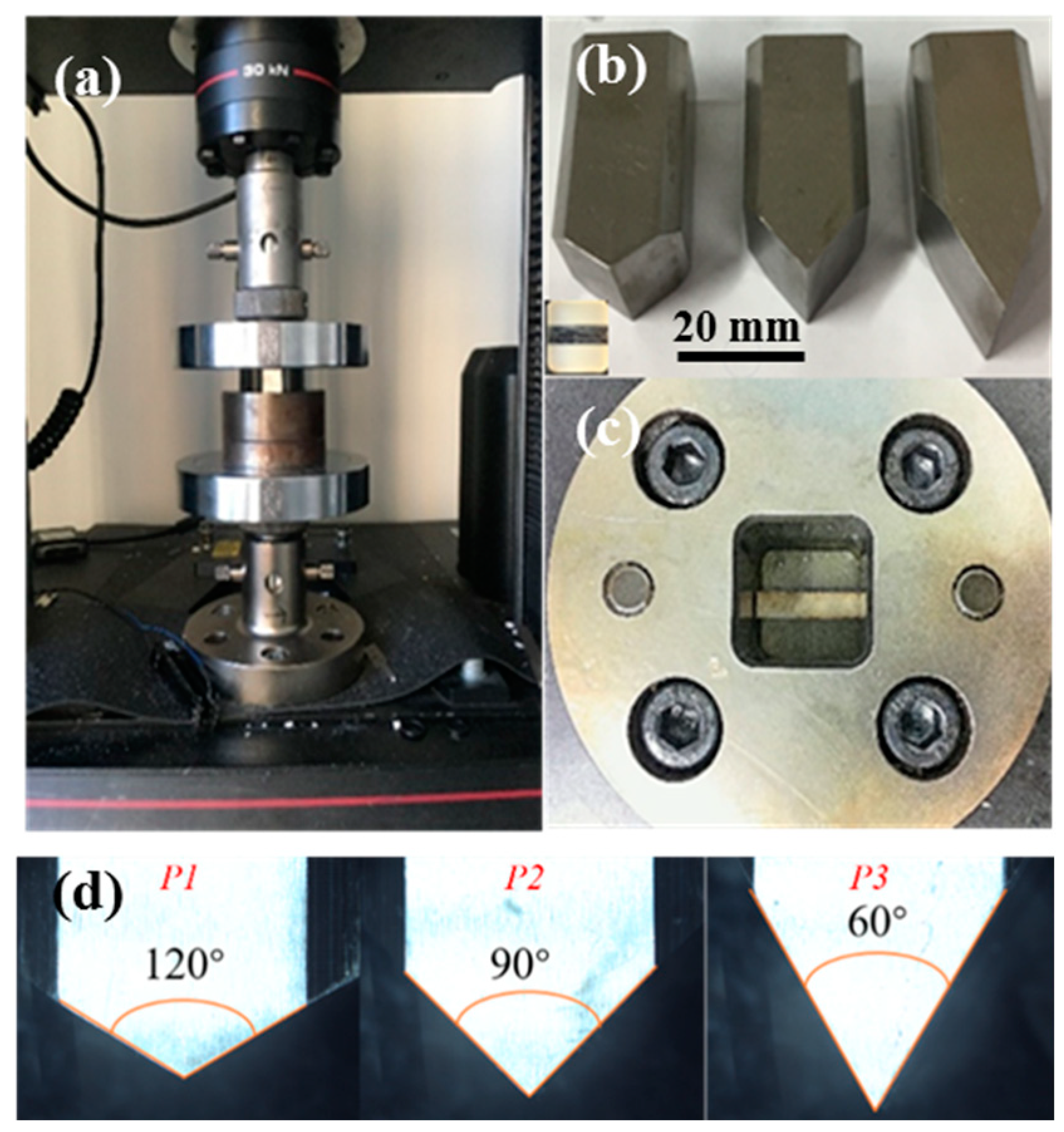
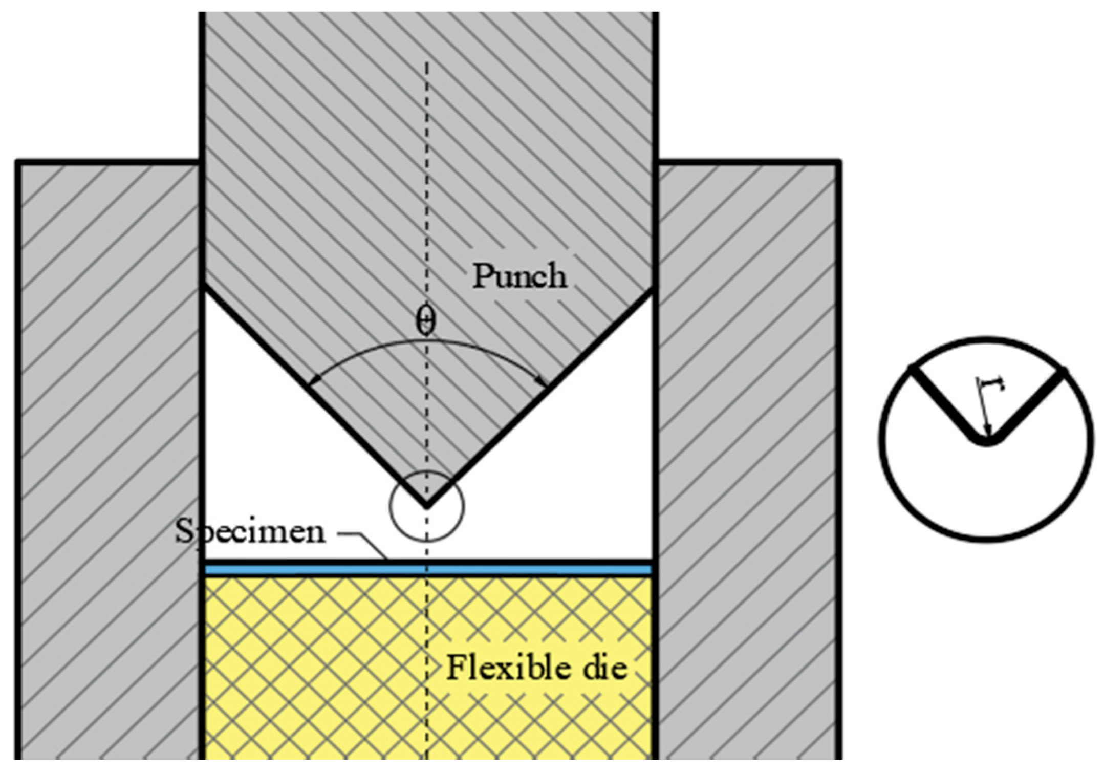
2.2. Experimental Setup

The setup of the micro V-bending experiment and three rigid punches with different bending angles are shown in Figure 3. Three punch angles are expressed by P1 (α1 = 60°, θ = 120°, r = 0.1 mm), P2 (α2 = 90°, θ = 90°, r = 0.1 mm), P3 (α3 = 120°, θ = 60°, r = 0.1 mm), which are shown in Figure 3d. α is bending angle, θ is punch angle, and α + θ = 180°. r is punch fillet radius.

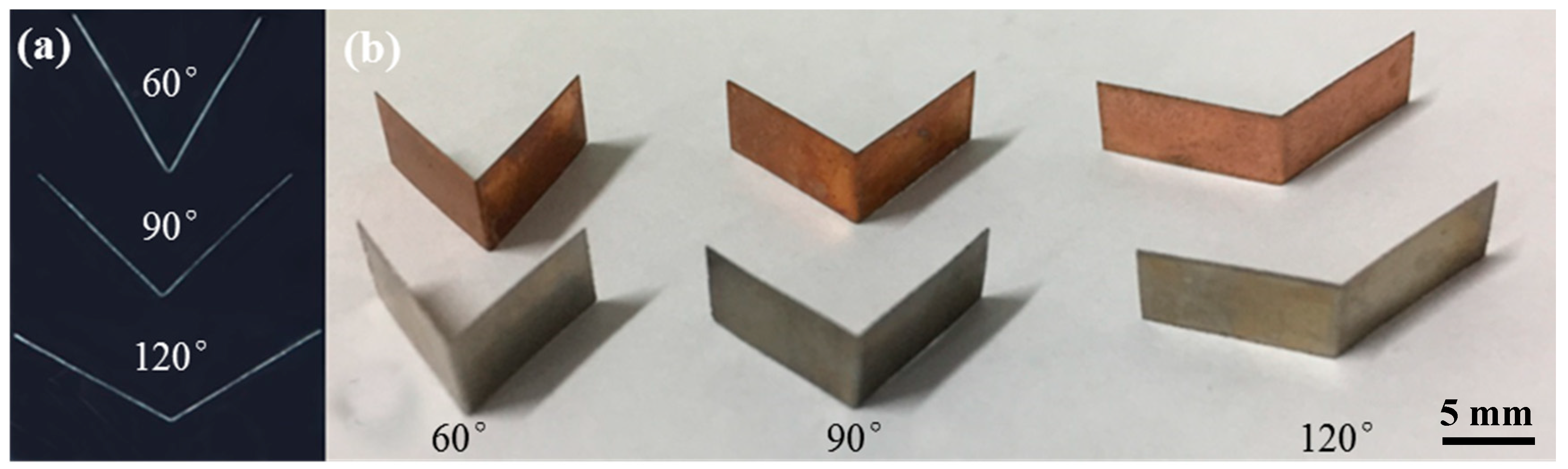
2.3. Experimental Procedure

The diagram of the V-bending process is shown in Figure 4. Square rubber with a thickness of 10 mm was put into the closed die. Then a clean clad foil was put in the center of the rubber, which can reduce the measurement error after springback. The punch was placed vertically into the die and touched lightly with the foil.
All the V-bending experiments were carried out on an electronic universal testing machine (INSTRON 5967, Instron LTD, Boston, MA, USA). The punches were pressed down at a velocity of 2 mm/min, and the fully bent specimens were obtained. Five specimens were tested under the same process parameter to verify the repeatability of experiments. Then the specimens were placed in different ways to repeat the experiment. The placement of Cu/Ni means that Cu layer is closed to the punch, and the placement of Ni/Cu means that Ni layer is closed to the punch. The profile of the bent specimens was obtained under a stereoscopic microscope and the thickness was obtained under a microscope (OLYMPUS DSX510, Olympus Corporation, Tokyo, Japan). The bending angle and foil thickness reduction after springback were measured by an electronic ruler in the microscope, and the effects of different experimental parameters on the quality of flexible die micro V-bending were analyzed. At least 5 points or specimens were used to measure the thickness or bending angle. The bent specimen are shown in Figure 5, where (a) shows the outline of the specimen bent by the punch die of 60°, 90°, and 120°, and (b) shows the specimen bent by the three kinds of punches. The Cu and Ni layers are not separated during the bending process because the strong interface of the Cu and Ni is formed during cold rolling and annealing. The Cu and Ni layers are constrained by the interfacial diffusion, mechanical occlusion, and metallurgical bonding.

3. Results and Discussion

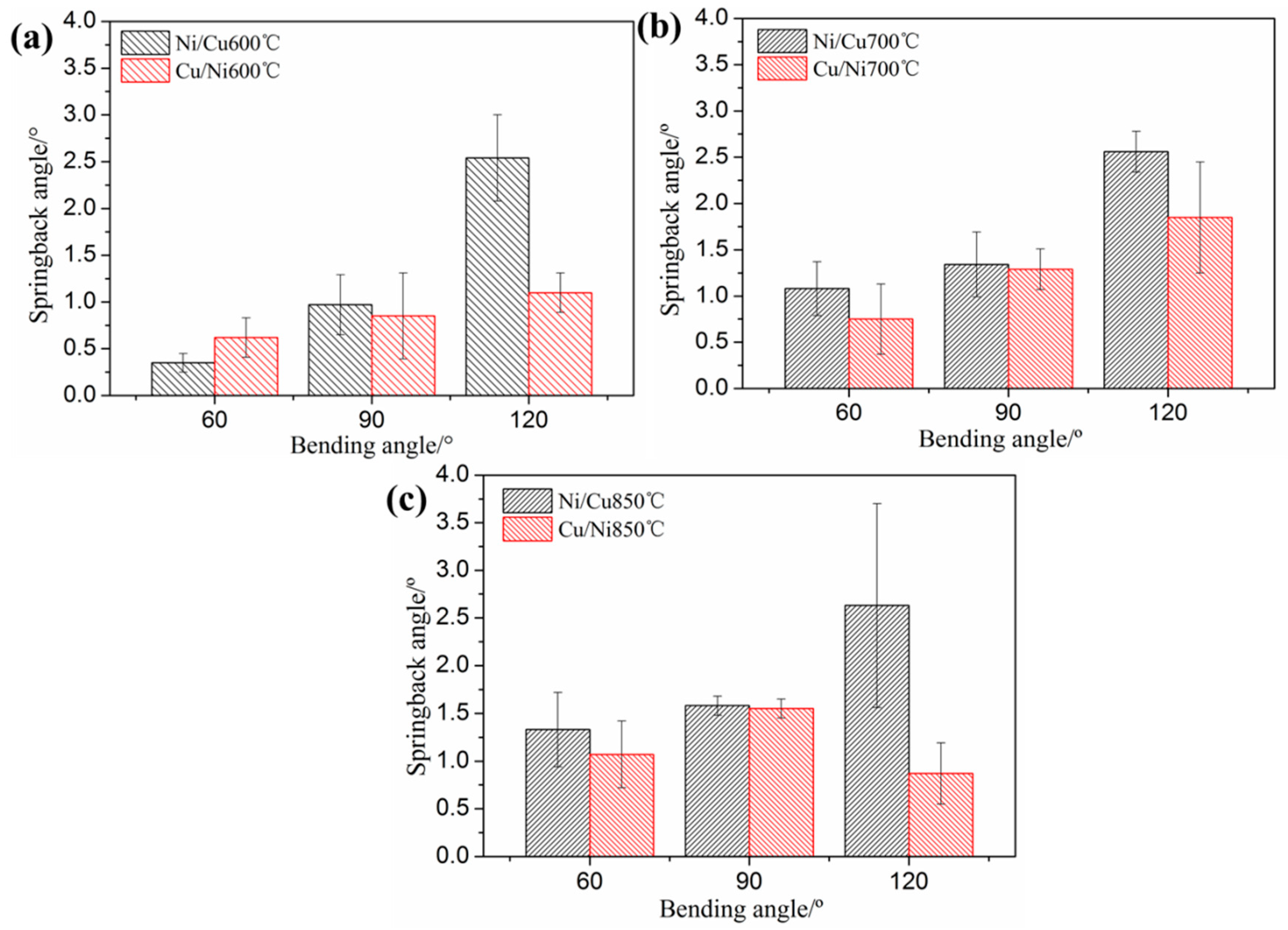
3.1. Springback Angle

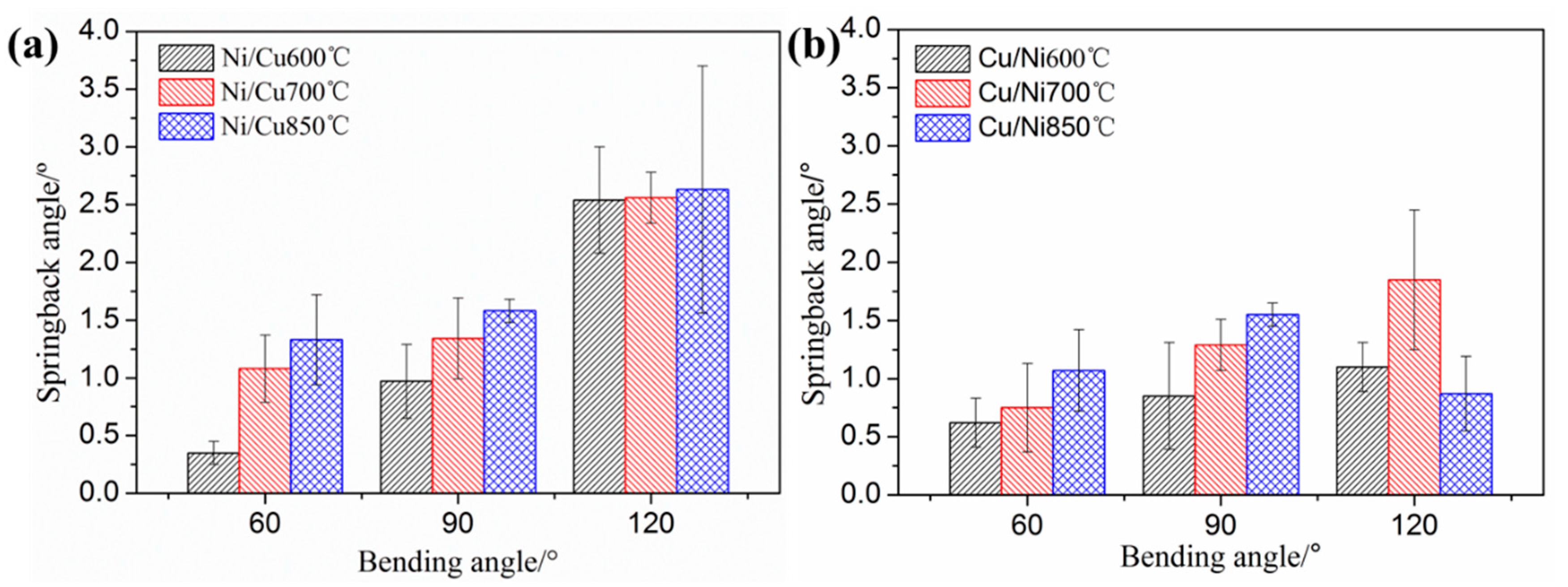
3.1.1. Effect of Bending Angle

The experimental results of Figure 6 show that the springback angle increases significantly when the bending angle decreases from 120° to 60° using the same annealed specimens and placement mode. This is because the bending deformation zone is divided into an elastic zone, elastoplastic zone and plastic zone [4], as shown in Figure 7. Under a certain relative bending radius, the length of the deformation zone and the springback accumulation increase with the increase of bending angle, which leads to an increase of springback. The diagram of the different bending angle is shown in Figure 8a. In order to analyze the characteristics of bending deformation more intuitively, a finite element model was established. The bending process was simulated by the dynamic display algorithm and displacement loading. Finally, the deformation degree at different bending angles can be seen by the equivalent strain distribution, as shown in Figure 8b. When the bending angle is 120° because the guide of the die is not long enough and the rubber has a certain elasticity, the punch is not stable during the downward pressing process and the springback angle fluctuates greatly. This is consistent with the results in the references [13,15,17].

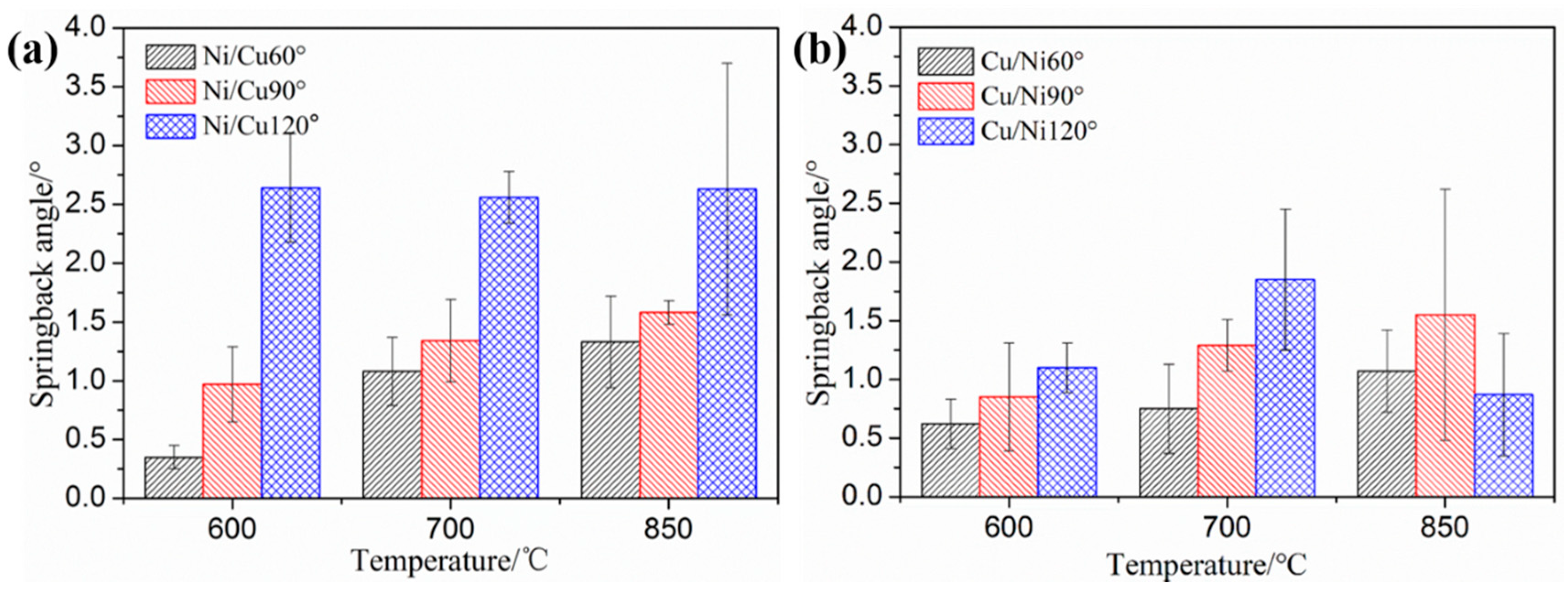
3.1.2. Effect of Annealing Temperature

The effect of the annealing temperature on the springback of Cu/Ni clad foils during flexible die micro V-bending process is shown in Figure 9. It is obvious that the springback increases with the annealing temperature. The annealing temperature determines the grain size. The higher the annealing temperature is, the larger the grain size is. On the one hand, the proportion of grain in the surface layer increases with the increase of grain size, and the strengthening effect is more obvious. On the other hand, inhomogeneous microstructure and complex boundaries make the deformation process difficult and then lead to an increase of springback in the case of the specimen with large grain size [17,22]. In the case of the specimen with large grain sizes, inhomogeneous microstructures and complex boundaries make the deformation process difficult and then lead to an increase of springback.

3.1.3. Effect of Placement Mode

From Figure 10, it can be observed that the springback angles for specimens under different annealing temperature and bending angles are larger when using Ni/Cu instead of Cu/Ni. Except for the specimen annealed at 600 °C and bent under 120° punch angle, the effect of placement on springback is different. Because of that, the elastic modulus of Cu is lower than that of Ni. When Ni is placed under Cu, the transverse stress of the transition layer after bending is compressive stress, which is slightly larger than that of the outer layer [24,25,26]. The stress neutral layer moves to the inner Ni layer and the bending moment increases. When using Ni/Cu, the transverse stress of the transition layer after bending is slightly less than that of the inner layer, and the stress neutral layer is still in the transition layer. The stress neutral layer is close to the geometric center of foil thickness and the bending moment decreases. The transverse stress distribution of S11 (normal stress along the length direction) is shown in Figure 11. The bending moment of Ni/Cu is larger than that of Cu/Ni thus the former springback is larger than that of the latter. Therefore, if the ratio of Ni to Cu increases, the position of the stress neutral layer will be more different and the springback angle will be larger when using Ni/Cu.

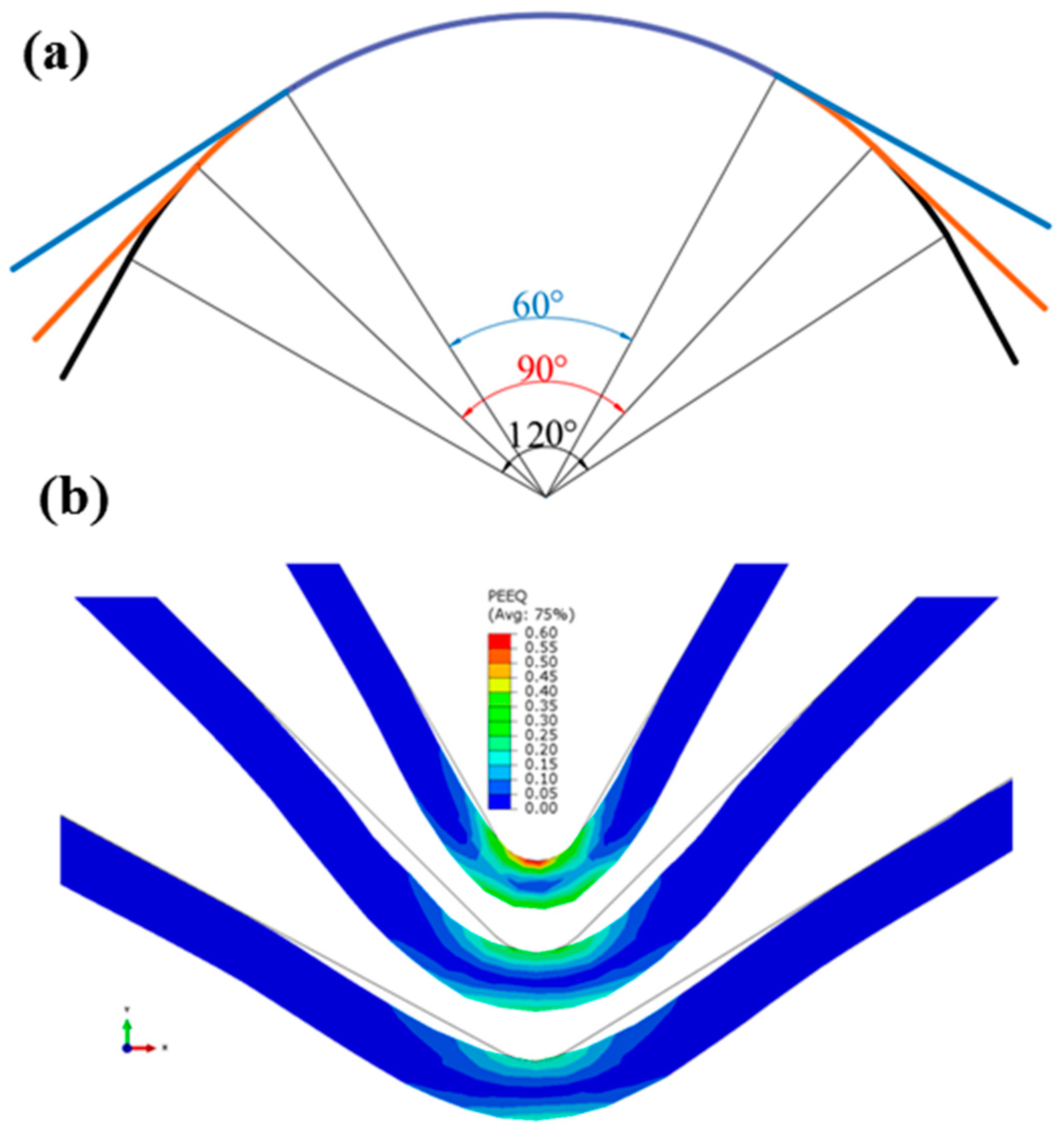
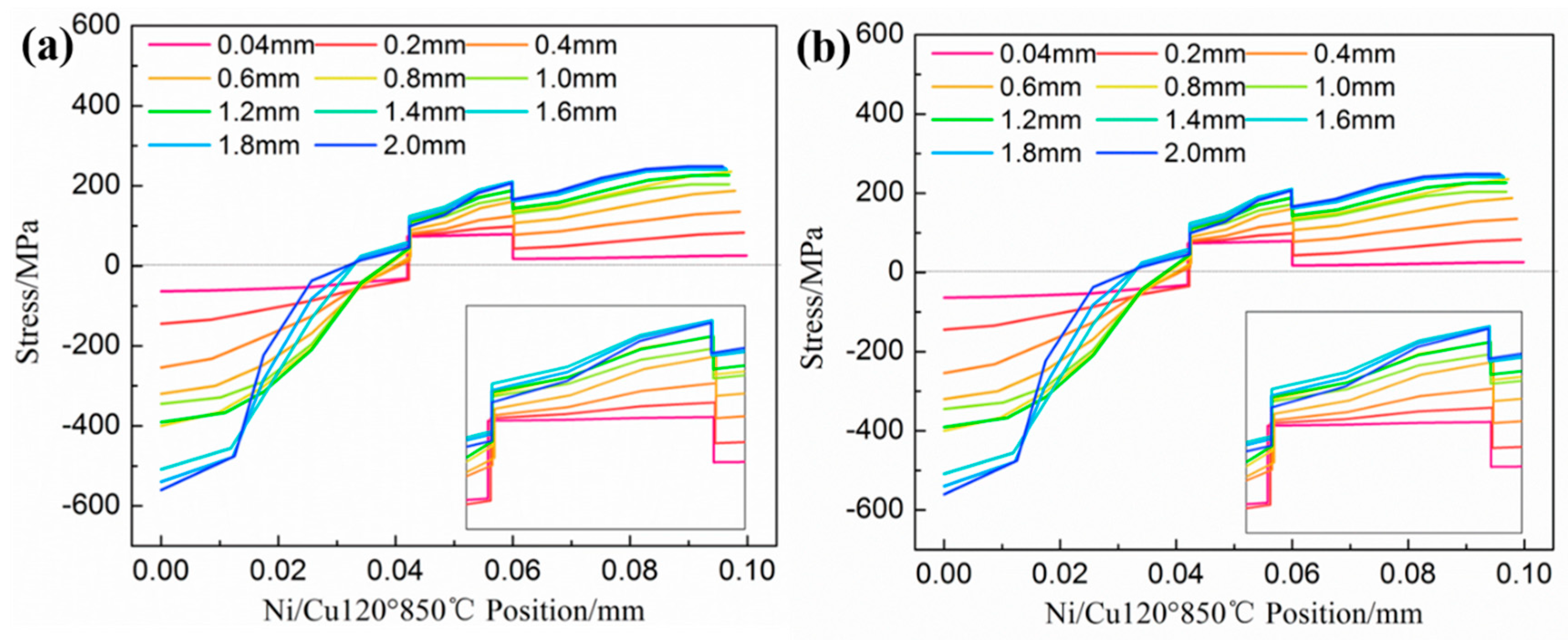
3.2. Analysis of Thickness Variation at Fillet

The thickness of the bent specimen was measured and it can be found from Table 2 that the thickness of the foil decreases when the annealing temperature is 850 °C and the placement is Ni/Cu. In order to analyze and observe the thickness deformation more accurately, the finite element simulation result was analyzed, which is shown in Figure 12. According to the results of experiments and simulations, thickness thinning increases with the increase of bending angle and deformation degree. It can be found from Table 2 and Figure 12 that the thickness (corner position or deformation region) of the clad foil decreases when the annealing temperature is 850 °C and the placement is Ni/Cu. The thickness thinning increases with the increase of the bending angle. However, the thickness of the Cu/Ni clad foil treated by the same annealing process increases with the increase of bending angle, as shown in Table 3. This is consistent with the air bending experimental results in reference [28]. When the softer layer is bent towards the punch, the clad foil may become thicker. This is because of that the transverse compressive stress is dominated when the Cu layer is located inside, which increases the thickness of the clad foil, as shown in Figure 13.

4. Conclusions

Cu/Ni clad foils with a thickness of 100 μm were selected as the experimental materials in the research. To investigate the influence of processing and material parameters on springback of micro V-bending of clad foils, the micro-bending experiments using flexible die were carried out and the characteristics of stress and strain were analyzed. The reasons for the variation of fillet thickness were analyzed. The following conclusive remarks can be drawn from the study:
(1) The bending angle has a significant effect on the bending process of clad foils, and the springback decreases with the increase of the bending angle. The reason is that the bending moment and elastic rebound are lower when using the small bending angle. The springback angle increases with the increase of annealing temperature. This is because of that the microstructure becomes inhomogeneous as the annealing temperature increases.
(2) The effect of placement on the bending process of clad foil is not significant. However, the springback of Ni/Cu is slightly higher than that of Cu/Ni. The difference in the bending moment results from the movement of the neutral layer. When using Ni/Cu, the neutral layer moves inward more significantly, resulting in a larger bending moment.
(3) The bending moment of the cross-section in the bending process is the superposition of the bending moment of the inner and outer sheet metals. The bending moments of each component are divided into the bending moment in the elastic zone and in the plastic zone. The curvature radius of the neutral layer of the clad foil after unloading is obtained by the relationship between bending moment and curvature variation.
(4) The thickness of the clad foil decreases along the fillet of the punch when using Cu/Ni. The thickness of the clad foil increases when using Ni/Cu. The reason is that the transverse compressive stress is dominated when the stronger Ni layer is inside.

Author Contributions

Conceptualization, C.W. and P.Z.; methodology, S.W. (Shuting Wang) and G.C.; software, S.W. (Shuting Wang) and S.W. (Shan Wang); validation, C.W.; formal analysis, G.C.; investigation, S.W. (Shan Wang) and S.W. (Shuting Wang); writing—original draft preparation, S.W. (Shan Wang); writing—review and editing, C.W. and P.Z.; supervision, C.W.; project administration, P.Z.

Funding

This study was financially supported by the National Natural Science Foundation of China (Grant No. 51875126 and Grant No. 51505101) and China Postdoctoral Science Foundation (Grant No. 2017T100238).

Conflicts of Interest

The authors declare no conflict of interest.

References

  1. Diehl, A.; Engel, U.; Merklein, M.; Geiger, M. Size effects in bending processes applied to metal foils. Prod. Eng. 2010, 4, 47–56. [Google Scholar] [CrossRef]
  2. He, P.; Yue, X.; Zhang, J.H. Hot pressing diffusion bonding of a titanium alloy to a stainless steel with an aluminum alloy interlayer. Mater. Sci. Eng. A 2008, 486, 171–176. [Google Scholar] [CrossRef]
  3. Manesh, D.H.; Shahabi, H.S. Effective parameters on bonding strength of roll bonded Al/St/Al multilayer. J. Alloy. Compd. 2009, 476, 292–299. [Google Scholar] [CrossRef]
  4. Li, H.Z.; Dong, X.H.; Wang, Q.; Shen, Y.; Diehl, A.; Hagenah, H.; Engel, U.; Merklein, M. Determination of material intrinsic length and strain gradient hardening in microbending process. Int. J. Solid. Struct. 2011, 48, 163–174. [Google Scholar] [Green Version]
  5. Chan, W.L.; Fu, M.W.; Yang, B. Experimental studies of the size effect affected microscale plastic deformation in micro upsetting process. Mater. Sci. Eng. A 2012, 534, 374–383. [Google Scholar] [CrossRef]
  6. Leu, D.K. Distinguishing micro-scale from macro-scale tensile flow stress of sheet metals in microforming. Mater. Des. 2015, 87, 773–779. [Google Scholar] [CrossRef]
  7. Zhao, B.; Wang, G.; Li, P. Study on constitutive relation of magnesium alloy foil based on size effect. J. Netshape Form. Eng. 2014, 6, 58–62. [Google Scholar]
  8. Farbaniec, L.; Couque, H.; Dirras, G. Size effects in micro-tensile testing of high purity polycrystalline nickel. Int. J. Eng. Sci. 2017, 119, 192–204. [Google Scholar] [CrossRef]
  9. Li, Y.; Wang, G.F.; Liu, S.Y.; Yang, J.L.; Yang, C.; Zhang, K.F. Drawability and size effects for micro-arrayed deep drawing of Ni-Co/GO nanocomposite foils. J. Mater. Process. Technol. 2017, 249, 221–225. [Google Scholar] [CrossRef]
  10. Zhang, Y.J.; Cheng, X.W.; Cai, H.N. Fabrication, characterization and tensile property of a novel Ti2Ni/TiNi micro-laminated composite. Mater. Des. 2016, 92, 486–493. [Google Scholar] [CrossRef]
  11. Idiart, M.I.; Deshpande, V.S.; Fleck, N.A.; Willis, J.R. Size effects in the bending of thin foils. Int. J. Eng. Sci. 2009, 47, 1251–1264. [Google Scholar] [CrossRef]
  12. Li, H.Z.; Dong, X.H.; Shen, Y.; Zhou, R.; Diehl, A.; Hagenah, H.; Merklein, M.; Cao, J. Analysis of microbending of CuZn37 brass foils based on strain gradient hardening models. J. Mater. Process. Technol. 2012, 212, 653–661. [Google Scholar] [CrossRef]
  13. Shan, D.B.; Wang, C.J.; Guo, B.; Wang, X.W. Effect of thickness and grain size on material behavior in micro-bending. Trans. Nonferr. Metal. Soc. 2009, 19, 507–510. [Google Scholar] [CrossRef]
  14. Wang, C.J.; Wang, X.W.; Guo, B.; Shan, D.B. Springback of C2680 brass foil in micro-bending test. Mater. Sci. Technol. 2009, 17, 5–7. [Google Scholar]
  15. Liu, J.G.; Fu, M.W.; Lu, J.; Chan, W.L. Influence of size effect on the springback of sheet metal foils in micro-bending. Comput. Mater. Sci. 2011, 50, 2604–2614. [Google Scholar] [CrossRef]
  16. Jiang, C.P. Initial grain size effect on mechanical properties and springback behavior of thin sheet metals with varying rolling reduction ratios. Int. J. Precis. Eng. Manuf. 2014, 15, 291–297. [Google Scholar] [CrossRef]
  17. Xu, Z.T.; Peng, L.F.; Bao, E.Z. Size effect affected springback in micro/meso scale bending process: Experiments and numerical modeling. J. Mater. Process. Technol. 2018, 252, 407–420. [Google Scholar] [CrossRef]
  18. Li, H.Z.; Dong, X.H.; Shen, Y.; Diehl, A.; Hagenahb, H.; Engel, U.; Merklein, M. Size effect on springback behavior due to plastic strain gradient hardening in microbending process of pure aluminum foils. Mater. Sci. Eng. A 2010, 527, 4497–4504. [Google Scholar] [CrossRef]
  19. Wang, Y.; Zhu, K.; Dong, P.; Wu, J.P.; Xu, Z.Y. Research on springback of micro-bending forming for ultra-thin sheet. Hot Work. Technol. 2016, 45, 107–109. [Google Scholar]
  20. Chen, L.; Chen, H.Q.; Guo, W.G.; Chen, G.J.; Wang, Q.Y. Experimental and simulation studies of springback in rubber forming using aluminium sheet straight flanging process. Mater. Des. 2014, 54, 354–360. [Google Scholar] [CrossRef]
  21. Bao, E.Z.; Peng, L.F.; Yi, P.Y. Size effect on springback of micro/meso scaled sheet in bending. J. Plast. Eng. 2016, 23, 58–63. [Google Scholar]
  22. Wang, X.; Qian, Q.; Shen, Z.B.; Li, J.W.; Zhang, H.F.; Liu, H.X. Numerical simulation of flexible micro-bending processes with consideration of grain structure. Comput. Mater. Sci. 2015, 110, 134–143. [Google Scholar] [CrossRef]
  23. Kim, H.; Nargundkar, N.; Altan, T. Prediction of bend allowance and springback in air bending. J. Manuf. Sci. Eng. 2007, 129, 342–351. [Google Scholar] [CrossRef]
  24. Shayan, M.; Mohammadpo, M.; Massoud, M.; Ding, H. Springback analysis of two-layer strips in clad cold bimetal bending. Trans. Indian Inst. Metals 2014, 67, 851–859. [Google Scholar] [CrossRef]
  25. Yilamu, K.; Hino, R.; Hamasaki, H.; Yoshida, F. Air bending and springback of stainless steel clad aluminum sheet. J. Mater. Process. Technol. 2010, 210, 272–278. [Google Scholar] [CrossRef]
  26. Parsa, M.H.; Mohammadi, S.V.; Mohseni, E. Thickness change and springback of cold roll bonded Al/Cu clad sheets in air bending process. Proc. Inst. Mech. Eng. Part B J. Eng. Manuf. 2015, 231, 675–689. [Google Scholar] [CrossRef]
  27. Gau, J.T.; Principe, C.; Yu, M. Springback behavior of brass in micro sheet forming. J. Mater. Process. Technol. 2007, 191, 7–10. [Google Scholar] [CrossRef]
  28. Zhang, D.J.; Cui, Z.S.; Chen, Z.Y.; Ruan, X.Y. An analytical model for predicting sheet springback after V-bending. J. Zhejiang Univ. Sci. A 2007, 8, 237–244. [Google Scholar] [CrossRef]
  29. Dirikolu, M.H.; Akdemir, E. Computer aided modelling of flexible forming process. J. Mater. Process. Technol. 2004, 148, 376–381. [Google Scholar] [CrossRef]
Figure 1. Cross-section along the rolling direction of the specimen.
Metals 09 00892 g001
Figure 2. Micro-structures of billets along a rolling direction at different annealing temperatures (a) 600 °C, (b) 700 °C, and (c) 850 °C.
Metals 09 00892 g002
Figure 3. (a) Experimental platform, (b) punches, (c) die cavity, and (d) punch angles.
Metals 09 00892 g003
Figure 4. Diagram of V-bending process.
Metals 09 00892 g004
Figure 5. (a) Profiles and (b) view of bent specimens.
Metals 09 00892 g005
Figure 6. Springback angle for specimens under different bending angles (a) Ni/Cu and (b) Cu/Ni.
Metals 09 00892 g006
Figure 7. Deformation zone in bending.
Metals 09 00892 g007
Figure 8. (a) Diagram of bent specimens under different bending angles and (b) equivalent strain distribution.
Metals 09 00892 g008
Figure 9. Springback angle for specimen under different annealing temperature (a) Ni/Cu and (b) Cu/Ni.
Metals 09 00892 g009
Figure 10. Springback angle for specimens under different placement modes (a) annealing at 600 °C, (b) annealing at 700 °C, and (c) annealing at 850 °C.
Metals 09 00892 g010
Figure 11. Transverse stress distribution under punch angle 120° and annealing temperature 850 °C (a) Ni/Cu, and (b) Cu/Ni.
Metals 09 00892 g011
Figure 12. Equivalent strain distribution of finite element model.
Metals 09 00892 g012
Figure 13. Equivalent strain distribution in bending by the finite element model.
Metals 09 00892 g013
Table 1. Grain size and thickness of the component layer.
Annealing Temperature (°C)600700850
Grain size of Cu layer (μm)39.7356.4162.74
Grain size of Ni layer (μm)15.5217.8922.91
Thickness of Cu layer (μm)49.6746.2844.04
Thickness of the interface layer (μm)7.9012.9416.37
Thickness of Ni layer (μm)42.4340.7839.59
Table 2. The thickness of round corner after springback for Ni/Cu annealed under 850 °C.
Bending Angle (°)6090120
Experiment-thickness (μm)96.3288.7283.22
Simulation-thickness (μm)95.8792.8692.81
Table 3. The thickness of round corner after springback for Cu/Ni with a bending angle of 60°.
Annealing Temperature (°C)600700850
Experiment-thickness (μm)104.49109.20112.85
Simulation-thickness (μm)97.0697.2097.23

