Article

A Macroscopic Strength Criterion for Isotropic Metals Based on the Concept of Fracture Plane

1
Jiangsu Key Laboratory of Advanced Food Manufacturing Equipment and Technology, Jiangnan University, Wuxi 214122, China
2
State Key Laboratory of Mechanics and Control of Mechanical Structures, Nanjing University of Aeronautics and Astronautics, Nanjing 210016, China
3
School of Mechanical Engineering, Jiangnan University, Wuxi 214122, China
*
Authors to whom correspondence should be addressed.
Metals 2019, 9(6), 634; https://doi.org/10.3390/met9060634
Submission received: 16 May 2019 / Revised: 29 May 2019 / Accepted: 30 May 2019 / Published: 31 May 2019
(This article belongs to the Special Issue Failure Mechanisms in Alloys)

Abstract

:
Although the linear Mohr–Coulomb criterion is frequently applied to predict the failure of brittle materials such as cast iron, it can be used for ductile metals too. However, the criterion has some significant deficiencies which limit its predictive ability. In the present study, the underlying failure hypotheses of the linear Mohr–Coulomb criterion were thoroughly discussed. Based on Mohr’s physically meaningful concept of fracture plane, a macroscopic strength criterion was developed to explain the failure mechanism of isotropic metals. The failure function was expressed as a polynomial expansion in terms of the stresses acting on the fracture plane, and the quadratic approximation was employed to describe the non-linear behavior of the failure envelope. With an in-depth understanding of Mohr’s fracture plane concept, the failure angle was regarded as a generalized strength parameter in addition to the failure stress (i.e., the conventional basic strength). The undetermined coefficients of the non-linear failure function were calibrated by the strength parameters obtained from the common uniaxial tension and compression tests. Theoretical and experimental assessment for different types of isotropic metals validated the effectiveness of the proposed criterion in predicting material failure.

1. Introduction

A considerable number of failure criteria for isotropic materials have been developed since the establishment of classical mechanics [1]. Among all the proposed criteria, the Mises criterion is extensively used for ductile metals. However, it cannot be applied to metallic materials which have the strength difference effect (i.e., the uniaxial tensile strength T is not equal to the uniaxial compressive strength C). The linear Mohr–Coulomb criterion is very popular due to its simplicity and general applicability. Although the criterion is frequently used to predict the failure of brittle materials such as cast iron, it can also be applied to very ductile metals [2]. In the special case of ductile materials without the strength difference effect, the criterion degenerates into the maximum shear stress criterion (also known as the Tresca criterion), which is widely-used for conventional ductile metals.
Both Mohr and Coulomb have made an important contribution to the linear Mohr–Coulomb criterion. Mohr proposed that the fracture limit of a material is determined by the stress components σn and τn on the fracture plane [3] (see Figure 1). Coulomb’s assumption is based on a linear failure envelope to determine the critical combination of σn and τn [4], which gives:
τ n + μ σ n = c .
Under uniaxial loading, material failure occurs when Mohr’s circle for uniaxial tension or compression is just tangent to the envelope (see Figure 2). Hence the two material-specific parameters μ and c in Equation (1) can be calibrated by the uniaxial tensile strength T and the uniaxial compressive strength C.
In the principal stress space (σ1, σ2, σ3), the linear Mohr–Coulomb criterion can be expressed in an extremely simple form of
σ 1 T σ 3 C = 1 ,
where σ1 and σ3 are the maximum and minimum principal stresses respectively.
Although the classic Mohr–Coulomb criterion has been extensively used in research and engineering [5], it has several significant deficiencies which limit its predictive ability:
Firstly, the fracture angles predicted by the linear Mohr–Coulomb criterion do not always agree with the experimental observations. For example, experimental results show that typical brittle metals such as cast iron with T/C = 1/4 fail in tension on the plane parallel to the action plane of the applied load, i.e., the tensile fracture angle θT = 90.0° (see Figure 3a). However, the criterion predicts the tensile fracture angle θT = 63.4°. Under uniaxial compression the fracture angle of cast iron should be approximately 37.0° (see Figure 3b), yet the predicted angle θC = 26.6°. Moreover, the summation of the tensile and compressive failure angles is exactly 90° for all types of isotropic metals according to the prediction of the linear Mohr–Coulomb criterion. This conclusion does not correlate with the measured data of cast iron (θT = 90.0°, θC = 37.0° (see Figure 3)) and metallic glass (θT = 50.7°, θC = 43.0° (see Figure 4)).
Secondly, the linear Mohr–Coulomb criterion cannot explain the pure shear fracture behavior of cast iron with T/C = 1/4. The predicted pure shear strength is S = 0.8T with the fracture angle θS = 26.6°, while the measured strength is S = T with the fracture angle θS = 45° (see Figure 5).
Thirdly, the criterion asserts that the equi-triaxial tensile strength Ttri is much stronger than the uniaxial tensile strength T for brittle materials. This unphysical behavior has no supporting evidence [9].
Lastly, Christensen [9] gave a simple example which shows the inaccuracy of the linear Mohr–Coulomb criterion. Take a 3D compressive stress state given by σ1 = σ2 = −σ, σ3 = −2σ. The criterion predicts that isotropic materials with T/C ≤ 1/2 can sustain unlimited compressive stresses, which is completely unrealistic.
The above problems reveal the inappropriateness of the linear Mohr–Coulomb criterion for isotropic metals in certain cases. Much effort has been made to modify the criterion. Paul suggested combining the linear Mohr–Coulomb criterion with the maximum normal stress criterion [10]. Yu proposed the twin-shear strength theory to replace the single shear strength theory (i.e., the linear Mohr–Coulomb criterion) [1]. Bigoni and Piccolroaz generalized the criterion using the invariants of the stress tensor [11]. However, Mohr’s physically meaningful concept of fracture plane was ignored by these researchers, thus the aforementioned contradictions between the predictions and experimental results cannot be fundamentally solved.
It is worth noting that the concept of critical plane in fatigue analysis is similar to the aforementioned concept of fracture plane in static failure analysis. There are also a lot of critical plane-based fatigue failure criteria for metallic materials [12]. Brown and Miller [13] assumed the critical plane is the plane with maximum shear strain, and proposed that fatigue failure depends on the combination of the normal and shear strains acting on the critical plane. Glinka et al. [14] applied the normal and shear strain energy densities on the critical plane instead of the strains, formulating a strain energy density criterion based on the critical plane approach. The approach has been recently extended to the nanoscale by Gallo et al. [15,16].
In the present study, the linear Mohr–Coulomb criterion is modified based on an in-depth understanding of Mohr’s concept of fracture plane. Not only the uniaxial strengths T and C but also the failure angles θT and θC are used as basic strength parameters to calibrate the unknown coefficients of the non-linear failure function. The macroscopic strength criterion shows good agreement with the experimental data of different types of isotropic metals, and has a better predictive ability compared with the linear Mohr–Coulomb criterion.

2. Discussion of the Linear Mohr–Coulomb Criterion

Since the proposed macroscopic strength criterion is based on Mohr’s fracture plane concept, the failure hypotheses of the linear Mohr–Coulomb criterion are re-examined at first.
Material failure often originates from a specific plane [17]. Mohr proposed that the fracture limit of a material is determined by the stress components σn and τn on the fracture plane (see Figure 1). As shown in Figure 6a,b, both the plane separation driven by the normal tensile stress σn and the plane sliding driven by the shear stress τn can result in macroscopic material failure. These two stress components are correlated with the two main failure mechanisms in solids: cleavage and slip, respectively [18]. The normal compressive stress increases the difficulty of shearing along the plane, thus suppressing material failure (see Figure 6c). From the microscopic point of view, materials contain micro defects to varying degrees. The tensile normal stress is expected to open these flaws and cause them to grow, whereas under the normal compressive stress the flaws tend to have their opposite sides pressed together [6]. The shear stress drives the dislocation movement of a large number of planes of atoms [19], leading to macroscopic material distortion. Hence it can be concluded that the normal tensile stress and the shear stress promote material failure, while the normal compressive stress inhibits failure.
The undetermined coefficients of failure criteria are usually calibrated by the maximum sustainable stresses under certain special loading conditions. The absolute value of the maximum sustainable stress is commonly referred to as “basic strength”, which is calculated by dividing the applied load by the area of its own action plane [3]. The linear Mohr–Coulomb criterion takes the uniaxial tensile strength T and the uniaxial compressive strength C as the basic strengths.
It can be inferred from Mohr’s fracture hypothesis that the maximum sustainable stresses actually should be the stress components acting on the fracture plane. Nevertheless, the action plane of the applied load may not be parallel to the fracture plane. For example, as observed in the uniaxial tension test, the fracture of metallic glass occurs on an inclined plane of θT = 50.7° (see Figure 4a). The uniaxial tensile strength T is defined as the value of the tensile failure stress (i.e., the uniaxial tensile failure load divided by the area of its action plane). However, it is the normal tensile stress component σ n = T 2 ( 1 cos 2 θ T ) and the shear stress component τ n = T 2 sin 2 θ T on the fracture plane that lead to material failure. Similarly, the fracture of metallic glass occurs on an inclined plane of θC = 43.0° under the uniaxial compressive loading (see Figure 4b). The compressive fracture behavior of metallic glass is actually determined by the normal compressive stress component σ n = C 2 ( cos 2 θ C 1 ) and the shear stress component τ n = C 2 sin 2 θ C on the fracture plane. Therefore, it is insufficient to characterize Mohr’s concept solely by the conventional basic strength. Only by both the failure stress (i.e., the basic strength) and the failure angle, can the maximum sustainable stresses on the fracture plane be determined. It indicates that in strict accordance with Mohr’s fracture plane concept, both the conventional strength value and the failure angle should be measured in a uniaxial test [20].
Although Coulomb’s linear failure envelope is able to distinguish the different effects of the normal tensile and compressive stresses on material failure, the experimentally-determined envelopes often exhibit non-linear behavior [21]. Thus, the linear strength response is regarded as a major limitation of the classic Mohr–Coulomb criterion [19], and a non-linear form of the envelope is supposed to fit the experimental data better. Nevertheless, besides the common uniaxial tension and compression tests, additional experiments are usually required in order to determine the unknown parameters of the non-linear failure function. For example, the pure torsion test is needed in our previous research work [22]; equi-biaxial tension, equi-biaxial compression or other combined stress state tests are needed in the criterion proposed by Hu and Wang [23].

3. Formulation of the Strength Criterion

In this section, we propose a feasible method to modify the linear Mohr–Coulomb criterion. Only two common types of tests (i.e., the uniaxial tension and compression tests) are required in order to use the present criterion.

3.1. Mathematical Expression of the Failure Function

The mathematical expression of the failure function is constructed using the general approach put forward by us [22,24], which is briefly described below:
According to Mohr’s fracture hypothesis, the failure function, F, should be the function of the stress components (σn, τn) on the fracture plane. Material failure occurs when F(σn, τn) reaches the failure index 1. Expanding F into a polynomial in terms of (σn, τn), we get:
F ( σ n , τ n ) = α σ n + β σ n 2 + γ σ n τ n + λ τ n + ω τ n 2 + = 1 ,
where … represents the terms of cubic and higher orders.
The quadratic form is frequently chosen as the non-linear failure function for isotropic materials due to its relatively good curve-fitting results [7,22,25,26]. In addition, much more experimental data are required to determine the unknown coefficients if cubic or higher order approximations are employed. Therefore, in the present study the failure function F is truncated at the quadratic order, i.e.,
F ( σ n , τ n ) = α σ n + β σ n 2 + γ σ n τ n + λ τ n + ω τ n 2 = 1 .
Whether the shear stress component is positive or negative, it always makes an identical contribution to material failure. Hence the linear terms of the shear stress component, namely σnτn and τn, shall be vanished in Equation (4), leaving
F ( σ n , τ n ) = α σ n + β σ n 2 + ω τ n 2 = 1 .
The normal tensile stress on the fracture plane promotes material failure, while the normal compressive stress inhibits failure. It has been demonstrated that the normal tensile stress has much more pronounced effect on material failure than the normal compressive stress [7]. Therefore, unlike the linear Mohr–Coulomb criterion, the failure behaviors under the normal tensile and compressive stresses are treated separately in the present theory:
F ( σ n , τ n ) = α C σ n + β C σ n 2 + ω τ n 2 = 1   for   σ n 0 ,
F ( σ n , τ n ) = α T σ n + β T σ n 2 + ω τ n 2 = 1   for   σ n > 0 ,
where α C , β C , α T , β T and ω are the undetermined parameters.

3.2. Failure Function for σn ≤ 0

We first consider the equi-triaxial compressive strength condition σ1 = σ2 = σ3 = −Ctri. The stress components on any section plane are given by (σn = −Ctri, τn = 0) under hydrostatic compression. Substituting (σn = −Ctri, τn = 0) into Equation (6), we get:
β C = 1 C t r i 2 + α C C t r i .
Experiments have shown that isotropic materials can be loaded to very high values of hydrostatic pressure without failure [19], i.e., Ctri→∞. Hence βC can be approximated by
β C = 0 .
Additional information can be obtained from the uniaxial compression test. As is discussed in Section 2, both the uniaxial compressive strength C and the corresponding failure angle θC are used as generalized strength parameters in the present theory. As shown in Figure 7, the stress components on the potential failure plane under uniaxial compression are given by:
σ n = C 2 ( cos 2 θ 1 ) ,
τ n = C 2 sin 2 θ .
Substituting Equations (9)–(11) into the failure function F in Equation (6), we get:
F ( θ ) = α C C 2 ( cos 2 θ 1 ) + ω ( C 2 sin 2 θ ) 2 .
The failure function F reaches the maximum value 1 when failure occurs on the action plane oriented at θ = θC:
F ( θ C ) = α C C 2 ( cos 2 θ C 1 ) + ω ( C 2 sin 2 θ C ) 2 = 1 ,
d F d θ | θ = θ C = ( α C C + ω C 2 cos 2 θ C ) sin 2 θ C = 0 .
As shown in Figure 7, there is no stress component on the plane oriented at θ = 0°, and only the normal compressive stress which inhibits material failure acts on the plane oriented at θ = 90°. Therefore, sin2θC≠ 0 always holds. Solving Equation (14), we get
α C + C cos 2 θ C ω = 0 .
The coefficients α C and ω can be determined by solving Equations (13) and (15) together:
α C = 4 cos 2 θ C C ( cos 2 θ C 1 ) 2 ,
ω = 4 C 2 ( cos 2 θ C 1 ) 2 .

3.3. Failure Function for σn > 0

The uniaxial tensile strength T and the corresponding failure angle θT are used to calibrate the undetermined parameters of the failure function for σn > 0. As shown in Figure 7, the stress components on the potential failure plane under uniaxial tension are given by:
σ n = T 2 ( 1 cos 2 θ ) ,
τ n = T 2 sin 2 θ .
Substituting Equations (18) and (19) into the failure function F in Equation (7), we obtain:
F ( θ ) = α T T 2 ( 1 cos 2 θ ) + β T [ T 2 ( 1 cos 2 θ ) ] 2 + ω ( T 2 sin 2 θ ) 2 .
The failure function F reaches the maximum value 1 when failure occurs on the action plane oriented at θ = θT:
F ( θ T ) = α T T 2 ( 1 cos 2 θ T ) + β T [ T 2 ( 1 cos 2 θ T ) ] 2 + ω ( T 2 sin 2 θ T ) 2 = 1 ,
d F d θ | θ = θ T = [ α T + β T T ( 1 cos 2 θ T ) + ω T cos 2 θ T ] T sin 2 θ T = 0 .
As shown in Figure 7, since there is no stress component on the plane oriented at θ = 0°, θT ≠ 0° always holds. If θT ≠ 90°, from Equation (22) we obtain:
α T + β T T ( 1 cos 2 θ T ) + ω T cos 2 θ T = 0 .
The coefficients α T and β T can be determined by solving Equations (17), (21), and (23) together:
α T = 4 T ( 1 cos 2 θ T ) 4 T C 2 ( 1 cos 2 θ C ) 2 ,
β T = 4 C 2 ( 1 cos 2 θ C ) 2 4 T 2 ( 1 cos 2 θ T ) 2 .
If θT = 90°, from Equation (21) we get:
α T T + β T T 2 = 1 .
However, Equation (22) is naturally satisfied if θT = 90°. Therefore, in this case the uniaxial tension test actually provides only one equation for determination of the two unknown coefficients α T and β T . No supplementary information is available from the uniaxial tension test to establish another equation. Since extra experiments may be difficult, time-consuming, and expensive, an alternative method is proposed to construct an additional equation.
The failure envelope is commonly expected to be as smooth as possible considering the implementation of numerical methods [19]. The left derivative of the failure envelope at σn = 0 can be derived from Equation (6):
d τ n d σ n | σ n = 0 = α C 2 ω τ n | σ n = 0 ,
and the right derivative of the failure envelope at σn = 0 can be derived from Equation (7):
d τ n d σ n | σ n = 0 + = α T 2 ω τ n | σ n = 0 .
Applying the smooth condition, we get:
α C = α T .
The coefficients α T and β T can be determined by solving Equations (17), (26) and (29) together:
α T = 4 cos 2 θ C C ( cos 2 θ C 1 ) 2 ,
β T = 1 T 2 4 cos 2 θ C T C ( cos 2 θ C 1 ) 2 .

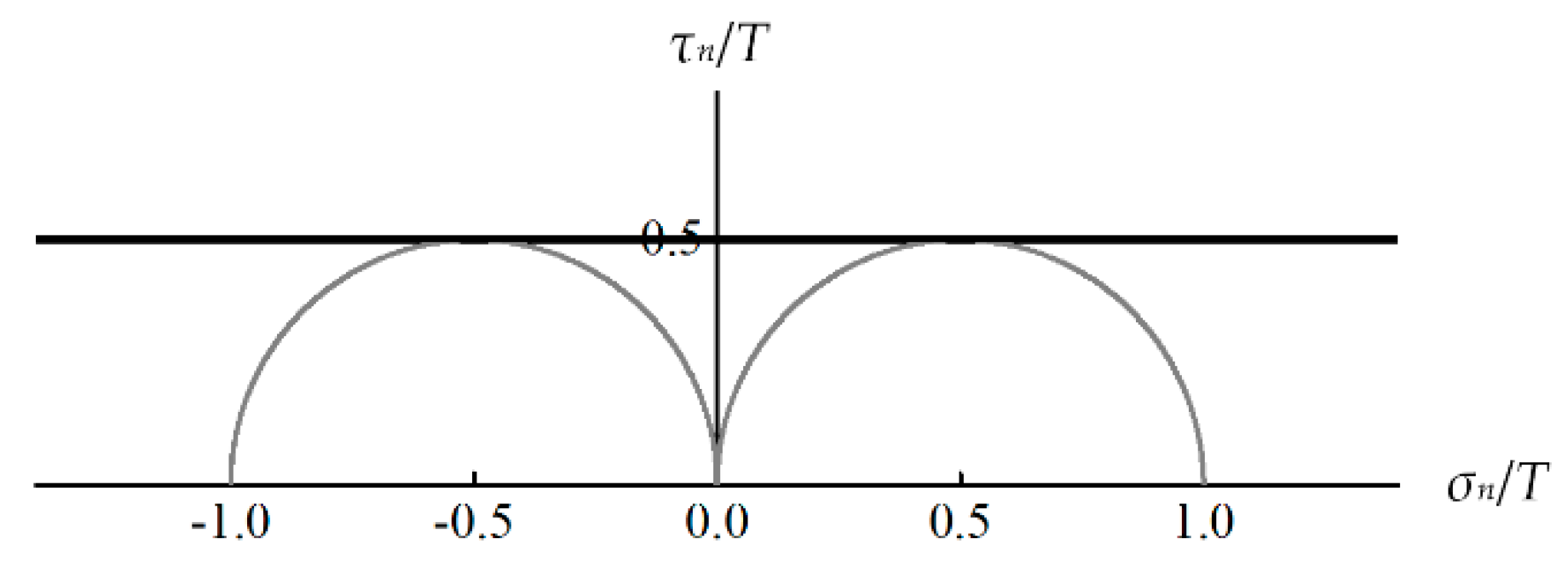
3.4. Function of the Failure Envelope

To sum up, the function of the failure envelope is expressed as
F ( σ n , τ n ) = { α C σ n + ω τ n 2 = 1 for   σ n 0 α T σ n + β T σ n 2 + ω τ n 2 = 1 for   σ n > 0 ,
where
α C = 4 cos 2 θ C C ( cos 2 θ C 1 ) 2 ,
ω = 4 C 2 ( cos 2 θ C 1 ) 2 ,
α T = { 4 T ( 1 cos 2 θ T ) 4 T C 2 ( 1 cos 2 θ C ) 2 if   θ T 90 4 cos 2 θ C C ( cos 2 θ C 1 ) 2 if   θ T = 90 ,
β T = { 4 C 2 ( 1 cos 2 θ C ) 2 4 T 2 ( 1 cos 2 θ T ) 2 if   θ T 90 1 T 2 4 cos 2 θ C T C ( cos 2 θ C 1 ) 2 if   θ T = 90 .
The terms α C σ n , ω τ n 2 , and α T σ n + β T σ n 2 in Equation (32) represent the contribution of the normal compressive stress, the normal tensile stress, and the shear stress to material failure respectively.

4. Theoretical and Experimental Evaluation

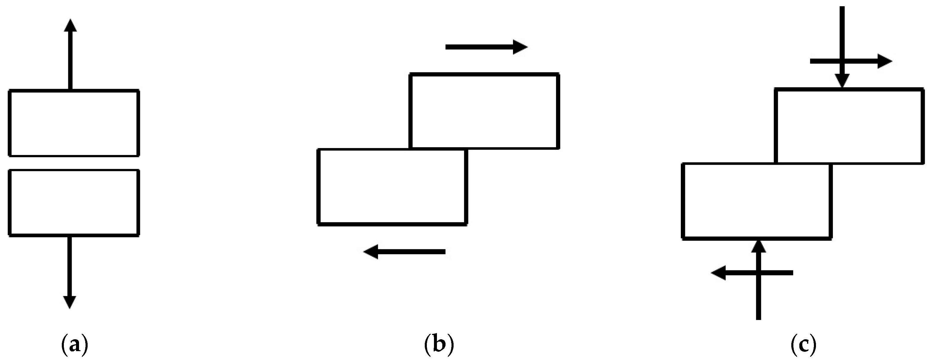
4.1. Failure Modes under Uniaxial Tension and Compression

The uniaxial tension and compression tests were conducted on three different types of isotropic metals, namely the ductile metallic material, metallic glass, and brittle cast iron. The specimens were elaborately designed to avoid either material damage near the clamping end under uniaxial tension, or buckling and end effects under uniaxial compression. The tensile and compressive specimens were tested at a constant strain rate using the universal testing machine, and the failure strengths and failure angles were measured carefully. Further details about the experiments can be found in [6,7,27]. The strength parameters of the isotropic metals are listed in Table 1, while the failure angles θT and θC predicted by the linear Mohr–Coulomb criterion are listed in Table 2. Comparison between Table 1 and Table 2 shows that the predicted failure angles of the three tested materials are not entirely consistent with the measured values, especially in the case of brittle cast iron.
As shown in Table 3, since the normal compressive stress σn suppresses material failure under uniaxial compression, αCσn 0 always holds. Hence all types of isotropic metals fail in the shear mode under uniaxial compression. Under uniaxial tension, because both the normal tensile stress and the shear stress promote material failure, the terms related to σn and τn are always non-negative (see Table 4). With the increase of material brittleness, the failure mode gradually transfers from shear to tension under the uniaxial tensile loading.

4.2. Ductile Metallic Material

For conventional ductile metallic materials such as Al-alloy, Ti-alloy and steels, material failure is usually specified by yielding. Therefore, the measured strength and failure plane actually should be the yield strength and slip plane of ductile metals. Nearly no difference between the tensile and compressive strengths can be observed for these materials [7]. In the ductile limiting case T = C, θT = θC = 45°, both the present criterion and the linear Mohr–Coulomb criterion degenerate into the form of
τ n = σ 1 σ 3 2 = T 2 ,
see Figure 8. Equation (37) is the exact form of the Tresca criterion, which is suitable for typical ductile materials.

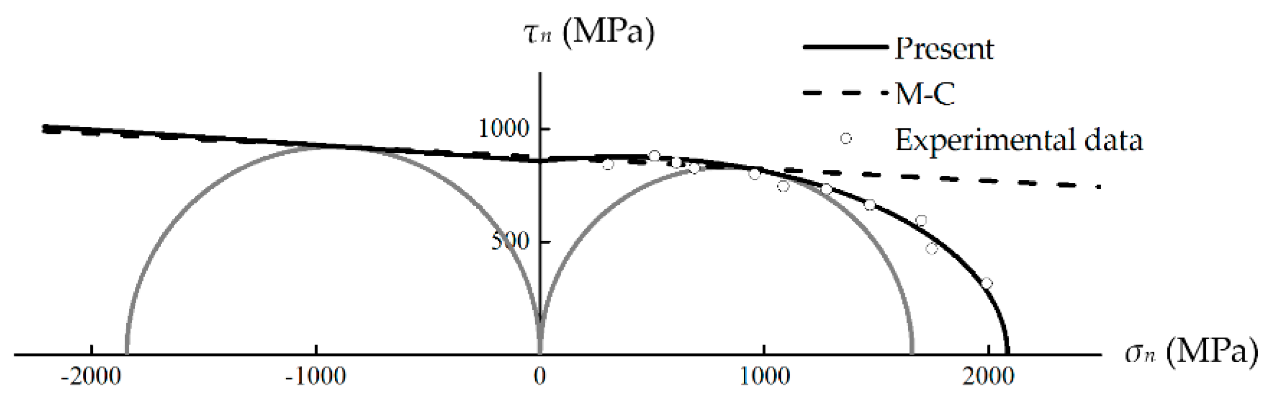
4.3. Metallic Glass with Moderate Ductility

Metallic glass is a kind of high-strength isotropic material, yet with relatively lower ductility than conventional ductile metallic materials. The linear Mohr–Coulomb criterion has been applied to describe the fracture behavior of metallic glass due to its ability to characterize the TC strength asymmetry [28]. However, as shown in Figure 9, obviously the present criterion fits the experimental data better than the linear Mohr–Coulomb criterion in the high normal tensile stress range. In the normal compressive stress range, the envelope predicted by the present criterion is similar to that predicted by the linear Mohr–Coulomb criterion. It is worth noting that the proposed failure envelope is non-smooth at the transition location σn = 0. This is because the proposed function of the failure envelope, Equation (32), is only an acceptable, but not perfect approximation to the “true” or “ideal” failure function.

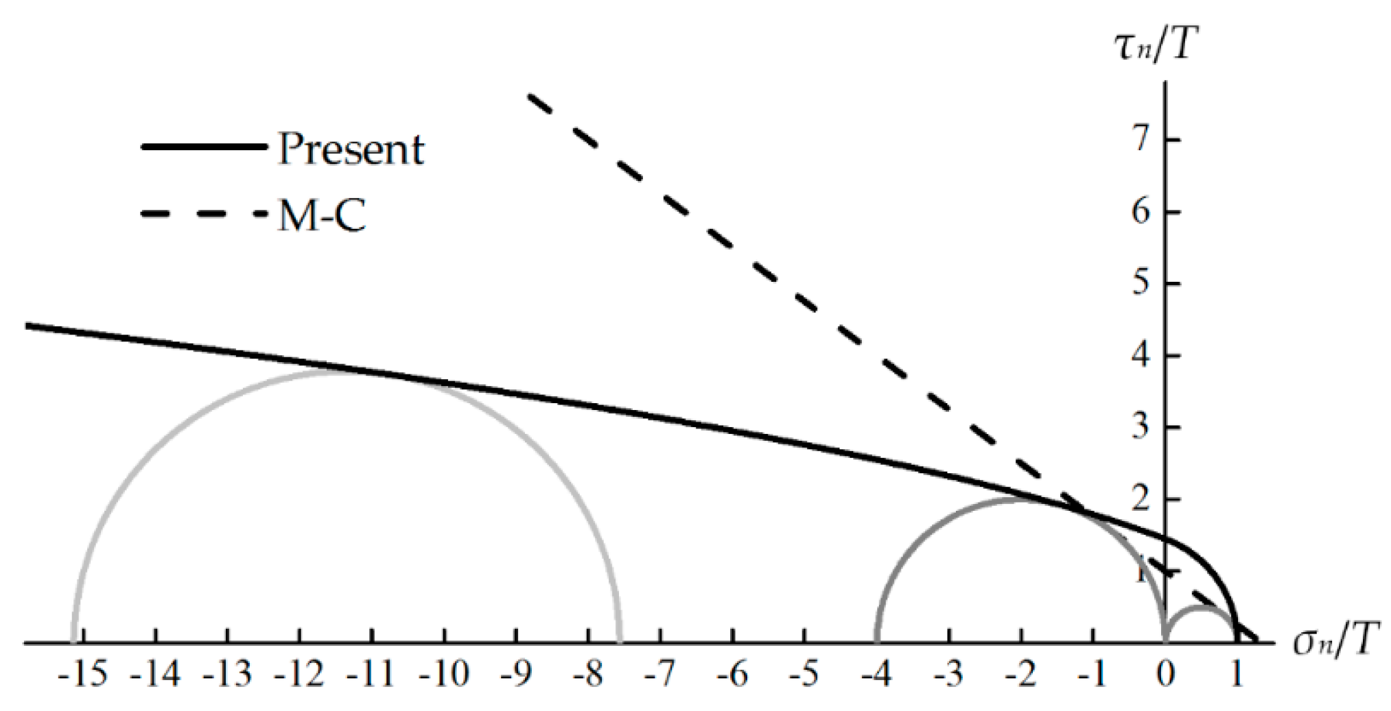
4.4. Brittle Cast Iron

Cast iron is a typical brittle metal with the measured fracture angles θT = 90.0° and θC = 37.0° [6]. The failure envelopes predicted by the present criterion and the linear Mohr–Coulomb criterion are plotted in Figure 10, and Mohr’s circles for uniaxial tension, uniaxial compression and pure shear are also depicted. The envelope given by the present criterion agrees with the experimental observation that fracture occurs on the plane with maximum tensile stress under uniaxial tension, i.e., θT = 90° (point B in Figure 10), whereas the fracture plane predicted by the linear Mohr–Coulomb criterion is incorrect. The present criterion also successfully predicts that under pure shear failure stress S, fracture occurs on the plane where the normal tensile stress σn = S reaches its maximum value T (point B in Figure 10), i.e., S = T. However, the linear Mohr–Coulomb criterion fails to describe this brittle behavior. Besides, the linear Mohr–Coulomb criterion results in the over-valued equi-triaxial tensile strength Ttri = 1.33T, while Ttri = T according to the present criterion.
As shown in Figure 11, a limited maximum Mohr’s circle is predicted by the present criterion under the stress state σ1 = σ2 = −σ, σ3 = −2σ, indicating the failure stress σ is a finite value for cast iron with C/T = 4. Nevertheless, since Coulomb’s linear envelope overestimates the material strength greatly in the normal compressive stress range, it results in the unrealistic prediction of infinite strength under this specific loading condition [9].
A series of experiments have been performed on cast irons subjected to combined stress loadings. As shown in Figure 12 and Figure 13, the results predicted by the proposed criterion show good agreement with the test data, while the fit of the linear Mohr–Coulomb criterion is relatively poor.

5. Conclusions

In the present study, a macroscopic strength criterion for isotropic metals has been proposed to modify the linear Mohr–Coulomb criterion. It is developed on the basis of Mohr’s physically meaningful concept of fracture plane, and the most notable features of the present criterion are as follows:
(1) Based on the observation that experimentally-determined envelopes often exhibit non-linear behavior, the quadratic approximation of the failure function is adopted to replace Coulomb’s linear form.
(2) With an in-depth understanding of the concept of fracture plane, both the failure stress and the failure angle are used as generalized strength parameters to calibrate the undetermined coefficients of the non-linear failure function. Only two common types of tests (i.e., the uniaxial tension and compression tests) are required in order to use the criterion.
The validity of the proposed strength criterion was verified by comparing with the linear Mohr–Coulomb criterion and the experimental results of different kinds of isotropic metals. The macroscopic strength criterion has good accuracy and wide applicability.

Author Contributions

Conceptualization, J.G. and P.C.; formal analysis, J.G.; methodology, J.G.; data curation, K.L. and L.S.; funding acquisition, P.C. and K.L; writing—original draft preparation, J.G.; writing—review and editing, P.C., K.L. and L.S.

Funding

This research was funded by the National Natural Science Foundation of China (Grant No. 11572152), Key Project of Industry Foresight and Common Key Technologies of Science and Technology Department of Jiangsu Province (BE2017002-2), and Fundamental Research Funds for the Central Universities (Grant No. JUSRP51732B).

Conflicts of Interest

The authors declare no conflict of interest.

References

  1. Yu, M.H. Advances in strength theories for materials under complex stress state in the 20th Century. Appl. Mech. Rev. 2002, 55, 169. [Google Scholar] [CrossRef]
  2. Comanici, A.M.; Barsanescu, P.D. Modification of Mohr’s criterion in order to consider the effect of the intermediate principal stress. Int. J. Plast. 2018, 108, 40–54. [Google Scholar] [CrossRef]
  3. Knops, M. Analysis of Failure in Fiber Polymer Laminates: The Theory of Alfred Puck; Springer: Berlin, German, 2008; pp. 45–46. [Google Scholar]
  4. Labuz, J.F.; Zang, A. Mohr–Coulomb Failure Criterion. Rock Mech. Rock Eng. 2012, 45, 975–979. [Google Scholar] [CrossRef]
  5. Jiang, H.; Xie, Y. A note on the Mohr–Coulomb and Drucker–Prager strength criteria. Mech. Res. Commun. 2011, 38, 309–314. [Google Scholar] [CrossRef]
  6. Dowling, N.E. Mechanical Behavior of Materials/Engineering Methods for Deformation, Fracture, and Fatigue, 4th ed.; Pearson Prentice Hall: Bergen County, NJ, USA, 2013; pp. 118, 300, 305, 311. [Google Scholar]
  7. Qu, R.T.; Zhang, Z.F. A universal fracture criterion for high-strength materials. Sci. Rep. 2013, 3, 1117. [Google Scholar] [CrossRef]
  8. Hibbeler, R.C. Mechanics of Materials, 9th ed.; Pearson Prentice Hall: Bergen County, NJ, USA, 2014; p. 528. [Google Scholar]
  9. Christensen, R.M. The Theory of Materials Failure, 1st ed.; Oxford University Press: London, UK, 2013; pp. 8, 27. [Google Scholar]
  10. Paul, B. Modification of the Coulomb-Mohr theory of fracture. J. Appl. Mech. 1960, 28, 259–268. [Google Scholar] [CrossRef]
  11. Bigoni, D.; Piccolroaz, A. Yield criteria for quasibrittle and frictional materials. Int. J. Solids Struct. 2004, 41, 2855–2878. [Google Scholar] [CrossRef] [Green Version]
  12. Karolczuk, A.; Macha, E. Critical planes in multiaxial fatigue. Mater. Sci. Forum 2005, 482, 109–114. [Google Scholar] [CrossRef]
  13. Brown, M.W.; Miller, K.J. A theory for fatigue failure under multiaxial stress-strain conditions. Proc. Inst. Mech. Eng. 1973, 187, 745–755. [Google Scholar] [CrossRef]
  14. Glinka, G.; Shen, G.; Plumtree, A. A multiaxial fatigue strain energy density parameter related to the critical fracture plane. Fatigue Fract. Eng. Mater. 1995, 18, 37–46. [Google Scholar] [CrossRef]
  15. Gallo, P.; Sumigawa, T.; Kitamura, T.; Berto, F. Static assessment of nanoscale notched silicon beams using the averaged strain energy density method. Theor. Appl. Fract. Mech. 2018, 95, 261–269. [Google Scholar] [CrossRef] [Green Version]
  16. Gallo, P.; Yan, Y.; Sumigawa, T.; Kitamura, T. Fracture behavior of nanoscale notched silicon beams investigated by the theory of critical distances. Adv. Theory Simul. 2018, 1, 1700006. [Google Scholar] [CrossRef]
  17. Qu, R.T.; Zhang, Z.J.; Zhang, P.; Liu, Z.Q.; Zhang, Z.F. Generalized energy failure criterion. Sci. Rep. 2016, 6, 23359. [Google Scholar] [CrossRef]
  18. Andrianopoulos, N.P.; Manolopoulos, V.M. Can Coulomb criterion be generalized in case of ductile materials? An application to Bridgman experiments. Int. J. Mech. Sci. 2012, 54, 241–248. [Google Scholar] [CrossRef]
  19. Barsanescu, P.; Sandovici, A.; Serban, A. Mohr–Coulomb criterion with circular failure envelope, extended to materials with strength-differential effect. Mater. Des. 2018, 148, 49–70. [Google Scholar] [CrossRef]
  20. Li, N.; Gu, J.F.; Chen, P.H. Fracture plane based failure criteria for fibre-reinforced composites under three-dimensional stress state. Compos. Struct. 2018, 204, 466–474. [Google Scholar] [CrossRef]
  21. Baker, R. Nonlinear Mohr Envelopes Based on Triaxial Data. J. Geotech. Geoenviron. 2004, 130, 498–506. [Google Scholar] [CrossRef]
  22. Gu, J.; Chen, P. A failure criterion for isotropic materials based on Mohr’s failure plane theory. Mech. Res. Commun. 2018, 87, 1–6. [Google Scholar] [CrossRef]
  23. Hu, W.; Wang, Z.R. Multiple-factor dependence of the yielding behavior to isotropic ductile materials. Comput. Mater. Sci. 2005, 32, 31–46. [Google Scholar] [CrossRef]
  24. Gu, J.; Chen, P. A failure criterion for homogeneous and isotropic materials distinguishing the different effects of hydrostatic tension and compression. Eur. J. Mech. A-Solids 2018, 70, 7015–7022. [Google Scholar] [CrossRef]
  25. Abbo, A.J.; Lyamin, A.V.; Sloan, S.W.; Hambleton, J.P. A C2 continuous approximation to the Mohr–Coulomb yield surface. Int. J. Solids Struct. 2011, 48, 3001–3010. [Google Scholar] [CrossRef]
  26. Zambrano-Mendoza, O.; Valkó, P.P.; Russell, J.E. Error-in-variables for rock failure envelope. Int. J. Rock Mech. Min. Sci. 2003, 40, 137–143. [Google Scholar] [CrossRef]
  27. Qu, R.T.; Eckert, J.; Zhang, Z.F. Tensile fracture criterion of metallic glass. J. Appl. Phys. 2013, 109, 869. [Google Scholar] [CrossRef]
  28. Ming, Z.; Mo, L. Comparative study of elastoplastic constitutive models for deformation of metallic glasses. Metals 2012, 2, 488–507. [Google Scholar]
  29. Grassi, R.C.; Cornet, I. Fracture of gray cast-iron tubes under biaxial stresses. J. Appl. Mech. 1949, 16, 178–182. [Google Scholar]
  30. Mair, W.M. Fracture criteria for cast iron under biaxial stresses. J. Strain Anal. 1968, 3, 254–263. [Google Scholar] [CrossRef]
Figure 1. Stress components σn and τn on the fracture plane.
Metals 09 00634 g001
Figure 2. Coulomb’s linear envelope.
Metals 09 00634 g002
Figure 3. Fracture angles of cast iron under uniaxial tension and compression [6]. (a) Uniaxial tension, θT = 90.0°; (b) uniaxial compression, θC = 37.0°.
Metals 09 00634 g003
Figure 4. Fracture angles of metallic glass under uniaxial tension and compression [7]. (a) Uniaxial tension, θT = 50.7°; (b) uniaxial compression, θC = 43.0°.
Metals 09 00634 g004
Figure 5. Fracture angle of cast iron under pure shear, θS = 45° [8].
Metals 09 00634 g005
Figure 6. The effects of the normal stress σn and the shear stress τn. (a) Plane separation driven by the normal tensile stress; (b) plane sliding driven by the shear stress; (c) plane sliding under the combined shear stress and normal compressive stress.
Metals 09 00634 g006
Figure 7. Failure envelope and Mohr’s circles for uniaxial tension and compression.
Metals 09 00634 g007
Figure 8. Failure envelope of typical ductile material. C/T = 1, θT = 45°, and θC = 45°.
Metals 09 00634 g008
Figure 9. Failure envelopes and the experimental data of metallic glass [7]. T = 1660 MPa, C = 1843 MPa, θT = 50.7°, and θC = 43.0°.
Metals 09 00634 g009
Figure 10. Failure envelopes and Mohr’s stress circles of cast iron. C/T = 4, θT = 90.0°, and θC = 37.0°.
Metals 09 00634 g010
Figure 11. Maximum Mohr’s stress circle under the stress state σ1 = σ2 = −σ, σ3 = −2σ. C/T = 4, θT = 90.0°, and θC = 37.0°.
Metals 09 00634 g011
Figure 12. Failure envelopes and the experimental data of cast iron under the combined stress state σx-σy [29,30]. θT = 90.0°, θC = 37.0°. (a) T = 193 MPa, C = 620.6 MPa; (b) T = 159 MPa, C = 551 MPa.
Metals 09 00634 g012
Figure 13. Failure envelopes and the experimental data of cast iron under the combined stress state σ-τ [29,30]. θT = 90.0°, θC = 37.0°. (a) C/T = 3.18; (b) C/T = 3.29.
Metals 09 00634 g013
Table 1. Strength parameters of three different types of isotropic metals.
Material TypeC/TθTθC
Ductile metallic material [7]1.0045.0°45.0°
Metallic glass [7]1.1150.7°43.0°
Brittle cast iron [6]4.0090.0°37.0°
Table 2. Failure angles θT and θC predicted by the linear Mohr–Coulomb criterion
Material TypeC/TθT (Predicted)θC (Predicted)
Ductile metallic material1.0045.0°45.0°
Metallic glass1.1146.5°43.5°
Brittle cast iron4.0063.4°26.6°
Table 3. Failure modes under uniaxial compression
Material Type α C σ n ω τ n 2 Failure IndexFailure Mode
Ductile metallic material0.001.001.00Shear
Metallic glass−0.151.15Shear
Brittle cast iron−0.761.76Shear
Table 4. Failure modes under uniaxial tension
Material Type α T σ n + β T σ n 2 ω τ n 2 Failure IndexFailure Mode
Ductile metallic material0.001.001.00Shear
Metallic glass0.100.90Combination of shear and tension
Brittle cast iron1.000.00Tension

