Comparative Study of Jet Slurry Erosion of Martensitic Stainless Steel with Tungsten Carbide HVOF Coating

 , , and
Abstract
:1. Introduction
2. Materials and Methods
2.1. Substrate Material
2.2. HVOF Coating
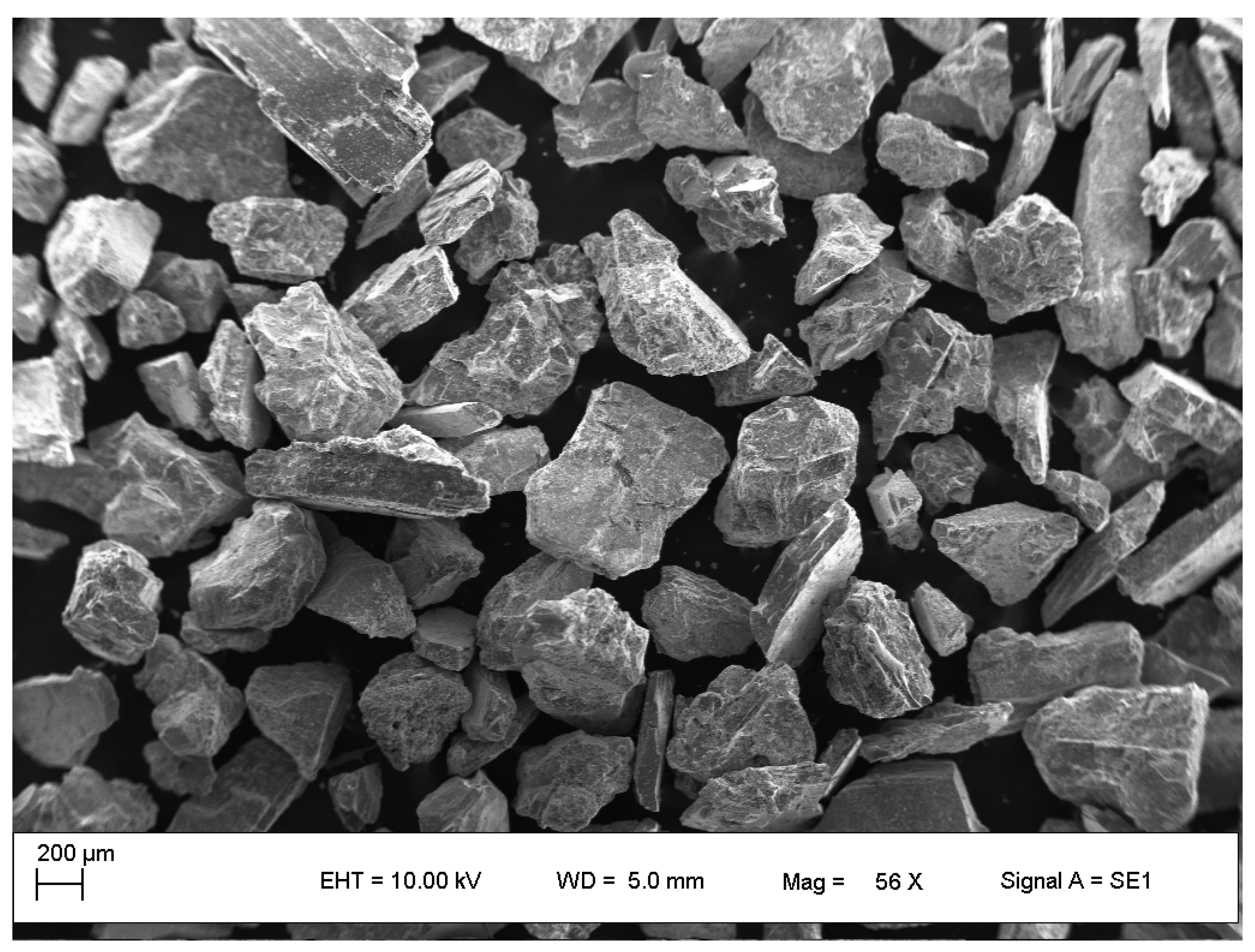
2.3. Erodent Particles
2.4. Microstructural and Qualitative Phase Characterization
2.5. Jet Slurry Erosion Tests
3. Results and Discussion
3.1. X-ray Diffraction Analysis
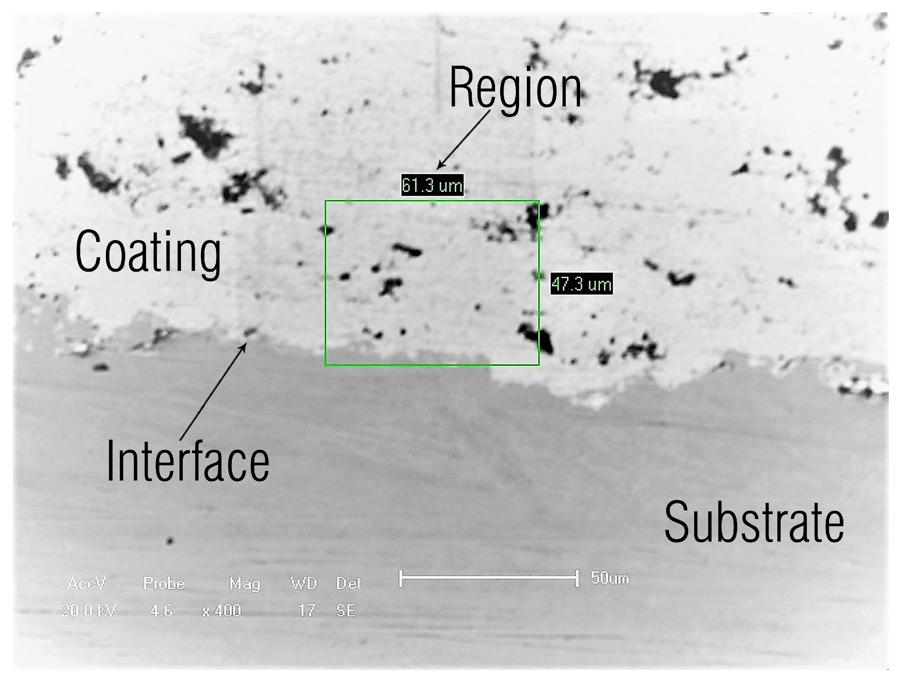
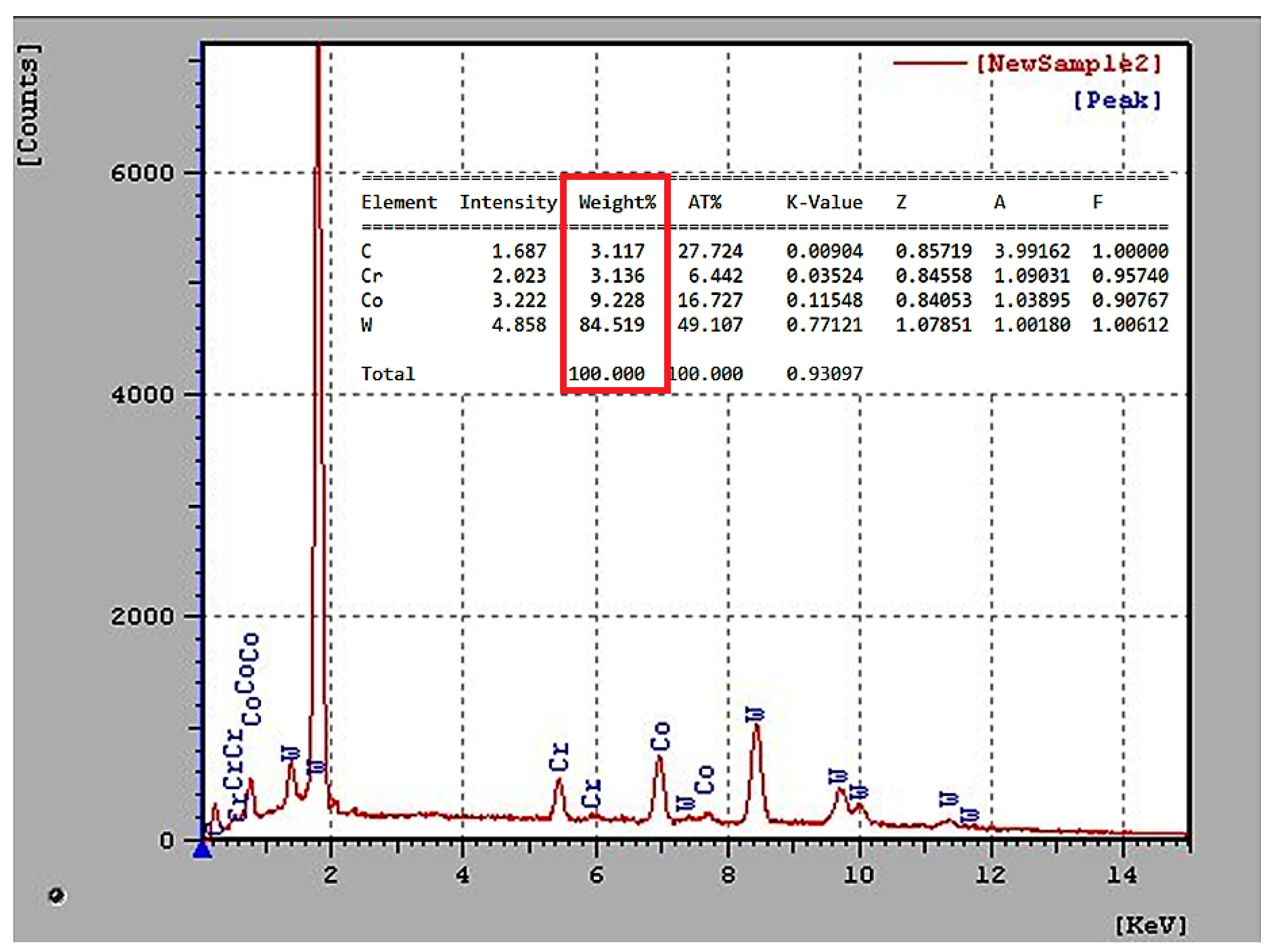
3.2. EDS Analysis Coating
3.3. Mechanical Properties of Materials
4. Conclusions
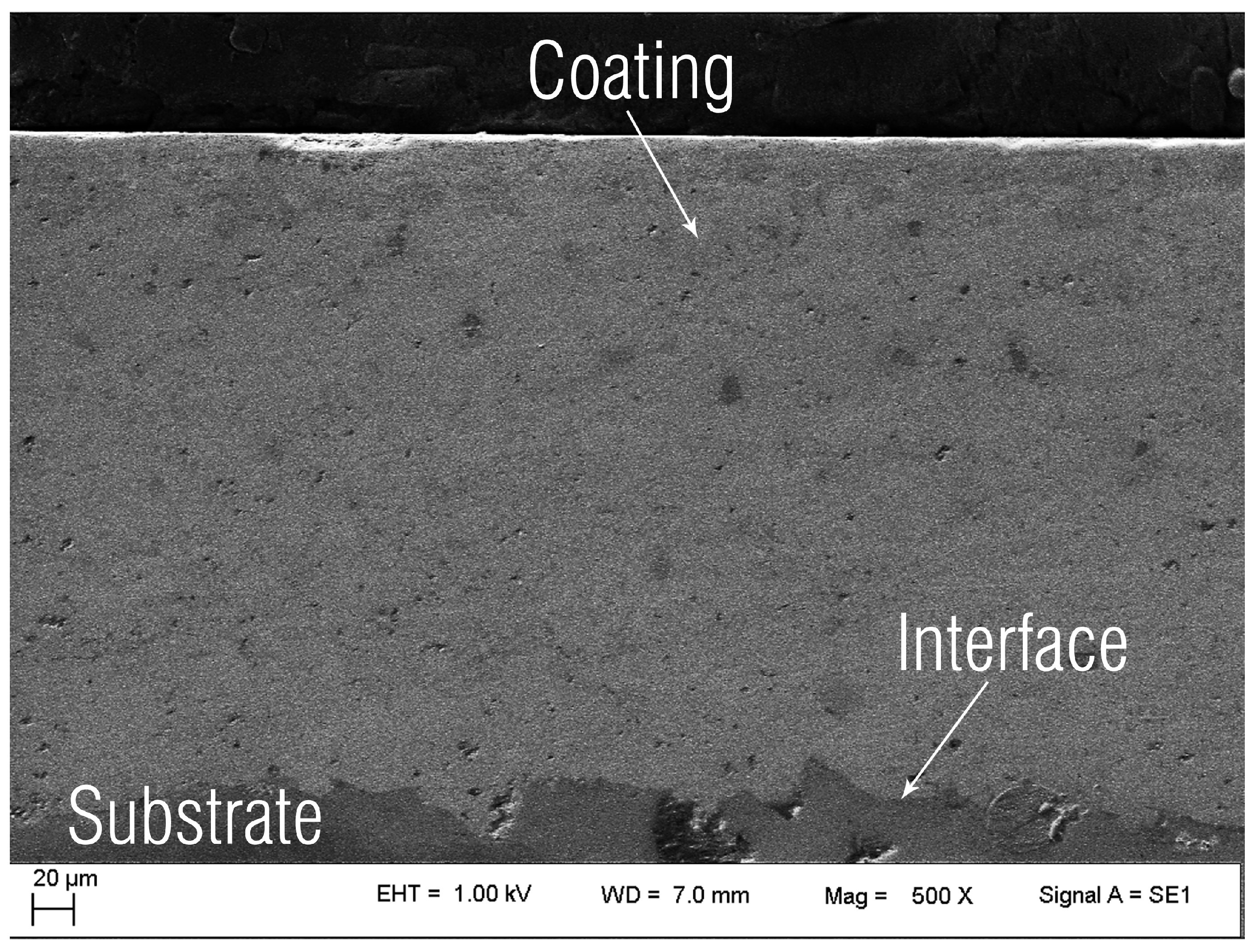
- The tungsten carbide coating showed higher resistance to jet slurry erosion compared to martensitic stainless steel, possibly due to the low porosity, the hardness of WC particles, and better properties of the CoCr binder material matrix. Thus, the application of such a coating can be considered as beneficial for the structural endurance of the substrate in applications where the part is subjected to similar erosive conditions.
- The high concentration of WC-Co in the coating blend promotes greater hard-phase connectivity, leading to increased mechanical strength and jet slurry erosion resistance.
- The martensitic stainless steel presented a higher rate of accumulated volumetric erosion in the impact angle of 30, denoting ductile behavior. On the other hand, the accumulated volumetric erosion rate for tungsten carbide coating was higher at the impact angle of 90, indicating a predominantly brittle failure mechanism.
- For the impact angle of 30, the tungsten carbide coating presented a cumulative volumetric erosion rate of approximately 50% less than martensitic stainless steel.
5. Patents
Author Contributions
Funding
Acknowledgments
Conflicts of Interest
References
- Popov, V.L. Adhesive wear: Generalized Rabinowicz’criteria. Facta Univ. Ser. Mech. Eng. 2018, 16, 29–39. [Google Scholar] [CrossRef]
- López-Ortega, A.; Bayón, R.; Arana, J.L. Evaluation of Protective Coatings for High-Corrosivity Category Atmospheres in Offshore Applications. Materials 2019, 12, 1325. [Google Scholar] [CrossRef]
- Mohrbacher, H. Martensitic automotive steel sheet-fundamentals and metallurgical optimization strategies. Advanced Materials Research. Trans. Tech. Publ. 2015, 1063, 130–142. [Google Scholar]
- Klueh, R.; Nelson, A.T. Ferritic/martensitic steels for next-generation reactors. J. Nucl. Mater. 2007, 371, 37–52. [Google Scholar] [CrossRef]
- Abe, F. Precipitate design for creep strengthening of 9% Cr tempered martensitic steel for ultra-supercritical power plants. Sci. Technol. Adv. Mater. 2008, 9, 013002. [Google Scholar] [CrossRef]
- Krauss, G. Steels: Processing, Structure, and Performance; Asm International: Novelty, OH, USA, 2015. [Google Scholar]
- Levy, A.V.; Yau, P. Erosion of steels in liquid slurries. Wear 1984, 98, 163–182. [Google Scholar] [CrossRef] [Green Version]
- Kumar, R.; Kamaraj, M.; Seetharamu, S.; Pramod, T.; Sampathkumaran, P. Effect of Spray Particle Velocity on Cavitation Erosion Resistance Characteristics of HVOF and HVAF Processed 86WC-10Co4Cr Hydro Turbine Coatings. J. Therm. Spray Technol. 2016, 25, 1217–1230. [Google Scholar] [CrossRef]
- Bergmann, C.P.; Vicenzi, J. Protection against erosive wear using thermal sprayed cermet: A review. In Protection against Erosive Wear Using Thermal Sprayed Cermet; Springer: Berlin, Germany, 2011; pp. 1–77. [Google Scholar]
- Cunha, M.A.; Guaglianoni, W.C.; Bezerra, B.F.A.; de Camargo, F.V.; Bergmann, C.P. Resistance to Abrasive and Erosive Wear of WCCo/NiCr HVOF Coatings: Comparative Evaluation of Commercial Nanostructured Spray Powders. Tribol. Ind. 2019, in press. [Google Scholar]
- Totemeier, T.C.; Wright, R.N.; Swank, W. FeAl and Mo-Si-B intermetallic coatings prepared by thermal spraying. Intermetallics 2004, 12, 1335–1344. [Google Scholar] [CrossRef]
- Ahledel, N.; Schulz, R.; Gariepy, M.; Hermawan, H.; Alamdari, H. Electrochemical Corrosion Behavior of Fe3Al/TiC and Fe3Al-Cr/TiC Coatings Prepared by HVOF in NaCl Solution. Metals 2019, 9, 437. [Google Scholar] [CrossRef]
- Zhang, J.; Deng, C.; Song, J.; Deng, C.; Liu, M.; Dai, M. Electrochemical Corrosive Behaviors of Fe-Based Amorphous/Nanocrystalline Coating on Stainless Steel Prepared by HVOF-Sprayed. Coatings 2019, 9, 226. [Google Scholar] [CrossRef]
- Liu, W.H.; Shieu, F.S.; Hsiao, W.T. Enhancement of wear and corrosion resistance of iron-based hard coatings deposited by high-velocity oxygen fuel (HVOF) thermal spraying. Surf. Coat. Technol. 2014, 249, 24–41. [Google Scholar] [CrossRef]
- Hou, G.; An, Y.; Zhao, X.; Zhou, H.; Chen, J. Effect of alumina dispersion on oxidation behavior as well as friction and wear behavior of HVOF-sprayed CoCrAlYTaCSi coating at elevated temperature up to 1000 ∘C. Acta Mater. 2015, 95, 164–175. [Google Scholar] [CrossRef]
- Nahvi, S.; Jafari, M. Microstructural and mechanical properties of advanced HVOF-sprayed WC-based cermet coatings. Surf. Coat. Technol. 2016, 286, 95–102. [Google Scholar] [CrossRef]
- Hong, S.; Wu, Y.; Zhang, J.; Zheng, Y.; Zheng, Y.; Lin, J. Synergistic effect of ultrasonic cavitation erosion and corrosion of WC–CoCr and FeCrSiBMn coatings prepared by HVOF spraying. Ultrason. Sonochem. 2016, 31, 563–569. [Google Scholar] [CrossRef]
- FEITAL Group. 2019. Available online: www.feital.com.br/produtos/ (accessed on 23 May 2019).
- Oerlikon Metco Company. 2019. Available online: https://www.oerlikon.com/metco/en/products-services/coating-materials/coating-materials-thermal-spray/cermets/ (accessed on 23 May 2019).
- International Organization for Standardization. Particle Size Analysis—Laser Diffraction Methods; ISO Standards Authority: Geneva, Switzerland, 2009. [Google Scholar]
- ASTM International. E2109-01 (2014) Standard Test Methods for Determining Area Percentage Porosity in Thermal Sprayed Coatings; ASTM International: West Conshohocken, PA, USA, 2014. [Google Scholar]
- ASTM International. Standard Test Method for Knoop and Vickers Hardness of Materials; ASTM International: West Conshohocken, PA, USA, 2011. [Google Scholar]
- ASTM International. ASTM G76-13 (2013) Standard Test Method for Conducting Erosion Tests by Solid Particle Impingement Using Gas Jets; ASTM International: West Conshohocken, PA, USA, 2013. [Google Scholar]
- Zu, J.; Hutchings, I.; Burstein, G. Design of a slurry erosion test rig. Wear 1990, 140, 331–344. [Google Scholar] [CrossRef]
- Wentzel, E.; Allen, C. The erosion-corrosion resistance of tungsten-carbide hard metals. Int. J. Refract. Met. Hard Mater. 1997, 15, 81–87. [Google Scholar] [CrossRef]
- Santa, J.; Baena, J.; Toro, A. Slurry erosion of thermal spray coatings and stainless steels for hydraulic machinery. Wear 2007, 263, 258–264. [Google Scholar] [CrossRef]
- Santa, J.; Espitia, L.; Blanco, J.; Romo, S.; Toro, A. Slurry and cavitation erosion resistance of thermal spray coatings. Wear 2009, 267, 160–167. [Google Scholar] [CrossRef]
- Hutchings, I. A model for the erosion of metals by spherical particles at normal incidence. Wear 1981, 70, 269–281. [Google Scholar] [CrossRef] [Green Version]
- Finnie, I. Some reflections on the past and future of erosion. Wear 1995, 186, 1–10. [Google Scholar] [CrossRef]
- Maiti, A.; Mukhopadhyay, N.; Raman, R. Improving the wear behavior of WC-CoCr-based HVOF coating by surface grinding. J. Mater. Eng. Perform. 2009, 18, 1060. [Google Scholar] [CrossRef]
- Madsen, B.W. Measurement of erosion-corrosion synergism with a slurry wear test apparatus. Wear 1988, 123, 127–142. [Google Scholar] [CrossRef]
- Murthy, J.; Rao, D.; Venkataraman, B. Effect of grinding on the erosion behaviour of a WC-Co-Cr coating deposited by HVOF and detonation gun spray processes. Wear 2001, 249, 592–600. [Google Scholar] [CrossRef]
- Liu, X.; Zhang, B. Effects of grinding process on residual stresses in nanostructured ceramic coatings. J. Mater. Sci. 2002, 37, 3229–3239. [Google Scholar] [CrossRef]
- File, P.D. Joint Committee on Powder Diffraction Standards; ASTM International: West Conshohocken, PA, USA, 1967; pp. 9–185. [Google Scholar]
- Chivavibul, P.; Watanabe, M.; Kuroda, S.; Kawakita, J.; Komatsu, M.; Sato, K.; Kitamura, J. Effects of particle strength of feedstock powders on properties of warm-sprayed WC-Co coatings. J. Therm. Spray Technol. 2011, 20, 1098–1109. [Google Scholar] [CrossRef]
- Guilemany, J.; De Paco, J.; Miguel, J.; Nutting, J. Characterization of the W2C phase formed during the high velocity oxygen fuel spraying of a WC + 12pct Co powder. Metall. Mater. Trans. A 1999, 30, 1913–1921. [Google Scholar] [CrossRef]
- Thakur, L.; Arora, N.; Jayaganthan, R.; Sood, R. An investigation on erosion behavior of HVOF sprayed WC-CoCr coatings. Appl. Surf. Sci. 2011, 258, 1225–1234. [Google Scholar] [CrossRef]
- Castro, G.; Arenas, F.; Rodriguez, M.; Scagni, A. Microestructura De materiales compuestos WC-Co/Ni-W-Cr recubiertos Por HVOF. Rev. Latinoam. Metal. Mater. 2001, 21, 50–55. [Google Scholar]
- Castro, R.; Rocha, A.; Cavaler, L.; Kejelin, N.; Marques, F. Avaliação das características de superfície e do desgaste abrasivo de revestimentos aplicados em hastes de cilindros hidráulicos pelas técnicas de aspersão (HVOF) e eletrodeposição. Master’s Thesis, Federal University of Rio Grande do Sul, Porto Alegre, Brazil, 2012. [Google Scholar]
- Solution, T.S. Hydraulic Seals/Rod Seals. Available online: http://tk-ines.ru/upload/iblock/26e/26e36169a1738d5faa13585f921374e1.PDF (accessed on 23 May 2019).
- Berger, L.M.; Saaro, S.; Naumann, T.; Wiener, M.; Weihnacht, V.; Thiele, S.; Suchánek, J. Microstructure and properties of HVOF-sprayed chromium alloyed WC-Co and WC–Ni coatings. Surf. Coat. Technol. 2008, 202, 4417–4421. [Google Scholar] [CrossRef]
- Ahmed, R.; Ali, O.; Faisal, N.H.; Al-Anazi, N.; Al-Mutairi, S.; Toma, F.L.; Berger, L.M.; Potthoff, A.; Goosen, M. Sliding wear investigation of suspension sprayed WC-Co nanocomposite coatings. Wear 2015, 322, 133–150. [Google Scholar] [CrossRef]
- Islam, M.A.; Farhat, Z.N. Effect of impact angle and velocity on erosion of API X42 pipeline steel under high abrasive feed rate. Wear 2014, 311, 180–190. [Google Scholar] [CrossRef]
- Okonkwo, P.C.; Shakoor, R.A.; Zagho, M.M.; Mohamed, A.M.A. Erosion Behaviour of API X100 Pipeline Steel at Various Impact Angles and Particle Speeds. Metals 2016, 6, 232. [Google Scholar] [CrossRef]
- Bayer, R.G. Mechanical Wear Prediction and Prevention; Marcel Dekker, Inc.: Monticello, NY, USA, 1994. [Google Scholar]
- Papini, M.; Spelt, J. The plowing erosion of organic coatings by spherical particles. Wear 1998, 222, 38–48. [Google Scholar] [CrossRef]
- O’Flynn, D.; Bingley, M.; Bradley, M.; Burnett, A. A model to predict the solid particle erosion rate of metals and its assessment using heat-treated steels. Wear 2001, 248, 162–177. [Google Scholar] [CrossRef]
- Biswas, S.; Satapathy, A.; Patnaik, A. Erosion wear behavior of polymer composites: A review. J. Reinf. Plast. Compos. 2010, 29, 2898–2924. [Google Scholar] [CrossRef]
- Barber, J.; Mellor, B.; Wood, R. The development of sub-surface damage during high energy solid particle erosion of a thermally sprayed WC-Co-Cr coating. Wear 2005, 259, 125–134. [Google Scholar] [CrossRef]
- Javaheri, V.; Porter, D.; Kuokkala, V.T. Slurry erosion of steel—Review of tests, mechanisms and materials. Wear 2018, 408, 248–273. [Google Scholar] [CrossRef]
- Wood, F.W. Erosion by solid-particle impacts: A testing update. J. Test. Eval. 1986, 14, 23–27. [Google Scholar]
- De Souza, V.; Neville, A. Corrosion and erosion damage mechanisms during erosion–corrosion of WC-Co-Cr cermet coatings. Wear 2003, 255, 146–156. [Google Scholar] [CrossRef]
- Vite-Torres, M.; Laguna-Camacho, J.; Baldenebro-Castillo, R.; Gallardo-Hernandez, E.A.; Vera-Cárdenas, E.; Vite-Torres, J. Study of solid particle erosion on AISI 420 stainless steel using angular silicon carbide and steel round grit particles. Wear 2013, 301, 383–389. [Google Scholar] [CrossRef]


| Elements | Composition (%) |
|---|---|
| W | Balance |
| Co | 8.5–11.5 |
| Cr | 3.4–4.6 |
| C (Total) | 4.8–5.6 |
| Fe (Max) | 0.2 |
| Spray Parameters | Value |
|---|---|
| Propylene flow rate | 4620 (L/h) |
| Oxygen flow rate | 15,180 (L/h) |
| Powder feed rate | 42 (g/min) |
| Spray distance | 230 (mm) |
| Material / Coating | 86WC-10Co4Cr | Steel AISI 410 |
|---|---|---|
| Microhardness average | 1139 | 219 |
| Standard Deviation | 171 | 31 |
| Coefficient of Variation (%) | 15 | 14 |
| Material/Coating | Impact Angle | Volumetric Erosion Rate | Standard Deviation |
|---|---|---|---|
| () | (cm/g) × 10 | (cm/g) × 10 | |
| Steel AISI 410 | 30 | 0.8449 | 0.0114 |
| 90 | 0.7025 | 0.0495 | |
| 86WC-10Co4Cr | 30 | 0.4490 | 0.0023 |
| 90 | 0.6778 | 0.0283 |
| Roughness Ra (m) | |||||
|---|---|---|---|---|---|
| Material/Coating | Before | Standard | Angle | After | Standard |
| Erosion | Deviation | () | Erosion | Deviation | |
| 86WC-10Co4Cr | 0.08 | 0.02 | 30 | 1.60 | 0.11 |
| 90 | 1.91 | 0.13 | |||
| Steel AISI 410 | 0.07 | 0.03 | 30 | 2.97 | 0.47 |
| 90 | 2.56 | 0.11 | |||
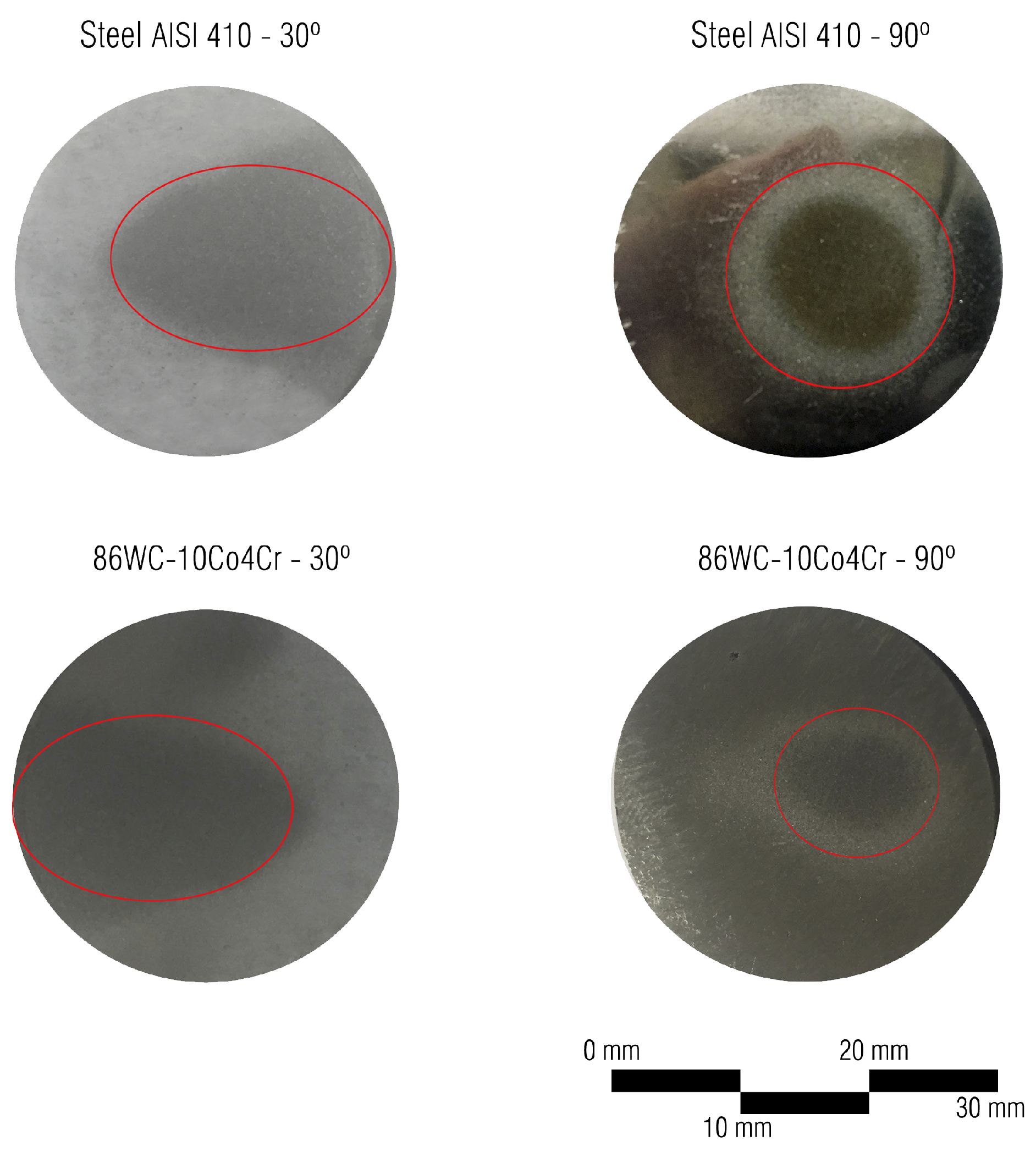
| Material/Coating | Impact Angle () | Eroded Area (mm) |
|---|---|---|
| Steel AISI 410 | 30 | 277.7 |
| 90 | 147.1 | |
| 86WC-10Co4Cr | 30 | 201.2 |
| 90 | 94.9 |
| Material/Coating | Impact Angle () | Average Depth (m) | Standard Deviation (m) |
|---|---|---|---|
| Steel AISI 410 | 30 | 93 | ±2.88 |
| 90 | 102 | ±15.87 | |
| 86WC-10Co4Cr | 30 | 33 | ±5.77 |
| 90 | 62 | ±3.21 |
© 2019 by the authors. Licensee MDPI, Basel, Switzerland. This article is an open access article distributed under the terms and conditions of the Creative Commons Attribution (CC BY) license (http://creativecommons.org/licenses/by/4.0/).
Share and Cite
Santacruz, G.; Shigueaki Takimi, A.; Vannucchi de Camargo, F.; Pérez Bergmann, C.; Fragassa, C. Comparative Study of Jet Slurry Erosion of Martensitic Stainless Steel with Tungsten Carbide HVOF Coating. Metals 2019, 9, 600. https://doi.org/10.3390/met9050600
Santacruz G, Shigueaki Takimi A, Vannucchi de Camargo F, Pérez Bergmann C, Fragassa C. Comparative Study of Jet Slurry Erosion of Martensitic Stainless Steel with Tungsten Carbide HVOF Coating. Metals. 2019; 9(5):600. https://doi.org/10.3390/met9050600
Chicago/Turabian StyleSantacruz, Galileo, Antonio Shigueaki Takimi, Felipe Vannucchi de Camargo, Carlos Pérez Bergmann, and Cristiano Fragassa. 2019. "Comparative Study of Jet Slurry Erosion of Martensitic Stainless Steel with Tungsten Carbide HVOF Coating" Metals 9, no. 5: 600. https://doi.org/10.3390/met9050600