Article

Characterization of Microstructure and Mechanical Properties of Stellite 6 Part Fabricated by Wire Arc Additive Manufacturing

1
School of Mechanical Engineering, Beijing Institute of Technology, Beijing 100081, China
2
Mechanical and Aerospace Engineering Department, University of California at Los Angeles (UCLA), Los Angeles, CA 90095, USA
3
Beijing Institute of Astronautical Systems Engineering, Beijing 100076, China
*
Author to whom correspondence should be addressed.
Metals 2019, 9(4), 474; https://doi.org/10.3390/met9040474
Submission received: 22 March 2019 / Revised: 15 April 2019 / Accepted: 20 April 2019 / Published: 24 April 2019
(This article belongs to the Special Issue Arc-based Additive Manufacturing)

Abstract

:
Stellite 6 alloy has excellent wear resistance, corrosion resistance, and oxidation resistance, however the difficulties in traditional processing limit its wide application. Additive manufacturing technology that has emerged in recent years is expected to provide a new way for the processing of stellite 6 alloy. In this study, two square thin-walled stellite 6 parts were fabricated through the wire arc additive manufacturing technology. At the same time, the effect of stress relief annealing on the mechanical performance of the fabricated stellite 6 part was studied and compared with the corresponding casting part. The results indicate that the additive manufacturing stellite 6 components exhibit satisfactory quality and appearance. Moreover, the microstructure of the additive manufacturing part is much finer than that of the casting part. From the substrate to the top region of the additive manufacturing part, the morphology of the dendrites changes from columnar to equiaxed, and the hardness increases firstly and then decreases gradually. In addition, the average hardness of the additive manufacturing part is ~7–8 HRC higher than the casting part. The ultimate tensile strength and yield strength is ~150MPa higher than the casting part, while the elongation is almost the same. The stress relief annealing has no significant effect on the hardness of the AM part, but it can slightly improve the strength.

1. Introduction

As a kind of cemented carbide, Co-based alloys have excellent wear resistance, thermal fatigue resistance, and corrosion resistance [1,2,3,4]. Stellite 6 alloy is a typical Co-based alloy, and is widely used under extremely corrosive and wearing conditions, such as the aero engine, industrial gas turbine, and nuclear industries [5,6]. At the expense of the great physical and mechanical properties, stellite 6 alloy is difficult to be fabricated by traditional methods. Great efforts have been undertaken to investigate the coating and manufacturing methods of stellite 6 alloy. Aykut et al. systematically investigated the tool wear, chip morphology and cutting force of the stellite alloy in face milling process [7]. It is shown that cutting force increases with the depth of cut and feed, but is independent of cutting speed. Malayoglu et al. studied the advantages of the hot isostatically pressed method of manufacturing stellite 6 alloy and found that excellent corrosion resistance can be obtained compared to the casting method [8]. Apay et al. improved the wear resistance of the AISI 1015 steel through surface hardfacing stellite 6 alloy [9]. All of these methods have played an important role in promoting the application of this alloy. However, to the best of our knowledge, there is no study of fabricating stellite 6 parts by means of additive manufacturing technology. Little is known about the performance of additive manufacturing stellite 6 parts. The present research attempts to fabricate the stellite 6 components with additive manufacturing technology, which is considered to provide a new and advanced fabrication method for the stellite 6 alloy.
As a near net-shape forming technology, additive manufacturing (AM) is widely used in the fabrication of traditional difficult-to-cut metals, such as titanium, molybdenum, magnesium alloys, etc. [10,11,12,13,14]. It is a promising method based on the principle of layer by layer accumulation with a heat source moving in a specific path [14]. Wire arc additive manufacturing (WAAM) uses arc as the heat source and wire as the feedstock. WAAM has been rapidly developed in recent years. Compared with the laser additive manufacturing and electron beam additive manufacturing, WAAM has the advantages of fabricating large structural components because of its higher deposition rate, higher material utilization rate, and lower cost [15,16,17].
Based on the consideration above, the present research is aimed at fabricating the stellite 6 components with WAAM technology. The performance of this component was compared with the casting part to investigate the feasibility of the additive manufacturing method. Furthermore, experiments are designed to verify whether the stress relief annealing has an effect on the performance of WAAM-fabricated stellite 6 component. The microstructure, hardness, and tensile properties were investigated for stellite 6 components.

2. Experimental Procedures

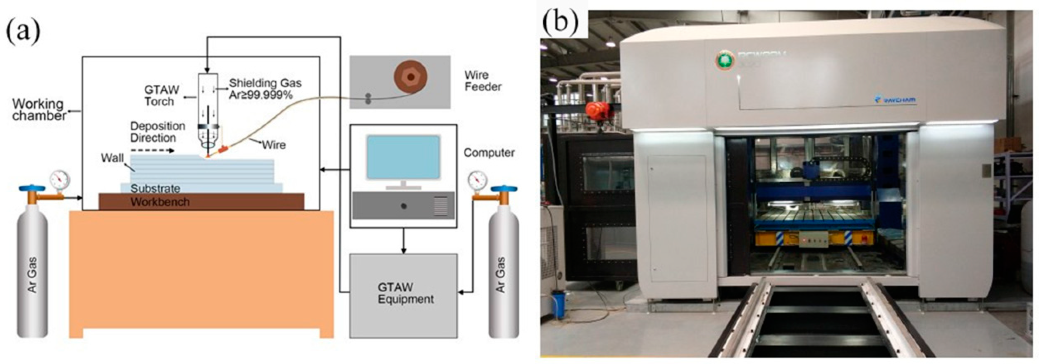
2.1. Experimental Set up and Manufacturing Process

The schematic of the WAAM equipment (Make: BIT, Beijing, China, Model: WAAM 2) used in this work is shown in Figure 1a. It mainly consists of computer numerical control (CNC) machine unit, gas tungsten arc welding (GTAW) equipment unit, wire feeding unit, and argon protection unit. The actual picture of the whole equipment is shown in Figure 1b. For the sake of preventing the oxidation from affecting the performance of the stellite 6 parts, the whole manufacturing process was executed in a sealed working chamber with an argon purity of 99.99%. The raw material used in this experiment is stellite 6 flux-cored wire with the diameter of 1.2 mm, its chemical composition is listed in Table 1. The material of the substrate was 304L and it was treated by mechanical polishing before fixed on the workbench. Its length, width, and thickness are 150 mm, 150 mm, and 5 mm, respectively. Its basic chemical composition is shown in Table 1. Based on our previous research of the WAAM processing, the parameters used in this work were optimized and listed in Table 2. Two thin-walled squares (50 mm in width, 50 mm in length, and 50 layers in height) were manufactured using the same parameter. One was used for testing performance directly, and the other was tested after stress relief annealing as explained below.
The main purpose of this paper is to verify the performance of the stellite 6 parts manufactured by WAAM technology. Three stellite 6 parts with different processing conditions were used for the comparison of the microstructure, hardness, and tensile properties. It includes a deposition part (WAAM part), a heat treatment part (WAAM part after stress relief annealing), and a casting part. The heat treated part, having the same manufacturing parameters with deposition part, is used to verify whether residual stress of the WAAM has an effect on the performance of stellite 6 component. The process of stress relief annealing process consist on heating up to 600 °C for two hours, then air cooled to room temperature. The size of the casting sample is 30 mm × 20 mm × 50 mm and its chemical composition is shown in Table 1.

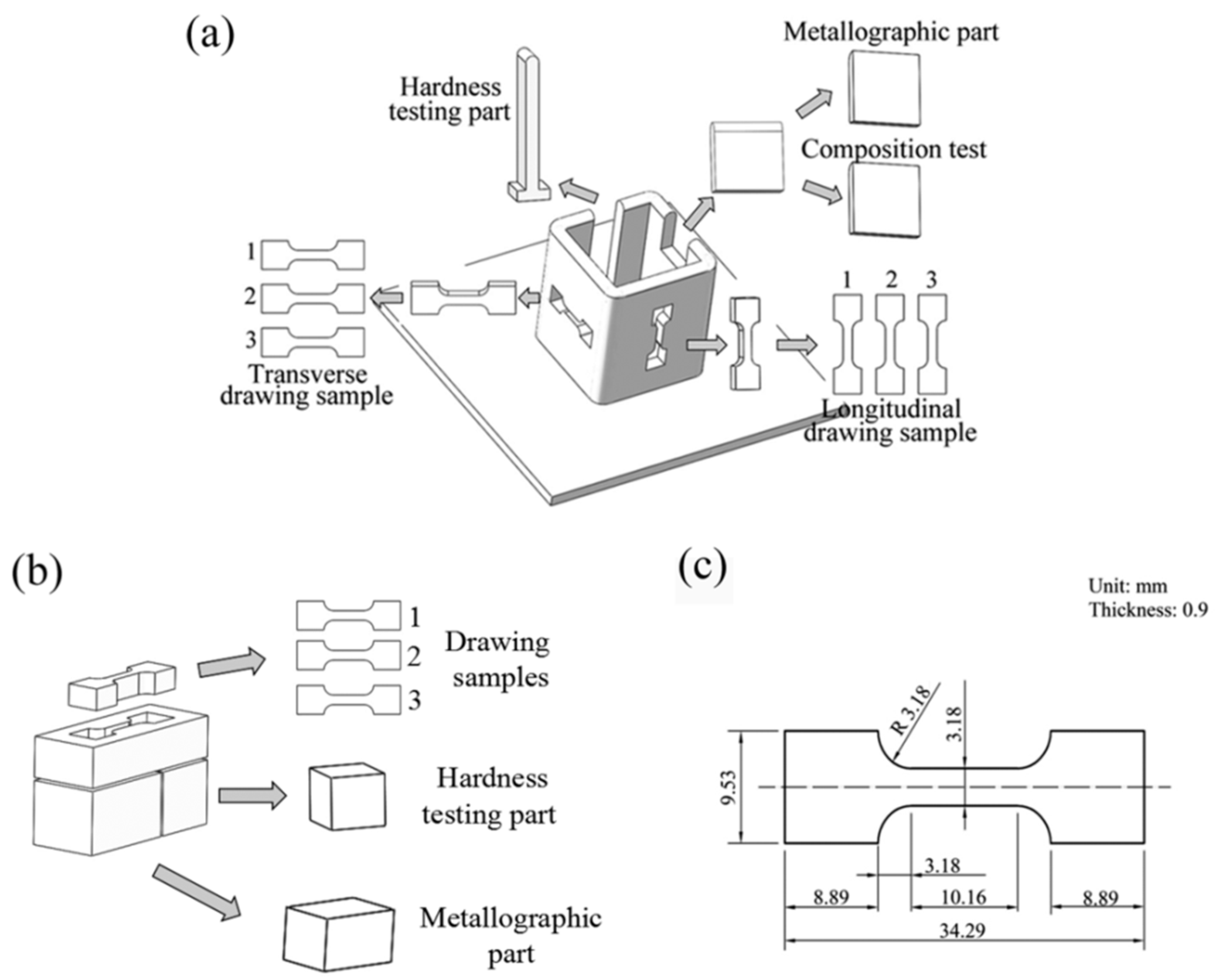
2.2. Characterization

The deposition part and heat treated part were cut in the same way because they have the same shape. As is shown in Figure 2a, in order to measure the hardness at different locations, a strip-like sample, 15 mm wide, was cut-out. The surface of the hardness testing sample has been mechanically polished to meet the test requirement. Over three drawing samples were cut from the transverse and longitudinal direction respectively to verify whether there is anisotropy of tensile properties. The size of the sample is illustrated in Figure 2c. The test data was averaged, and the fracture surface was analyzed by the scanning electron microscope (SEM) (Make: FEI, Hillsboro, OR, USA; Model: QUANTA FEG 650). At the same time, a 20 mm × 20 mm square was cut-out, then half of it was used to make metallographic sample and the other half was used to measure the chemical composition. The metallographic sample was polished with SiC papers. Afterwards, a mixture solution of H2O:CH3COOH:HCl:HNO3 with a ratio of 1:1:4:1 was used for the etching. The microstructure was characterized by optical microscope (Make: CEWEI, Shanghai, China, Model: LW600LJT) and SEM. The cutting plot of the casting block is shown in Figure 2b, which also includes drawing samples, hardness testing parts, and metallographic parts. The dendritic arm spacing was measured by Image-Pro Plus 6.0 software (6.0, Media Cybernetics, Rockville, MD, USA).

3. Results and Conclusions

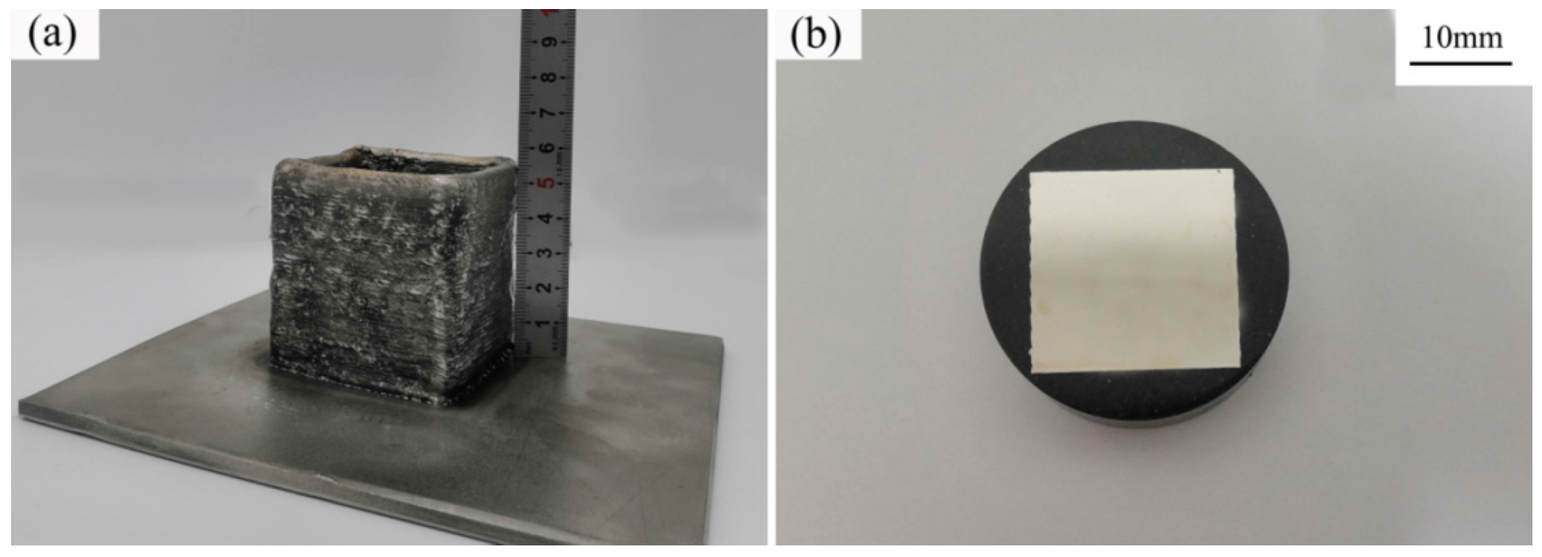
3.1. Macrostructure and Composition

The macro-image of the stellite 6 square part manufactured by the WAAM is shown in Figure 3a. It can been seen that the general shape is good, and there are no collapse and spatter phenomenon which have been reported in other researches [18]. The width of the thin wall is about 6.5 mm and the height is about 56 mm. According to previous research, the size of the WAAM component is decided by the shape of the molten pool [19]. Generally, high arc heat input results in a molten pool with decreased height and increased width [19,20]. The whole height of the part is equal to the layer thickness multiplied by the quantity of the layer. This expectation is in good agreement with the experiment result. In addition, although the entire additive manufacturing process is carried out under argon protected atmosphere, the surface of the part does not exhibit metallic luster, which is due to the presence of partial volatiles in the flux-cored wire during the AM process.
The part used for composition test after mechanical polishing is presented in Figure 3b. It can be found from the appearance that there are no macro defects in the AM stellite 6 component. Furthermore, no layer bands appear on the inner surface, which is often reported in the AM components of titanium alloys [21]. Table 3 shows the chemical composition of the WAAM stellite 6 part. The composition of the component is almost consistent with the original feedstock. The subtle differences of the composition (like Fe, Mn, and Cr) are due to interlayer dilution caused by excessive arc heat input during the WAAM process. This leads to the small amount diffusion of elements between the layers and the substrate.

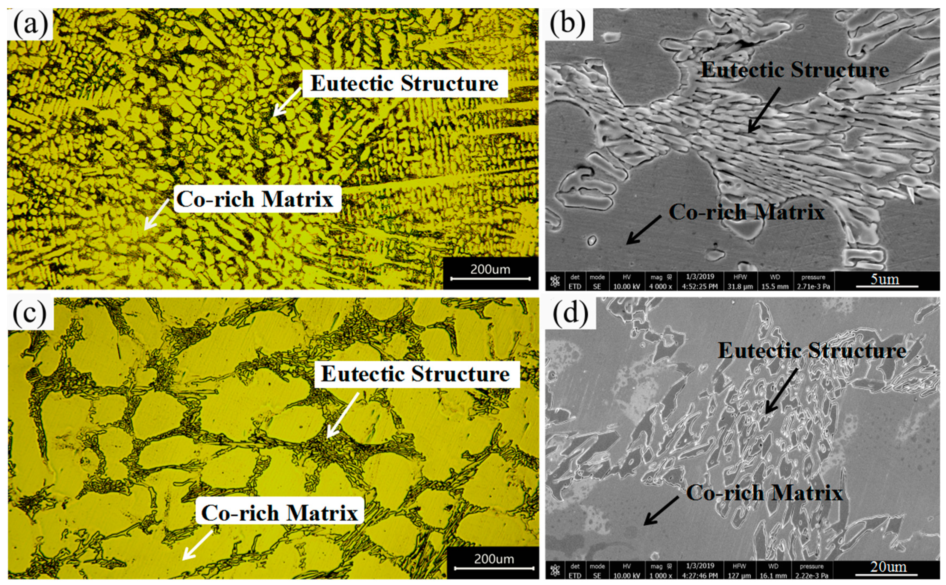
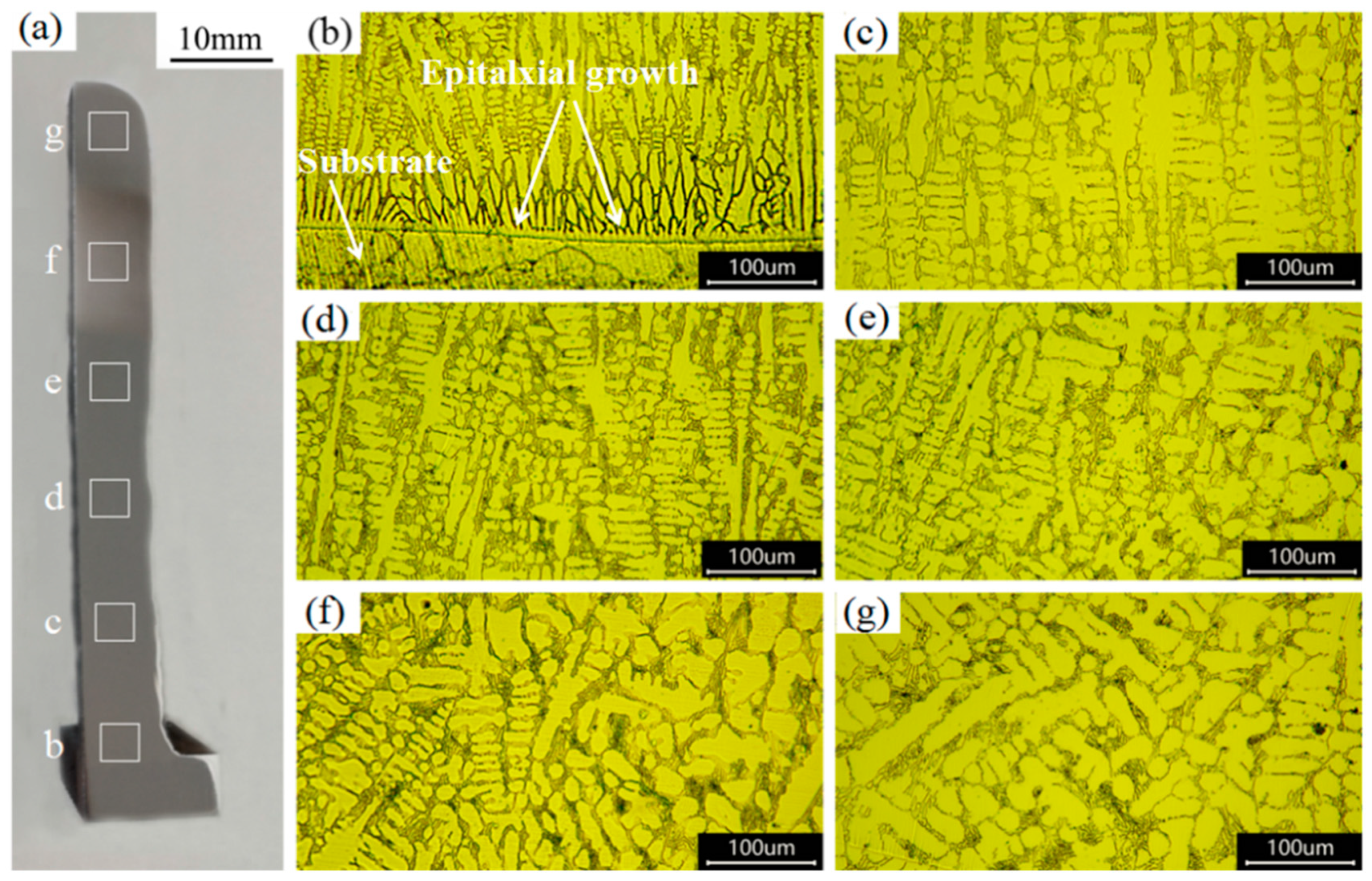
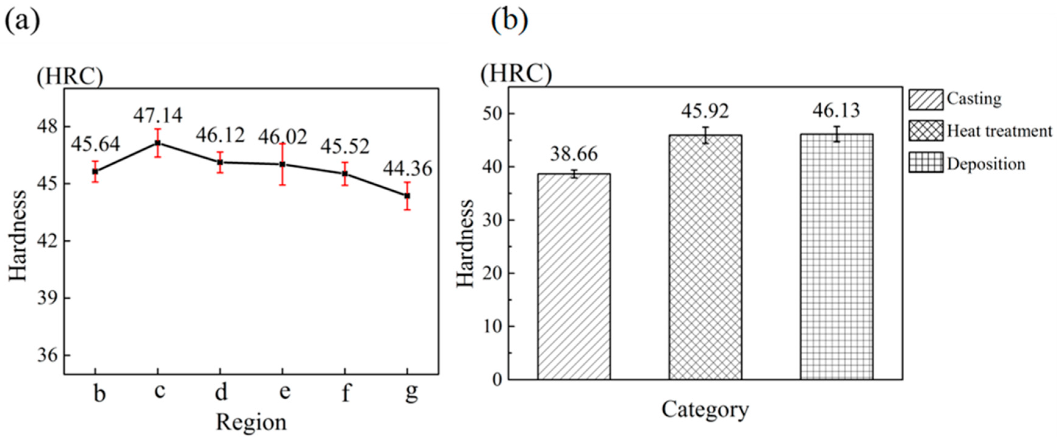
3.2. Microstructure and Hardness

The stress relief annealing does not change the microstructure of the stellite 6 alloy, only the microstructure of the WAAM component and casting block is presented. Figure 4a,c shows the optical microstructure (low magnification) and Figure 4b,d shows the SEM microstructure (high magnification) of the WAAM part and casting part, respectively. Both of their microstructures consisted of hypoeutectic structure. The hypoeutectic structure includes primary dendrites and interdendritic eutectics. The light region with the dendrites form is a Co-rich γ solid solution (fcc) and the dark region is the interdendritic eutectics, mainly consisting of γ-Co with the carbides of M7C3 (hcp). Here the M generally includes Co, Cr, and Fe [3,9]. The high hardness and excellent wear resistance of stellite 6 alloy are mainly due to the presence of the carbides, which are usually distributed in interdendritic areas and grain boundaries [22,23].
Compared with the casting block, it is noticeable that the dendritic branches of the WAAM component are extremely fine. As is known, the cooling rate during the WAAM process is much higher than that during casting for the reason of the little size of molten pool. The high cooling rate leads to the refinement of the microstructure. Moreover, this refinement phenomenon is also greatly observed in the eutectic structure. As is shown in Figure 4b,d, due to the fine microstructure of the WAAM part, the eutectic carbides mostly exhibit lamellar shape, whereas the casting block exhibits an obviously coarse appearance [5]. According to the previous studies, the shape and size of the carbides will affect the hardness of the parts [24,25]. The refinement of the microstructure and the difference in the morphology of the eutectic carbides may improve the mechanical performance of the WAAM parts.
A strip-shaped additive manufacturing stellite 6 part with a substrate is used to measure the difference in hardness at different locations. As is shown in Figure 5a, from bottom-to-top, six regions were selected to measure the hardness. At the same time, the microstructures of these areas were studied respectively to explore its evolution. The hardness test results are presented in Figure 6a. It can be found that the hardness increases firstly and then decreases gradually from the bottom to the top region. As is mentioned above, there is the substrate-elemental dilution phenomenon at the beginning of the WAAM process, which leads to the lower hardness of region b, and there is an increase trend from region b to c, as shown in Figure 5a. Starting from region c, the process of WAAM becomes stable and the hardness decreases gradually, which is mainly caused by the evolution of the microstructure. The reason for the microstructure change is that the cooling rate gradually decreases during the process of the WAAM [26]. In addition, the dendritic arm spacing tends to become larger with the decrease of the cooling rate. Such increase in spacing may result in the decline of the hardness [27,28]. It can be seen from Figure 5b–g that the dendritic arm spacing increases greatly from the bottom to top region, which has good agreement with the theory mentioned above. The primary arm spacing was found to change from 5.31 μm to 10.09 μm, and the secondary arm spacing change from 1.75 μm to 3.76 μm. This also explains the gradual decrease of hardness.
According to Figure 5b–g, it is found that the morphology of the solid solution has the trend of changing from the columnar dendrites to equiaxed dendrites. At the beginning of the WAAM process, there is great heat loss and large temperature gradient for the reason of the cold substrate. Therefore, the epitaxial growth is the main grain growth mode [2], as shown in Figure 5b. Subsequently, the secondary dendrites began to appear and then gradually transformed to equiaxed dendrites, which is mainly caused by the heat accumulation and repeated thermal cycling during the process of WAAM.
Because the hardness of the strip part varies slightly from bottom to top, ten points are taken from the middle position (from 25 to 35 layers) to test the hardness. Then the data was averaged and compared with the hardness of the casting block. The same method was applied to the heat treated part. The results are presented in the Figure 6b, and it can be seen that the hardness of WAAM part and heat treatment part is nearly (7–8) HRC higher than the casting block. The hardness of the stellite 6 is mainly decided by the dendritic arm spacing size as mentioned. It is the significant microstructure refinement of the WAAM part that leads to the decrease in spacing, which contributes to the high hardness. According to measurement, the primary dendritic arm spacing of the casting block is as high as 30.37 μm, while the additive manufacturing part is only 8.28 μm on average. Moreover, no changes were found in hardness after the stress relief annealing. This indicates that the residual stress after the WAAM process has little effect on the hardness of the stellite 6 alloy.

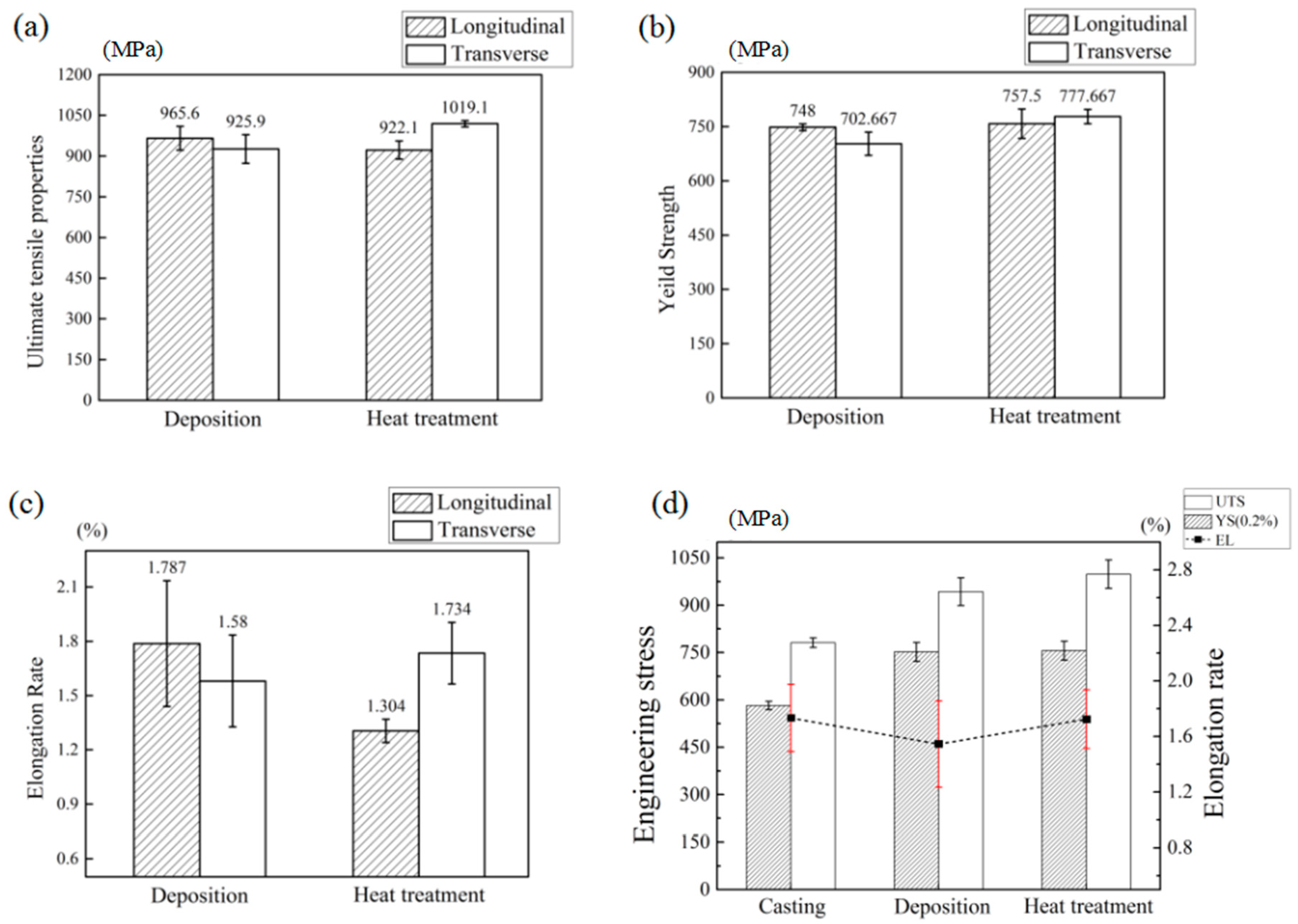
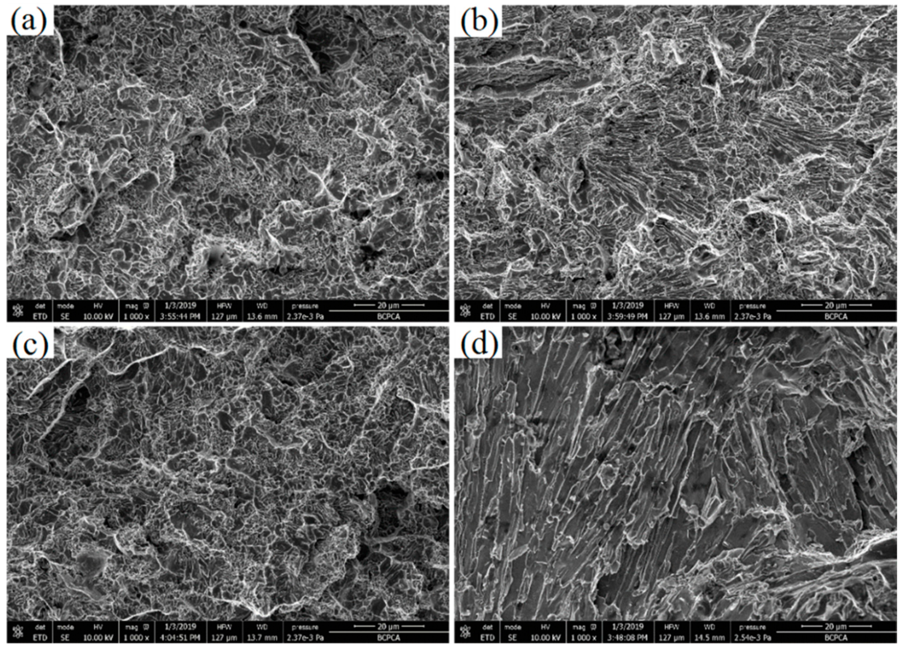
3.3. Tensile Properties

Because the AM technology is based on the principle of the scatter accumulation, which means manufacturing part layer-by-layer, the mechanical properties of the entire part are affected by the overlap quality between each molten pool in the transverse direction, as well as the remelting quality between each layer in the longitudinal direction. Furthermore, the columnar grain formed by the complex thermal cycling during the AM process can lead to the anisotropy of the mechanical properties, which has been reported in other studies [19,29]. Based on these considerations, in this work, over three longitudinal and transverse tensile samples are taken to test the anisotropy phenomenon. The results are averaged and presented in Table 4. It includes ultimate tensile strength (UTS), yield strength (YS), and elongation (EL). According to the result, it can be seen that both the transverse and the longitudinal direction have excellent mechanical properties, which means that the melting overlap quality in the two directions are better and no defects appear. In addition, the transverse and longitudinal mechanical properties of the deposited part and heat treatment part are basically the same, and no obvious anisotropy phenomenon emerges, as shown in Figure 7a–c. As mentioned above, although the morphology of dendrites changes from columnar to equiaxed, the columnar dendrites mainly exist at the bottom (from 0 to 10 layer) of the AM part. A large number of equiaxed dendrites appear in the middle and lower (from 8 to 25 layer) position of the part. The emergence of the equiaxed dendrites leads to no significant anisotropy in mechanical properties. Therefore, the evolution of the microstructures does not have a significant impact on the mechanical properties. The stellite 6 part with comprehensive mechanical properties can be obtained by the WAAM technology.
Since the differences of the two directions are not obvious, the values of tensile properties of the two directions are compared with the casting block on average. The results are shown in Figure 7d. It can be seen that the UTS and YS of the deposition and the heat treatment part are ~150 MPa higher than the casting part, but the EL of the three components are almost the same. According to the previous work, the fracture of the stellite 6 mainly occurs at the interface of the carbide and the matrix [30,31]. The thin microstructure of the WAAM component leads to larger amount of and more tortuous interface of the carbide and the matrix. The high quantity and tortuousness of the interface contribute to better mechanical properties through limiting the crack propagation. As known, the fracture mode of stellite 6 alloy belongs to the brittle fracture, which means the thin microstructure has little effect on the EL. Therefore, the EL of the WAAM part has hardly been improved. In addition, after the stress relief annealing, the mechanical properties of the stellite 6 part have been slightly improved, compared with the deposition part, as shown in Figure 7d. This shows that the residual stress after the WAAM process will affect the mechanical properties of the stellite 6 part to some extent. Therefore, it is necessary to carry out the relevant stress relief annealing after the WAAM process.
Figure 8a,b shows the fracture surface of the deposition part in the longitudinal and transverse direction, respectively. The morphologies of the fracture surface in these two directions are almost the same, which is expected because there is no anisotropy in the mechanical properties. In addition, although stress relief annealing can slightly improve the performance of the WAAM stellite 6 component, the fracture surface images do not show the differences, as shown in Figure 8c. This is because the stress relief annealing only removes the effect of residual stress on mechanical properties and does not change the microstructures. Figure 8d shows the fracture surface of the casting component. It can be seen that the fracture surface shows obvious brittle fracture phenomenon, which is caused by the coarse microstructure of the casting. Based on the analysis above, compared with the casting component, the WAAM stellite 6 part has great refinement in the microstructure. Although the elongation has not changed much, the hardness and mechanical properties have been greatly improved, which have great significance in promoting the application of stellite 6 alloys.

4. Conclusions

In this work, WAAM technology was adopted to fabricate stellite 6 components. Two thin-walled square parts were fabricated, and one for them is subjected to the stress relief annealing process. The microstructure, hardness and mechanical properties of these two components were investigated and compared with the stellite 6 casting part. The main conclusions are as follows.
  • The stellite 6 part manufactured by the WAAM has good forming quality and appearance. The composition of the stellite 6 components is slightly changed compared with the raw materials due to the element diffusion between each layers and substrate.
  • The microstructure of the WAAM Stellite 6 component is much thinner than that of the casting part. From the substrate to the top region, the morphology of dendrites changes from the columnar to equiaxed, and the dendritic arm spacing tend to increase.
  • The hardness of WAAM part rises firstly, and then decreases gradually from the bottom to top regions. Both WAAM part and stress relief annealing component is ~7–8 HRC higher than casting part. The stress relief annealing has no obvious effect on improving the hardness of AM stellite 6 parts.
  • There is almost no anisotropy of the mechanical properties. The UTS and YS of the WAAM component are much better than that of the casting part, but the EL is almost the same. The stress relief annealing process can improve the mechanical properties of the WAAM stellite 6 parts to some extent.

Author Contributions

Z.L. performed all experiments and wrote this manuscript. C.L. designed the research and gave some constructive suggestions. J.L., S.M., S.T., and H.F. helped analyze the experimental data. Y.C., J.W. (Jie Wang), J.W. (Jiachen Wang), T.X., T.L., and H.Z. participated in the discussion on the results and guided the writing of the article.

Acknowledgments

The work was financially supported by the National Natural Science Foundation of China (51875041, 51875042).

Conflicts of Interest

The authors declare no conflicts of interest.

References

  1. Shahroozi, A.; Afsari, A.; Khakan, B. Microstructure and mechanical properties investigation of stellite 6 and Stellite 6/TiC coating on ASTM A105 steel produced by TIG welding process. Surf. Coat. Technol. 2018, 350, 648–658. [Google Scholar] [CrossRef]
  2. Venkatesh, B.; Sriker, K.; Prabhakar, V.S.V. Wear Characteristics of Hardfacing Alloys: State-of-the-art. Procedia Mater. Sci. 2015, 10, 527–532. [Google Scholar] [CrossRef] [Green Version]
  3. Lin, W.C.; Chen, C. Characteristics of thin surface layers of cobalt-based alloys deposited by laser cladding. Surf. Coat. Technol. 2006, 200, 4557–4563. [Google Scholar] [CrossRef]
  4. Motallebzadeh, A.; Atar, E.; Cimenoglu, H. Sliding wear characteristics of molybdenum containing Stellite 12 coating at elevated temperatures. Tribol. Int. 2015, 91, 40–47. [Google Scholar] [CrossRef]
  5. Kuzucu, V.; Ceylan, M.; Çelik, H.; Aksoy, I. Microstructure and phase analyses of Stellite 6 plus 6 wt.% Mo alloy. J. Mater. Process. Technol. 1997, 69, 257–263. [Google Scholar] [CrossRef]
  6. Brownlie, F.; Hodgkiess, T.; Pearson, A.; Galloway, A.M. Effect of nitriding on the corrosive wear performance of a single and double layer Stellite 6 weld cladding. Wear 2017, 376, 1279–1285. [Google Scholar] [CrossRef] [Green Version]
  7. Aykut, Ş.; Bagci, E.; Kentli, A.; Yazıcıoğlu, O. Experimental observation of tool wear, cutting forces and chip morphology in face milling of cobalt based super-alloy with physical vapour deposition coated and uncoated tool. Mater. Des. 2007, 28, 1880–1888. [Google Scholar] [CrossRef]
  8. Malayoglu, U.; Neville, A. Comparing the performance of HIPed and Cast Stellite 6 alloy in liquid-solid slurries. Wear 2003, 255, 181–194. [Google Scholar] [CrossRef]
  9. Apay, S.; Gulenc, B. Wear properties of AISI 1015 steel coated with Stellite 6 by microlaser welding. Mater. Des. 2014, 55, 1–8. [Google Scholar] [CrossRef]
  10. Faidel, D.; Jonas, D.; Natour, G.; Behr, W. Investigation of the selective laser melting process with molybdenum powder. Addit. Manuf. 2015, 8, 88–94. [Google Scholar] [CrossRef]
  11. Liu, C.M.; Tian, X.J.; Tang, H.B.; Wang, H.M. Microstructural characterization of laser melting deposited Ti-5Al-5Mo-5V-1Cr-1Fe near β titanium alloy. J. Alloys Compd. 2013, 572, 17–24. [Google Scholar] [CrossRef]
  12. Liu, C.M.; Tian, X.J.; Wang, H.M.; Liu, D. Obtaining bimodal microstructure in laser melting deposited Ti-5Al-5Mo-5V-1Cr-1Fe near β titanium alloy. Mater. Sci. Eng. A 2014, 609, 177–184. [Google Scholar] [CrossRef]
  13. Wu, Q.; Lu, J.; Liu, C.; Fan, H.; Shi, X.; Fu, J.; Ma, S. Effect of Molten Pool Size on Microstructure and Tensile Properties of Wire Arc Additive Manufacturing of Ti-6Al-4V Alloy. Materials 2017, 10, 749. [Google Scholar] [Green Version]
  14. Guo, J.; Zhou, Y.; Liu, C.; Wu, Q.; Chen, X.; Lu, J. Wire Arc Additive Manufacturing of AZ31 Magnesium Alloy: Grain Refinement by Adjusting Pulse Frequency. Materials 2016, 9, 823. [Google Scholar] [CrossRef]
  15. Li, X.; Reynolds, A.P.; Cong, B.; Ding, J.; Williams, S. Production and Properties of a Wire-Arc Additive Manufacturing Part Made with Friction Extruded Wire. In Proceedings of the TMS 2015 144th Annual Meeting & Exhibition, Orlando, FL, USA, 15–19 March 2015. [Google Scholar]
  16. Wu, Q.; Lu, J.; Liu, C.; Shi, X.; Qian, M.; Tang, S.; Fan, H.; Ma, S. Obtaining uniform deposition with variable wire feeding direction during wire-feed additive manufacturing. Mater. Manuf. Processes 2017, 32, 1881–1886. [Google Scholar] [CrossRef]
  17. Ge, J.; Jian, L.; Yan, C.; Lei, Y.; Fu, H. Characterization of wire arc additive manufacturing 2Cr13 part: Process stability, microstructural evolution, and tensile properties. J. Alloys Compd. 2018, 748, 911–921. [Google Scholar] [CrossRef]
  18. Ji, L.; Lu, J.; Tang, S.; Wu, Q.; Wang, J.; Ma, S.; Fan, H.; Liu, C. Research on Mechanisms and Controlling Methods of Macro Defects in TC4 Alloy Fabricated by Wire Additive Manufacturing. Materials 2018, 11, 1104. [Google Scholar] [CrossRef] [PubMed]
  19. Wu, Q.; Ma, Z.; Chen, G.; Liu, C.; Ma, D.; Ma, S. Obtaining fine microstructure and unsupported overhangs by low heat input pulse arc additive manufacturing. J. Manuf. Processes 2017, 27, 198–206. [Google Scholar] [CrossRef]
  20. Katou, M.; Oh, J.; Miyamoto, Y.; Matsuura, K.; Kudoh, M. Freeform fabrication of titanium metal and intermetallic alloys by three-dimensional micro welding. Mater. Des. 2007, 28, 2093–2098. [Google Scholar] [CrossRef]
  21. Zhu, Y.; Dong, L.; Tian, X.; Tang, H.; Wang, H. Characterization of microstructure and mechanical properties of laser melting deposited Ti–6.5Al–3.5Mo–1.5Zr–0.3Si titanium alloy. Mater. Des 2014, 56, 445–453. [Google Scholar] [CrossRef]
  22. Ferozhkhan, M.M.; Kumar, K.G.; Ravibharath, R. Metallurgical Study of Stellite 6 Cladding on 309-16L Stainless Steel. Arabian, J. Sci. Eng. 2017, 42, 2067–2074. [Google Scholar] [CrossRef]
  23. Singh, R.; Kumar, D.; Mishra, S.; Tiwari, S.K. Laser cladding of Stellite 6 on stainless steel to enhance solid particle erosion and cavitation resistance. Surf. Coat. Technol. 2014, 251, 87–97. [Google Scholar] [CrossRef]
  24. Deng, D.W.; Zhang, C.P.; Chen, R.; Xia, H.F. Microstructure and Microhardness of 17-4PH Deposited with Co-based Alloy Hardfacing Coating. Physics Procedia 2013, 50, 177–184. [Google Scholar] [CrossRef] [Green Version]
  25. Chakraborty, G.; Kumar, N.; Das, C.R.; Albert, S.K.; Bhaduri, A.K.; Dash, S.; Tyagi, A.K. Study on microstructure and wear properties of different nickel base hardfacing alloys deposited on austenitic stainless steel. Surf. Coat. Technol. 2014, 244, 180–188. [Google Scholar] [CrossRef]
  26. Lei, J.; Lu, J.; Liu, C.; Jing, C.; Fan, H.; Ma, S. Microstructure and mechanical properties of 304L steel fabricated by arc additive manufacturing. In Proceedings of the 2017 International Conference on Electronic Information Technology and Computer Engineering (EITCE 2017), ZhuHai, China, 23–24 September 2017. [Google Scholar]
  27. Yu, G.L. The relationship between dendritic arm spacings and cooling rate of superalloy under the directional solidification. J. Xian Inst. Technol. 1999. [Google Scholar] [CrossRef]
  28. Zhang, Y.; Huang, B.; Li, J. Microstructural Evolution with a Wide Range of Solidification Cooling;Rates in a Ni-Based Superalloy. Metall. Mater. Trans. A 2013, 44, 1641–1644. [Google Scholar] [CrossRef]
  29. Wang, F.; Williams, S.; Colegrove, P.; Antonysamy, A.A. Microstructure and Mechanical Properties of Wire and Arc Additive; Manufactured Ti-6Al-4V. Metall. Mater. Trans. A 2013, 44, 968–977. [Google Scholar] [CrossRef]
  30. Gülsoy, H.Ö.; Özgün, Ö.; Bilketay, S. Powder injection molding of Stellite 6 powder: Sintering, microstructural and mechanical properties. Mater. Sci. Eng. A 2016, 651, 914–924. [Google Scholar] [CrossRef]
  31. Da Silva, W.S.; Souza, R.M.; Mello, J.D.B.; Goldenstein, H. Room temperature mechanical properties and tribology of NICRALC and Stellite casting alloys. Wear 2011, 271, 1819–1827. [Google Scholar] [CrossRef]
Figure 1. (a) Principles schematic of the wire arc additive manufacturing system. (b) Overview of the wire arc additive manufacturing equipment.
Metals 09 00474 g001
Figure 2. (a) Cutting plot of the deposition part and the heat treatment part. (b) Cutting plot of the casting part. (c) The dimensions of the tensile sample.
Metals 09 00474 g002
Figure 3. (a) Stellite 6 square part manufactured by wire arc additive manufacturing. (b) Macro-image of the composition testing specimen.
Metals 09 00474 g003
Figure 4. Optical (a,c) and SEM (b,d) microstructure images of the wire arc additive manufacturing stellite 6 part and casting part.
Metals 09 00474 g004
Figure 5. (a) Strip macrosection of the wire arc additive manufacturing stellite 6 part; (bg) microstructure of regions b–g.
Metals 09 00474 g005
Figure 6. (a) Hardness of the b–g regions. (b) Hardness of the casting, heat treatment, and deposition part.
Metals 09 00474 g006
Figure 7. Tensile properties of deposition and heat treatment part: (a) Ultimate tensile properties; (b) yield strength; and (c) elongation. (d) Tensile properties of the casting, deposition, and heat treatment part.
Metals 09 00474 g007
Figure 8. SEM images of the fracture surface: (a) longitudinal direction of the deposition part; (b) transverse direction of the deposition part; (c) longitudinal direction of heat treatment part; (d) casting part.
Metals 09 00474 g008
Table 1. Chemical composition of the raw wire, 304L, and casting block (wt.%).
MaterialCSiMnNiCrFeCoWothers
Raw wire10.91-283Bal4.5<3
304L0.03128–1218–20Bal--<0.065
Casting1.21.213293Bal4.5-
Table 2. Deposition parameters used in this study.
Deposition ParametersValues
Wire feed speed (cm/min)100
Peak current (A)200
Peak time ratio25%
Base to peak current ratio10%
Layer thickness (mm)1.1
Pulse frequency (Hz)1.5
Table 3. Chemical composition of the arc additive manufacturing stellite 6 part (wt.%).
CrFeMnMoNiSiWC
28.924.191.560.0132.50.923.91.38
Table 4. Room temperature tensile properties of deposition and heat treatment parts.
GroupsDirectionUTS (MPa)YS (MPa)EL (%)
DepositionL965 ± 44748 ± 91.79 ± 0.35
T922 ± 33757 ± 401.30 ± 0.06
Heat treatmentL953 ± 43725 ± 71.71 ± 0.24
T1019 ± 11778 ± 201.73 ± 0.17

