Microstructure and Properties of Spot Welded Joints of Hot-Stamped Ultra-High Strength Steel Used for Automotive Body Structures

Abstract
:1. Introduction
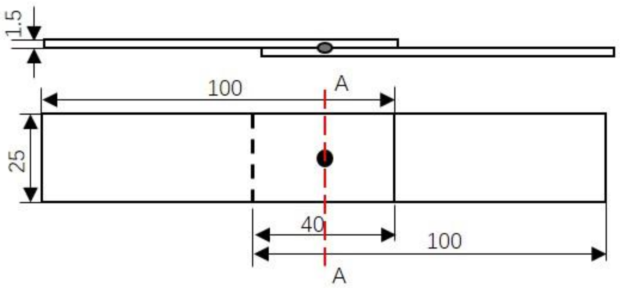
2. Experiment
3. Results and Discussion
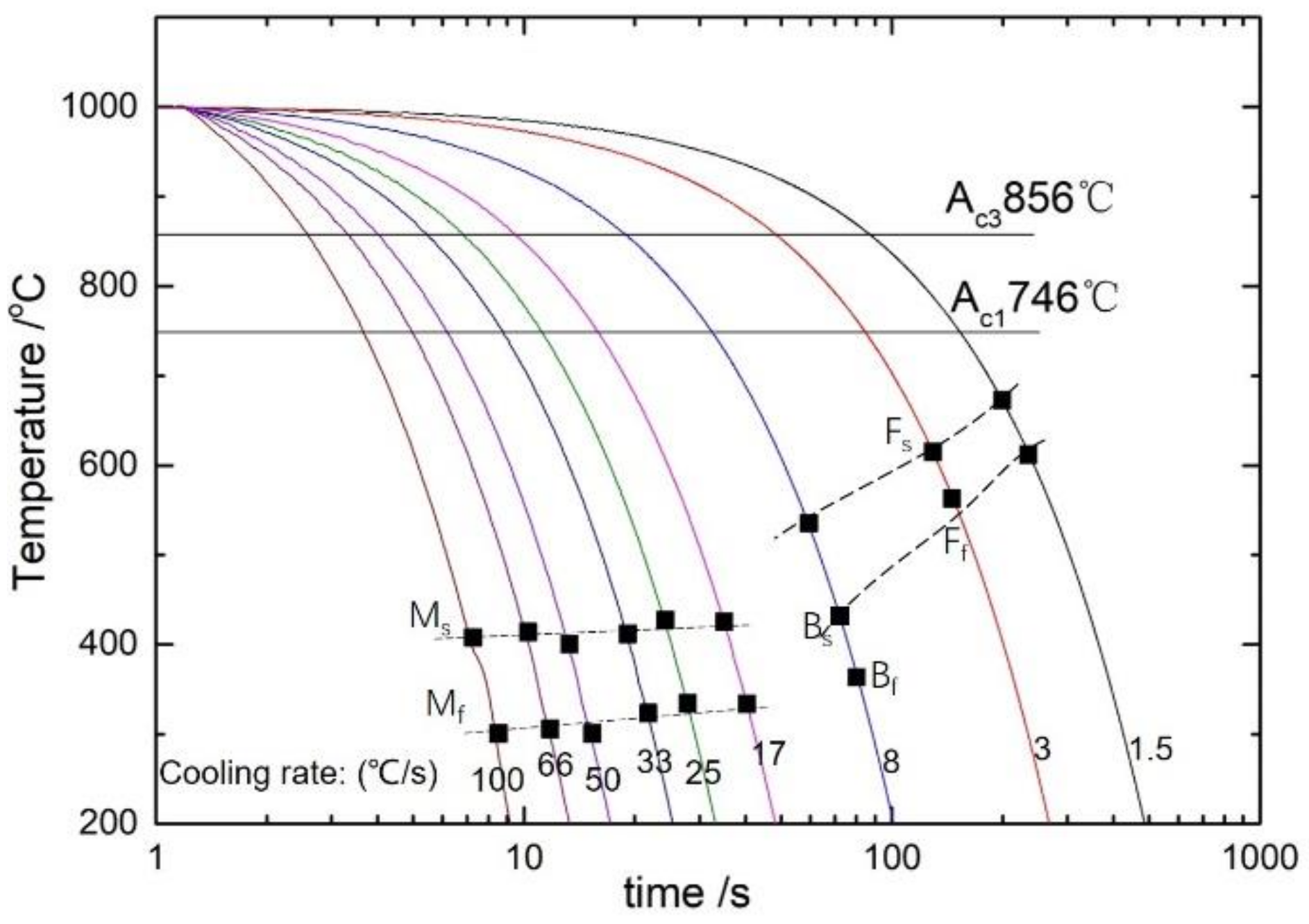
3.1. Continuous Cooling Phase Transformation
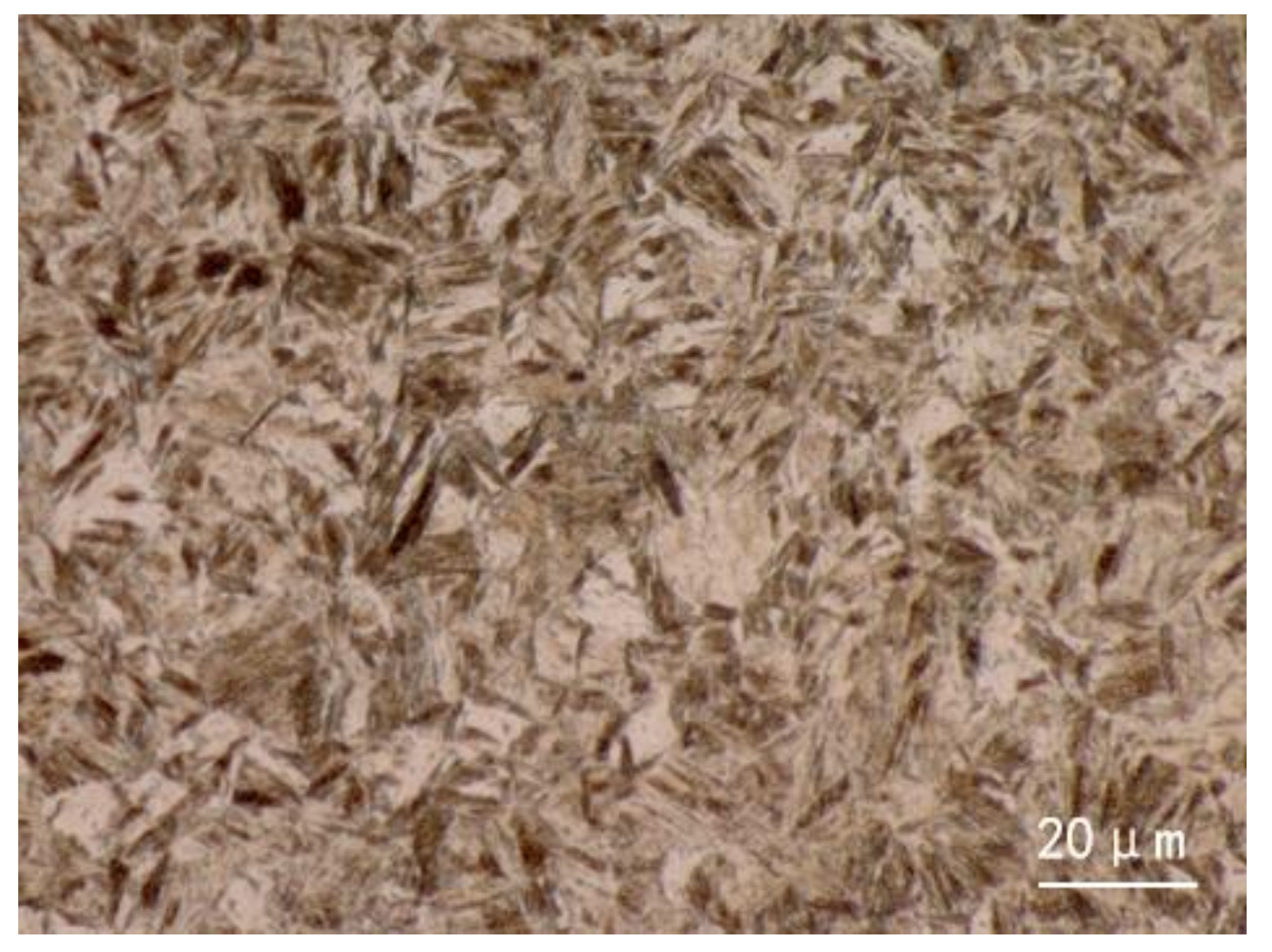
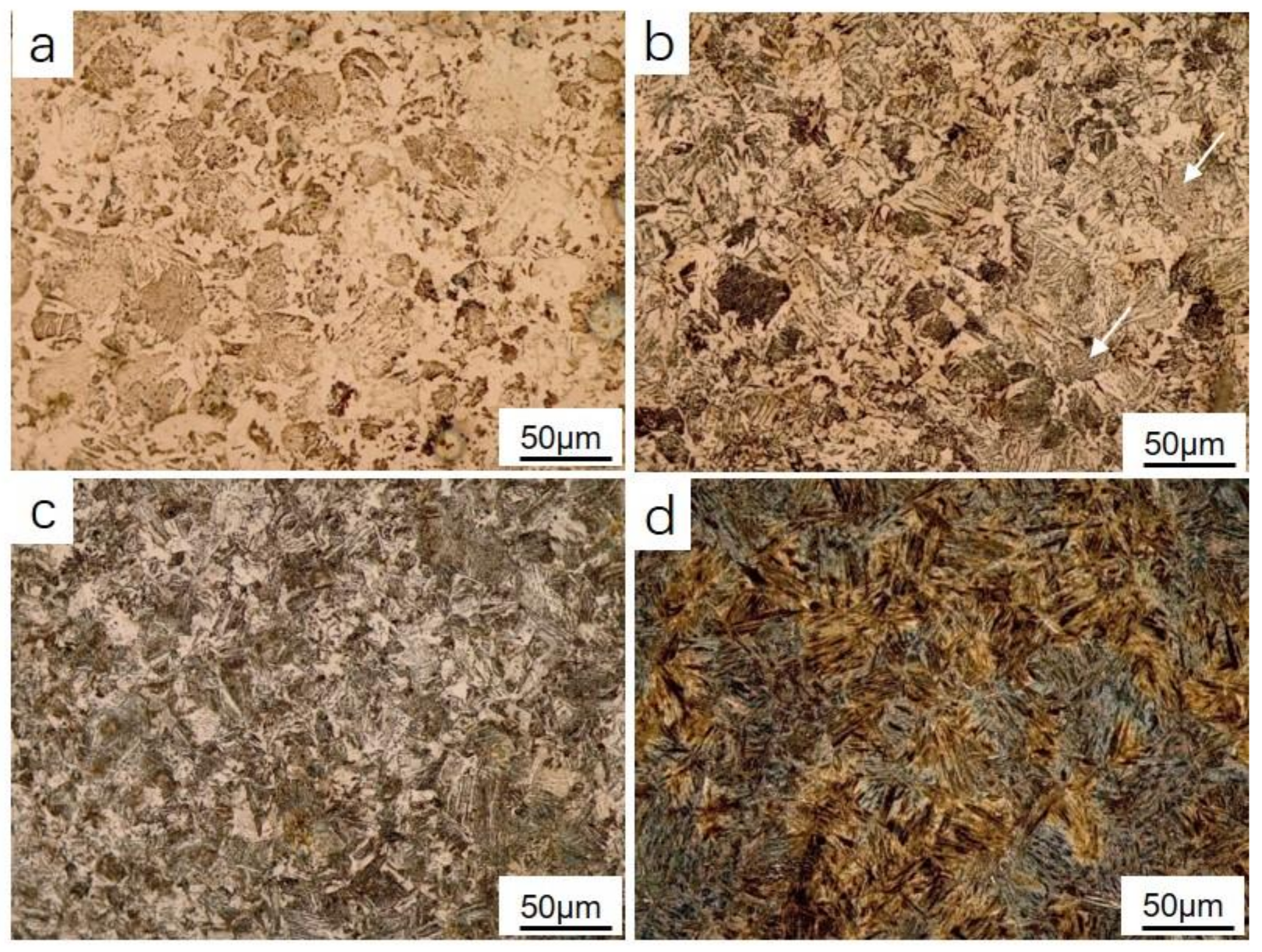
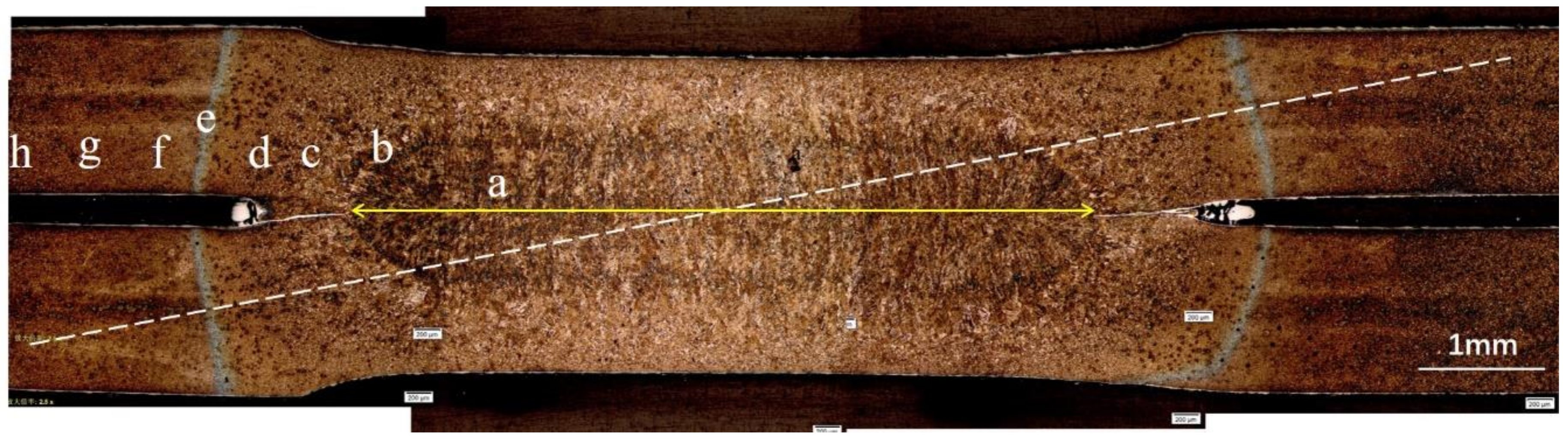
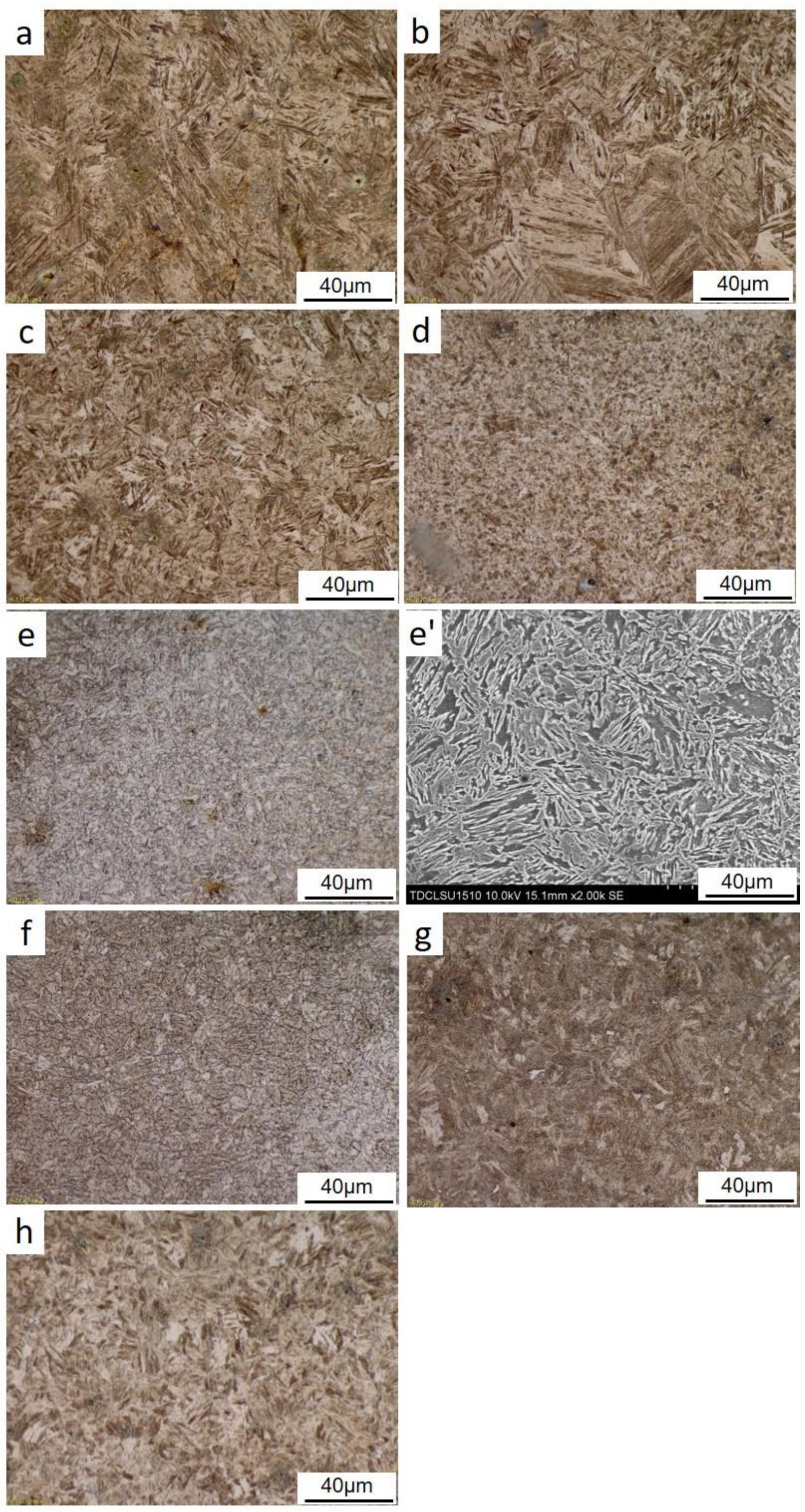
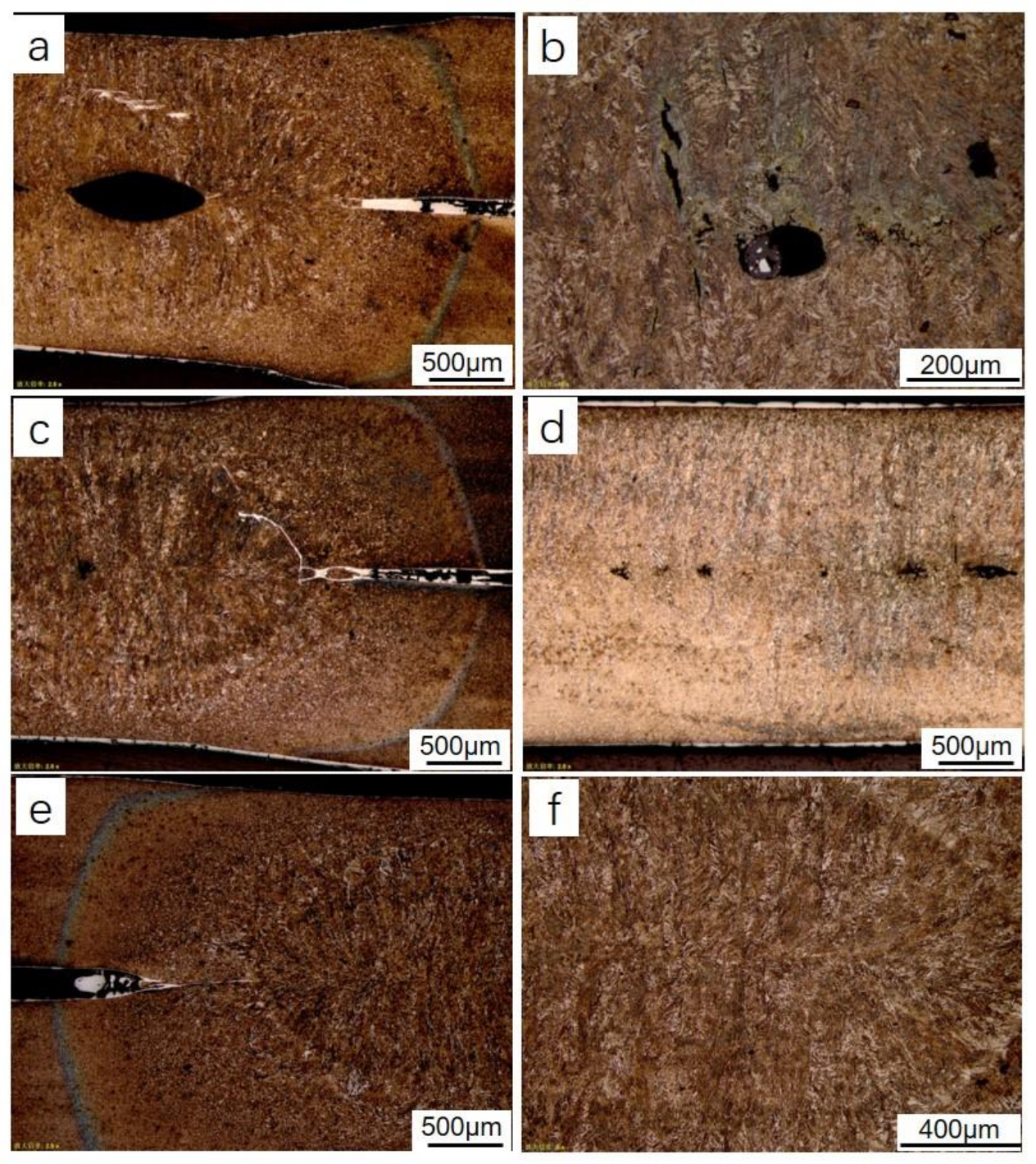
3.2. Microstructures of a Spot Welded Joint
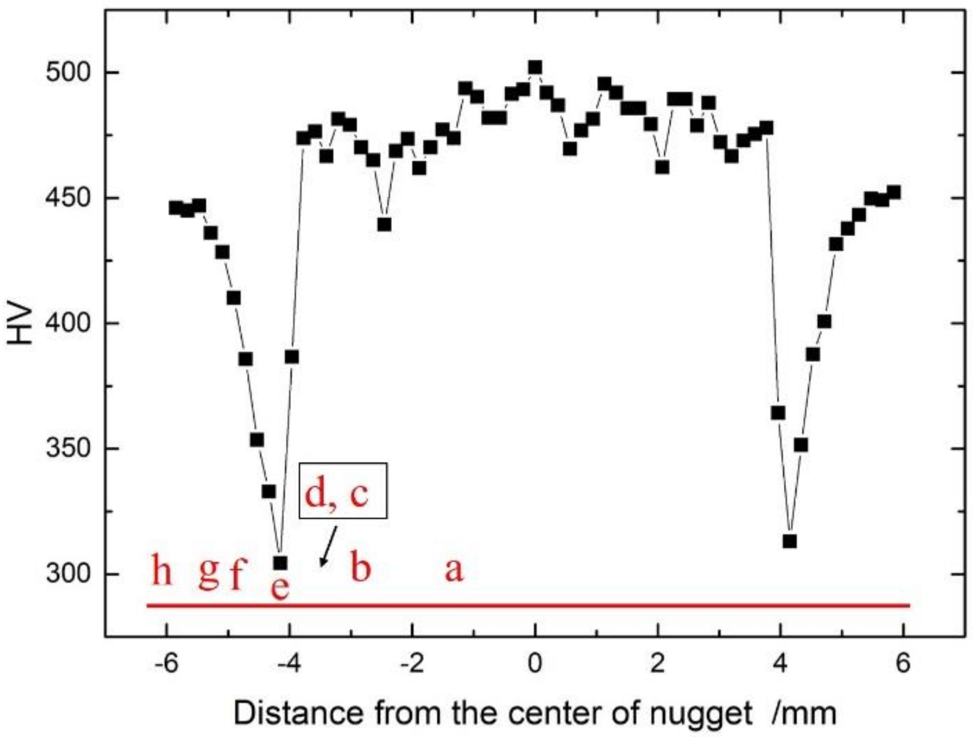
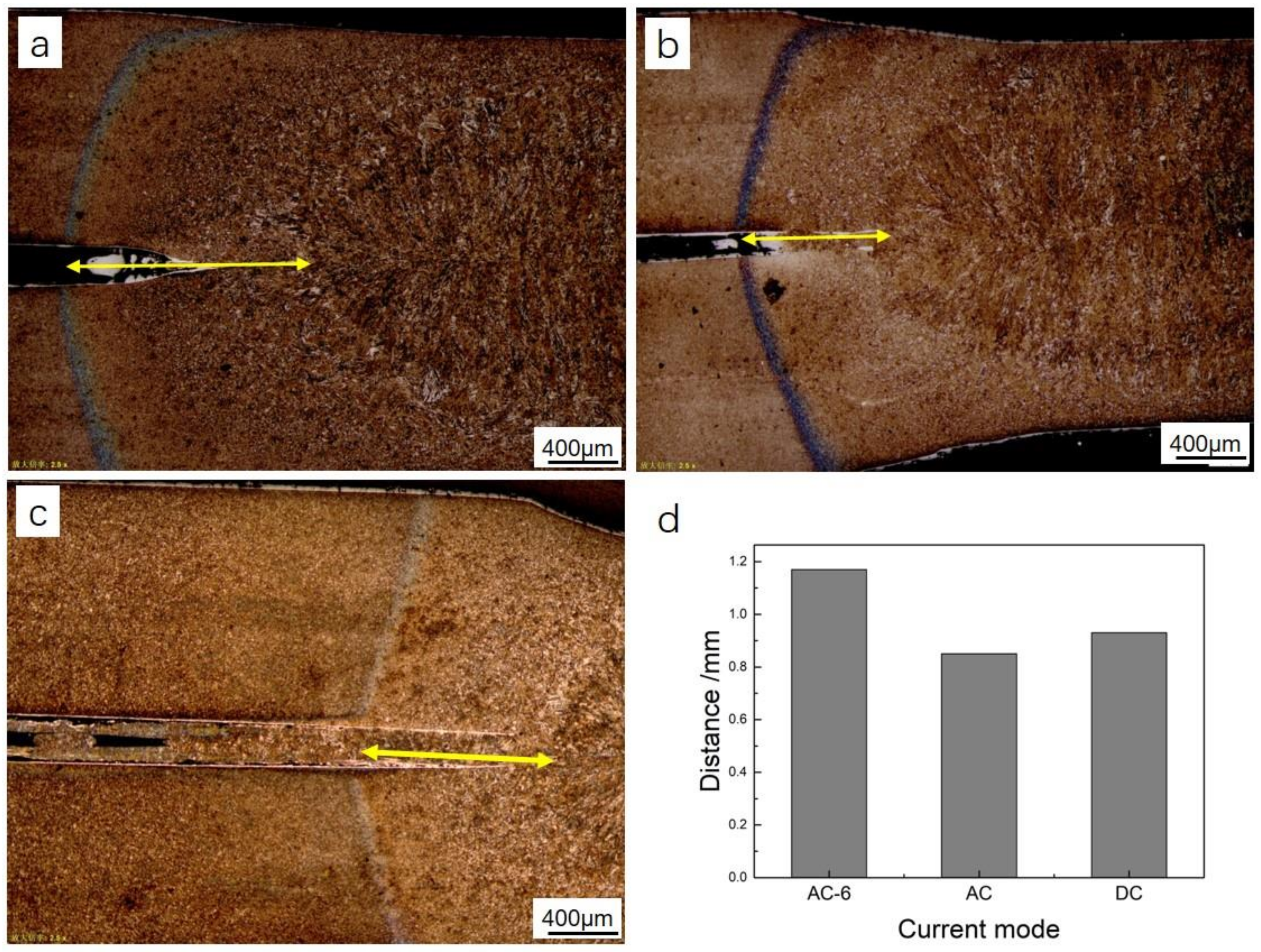
3.3. Micro-Hardness Distribution Across a Spot Welded Joint
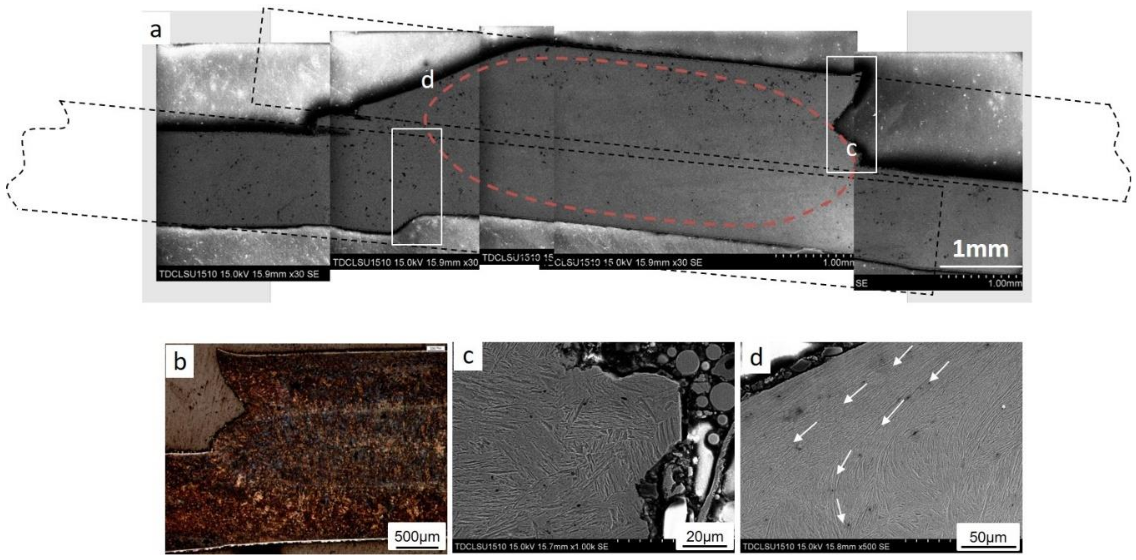
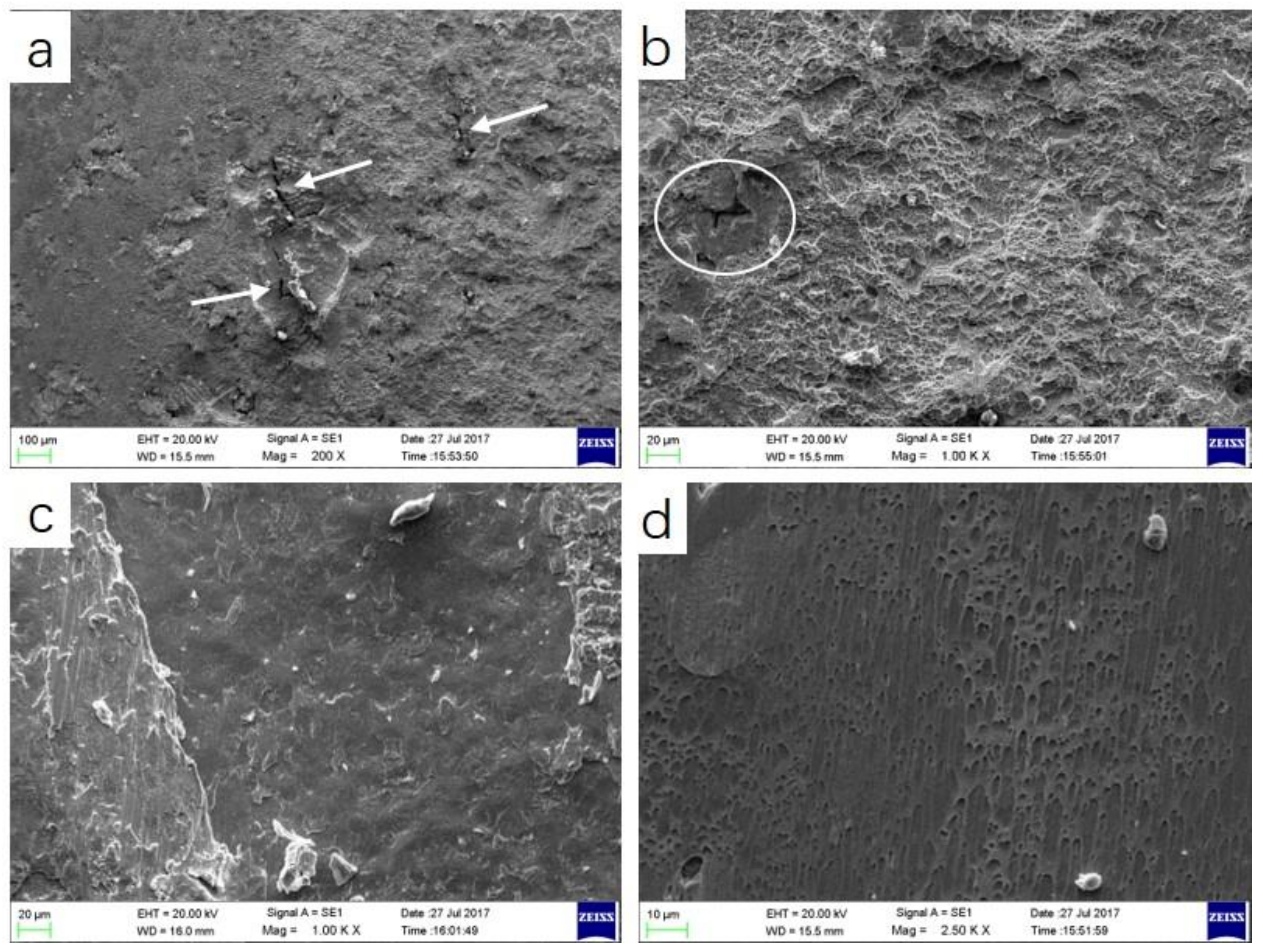
3.4. Tensile Shear Fracture
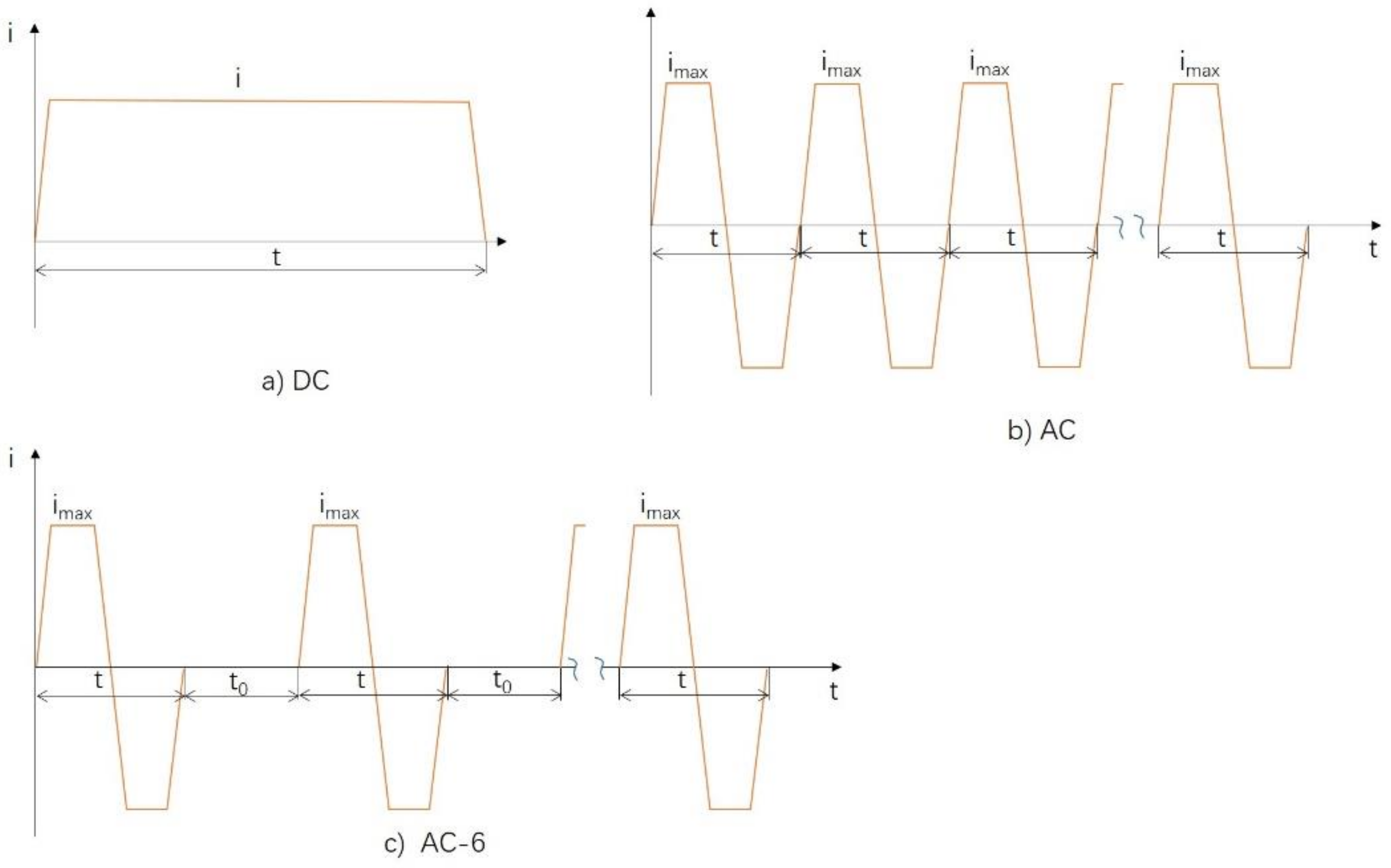
3.5. Parameter Optimization for Spot Welding of Hot-Stamped Hardened Steels
4. Conclusions
Author Contributions
Funding
Conflicts of Interest
References
- Merklein, M.; Wieland, M.; Lechner, M.; Bruschi, S.; Ghiotti, A. Hot stamping of boron steel sheets with tailored properties: A review. J. Mater. Process. Technol. 2016, 228, 11–24. [Google Scholar] [CrossRef]
- Karbasian, H.; Tekkaya, A.E. A review on hot stamping. J. Mater. Process. Technol. 2010, 210, 2103–2118. [Google Scholar] [CrossRef]
- Yi, H.L.; Ghosh, S.; Bhadeshia, H.K.D.H. Dual-phase hot-press forming alloy. Mater. Sci. Eng. A 2010, 527, 4870–4874. [Google Scholar] [CrossRef] [Green Version]
- Ighodaro, O.L.; Biro, E.; Zhou, Y.N. Comparative effects of Al-Si and galvannealed coatings on the properties of resistance spot welded hot stamping steel joints. J. Mater. Process. Technol. 2016, 236, 64–72. [Google Scholar] [CrossRef]
- Jong, Y.-S.; Lee, Y.-K.; Kim, D.-C.; Kang, M.-J.; Hwang, I.-S.; Lee, W.-B. Microstructural Evolution and Mechanical Properties of Resistance Spot Welded Ultra High Strength Steel Containing Boron. Mater. Trans. 2011, 52, 1330–1333. [Google Scholar] [CrossRef] [Green Version]
- Choi, H.-S.; Park, G.-H.; Lim, W.-S.; Kim, B.-M. Evaluation of weldability for resistance spot welded single-lap joint between GA780DP and hot-stamped 22MnB5 steel sheets. J. Mech. Sci. Technol. 2011, 25, 1543. [Google Scholar] [CrossRef]
- Lu, Y.; Peer, A.; Abke, T.; Kimchi, M.; Zhang, W. Subcritical heat affected zone softening in hot-stamped boron steel during resistance spot welding. Mater. Des. 2018, 155, 170–184. [Google Scholar] [CrossRef]
- Ding, L.; Min, H. Simulink and design of mid-frequency inverter resistance spot welding control system. Electr. Weld. Mach. 2015, 45, 26–31. [Google Scholar]
- Brezovnik, R.; Cernelic, J.; Petrun, M.; Dolinar, D.; Ritonja, J. Impact of the switching frequency on the welding current of a spot-welding system. IEEE Trans. Ind. Electron. 2017, 64, 9291–9301. [Google Scholar] [CrossRef]
- Son, J.-I.; Im, Y.-D. Intelligent Controller Implementation for Decreasing Splash in Inverter Spot Welding. IEICE 2009, 92, 1708–1712. [Google Scholar] [CrossRef]
- Yogo, Y.; Kurato, N.; Iwata, N. Investigation of Hardness Change for Spot Welded Tailored Blank in Hot Stamping Using CCT and Deformation-CCT Diagrams. Metall. Mater. Trans. A 2018, 49, 2293–2301. [Google Scholar] [CrossRef]


| C | Si | Mn | Cr | Ni | Mo | V | P | S | B | Fe |
|---|---|---|---|---|---|---|---|---|---|---|
| 0.24 | 0.35 | 1.43 | 0.22 | 0.06 | 0.02 | 0.02 | 0.0317 | 0.0103 | 0.0025 | base |
| Current Mode | imax/kA | Virtual Current/kA | Weld Time/ms | Nugget Diameter/mm | Non-Splash Ratio | Max-Tensile Load/kN |
|---|---|---|---|---|---|---|
| AC-6 | 11 | 6.8 | 377 | 6.2 | 95% | 22 |
| AC | 11 | 9.49 | 182 | 5.5 | 10% | 19 |
| DC | 8.5 | 8.5 | 300 | 5.7 | 10% | 13.5 |
© 2019 by the authors. Licensee MDPI, Basel, Switzerland. This article is an open access article distributed under the terms and conditions of the Creative Commons Attribution (CC BY) license (http://creativecommons.org/licenses/by/4.0/).
Share and Cite
Qiao, Z.; Li, H.; Li, L.; Ran, X.; Feng, L. Microstructure and Properties of Spot Welded Joints of Hot-Stamped Ultra-High Strength Steel Used for Automotive Body Structures. Metals 2019, 9, 285. https://doi.org/10.3390/met9030285
Qiao Z, Li H, Li L, Ran X, Feng L. Microstructure and Properties of Spot Welded Joints of Hot-Stamped Ultra-High Strength Steel Used for Automotive Body Structures. Metals. 2019; 9(3):285. https://doi.org/10.3390/met9030285
Chicago/Turabian StyleQiao, Zhixia, Huijun Li, Lianjin Li, Xiaoyu Ran, and Liwen Feng. 2019. "Microstructure and Properties of Spot Welded Joints of Hot-Stamped Ultra-High Strength Steel Used for Automotive Body Structures" Metals 9, no. 3: 285. https://doi.org/10.3390/met9030285