1. Introduction
The interest in preparing and using Fe–Cu pseudo-alloys started since the 1940s [
1]. One of the potential applications was improving the wear resistance of materials used in tribotechnical devices. The sintered iron–copper alloys were used as electrotechnical material for asynchronous motors since they possessed optimum magnetic permeability and specific electrical resistance [
2]. Consolidated Fe–Cu composites [
3] containing from 2 to 40 mass% Cu had higher mechanical strength as compared to pure iron ones, despite the fact that their tribological behavior was almost similar to that of pure iron composites. The Fe–Cu composites containing more than 10 to 70 mass.% Cu demonstrated improved corrosion resistance and tribological characteristics comparable to those of anti-friction bronzes.
One of the feasible applications for Fe–Cu composites is automotive brake pads and the tests show a stable friction coefficient as well as high durability during tribological tests [
4]. Also, Fe–Cu composites served as the matrix for making multicomponent brake pad materials by filling it with various non-metal additives such as graphite SiO
2, ZrO
2, etc. [
5]. The effect of copper content on tribological characteristics of Fe–C–Cu composites was studied by Dyachkova et al. [
6]. It was shown that friction was reduced for the low-copper composites under constant load and increased for the incrementally increased load.
The effect of adding copper nanosized powders to lubricant oil on friction is known to reduce friction and form an iron-oxide layer on the steel surface [
7]. According to XPES data, copper particles were found in this layer in a metallic form so that the mechanically mixed layer consisted of Fe
2O
3 and metallic copper. More intense mechanical alloying of Cu–Fe powders resulted in formation of FCC Cu(Fe) and BCC Fe(Cu) solid solutions as well as CuO and Cu
2O [
8].
However, tribological behavior of the Fe–Cu matrix has not been fully elucidated. Structural adaptability of materials to friction is determined by their structural as well as mechano-chemical evolution under severe sliding friction conditions. It is especially true for high-temperature sliding friction conditions when tribooxidation becomes very intense and both components may oxidize instead of only iron as it happens at a low sliding speed. Tribooxidation and tribosynthesis of mixed oxides may occur, which is known to be an adaptive mechanism to reduce both wear and friction under high temperature sliding friction [
9]. Practically immiscible metals such as Cu and Fe can form neither alloy nor chemical compound but instead may form mixed oxides known as delafossite CuFeO
2 and cuprospinel CuFe
2O
4.
Bimetallic nanoparticles draw great attention of scientists during past decades “as an emerging new class of materials” that allows not only to combine the characteristic of both dissimilar metals, but also obtain some new unique characteristics [
10]. A great variety of their shapes and structures may be obtained when using different production processes such as electric explosion of wires, mechanical alloying, chemical, and electrochemical methods. Electric explosion of intertwined wires (EEIW) allows producing the oxide-free bimetallic particles and, therefore, it is the preferential method for obtaining electro conductive materials [
11,
12]. It is also a necessary condition for synthesizing the dissimilar immiscible metal bimetallic particles that this method provides a very high cooling rate at the level of ~10
7–10
9 K/s [
13,
14]. An electric explosion of wire (EEW) phenomenon is observed when a 5–15 mm length and 0.1–0.5 mm diameter conducting wire is energized by an electric current with pulse duration 0.5–5.0 μs and density as high as 10
6–10
9 A/cm
2 is thus causing its atomization. Such a process is used to obtain metallic nanoparticles of metals and alloys in either Ar or He atmosphere at 10
5–5 × 10
5 Pa. The explosion product expansion velocity of the buffer gas is at the level of 10
3 m/s [
11].
Improving the mechanical strength of the composites is connected with refining the composite grains by taking advantage of compacting the bimetallic nanoparticles and using a compaction process that allows preserving their size.
When using the bimetallic nanoparticles, which are composed of two dissimilar metals in a singular particle, for obtaining a composite, it is reasonable to employ some dynamic compaction methods in order to avoid grain growth and delamination. Therefore, more homogeneous distribution of components will be provided during compaction. One of the potential methods is the magnetic pulse compaction (MPC), which is based on transformation of an electric energy pulse into a mechanical powder compacting impact [
15,
16,
17,
18,
19]. The impact rise time is about hundreds of microseconds, which provides compaction pressure in the range 1–5 GPa and the powder particle displacement rate in the order of 10–100 m/s. It should be noted that that high velocities, which in fact are several orders of magnitude higher than ~10
−3 to 10
−4 m/s achieved in static pressure compaction, are necessary to prevent the particle coalescence growth. At the same time, the particle velocities achieved during MPC are at least one order of magnitude lower than that of the soundwave in metals so that no shock wave is generated in the compacting powder, which could result in local cracking in the tensile stress regions.
The objective of this work is to study the EEIW Fe–Cu particles, use them for magnetic pulse compacting, and characterize the compacted composites for mechanical strength and high-temperature tribological behavior.
2. Materials and Methods
The bimetallic Fe–Cu powder particles were produced using electric explosion of a twisted pair of dissimilar metal wires in a chamber filled with argon at 3 × 10
5 Pa. More detailed description of the EEIW process is provided elsewhere [
20]. The EEW machine functioning is based on using an RLC-circuit with parameters, as follows:
L ~ 0.75 μH,
C = 3.2 μF,
U0 = 29 kV, where
L- is the inductance,
C is the electric capacity, and
U0 is the charging voltage (
Figure 1). A capacitor battery (C) is charged from the direct current power source (PS) until reaching U
0 voltage level. On reaching the U
o, the air-gap discharger is activated, and the circuit is energized by a current pulse of 10
7 A/cm
2 density. The wires suffer burst atomization into fine drops.
Both wires had the same length of 75 mm and different diameters of ∅0.34 mm (Fe) and ∅0.2 mm (Cu). Their sublimation energies were 418 and 112 J, respectively [
21]. The wire diameter ratio resulted in EEIW producing the powder composed of 73% wt. Fe and 27% wt.Cu.
The time dependencies of the EEIW current
I(
t) and voltage
U(
t) inherent for iron and copper were determined using a TDS2022B oscilloscope (Tektronix Inc., Beaverton, OR, USA) using a scheme shown in our previous paper [
22]. The input energy
E(
t) levels were calculated using Equation (1), as follows:
The
UR(
t) dependence was then obtained using Equation (2);
where
UR(
t) and
UL(
t) are the resistive and inductive components of the voltage drop on an electrical circuit section, which includes the wire, respectively. The inductive one was calculated using Equation (3):
where
Lx is the inductance of the wire-containing circuit, 0.22 μH, and
dI/dt is the EEW current derivative.
The resulting powder was characterized for particle size distribution and particle microstructure using a TEM instrument JEOL JEM-2100 (JEOL Ltd., Akishima, Japan) and X-ray diffractometer XRD-6000(Shimadzu Corp., Kyoto, Japan), CuKα wavelength. Samples for TEM were prepared by dispersing 50 mg powder in 100 mL alcohol and sonication for 5 min in order to provide the powder deagglomeration. Then, a 10 μL portion of the resulting suspension was placed on a carbon-coated ∅3 mm gold mesh substrate and dried.
The powder phase composition was determined using PDF 4+ databases and full-profile analysis software POWDER CELL 2.4 (Federal Institute for Materials Research and Testing, Berlin, Germany).
The particle size distribution was reproduced using the data obtained from sedimentation in a disk centrifuge DC24000 (CPS Instrument Inc., Prairieville, LA, USA). The resulting sonicated for 5 min suspension contained 20 mg particles dispersed in 10 mL alcohol. The duration of analysis was 30 min. The particle size distributions were obtained by counting no less than 4.386 × 10⁹ isolated particles.
The mean particle size (a
s) was determined from measuring the BET specific surface area in a Sorbtometr-M (Catakon Ltd., Novosibirsk, Russia) instrument and formula
where ρ is the density (~8 g/cm
3);
S is the specific surface area, m
2/g.
To produce solid samples, the EEIW bimetallic powders were subjected to magnetic pulse compaction (MPC) at the Institute of Electrophysics UrO RAN, (Yekaterinburg) [
23]. The total amount of powder intended for the compaction was 400 g. A portion of 32 g of powder was loaded into a mold [
23] and then pre-compacted in a static mode until reaching about 40% of the theoretical density. Then, it was degassed at 350 °C and 1 Pa for 4 h prior to magnetic compaction, which was carried out at electric capacity and voltage values 2.2 mF and 4.1 kV, respectively. The MPC parameters such as above have been selected experimentally by achieving the consolidated sample compression strength and density. The compacted sample density was determined using the hydrostatic weighing. On magnetic compaction, the resulting samples were annealed in vacuum at 450 °C for 2 h to relieve the macrostresses induced during compaction. The compacted samples had 5.94 mm height and 30.5 mm diameter.
Microstructural evolution of the compacted samples was examined using an SEM instrument Quanta 200 3D attached with an equipment for ion milling.
Mechanical tests for compression and flexural strength were carried out using an Instron 1195 (Instron, USA) tensile machine at loading rates 50 μm/min and 100 μm/min for flexural and compression tests, respectively. The compression and flexural test samples had their dimensions as follows: 10 mm diameter, 5 mm height and 5 × 5 × 30 mm3, respectively.
Microhardness tester Buehler 1600-6400 (Buehler, Germany) was used to determine the microhardness numbers at 25 g and 50 g loads. At least three samples of each type were tested.
Sliding friction experimenting was carried out using a high-temperature nanotribometer THT-S-BE-0000 (CSM Instruments, Peseux, Switzerland) under test conditions as those shown in
Table 1.
4. Discussion
In distinction to many other methods, the EEW bimetallic Fe–Cu particles were produced using the electric explosion of dissimilar metal wires, i.e., a unique process that allows mixing metals in a liquid state. It is necessary to note that the phase composition of the Fe–Cu particles is sensitive to the EEW process parameters. In contrast to the presented here results, the bimetallic 72 wt.% Fe-28 wt.% Cu nanoparticles were obtained earlier under conditions of a synchronized HV discharge without an arc stage [
35]. It follows from the comparison that increasing the input energy level is accompanied by increasing the content of γ-iron in the resulting powder. According to [
36], the presence of metastable phases in the EEW products is the consequence of a high rate cooling. When EEW is carried out with the arc stage, the cooling rate of nanoparticles must be lower than that of particles obtained under EEW with the arc stage and therefore no γ-iron should have been formed. However, the XRD clearly shows its presence (
Figure 4). In our opinion, such a finding may be explained by extra stabilization of the FCC lattice from Cu atoms, whose solubility in γ-Fe is about 9 wt.% as compared to 0.4 wt.% in α-Fe. The arc stage provides extra heat that allows better intermixing of Cu and Fe atoms in the nanoparticle and thus more homogeneous distribution of Cu in Fe. On cooling, the FCC γ-iron becomes more stabilized.
The role of copper in increasing the content of austenite was reported by Amran et al. [
37]. Another rationale may be that the γ→α transformation is sensitive to the grain size, and nanosized particles acquire extra stabilization at the high-temperature phase [
38].
No residual stresses were induced in the compacted metal. However, compaction resulted in oxidizing the metal especially at the grain boundaries. The majority of the oxides is represented by the iron oxide FeO with lower content of high-temperature cubic spinel CuFe
2O
4. It is known [
39] that among many other methods, MeFe
2O
4 spinels can be obtained via mechanical milling, powder metallurgy, solid state reactions, etc. High local temperatures and pressure are developed during magnetic pulse compaction that serve to the synthesis. It is feasible that a new magnetic pulse process could be developed for fabricating spinels. Cuprospinel CuFe
2O
4 is a widely applied material that has two structural modifications such as cubic and tetragonal ones. Structural transformation from cubic to tetragonal can be facilitated by applied external pressure [
40]. At the same time, the cubic phase is more stable at temperatures above 400 °C.
The MPC samples demonstrated their strength characteristics at the level of those obtained using a cold isostatic pressure compaction of Fe–Cu nanoparticles [
35]. In addition, the MPC sample strength characteristics may be improved by reducing the content of oxides. Their microhardness ~390 ÷ 20 kg/mm
2 is comparable to that of obtained by high-pressure torsion (~ 420 kg/mm
2) [
41]. The high mechanical characteristics of the MPC samples indicate high potential of this compaction method for obtaining multi-functional bulk nanostructured materials
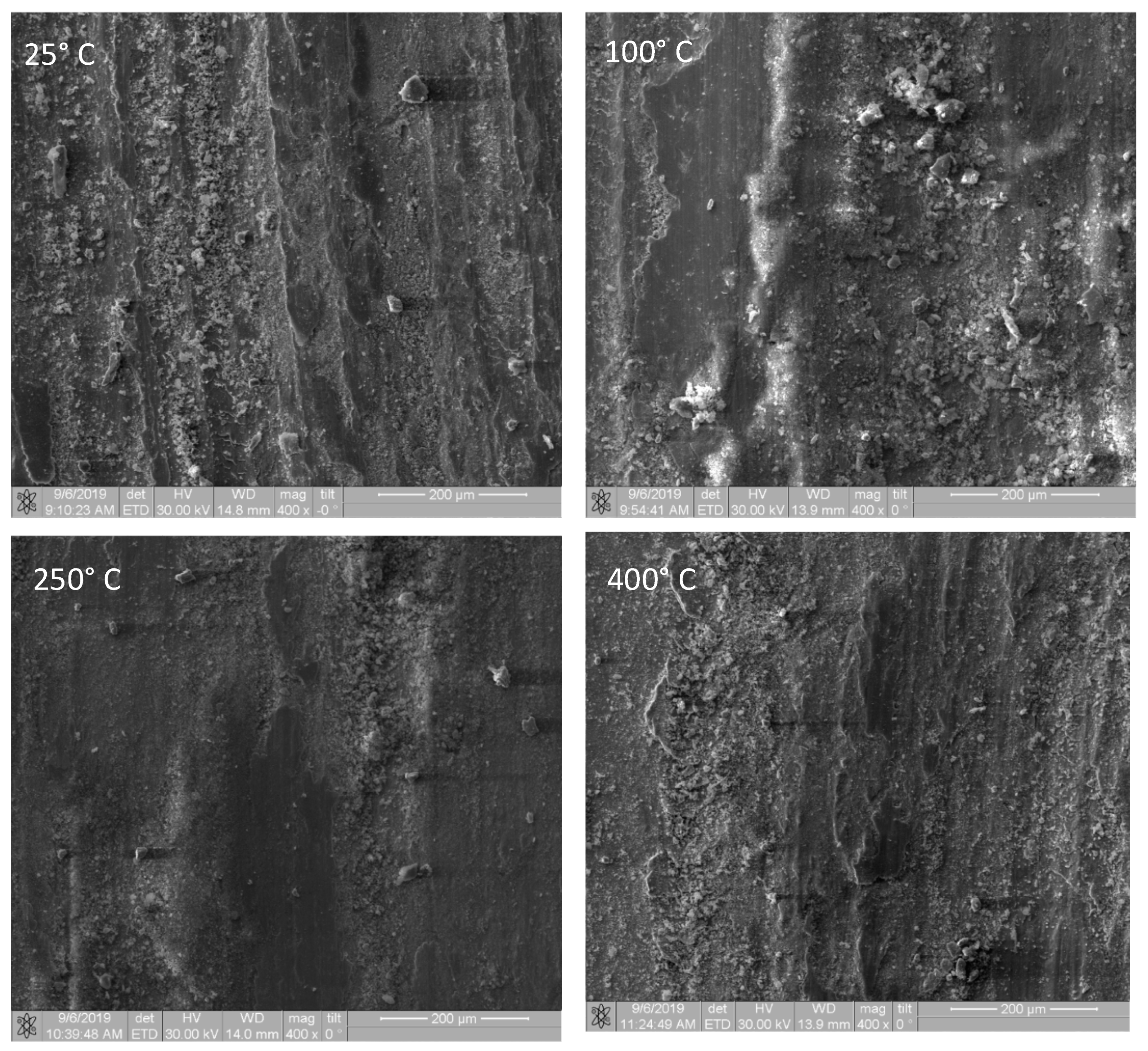
Tribological behavior of the samples shows its temperature dependence. The low-temperature sliding friction test is characterized by low wear. The main wear mechanism is by adhesion and oxidation. Heating the samples to 100 °C resulted in somewhat higher wear of sample and lower wear of the ball. Such a behavior may be explained by thermal softening of the sample while the ball was still hard enough and resisted wear. The maximum wear of both disk and ball was achieved after testing at 250 °C. The wear track on the sample was a deep groove while the ball surface had a hump in the middle. The maximum friction has also corresponded to this temperature.
Further increasing the test temperature led to reducing both friction and wear. Reduction in wear and friction during high-temperature sliding at 400 °C may be provided by mechanochemical formation of extra cuprospinel particles, which were detected using the XRD (
Figure 17). Formation of cuprospinel in fretting wear between Incoloy and technically pure copper was observed by Soria et al. [
42] during characterization of damage and triboparticles resulting from fretting of Incoloy 800 steam generator tubes against different materials.
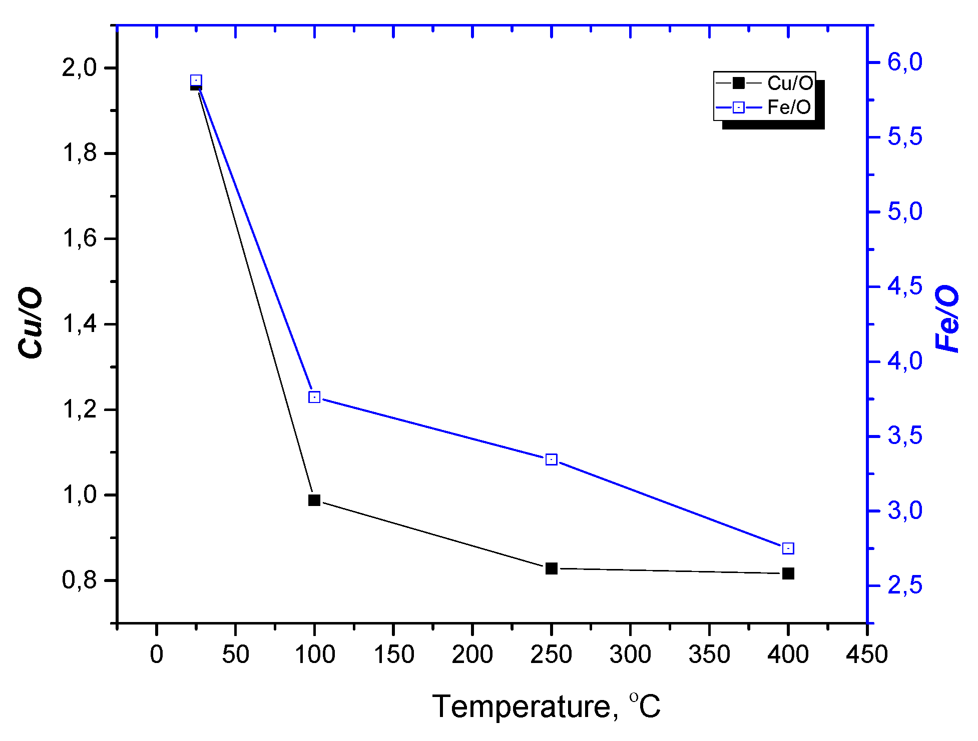
It is understandable that the higher test temperature enhances tribooxidation so that both Cu/O and Fe/O atomic concentration ratios reduce and reach their minimum values after testing at 400 °C.
Author Contributions
A.P., A.K., Y.M., and A.F. performed sample preparation and characterization, A.L., M.L., and S.T. performed conceptualization, designed the experiments, and analyzed the data. A.P. and S.T. wrote this paper.
Funding
Russian Science Foundation (grant No 17-19-01319) funded a part of this work dedicated to bimetallic powder synthesis, compaction and characterization of the samples. Tribological part of work was performed with financial support from Fundamental Research Program of State Academies for 2013–2020, line of research III.23).
Acknowledgments
The authors express their gratitude to S.V. Zayats, a researcher from the applied electrodynamics laboratory at Electrophysics Institute Ural Branch of RAS for his invaluable help in compacting the samples.
Conflicts of Interest
The authors declare no conflict of interest.
References
- Shatsov, A.A. Special features of the structure of metastable steel-copper pseudoalloys. Met. Sci. Heat Treat. 2007, 49, 21–24. [Google Scholar] [CrossRef]
- Anisimova, E.A.; Oleinikov, A.M.; Serdyuk, G.G. Powder materials with specified electrical and magnetic properties for heavy and two-layer rotors of asynchronous motors. Powder Metall. 1990, 9, 87–91. [Google Scholar] [CrossRef]
- Fedorchenko, I.M.; Frantsevich, I.N.; Radomyselsky, I.D.; Kovalchenko, M.S.; Kisly, P.S.; Kosolapova, T.Y.; Mai, V.K.; Scherban, N.I. Powder Metallurgy. Materials, Technology, Characteristics, Applications; Naukova Dumka: Kiev, Ukraine, 1985. [Google Scholar]
- Bratu, V.; Palacios, G.; Nicoleta, I.; Ghit, C. Tribological behaviour and statistical experimental design of sintered iron–copper based composites. Appl. Surf. Sci. 2013, 285, 72–85. [Google Scholar]
- Zhou, H.; Yao, P.; Xiao, Y.; Fan, K.; Zhang, Z.; Gong, T.; Zhao, L.; Deng, M.; Liu, C.; Ling, P. Friction and wear maps of copper metal matrix composites with different iron volume content. Trib. Int. 2019, 132, 199–210. [Google Scholar] [CrossRef]
- Dyachkova, L.N.; Feldshtein, E.E.; Vityaz, P.A.; Błoch, B.M.; Voronetskaya, L.Y. Effect of Copper Content on Tribological Characteristics of Fe−C−Cu Composites. J. Frict. Wear 2018, 39, 5–10. [Google Scholar] [CrossRef]
- Tarasov, S.; Belyaev, S. Alloying contact zones by metallic nanopowders in sliding wear. Wear 2004, 257, 523–530. [Google Scholar] [CrossRef]
- Azabou, M.; Gharsallah, H.I.; Escoda, L.; Suñol, J.J.; Kolsi, A.W.; Khitouni, M. Mechanochemical reactions in nanocrystalline Cu–Fe system induced by mechanical alloying in air atmosphere. Powder Technol. 2012, 224, 338–344. [Google Scholar] [CrossRef]
- Voevodin, A.A.; Muratore, C.; Aouadi, S.M. Hard coatings with high temperature adaptive lubrication and contact thermal management: Review. Surf. Coat. Technol. 2014, 257, 247–265. [Google Scholar] [CrossRef]
- Liu, W.-J.; Qian, T.-T.; Jiang, H. Bimetallic Fe nanoparticles: Recent advances in synthesis and application in catalytic elimination of environmental pollutants. Chem. Eng. J. 2014, 236, 448–463. [Google Scholar] [CrossRef]
- Romanova, V.M.; Ivanenkov, G.V.; Mingaleev, A.R.; Ter-Oganesyan, A.E.; Shelkovenko, T.A.; Pikuz, S.A. Electric explosion of fine wires: Three groups of materials. Plasma Phys. Rep. 2015, 41, 617–636. [Google Scholar] [CrossRef]
- Pervikov, A.; Lozhkomoev, A.; Bakina, O.; Lerner, M. Synthesis of core-shell and Janus-like nanoparticles by non-synchronous electrical explosion of two intertwined wires from immiscible metals. Sol. Stat. Sci. 2019, 87, 146–149. [Google Scholar] [CrossRef]
- Sindhu, T.K.; Sarathi, R.; Chakravarthy, S.R. Understanding nanoparticle formation by a wire explosion process through experimental and modelling studies. Nanotechnology 2008, 19, 025703. [Google Scholar] [CrossRef] [PubMed]
- Grigorieva, T.; Barinova, A.; Lyakhov, N. Mechanochemical synthesis of intermetallic compounds. Russ. Chem. Rev. 2001, 70, 45–63. [Google Scholar] [CrossRef]
- Ivanov, V.; Kotov, Y.A.; Samatov, O.H.; Böhme, R.; Karow, H.U.; Schumacher, G. Synthesis and dynamic compaction of ceramic nano powders by techniques based on electric pulsed power. Nanostr. Mater. 1995, 6, 287–290. [Google Scholar] [CrossRef]
- Park, H.-Y.; Kilicaslan, M.F.; Hong, S.-J. Densification behaviour analysis of ZrO2 nanopowders for dental applications compacted by magnetic pulsed compaction. Mater. Chem. Phys. 2013, 141, 208–215. [Google Scholar] [CrossRef]
- Lee, G.H.; Rhee, C.K.; Lee, M.K.; Kim, W.W.; Ivanov, V.V. Nanostructures and mechanical properties of copper compacts prepared by magnetic pulsed compaction method. Mat. Sci. Eng. A 2004, 375, 604–608. [Google Scholar] [CrossRef]
- Yan, S.; Huang, S.; Liu, W.; Hu, J.; Lei, Y.; Zhou, M. Experimental and numerical investigation of temperature evolution during electromagnetic pulsed compaction of powders. Powder Technol. 2017, 306, 1–9. [Google Scholar] [CrossRef]
- Shin, D.-W.; Kim, D.-S.; Madavali, B.; Kim, D.-H.; Kim, J.-G.; Lee, C.-H.; Challapalli, S.; Hong, S.-J. Densification mechanism and its effect on the magnetic properties of Nd-Fe-B bonded magnets through the new high-energy compaction method. J. Magn. Magn. Mater. 2019, 482, 280–286. [Google Scholar] [CrossRef]
- Lerner, M.; Pervikov, A.; Glazkova, E.; Svarovskaya, N.; Lozhkomoev, A.; Psakhie, S. Structures of binary metallic nanoparticles produced by electrical explosion of two wires from immiscible elements. Powder Technol. 2016, 288, 371–378. [Google Scholar] [CrossRef]
- Haynes, W.M. CRC Handbook of Chemistry and Physics, 97th ed.; CRC Press: Boca Raton, FL, USA, 2017; p. 2643. [Google Scholar]
- Pervikov, A.; Glazkova, E.; Lerner, M. Energy characteristics of the electrical explosion of two intertwined wires made of dissimilar metals. Phys. Plasmas 2018, 25, 070701. [Google Scholar] [CrossRef]
- Bokov, A.; Boltachev, G.; Volkov, N.; Zayats, S.; Il’ina, A.; Nozdrin, A.; Paranin, S.; Olevskii, E. Uniaxial compaction of nanopowders on a magnetic-pulse press. Tech. Phys. 2013, 58, 1459–1468. [Google Scholar] [CrossRef]
- Bora, B.; Kausik, S.S.; Wong, C.S.; Chin, O.H.; Yap, S.L.; Soto, L. Observation of the partial reheating of the metallic vapor during the wire explosion process for nanoparticle synthesis. Appl. Phys. Lett. 2014, 104, 223108. [Google Scholar] [CrossRef]
- Lerner, M.I.; Glazkova, E.A.; Lozhkomoev, A.S.; Bakina, O.V.; Psakhie, S.G.; Svarovskaya, N.V.; Pervikov, A.V. Synthesis of Al nanoparticles and Al/AlN composite nanoparticles by electrical explosion of aluminum wires in argon and nitrogen. Powder Technol. 2016, 295, 307–314. [Google Scholar] [CrossRef]
- Bai, J.; Shi, Z.; Jia, S. Numerical investigation on the growth process and size distribution of nanoparticles obtained through electrical explosion of aluminum wire. J. Phys. D Appl. Phys. 2017, 50, 075301. [Google Scholar] [CrossRef]
- Shi, H.; Wu, J.; Li, X.; Murphy, A.B.; Li, X.; Li, C.; Li, P. Understanding the nanoparticle formation during electrical wire explosion using a modified moment model. Plasma Sources Sci. Technol. 2019, 28, 085010. [Google Scholar] [CrossRef]
- Lv, F.; Liu, P.; Qi, H.; Liu, J.; Sun, R.; Wang, W. The early stage of the thermal pulse explosions of aluminum nanowires under different energy deposition levels. Comput. Mater. Sci. 2019, 170, 109142. [Google Scholar] [CrossRef]
- Lebedev, S.V.; Savvatimskii, A.I. Metals during rapid heating by dense currents. Sov. Phys. Usp. 1984, 27, 749–771. [Google Scholar] [CrossRef]
- Volkov, N.B.; Mayer, A.E.; Sedoi, V.S.; Fen’ko, E.L.; Yalovets, A.P. Mechanisms of metallic nanoparticle generation during an electric explosion of conductors. Tech. Phys. 2010, 55, 509–513. [Google Scholar] [CrossRef]
- Baksht, R.B.; Oreshkin, V.I.; Tkachenko, S.I.; Khattatov, T.A.; Romanova, V.M.; Mingaleev, A.R.; Ter-Oganesyan, A.E.; Shelkovenko, T.A.; Pikuz, S.A. Stratification dynamics and the development of electrothermal instability at the wire explosion. Tech. Phys. 2013, 58, 1129–1137. [Google Scholar] [CrossRef]
- Walther, A.; Müller, A.H.E. Janus particles: Synthesis, self-assembly, physical properties, and applications. Chem. Rev. 2013, 113, 5194–5261. [Google Scholar] [CrossRef]
- Sarkisov, G.; Sasorov, P.; Struve, K.; McDaniel, D. State of the metal core in nanosecond exploding wires and related phenomena. J. Appl. Phys. 2004, 96, 1674–1686. [Google Scholar] [CrossRef]
- Han, R.; Wu, J.; Zhou, H.; Ding, W.; Qiu, A.; Clayson, T.; Wang, J.; Ren, H. Characteristics of exploding metal wires in water with three discharge types. J. Appl. Phys. 2017, 122, 033302. [Google Scholar] [CrossRef]
- Lerner, M.I.; Psakhie, S.G.; Lozhkomoev, A.S.; Sharipova, A.F.; Pervikov, A.V.; Gotman, I.; Gutmanas, E.Y. Fe-Cu Nanocomposites by high pressure consolidation of powders prepared by electric explosion of wires. Adv. Eng. Mater. 2018, 20, 1701024. [Google Scholar] [CrossRef]
- Kotov, Y.A. The electrical explosion of wire: A method for the synthesis of weakly aggregated nanopowders. Nanotechnol. Russ. 2009, 4, 415–424. [Google Scholar] [CrossRef]
- Amran, Y.; Katsman, A.; Shaaf, P.; Bamberger, M. Influence of copper addition and temperature on the kinetics of austempering in ductile iron. Met. Mater. Trans. B 2010, 41, 1052–1058. [Google Scholar] [CrossRef] [Green Version]
- Morokhov, I.D.; Petinov, V.I.; Trusov, L.I.; Petrunin, V.F. Structure and properties of fine metallic particles. Sov. Phys. Usp. 1981, 24, 295–317. [Google Scholar] [CrossRef]
- Tatarchuk, T.; Bououdina, M.; Vijaya, J.J.; Kennedy, L.J. Spinel Ferrite Nanoparticles: Synthesis, Crystal Structure, Properties, and Perspective Applications. In Nanophysics, Nanomaterials, Interface Studies, and Applications; Springer International Publishing AG: Cham, Switzerland, 2017; Chapter 22; pp. 305–321. [Google Scholar]
- Kyono, A.; Gramsch, S.A.; Nakamoto, Y.; Sakata, M.; Kato, M.; Tamura, T.; Yamanaka, T. High-pressure behavior of cuprospinel CuFe2O4: Influence of the Jahn-Teller effect on the spinel structure. Am. Mineral. 2015, 100, 752–1761. [Google Scholar] [CrossRef]
- Bachmaier, A.; Kerber, M.; Setman, D.; Pippan, R. The formation of supersaturated solid solutions in Fe–Cu alloys deformed by high-pressure torsion. Acta Mat. 2012, 60, 860–871. [Google Scholar] [CrossRef] [Green Version]
- Soria, S.R.; Balbiani, J.P.; Bergant, M.; Tolley, A.; Yawny, A. Fretting damage in Incoloy® 800 tubes against different support materials. Proc. Mater. Sci. 2015, 9, 538–547. [Google Scholar] [CrossRef] [Green Version]
Figure 1.
Circuit diagram of the machine employed for the production of Fe–Cu nanoparticles.
Figure 2.
The EEIW current I(t), voltage U(t) and input energy E(t) during double-wire explosion.
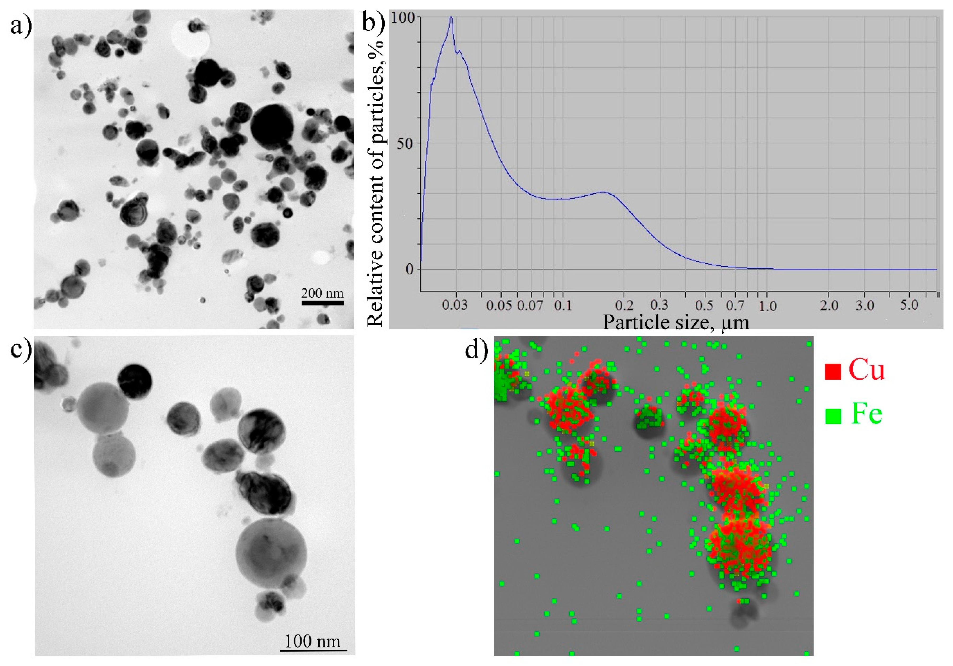
Figure 3.
TEM images of the bimetallic EEIW Fe–Cu particles (
a,c), particle size distribution (
b), (
d) the EDS Fe–Cu map of the particles shown in
Figure 3c.
Figure 4.
The SEM image of the as-synthesized Fe–Cu micron-sized particles.
Figure 5.
The XRD pattern of the as-synthesized Fe–Cu powder.
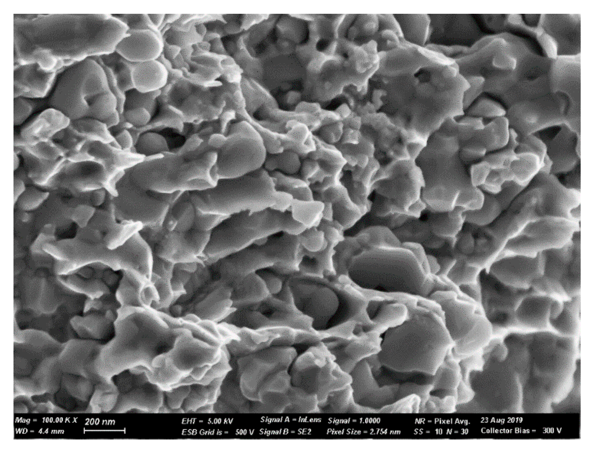
Figure 6.
Microstructure of a magnetic pulse compacted sample.
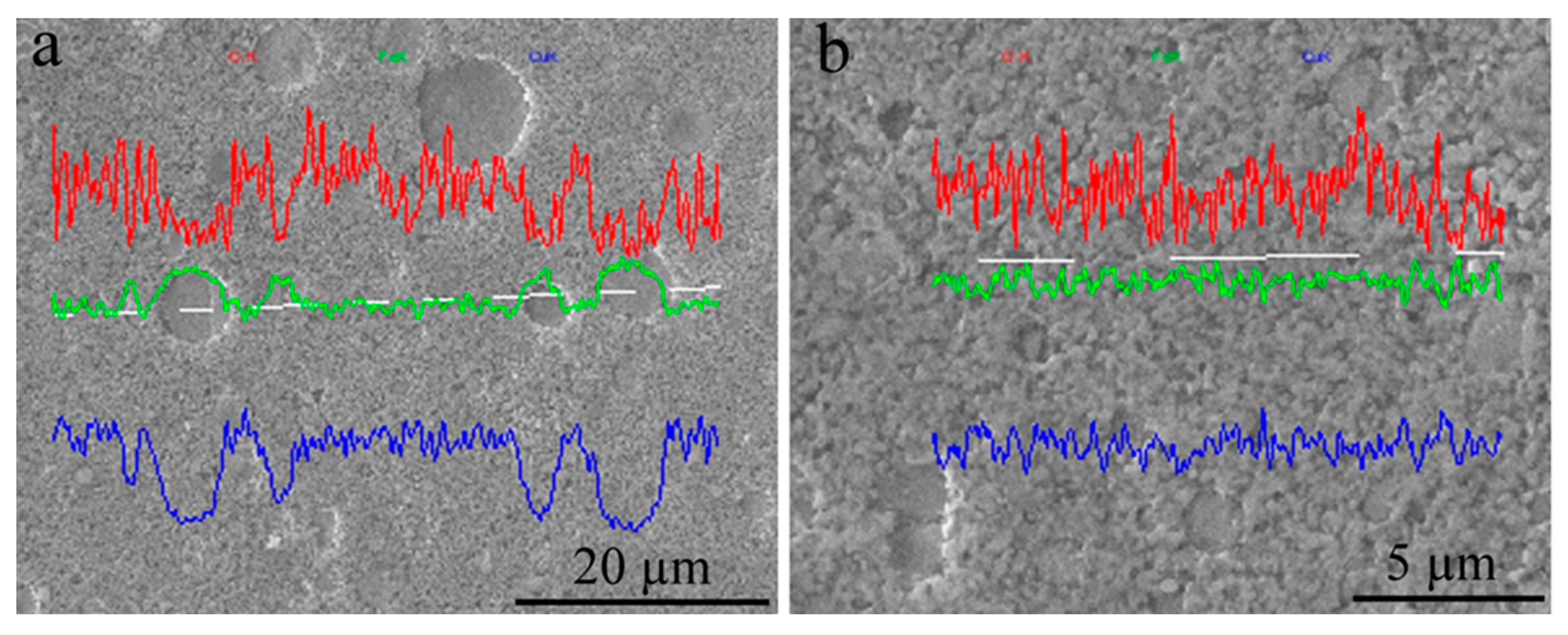
Figure 7.
The SEM images of as-compacted samples with the imposed EDS profiles of oxygen (red line), iron (green line), and copper (blue line) showing large iron particles (a) and fine copper/iron crystallite mixture (b).
Figure 8.
The XRD pattern of as-compacted samples.
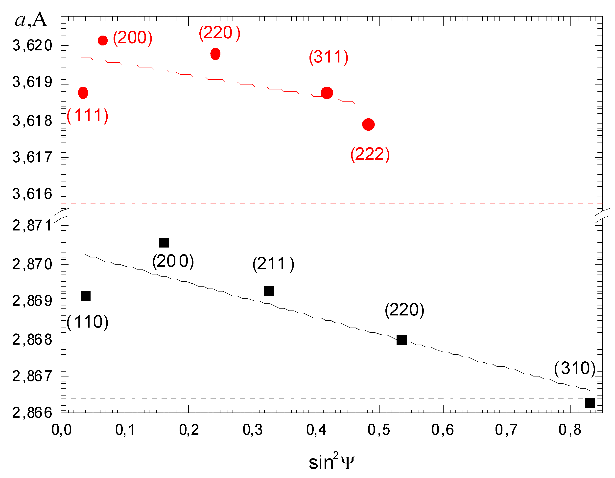
Figure 9.
Approximation lines for lattice parameters of Cu (red line) and Fe (black line) as measured from an asymmetrical scheme according to the sin2ψ method. The dotted lines show corresponding lattice parameter values obtained from a symmetrical scheme.
Figure 10.
Flexural (a) and compression (b) stress–strain diagrams for as-compacted samples.
Figure 11.
SEM micrograph of as-compacted and annealed sample flexural test fracture surface.
Figure 12.
Tribological parameters such as friction coefficient (f), disk sample wear (Wdisk), and the ball wear (Wball) vs. the test temperature.
Figure 13.
Cross section areas of wear grooves formed on the sample disks in sliding friction by steel balls at different temperatures.
Figure 14.
The wear spot surface profiles on the steel balls.
Figure 15.
The SEM images of wear track surfaces on samples tested at: (a) 25 °C, (b) 100 °C, (c) 250 °C, (d) 400 °C.
Figure 16.
Copper/oxygen and iron/oxygen atomic concentration ratios on the wear track metal depending on the test temperature.
Figure 17.
XRD diagrams of the wear track surface of samples tested at different temperatures.
Figure 18.
The remainder XRD plots showing the difference between the worn surface phase composition and that of the sample back side.
Table 1.
Pin-on-disk tribology testing.
| № | Temperature,
°C | Rotation Rate,
RPM | Radius,
mm | Time,
s | Linear Speed,
m/s | Normal Load,
N |
|---|
| 1 | 25 | 300 | 8 | 3600 | 0.25 | 10 |
| 2 | 100 | 300 | 8 | 3600 | 0.25 | 10 |
| 3 | 250 | 300 | 8 | 3600 | 0.25 | 6 |
| 4 | 400 | 300 | 8 | 3600 | 0.25 | 5 |
Table 2.
Phase composition of the wear track subsurface metal.
| Test Temperature | | Phase Content, wt.% |
|---|
| a-Fe | Cu | CuFe2O4 | FeO | Fe2O3 |
|---|
| Consolidated sample | 58.2 | 37.2 | 2.9 | 1.7 | — |
| 25 | 61.3 | 34.4 | 4.3 | — | — |
| 100 | 60.7 | 35.0 | 4.2 | — | — |
| 250 | 59.5 | 31.0 | 6.6 | — | 2.9 |
| 400 | 58.0 | 31.7 | 8.0 | — | 2.3 |
© 2019 by the authors. Licensee MDPI, Basel, Switzerland. This article is an open access article distributed under the terms and conditions of the Creative Commons Attribution (CC BY) license (http://creativecommons.org/licenses/by/4.0/).

 ,
, 


