Review

Review: The Impact of Metal Additive Manufacturing on the Aerospace Industry

Materials Research Group, Faculty of Engineering and Physical Sciences, University of Southampton, Southampton SO17 1BJ, UK
*
Author to whom correspondence should be addressed.
Metals 2019, 9(12), 1286; https://doi.org/10.3390/met9121286
Submission received: 28 October 2019 / Revised: 18 November 2019 / Accepted: 27 November 2019 / Published: 29 November 2019
(This article belongs to the Special Issue Additive Manufacturing of Metals with Lasers)

Abstract

:
Metal additive manufacturing (AM) has matured from its infancy in the research stage to the fabrication of a wide range of commercial functional applications. In particular, at present, metal AM is now popular in the aerospace industry to build and repair various components for commercial and military aircraft, as well as outer space vehicles. Firstly, this review describes the categories of AM technologies that are commonly used to fabricate metallic parts. Then, the evolution of metal AM used in the aerospace industry from just prototyping to the manufacturing of propulsion systems and structural components is also highlighted. In addition, current outstanding issues that prevent metal AM from entering mass production in the aerospace industry are discussed, including the development of standards and qualifications, sustainability, and supply chain development.

1. Introduction

The elementary concept of additively manufacturing a product has existed for decades. It is defined as the process of incrementally creating objects from computer model data, layer by layer, until a three-dimensional object is built [1,2]. The first attempts to additively manufacture objects originated in the American-based Battelle Memorial Institute in the late 1960s [3], where researchers used the interactions of laser beams and photopolymers to create solid objects in a resin vat [4]. Emerging in a viable commercial form in 1987 as stereolithography (SLA) under the patent holder Charles Hull, its introduction to the marketplace was developed with other technologies such as fused deposition modeling (FDM), selective laser sintering (SLS), and inkjet printing, all of which are still utilized today [5].
The early applications of additive manufacturing (AM) technology include the rapid prototyping (RP) of machine tools and RP to support continuous product development by providing prototype models for physical product validation. However, over the last decade, AM has seen swift advancements in technological capability and has been increasingly used as a form of direct manufacturing. In niche industries such as the aerospace, biomedical, and automotive industries, AM is now used hand in hand with conventional manufacturing (CM), e.g., subtractive manufacturing (SM), which relies on the removal of material to produce an end product [6]. This has subsequently resulted in an upsurge of start-up companies for the rapid manufacturing (RM) of components [7,8].
In the aerospace industry, AM is specifically experiencing a continuingly upward trend of utilization in the fabrication of various individual aircraft components which accounted for 16.6% and 18.2% of the global industry market share in 2016 and 2017, respectively [9,10]. One of the major reasons for this is the prospect of redesigning and manufacturing parts on demand with significant mass and cost reduction, without sacrificing the mechanical properties of the AM-fabricated components. A key feature of fusion-based AM technologies used to fabricate aerospace components is their rapid melting/solidification cycles that lead to high cooling rates, which result in very fine grains that yield comparable, if not improved mechanical properties compared to CM parts [11,12,13,14,15]. In addition, the flexibility of these fusion-based AM technologies allows for microstructural features such as grain structure, texture, and topology to be controlled via manipulation of process parameters during the fabrication stage [16]. Such flexibility not only permits the creation of complex features that are otherwise difficult to be machined or manufactured by CM processes but also enables the tailoring of microstructures, which are of critical importance to the building of high-performance aerospace components since they often operate in complex environments, e.g. elevated temperatures, harsh weather, and prolonged lifespans [17]. Furthermore, the economics of AM processes heavily favor the low-volume production of the aerospace industry. A large contributor to the high production cost associated with aerospace components via conventional SM processes is related to their high buy-to-fly ratio, defined as the mass ratio between the input material and the final product. For the aerospace industry, in particular, this ratio fluctuates between 10:1 and 15–20:1, and can be as high as 40:1 for increasingly complex components [10,18]. Since AM offers the advantage of producing near net-shaped products, the buy-to-fly ratio can be considerably reduced and even close to 1:1 [7]. With improvement of internal microstructures, higher input-material utilization and less associated material wastage, and faster processing time, AM technology is now no longer viewed as merely a prototyping option but as a direct manufacturing method which can produce near net-shaped products with high quality [7]. This new AM technology provides increased control for end-users and in particular for component specifications such as mass, geometric constraints, and incurred costs [19]. Furthermore, the successful adaptation of metal AM in the aerospace sector provides more opportunities in terms of sustainability and associated supply chain structures in the future.
However, while AM is experiencing rapid successful adoption in the aerospace, automotive, and medical fields, AM is still considered a developing technology. With regard to the lack of established associated standards and certification for AM-produced components, the majority of current AM usage has been restricted to non-mission critical applications within the aerospace industry [20]. To address these issues, manufacturers and regulatory aviation bodies are increasingly working towards the development of new standards to meet the current capabilities of AM [21]. Moreover, it should be noted that both academic institutions and commercial companies have established their own classifications of AM technologies due to the lack of such unified standards, which has often resulted in confusing and contradictory categorization of AM processes and nomenclatures [22]. So far, a number of standards regarding metal AM in general have been developed; standards include the ISO/ASTM52900-15 regarding standard AM terminology, the ASTM F3122-14 regarding the evaluation of mechanical properties of metal AM parts, and the ASTM F3049-14 regarding the characterization of metal powders used for AM processes [1,23]. However, only a few standards and qualifications have been established in the context of the application of metal AM within the aerospace industry; examples include the MSFC-STD-3716 regarding spaceflight hardware fabricated by laser powder bed fusion (L-PBF) metal AM processes and SAE AS9100 regarding the requirements for quality management systems in aviation, space, and defense organizations [1,23]. Significant efforts are therefore still required to fully integrate the standards for metal AM and specifically to meet the requirements of aerospace applications, which are currently pioneered by the National Aeronautics and Space Administration (NASA) [1,23]. Nevertheless, these established standards are particularly useful to policy makers and to the AM community in general and have become fundamental guidelines in developing further standards and qualifications that focus on the aerospace industry.
To date, many researchers have published review papers on state-of-the-art metal AM technologies in a broad context. For example, Frazier [24] has reviewed the different metal AM categories and has focused on the materials science, processes, businesses, and environmental issues pertaining to metal AM. Beyer [25] has addressed the strategic implications of widespread adoption of AM, particularly in developing the right mindset among engineers and manufacturers to fully exploit the advantages of AM for various industrial applications, e.g., for engineering, automotive, aerospace, medical, and consumer products. Furthermore, Seifi et al. [26,27] have focused their efforts on developing standards to support the qualification and certification of metal AM, especially with regard to the aspects of materials, microstructures, and mechanical properties. In addition, other researchers have reviewed the application and future potential of metal AM within the aerospace industry. For example, Uriondo et al. [22] have detailed the use of metal AM and material modeling in the production and repair of aerospace parts and have emphasized the importance of regulatory frameworks, airworthiness, and air transport safety for these two purposes. Similarly, Liu et al. [17] have highlighted the advantages of metal and non-metal AM for production and repair of aerospace applications and have discussed the future potential of AM in the aerospace industry from both commercial and academic points of view. Kinsella [28] has explained that although metal AM technologies may not completely replace CM techniques in fabricating aerospace components, they could offer cost savings and manufacturing capacity for innovative designs using superalloys, such as dual-alloy deposition and functionally graded materials (FGM) for the United States Air Force (USAF) and Department of Defense (DoD). Furthermore, Nickels [29] has concluded that the outstanding issues of geometrical freedom, waste reduction, machine constraints, energy consumption, and functional integration may cause slow adaption of metal AM for serial productions in the aerospace sector.
However, the aspects of standardization, the supply chain, and sustainability of metal AM in the aerospace sector have been scarcely discussed. Hence, the objective of this paper is to review the current developments surrounding metal AM in present day aerospace applications. It will also cover present issues of AM standardization within the aerospace industry, the supply chain, sustainability considerations, and potential future applications.

2. Methodology

Several academic databases were utilized when searching for literature within the scope of this review, including (1) Google Scholar, (2) ProQuest, (3) Academia, (4) ScienceDirect, (5) Taylor and Francis Online, (6) SpringerLink, (7) Engineering Village, (8) IOPscience, and (9) IEEE Xplore. The number of hits returned when searching for “metal additive manufacturing for aerospace applications” is shown in Table 1.
The following Boolean search terms were also useful for tracking down relevant literature: “metal additive manufacturing”, “aerospace applications”, “3D printing”, “3D printing of metals”, “aerospace additive manufacturing standards and certification”, and “aerospace material qualifications for additive manufacturing”.

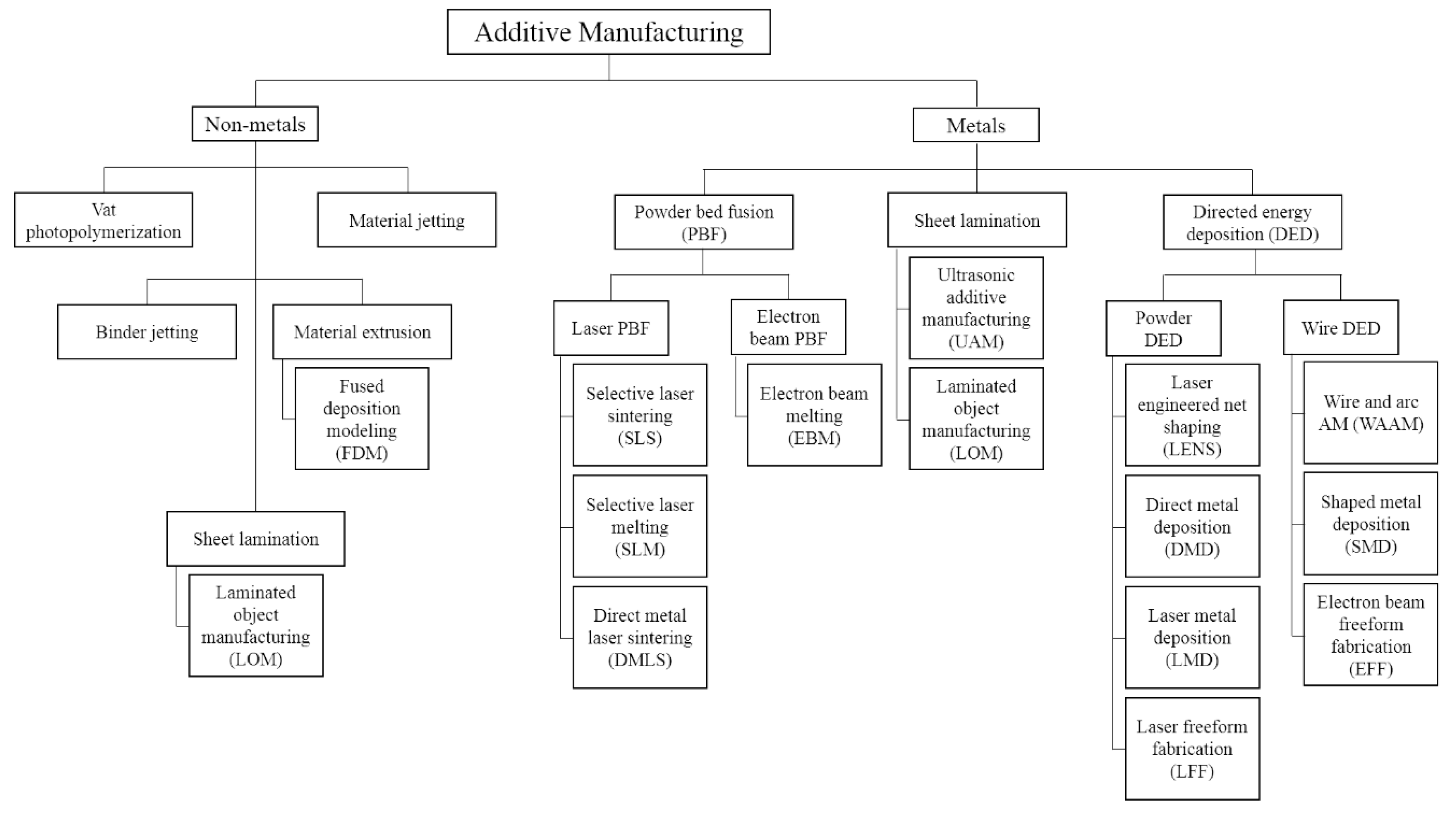
3. Classification of AM for Manufacturing Metallic Components

Currently, there is a wide range of available AM technologies, with each process offering particular advantages and drawbacks depending on its service application. These AM processes are categorized into photopolymerization, material jetting, binder jetting, material extrusion, powder bed fusion (PBF), sheet lamination, and directed energy deposition (DED), as shown in Figure 1 [30]. The focus of this review is on metal-based AM technologies and mainly PBF and DED categories, as they are the most applicable to the aerospace industry.
The nomenclatures used throughout industry can sometimes be contradictory, particularly between complete-melting versus partial-melting (sintering). Many companies that utilize a particular AM category either alter the process slightly or call the process by a different name, which can complicate classifications. Table 2 lists the common acronyms and trade names associated with the main metal AM processes.

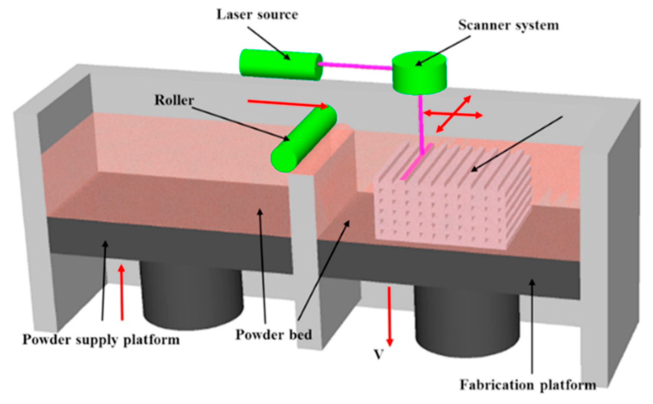
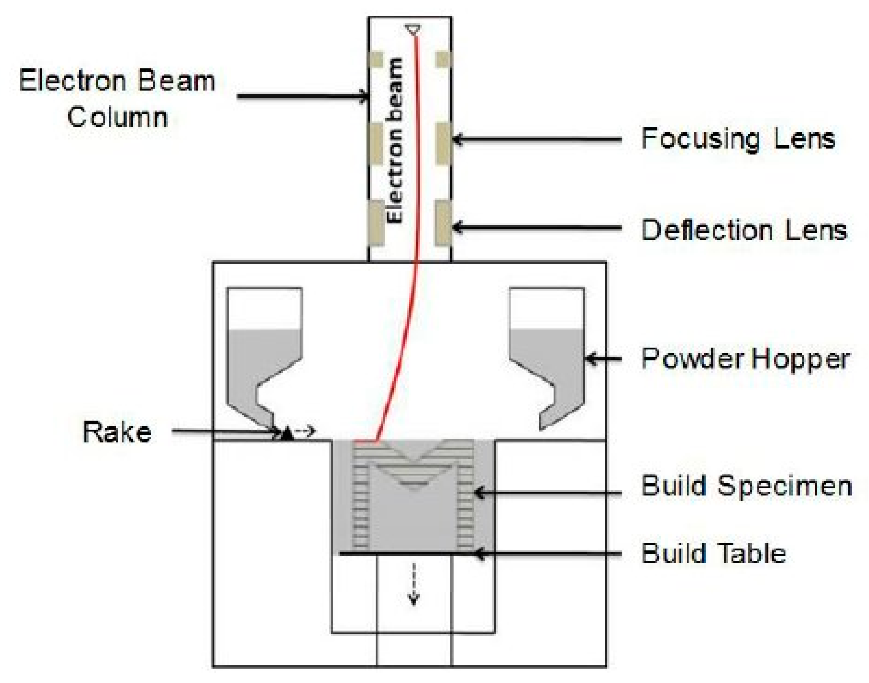
3.1. Powder Bed Fusion

In terms of utilization in the aerospace industry, the primary PBF techniques comprise of selective laser melting (SLM) and electron beam melting (EBM) [19,35,36]. PBF uses thermal energy to selectively melt regions of a powder bed layer that are evenly spread across a build surface using a recoating system. Once the layer is deposited, a powerful laser (L-PBF, e.g., SLM) or electron beam (E-PBF, e.g., EBM) precisely melts a particular location on the powder bed in a layer-wise manner (usually 30–50 µm thick per layer) according to the initial computer aided design (CAD) design, as shown in Figure 2 [37]. Once the entire layer is successfully melted in correspondence to the CAD model, the build-surface sinks down and a fresh layer of powder is swept across again, and the process restarts for the next corresponding layer. Typically, the motion of the laser or electron beam imparted onto the powder material is such that it melts previously solidified layers, which enhances interlayer fusion with successive layers and produces near-isotropic mechanical properties [35]. Furthermore, PBF AM techniques utilize the same underlying material deposition method by using a rolling or raking mechanism to spread uniform powder bed layers over a build platform.
The PBF approach is only economically viable if unfused powder is recycled after each printing cycle, for example by sieving. However, the recycling procedure can alter powder chemistry and particle diameter distribution. This can lead to increased porosity and voids upon subsequent printing due to the altered mean diameter distributions, with fine powders usually being removed during the powder recycling process [20]. Nevertheless, the use of fine, spherical metallic powders permits high packing densities, which improves part consolidation and reduces defects [38].
In addition, the PBF approach does not require structural supports because the high powder density across the build geometry can act as a self-support. This permits faster post-processing and simultaneous printing of several components within the same build volume in a single operation, therefore optimizing the AM building process. Furthermore, PBF techniques offer higher precision compared with other AM processes.

3.1.1. Selective Laser Melting

In SLM, the build operation typically takes place in a vacuum or inert atmosphere (argon or nitrogen) to prevent the formation of surface oxides on the molten metal layers. The SLM process is very similar to direct metal laser sintering (DMLS) and SLS, with both undergoing a complete powder melting regime (Figure 3 [39]). The laser beam provides sufficient energy to raise the powder above its melting temperature, creating a small region termed the ‘melt pool’ at an exact location that corresponds to the 2D projection of the CAD model.
While SLS can utilize a range of polymers, metals, and alloy powders, and DMLS exclusively metals, SLM is primarily focused on particular metals such as steel, aluminum, and titanium [5]. However, both DMLS and SLS lack the capability to fully melt the deposited powder material while SLM has the ability to do so, resulting in the latter’s superior mechanical properties [40]. The primary benefit of SLM and of PBF in general is its ability to produce components of high resolution and quality, making its applications in the aerospace industry particularly useful.

3.1.2. Electron Beam Melting

The EBM technique uses a high-energy electron beam to melt a metallic powder bed region and is typically carried out in a vacuum to prevent unwanted oxidation and the reflection of highly energized electrons with the surrounding atmosphere [24,41,42]. The schematic of an EBM machine is shown in Figure 4 [42]. EBM was commercialized by the Swedish company Arcam, a now-subsidiary of GE Additive, and follows similar principles to electron beam welding [43,44]. In contrast with SLM, EBM transfers its energy at around 70% the speed of light via the kinetic collisions between accelerated electrons and the powder bed region. As a result, the energy supplied by the electron beam is not only enough to melt the powder; it also increases the negative charge of the powder [22,45]. The effect of this electronegativity can result in a more diffuse energy beam as the powder repels incoming electrons [46]. Typically, the chamber that houses the powder bed for EBM is pre-heated prior to the printing process to mitigate the effects of large temperature gradients and residual stress build-ups and to prevent the formation of undesired microstructures that could compromise the quality of the as-fabricated components, e.g., α’-martensites in steels [38,47].

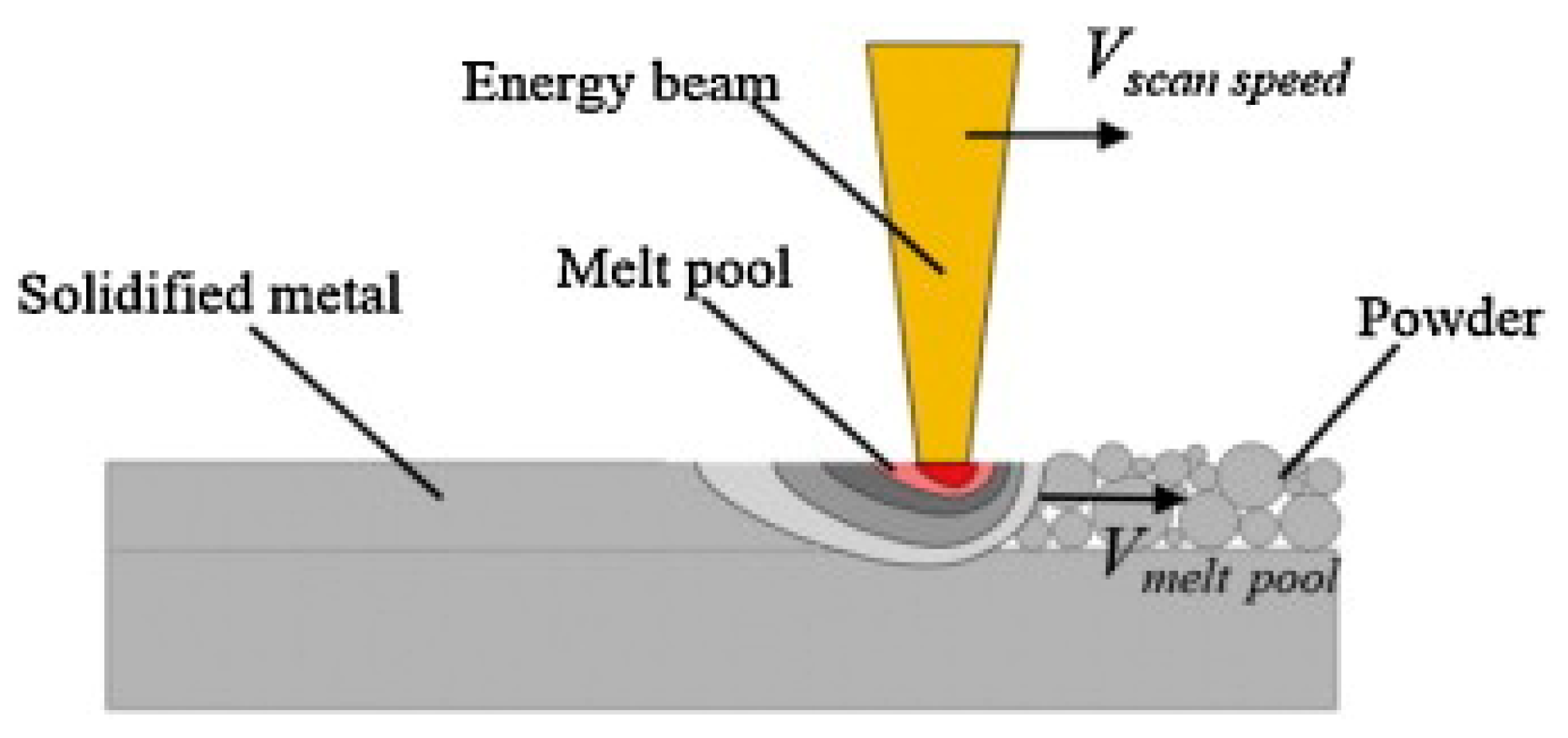
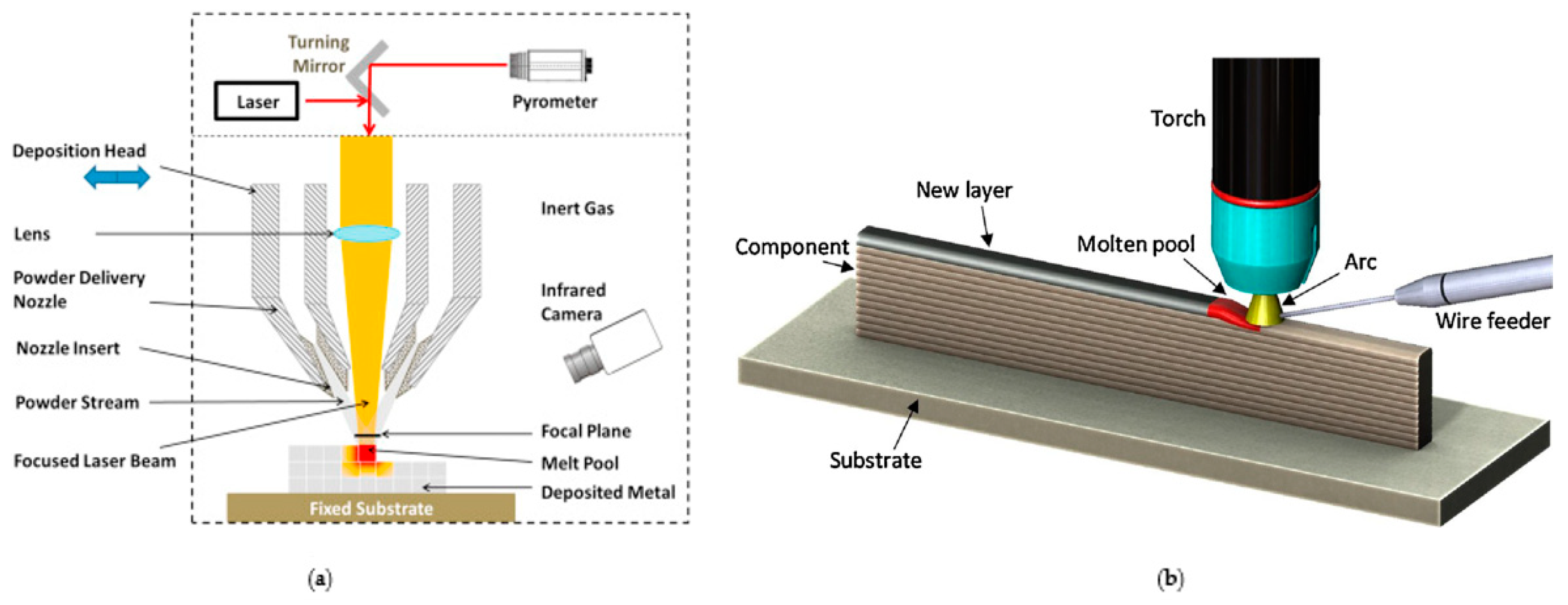
3.2. Directed Energy Deposition

Various commercial AM techniques fall under the DED category, including laser cladding (LC), laser engineered net shaping (LENS), and wire and arc AM (WAAM). In DED processes, metallic components are produced by layer-wise melting of input materials, either from a powder-fed or wire-fed configuration, as shown in Figure 5 [48,49]. The metallic wire or powder is directed into the focal point of a high-energy heat source such as a laser or plasma arc typically mounted upon a multi-axis arm, which in turn produces a small molten pool on the build area [50]. The method of material delivery in DED processes distinguishes itself from PBF systems. In addition, DED has similarities to multi-axis welding processes and has been used for producing components from high-performance super alloys [51]. Due to its localized melting and rapid cooling approach, the resulting microstructure can consist of well-refined grains and has been shown to exhibit 30% higher strength than conventional casting [35].
As its approach is not restricted to the powder-bed construct, DED has shown unique advantages in the repair of worn and damaged large-scale metal components by restoring their original geometries [52,53,54]. In addition, DED has the added ability of depositing coatings upon a substrate, often with protective or fatigue-life enhancing properties [55]. Furthermore, the DED process configuration permits the production of components with heterogenous material composition, as shown in Figure 6 [56]. By switching the input-material feedstock, layers of material with different compositions can be deposited on the build area. This approach is often used for repairs to give enhanced corrosion and wear properties to the component [57,58]. Moreover, compared to PBF systems, the heat conduction in DED processes is more effective because the heat, material, and shield gas are transferred directly from the nozzle to the build area, whereas the powder bed in PBF systems acts as a heat insulator [12]. This deficiency in PBF machines often causes incomplete powder melting that eventually leads to formation of porosity and other defects upon solidification, which may be detrimental to the structural integrity and mechanical properties of PBF-fabricated parts. It is also known that the heat source movement (laser or electron beam) in PBF machines is very fast compared to the nozzle movement in DED facilities, thereby leading to sharp thermal cycles that further exacerbate the porosity and defect problems during solidification [11]. Since these problems are less observed in DED processes due to their relatively more effective heat transfer and less sharp thermal cycles, DED processes often yield more consistent builds than PBF systems, thus improving productivity [11,15]. Though the deposition rates of DED techniques can be up to 10 times higher than PBF, this often results in DED-fabricated components having a larger layer thickness, which increases the surface roughness and reduces component accuracy compared to PBF (±1 mm for DED versus ±0.05 mm for PBF) [59,60].

4. Metallic Materials Used for AM in the Aerospace Industry

In recent years, common metallic materials used to fabricate components for the aerospace industry have included tool steels and stainless steels, titanium, nickel, aluminum, and alloys of these materials [61]. Other metals, such as gold, platinum, and silver, are also used in select applications in the aerospace industry [24]. In particular, nickel-based superalloys have been increasingly used due to their remarkable properties at elevated temperatures which are well-suited for aerospace components that are typically operated in extreme environments [62,63].
Furthermore, the Ti6Al4V alloy has gained widespread attention in the aerospace industry due to its combined properties of high strength and fracture toughness, and low density, together with a low coefficient of thermal expansion [64,65,66]. In addition, its high corrosion resistance is attractive as a lightweight material option for aerospace structures [38]. At the moment, the cost and difficulty of processing the material via CM techniques are significant due to CM’s high affinity with interstitial elements at elevated temperatures. Hence, manufacturers are increasingly utilizing AM to produce titanium components as AM offers tremendous design and processing flexibility, drastically reducing production costs and associated material waste [64]. So far, titanium alloys (for example, Ti6Al4V and TiAl) have been additively manufactured to produce turbine blades for commercial aircraft due to their good mechanical properties at elevated temperatures [67,68].
In most evaluations, the cost of material for AM is higher than its CM equivalent, but optimized AM processes can offer lower buy-to-fly ratios and recycling capabilities, significantly reducing the overall manufacturing costs [56,69,70].

5. Applications of Metal AM in the Aerospace Industry

The successful adoption of AM technology within the industry depends on its ability to reduce manufacturing costs and lead times without compromising the quality and mechanical properties of the finished product. In recent years, AM has had considerable success in prototyping within the aerospace industry, permitting rapid design and product modification, which in turn has enabled the final components to be manufactured quickly without a long lead time. In conventional SM processes, the fabrication of a product typically begins from a large billet that is subsequently machined down to the desired shape. Hence, manufacturing multiple components requires more billets to be machined down, resulting in poor material utilization and a high material wastage of around 90%, with high buy-to-fly ratios (typically 10:1) [41]. The significant advantage of AM over CM is its ability to create near net-shaped products, culminating in near 1:1 buy-to-fly ratios and scrap rates of only ~10–20%, significantly reducing the usage of input material and the need for post-processing machining [6,71]. At present, there are several advantages and drawbacks associated with AM application, as shown in Table 3.

5.1. Propulsion System in Aircraft and Space Transportation

In recent years, General Electric (GE) has been at the forefront of AM adoption for aircraft propulsion systems, integrating several AM technologies into new product developments. In 2016, the company founded a new subsidiary, GE Additive, via the acquisitions of high-profile AM companies such as Concept Laser and Arcam [43,72]. One landmark application has been the successful AM fabrication of 19 individual fuel nozzles made of titanium to be used in a single commercial “Leading Edge Aviation Propulsion” (LEAP) engine by “Cubic Feet per Minute” (CFM) International for the use of B737MAX and A320neo aircraft [73]. The AM fuel nozzle has several advantages over its predecessors that have been manufactured via CM approaches, including a five-fold increase in durability, 25% lighter frames, and facilitated part consolidation. This allows for the complete nozzle, including its complex internal cooling pathway features, to be built in a single AM machine operation; the nozzle otherwise requires 20 individual components to be built and assembled when manufactured by SM techniques, e.g. computer numerical control (CNC) machining [74,75]. Although GE initially successfully fabricated a T25 engine sensor housing component by AM prior to the AM fuel nozzle, it was only used for retrofitting hundreds of GE90-94B engines [76], whereas the fuel nozzle is in serial production [77]. In addition, GE has also managed to additively manufacture an advanced single turboprop engine for the Cessna Denali aircraft consisting only of a 12-part assembly, compared to the 855-part assembly required when manufacturing was performed by [78,79,80].
On the other hand, a research group at the Marshall Space Flight Centre (MSFC), part of the NASA, helped co-develop a simplified metal AM procedure for rapidly producing regeneratively-cooled nozzles for rocket engine applications in 2017 [81]. The manufacturing of rocket engines is inherently complex, as the system must be able to withstand both extreme pressure and temperature fluxes. However, MSFC managed to use a DED-based AM technique called laser wire direct closeout (LWDC) to fabricate the nozzle which incorporated improved complex coolant channels in a single build [82]. This technique allows for bimetallic printing and specifically for an internal copper liner for the coolant channels and an exterior jacket made of a nickel-based superalloy [83]. In addition, LWDC has been shown to drastically reduce the manufacturing time from several months down to weeks. The printed nozzles were tested under extreme operating conditions, successfully burning for 1040 s with minimal damage to the internal coolant channels detected upon post-evaluation [83].
Similarly, in the private aerospace industry sector, companies such as SpaceX have successfully fabricated SuperDraco engines to be placed onboard the main Dragon V2 capsule by using SLM techniques [84]. The primary purpose of this regeneratively-cooled engine is to evacuate the capsule in the event of an accident. These engines have been made of the Inconel superalloy (nickel–iron alloy) and have been observed to be able to produce 73 kN of axial thrust.
Furthermore, GKN Aerospace, formerly known as Guest, Keen and Neetlefolds (GKN) have recently begun to additively manufacture full-scale turbines for the Prometheus engine used by the ArianeGroup [85]. In addition to significant part consolidation and an estimated 90% reduction in manufacturing cost, the use of AM is expected to make the Prometheus engine the first rocket propulsion system to take full advantage of AM for commercial space propulsion operations [86].
Another development of AM for propulsive applications is in the manufacturing of RS-25, historically used as the primary space shuttle engine and also used for its future successor, the Space Launch System, which has resulted from collaboration between NASA and Aerojet Rocketdyne [87]. The components that have been produced by AM as a result of this collaboration include the pogo accumulator, which was designed to act as a shock absorber during ascent and a regulator to the supply of liquid oxygen [88]. With the application of AM, more than 100 welds have been eliminated from the component, reducing costs by 35% and lead times by 80% [88].

5.2. Structural Components for Aircraft and Spacecraft

Significant efforts have been made in recent years to insert AM componentry into both structural and propulsion systems of aircraft. Airbus used AM to produce A350 brackets from Ti6Al4V in 2014, the first metal AM components used for the interior of a commercial aircraft (Figure 7) [56]. The topology-optimized component is 30% lighter than a CM-milled bracket, yielding a significant waste reduction of from 95% to 5% [89].
A major breakthrough came in 2017 when the Norwegian company Norsk Titanium received approval from the Federal Aviation Administration (FAA) to fabricate components for the commercial B787 Dreamliner using DED AM techniques [90]. The company was the first to receive FAA approval to utilize AM for building components that will experience in-flight stress loads [91]. Later in the same year, Airbus began serial production of AM titanium brackets to be used inside the pylons of the A350 XWB aircraft, which link the wing and the engine [92].
Additionally, the Chinese-built Comac C919 was the first to manufacture central wing spars from titanium using the LC technique, a derivative of the DED AM category [93]. It is expected to enter commercial service onboard the aircraft in 2021.
On the other hand, as a consequence of the extreme operating environment, vessels traveling into space are exposed to stringent developmental and manufacturing procedures which are necessary to minimize part failure and ensure flightworthiness [24]. An important reason for this is that once launched, repairing a broken component onboard a vessel becomes exponentially difficult, particularly if it is launched beyond the low Earth orbit (LEO). Furthermore, component failure onboard a spacecraft can have tremendous consequences to the spacecraft depending on its mission criticality designation. With stringent qualification standards, the space sector saw very few AM utilizations until recently, although experimentation with the technology has been well-documented [94,95].
The earliest use of AM for structural applications in a spacecraft was onboard the 2011 Juno mission to Jupiter in the form of waveguide brackets, which were manufactured using EBM (Figure 8) [96]. On the other hand, an aluminum-based engine mount onboard the Israeli lunar lander Beresheet was expected to become the first AM component to ever land on the moon in early 2019, although it eventually experienced critical mission failure upon its final descent [97,98]. As AM technology has continued to mature, confidence throughout the industry has increased significantly over the last decade, and it is predicted that AM will take on a larger role in the fabrication of structural components for satellites [56,99,100,101].

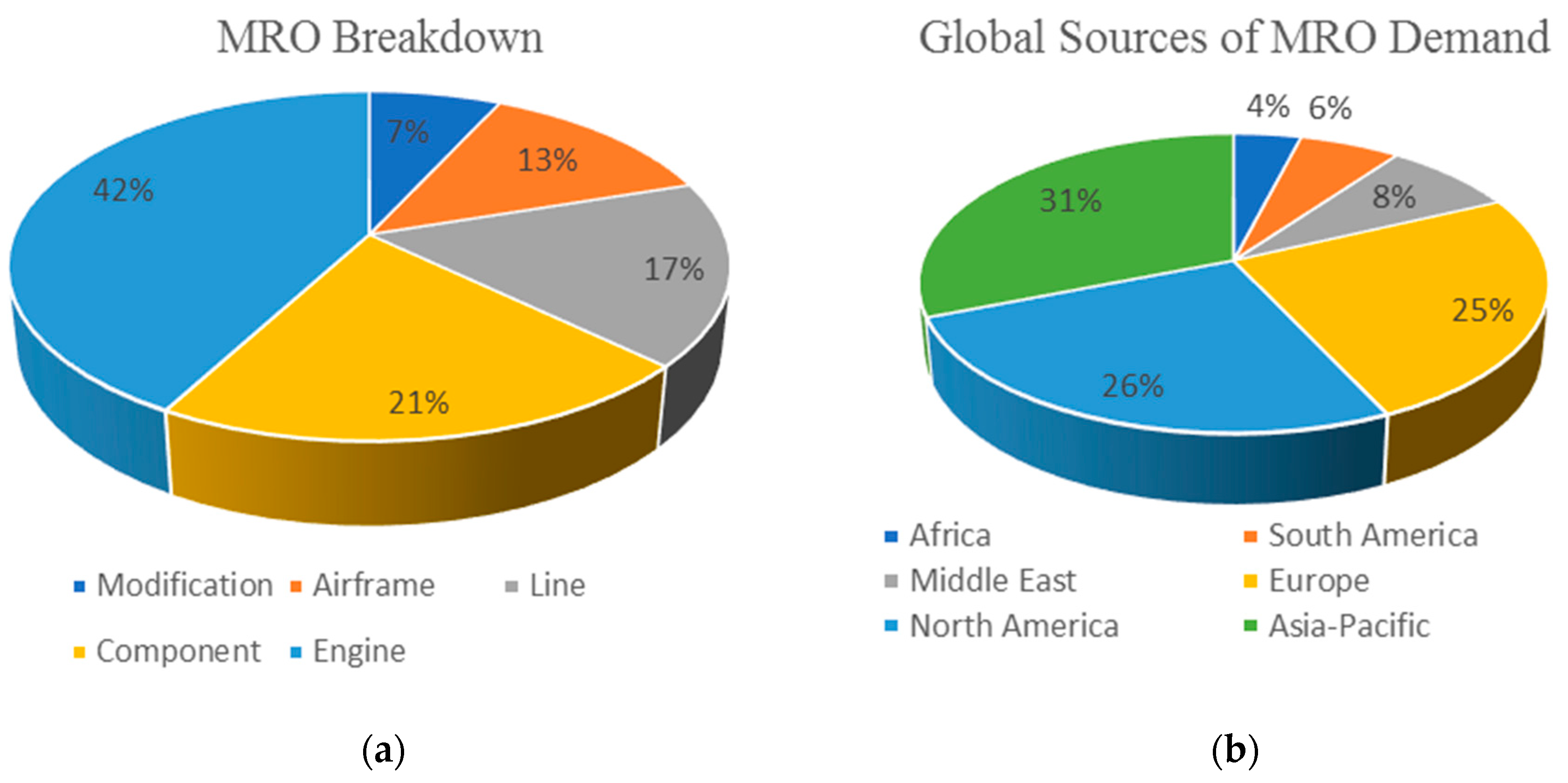
5.3. Maintenance and Repair of Aircraft Components

The typical lifespan of a commercial aircraft stands at around 20–30 years, and with this longevity comes scheduled maintenance [50]. There are typically over 30,000 individual components in the propulsion system of an aircraft alone that require periodic maintenance and repair [102]. To address these needs, specialist companies exist to provide maintenance, repair, and overhaul (MRO) services. High overhead costs exist for MRO providers to maintain large replacement inventories and to face uncertainties over future product demands. The economics of scale under AM permit an economically significant reduction in part inventory, in addition to being able to produce one-off replacements, an option which is prohibitively expensive with CM [7].
With stringent standards set in place to assure that the overhauled components are fit for service, MRO providers are required to have approval by aviation bodies such as the European Aviation Safety Agency (EASA) and FAA, depending on operational locations. The turnaround period for MRO providers is viewed as an important performance indicator to keep aircrafts operational by minimizing repair time, which could eventually maximize airline profits. AM has the potential to offer significant reductions in design and lead times which are highly advantageous for MRO providers [103].
MRO providers account for 40–50% of the total revenue of the aerospace industry, particularly in the spare components aftermarket, which generates larger profits than initial component sales [104]. In 2017 alone, MRO services accounted for $75.5 billion, with the Asia-Pacific, North America, and European regions being the largest markets (Figure 9) [105].
Future demands for MRO services are expected to increase for emerging economies in the Asia-Pacific region, especially for China and India. As shown in Figure 10, extended economic growth has spurred significant advancement in their respective middle classes, and investments for building new civilian airports and various supporting infrastructures are projected to double in the coming decades [106,107,108]. Domestic airlines are responding to this rise by placing increased orders for future fleets [109,110]. Following this rise in global demand, the through-life-support of aircraft components is estimated to be $1.9 trillion between 2016 and 2035, thereby offering large growth opportunities for MRO providers [19]. To meet the increasing demand, the inclusion of AM in MRO services is able to significantly reduce lead times and associated costs.
Over the course of its lifespan, an aircraft component can experience degradation as a consequence of harsh environmental and operational conditions [111]. Typically, conventional techniques such as tungsten arc welding (TAW) and tungsten insert gas (TIG) welding have been used to repair worn and damaged components [112]. However, the high operational temperatures in welding (around 5500 °C) can be detrimental to the microstructure of the repaired components [52]. In addition, manual post-processing such as grinding and machining are often required, which increases lead times. These inherent issues in conventional repair methods make a strong case for the growth prospects of AM-based repairs.
At present, additive repairs involve hybrid manufacturing, in which the most common approach is to firstly sandblast the surrounding damaged area and then deposit melt metal powder on the damaged area, followed by a CNC milling process to remove surplus material [113]. Currently, the hybrid manufacturing approach is necessary to improve the surface finish because as-repaired AM parts typically have a rough surface, which could compromise their tensile strength and fatigue properties [114]. In addition, AM product repairs can reduce the cost of re-manufacturing by 50% compared to CM approaches, significantly reducing lead times [115]. AM repairs are currently restricted to secondary structures due to the lack of certification and standards from aerospace regulatory bodies, although they show future promise for primary structure repairs. Over the last half-decade, there has been a trend of both airlines and manufacturers partnering with AM-capable MRO providers due to AM technology being recognized for its economical and reliable repairs [116,117].
Of the AM technologies capable of performing repairs, the most common approaches have been DED and supersonic particle deposition (SPD). Unlike the AM processes previously discussed, the unique characteristic of SPD is that the deposited powder material retains its initial phase composition and grain structure upon its base component [118]. On the other hand, DED is often utilized more extensively as it offers the ability to repair critical components to higher degrees of accuracy [119,120]. The benefit of both AM technologies is their capability to repair components with a reduced heat-effected zone (HAZ) [121].

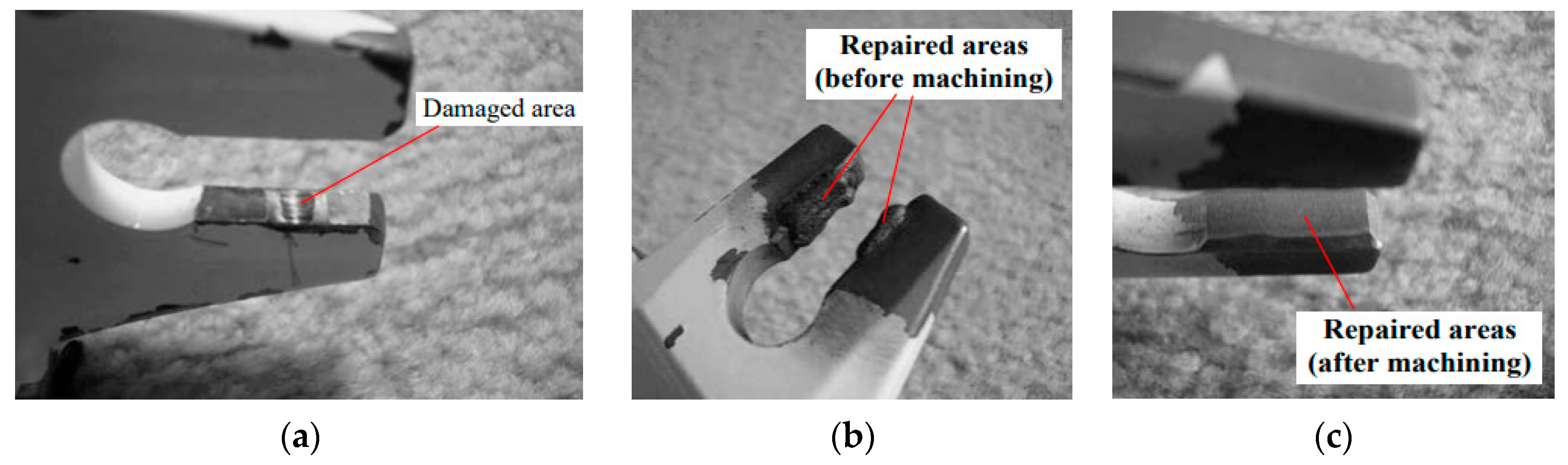
5.3.1. Repairs Using Directed Energy Deposition AM

DED AM technology (Figure 5) utilizes streams of metallic powder or wire being fed into the path of a laser or energy beam, producing a moving melt-pool on a build area [122]. In contrast with the SPD technique, DED does not require a line of sight when depositing material since material is fed automatically with a laser beam via a coaxial nozzle [50]. DED operates at lower heat input, generating minimal HAZ and dilution of the build area, often requiring only minimal post-processing [123]. Furthermore, DED-based repairs have been shown to reduce re-manufacturing costs by approximately 50% [115]. Overall, DED has several advantageous characteristics that prove its noteworthiness in repair and restoration of aerospace components. The advantages and disadvantages of the DED process for repair of aerospace components are shown in Table 4.
Figure 11a–c show an example of the reparation of a worn anti-rotation bracket of the F/A-18 rudder from military service in the Royal Australian Air Force (RAAF) [58]. Although newly purchased anti-rotation brackets are relatively cheap, long lead times of up to 18 months drew the attention of the RAAF to additive repairs and specifically to those by DED. In this case, stainless steel powder was successfully deposited on the damaged area using a 6-axis robot arm, followed by post-machining to restore the bracket to within its original geometric tolerances. Following the repair, the anti-rotation bracket successfully satisfied all requirements for re-certification and was endorsed by the air force.

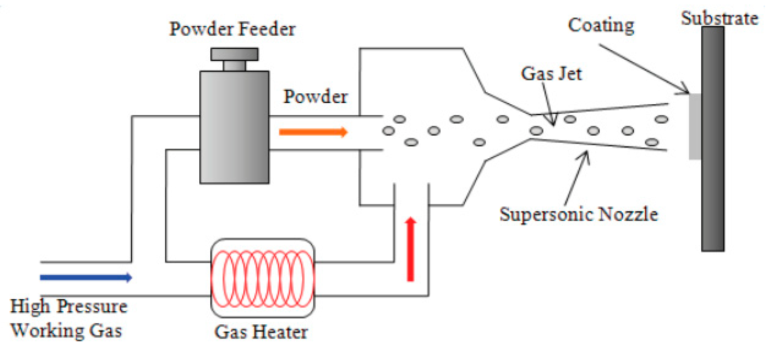
5.3.2. Repairs Using Supersonic Particle Deposition AM

The SPD technique, also referred to as cold spray or kinetic spraying, is a solid-state AM technology that restores damaged parts caused by wear and corrosion to their original critical dimensions. This process involves the jetting of metallic particles through an expanded supersonic gas flow, providing the particles with sufficient kinetic energy to impart plastic deformation and bonding to an impacted surface (Figure 12) [125]. As the metal particles are pushed through a Laval nozzle the flow temperature drops as the particles are accelerated by up to 1200 m/s [126], resulting in metal droplets being deposited on the targeted area to cover the damaged region. Thus, the SPD technique is viewed as a viable and effective repair solution for damaged components, in addition to DED repairs.
With a particle size distribution ranging from 5–45 µm, the result of the high-energy impact of the particles is high strain-rate deformation and adiabatic shear at the impacted surface [50,127]. With its ability to produce compressive stresses on the impacted substrate and lack of an HAZ, SPD has been shown to restore and mitigate material degradation in structural aircraft components that have been exposed to both corrosion and wear for parts such as load bearing wings, horizontal stabilizers, and fuselage lap joints [50,128]. Typically, the materials used for SPD restoration and repairing works including aluminum and titanium alloys, and nickel-based superalloys [127]. Furthermore, SPD is a controllable method because it can be used to regenerate worn components and return them to their respective high dimensional tolerance [50]. This gives SPD several advantages and disadvantages over traditional welding approaches for component repairs, as shown in Table 5.
Similarly to other areas of AM applications, SPD has its applications limited to secondary accessory components such as gearboxes, pump housings, and valve bodies for turbine engines [131]. SPD has also been used to repair components for the military USAF B-1 Bombers and F/A-18 fighter jets, successfully reducing the cost of repairs [132,133,134]. In late 2018, the FAA approved certification for SPD-based repairs provided by the Airborne Maintenance and Engineering Services (AMES) partnership with the University of Akron [135]. The long-term goal for SPD is to transition the technology into repairs of primary aircraft structures, which could be attractive to commercial aircraft operators since these repairs are typically more costly using conventional techniques [136].

5.4. Manufacturing Spare Parts for Legacy Aircraft

A legacy aircraft is considered a make or model of aircraft that is no longer in production, thus making component replacements difficult to source at times. Specialist companies that undertake MRO work are attempting to address the issue of supply for legacy aircraft replacements. This issue is further exacerbated if the original supplier of the required components goes out of business, taking company intellectual property away with it. In some instances where MRO providers have been assigned to repair or replace legacy aircraft components, the advantages of AM become apparent as original equipment manufacturers (OEMs) may no longer carry the associated tools for the specific model [6].
AM is more cost-effective for low volume productions as it does not need supporting fixtures and tooling to produce the required parts. This pushes AM into the spotlight as low production runs are often commonplace, particularly if customers need one-off products [10]. The United States Air Force (USAF) has partnered with America Makes, an American-based AM innovation institute, with the objectives of supplying on-demand production in and reducing lead times for replacement and maintenance components of legacy aircrafts [137]. The underlying economics of low-volume manufacturing results in reduced inventory of parts, therefore shifting companies towards an on-demand manufacturing approach [7,138]. In addition to minimizing inventory, implementation of AM systems has been shown to reduce the cost of waste material disposal [139].

6. Current Outstanding Issues for Metal AM in the Aerospace Industry

6.1. Standards and Certification Qualifications

Despite the numerous advantages and applications of metal AM technology in fabricating various individual structural components for a particular aircraft, e.g., turbine blades and engine mount, the utilization of metal AM to manufacture primary structure and mission-critical parts remains scarce. This current gap is primarily caused by a lack of technological standards due to the rapid growth of metal AM technology in recent years. The establishment of standards would ensure (i) consistency, repeatability, and reliability of AM-fabricated aerospace components across all commercial companies worldwide and (ii) reduce the likelihood of critical components failing during service.
Increasingly stringent sets of testing protocols and certification steps have been established by major governing bodies such as the FAA and EASA before clearing any aerospace components for service, depending on the required application [140]. Such certification typically involves the demonstration of the repeatability of the production process and the consistency of the quality of as-fabricated components. However, process repeatability and quality consistency remain major issues in metal AM technologies used in the aerospace industry, particularly when manufacturing parts in large quantities.

6.1.1. Barriers, Challenges, and Opportunities

There is general consensus throughout the industry that a large gap exists in the applicational knowledge of AM technologies and their corresponding implementation procedures into commercial products. Therefore, the training, education, and mindset shift among engineers and company executives on the uses of AM are deemed necessary and are currently under development [141,142]. The major obstacle surrounding certification guidelines is the scarcity of knowledge regarding the failure mechanisms of AM-fabricated components and in particular the fatigue properties that are of critical importance within the aerospace industry due to the cyclic nature of the loadings experienced by aerospace components. This is due to the current lack of part-driven data regarding key printing process parameters, material properties, and microstructures, and the resultant mechanical properties, which is exacerbated by inadequate on-site process monitoring and often prohibitive high costs of non-destructive testing techniques. However, the tremendous design flexibility of metal AM techniques opens up opportunities for a hybrid AM/SM approach, topology optimization (TO), and design for additive manufacturing (DFAM), which would undoubtedly improve the processing and quality of metal AM-fabricated aerospace structures.

Fatigue Properties of AM-Fabricated Aerospace Components

While static mechanical properties such as hardness, yield strength, and ultimate tensile strength (UTS) of metal AM parts have been extensively studied and are well documented [12,13,22,24], dynamic properties such as fatigue and creep have been much less investigated and reported within the available AM literature [14]. In fact, fatigue life is considered of critical importance for aerospace components as they undergo cyclic loadings for a sustained period of time, often at elevated temperatures during service.
The lack of fatigue test reporting, particularly for AM-fabricated aerospace components, could be attributed to the scarcity of unified aerospace application-centered nomenclature and test standards. Unlike the investigation of static properties in which conventional standards can be modified to cater for AM materials, the utilization of established standards for fatigue testing for CM metallic parts such as ASTM E0466, ASTM E0606, ISO 1099:2006, and ISO 1143:2010 could pose challenges and uncertainties when testing for AM-fabricated aerospace parts due to the stringent qualifications and protocols within the aerospace industry [27,94,95,143].
Nevertheless, available fatigue testing results within the metal AM literature have indicated that surface roughness, porosity, and defects all contribute to the wide scattering of experimental data for both low cycle fatigue (LCF) and high cycle fatigue (HCF) regimes [14]. Using Ti6Al4V as an example of the most comprehensively studied material for fatigue properties in both PBF and DED AM processes, the established consensus explains that although proper process control can improve the fatigue properties of as-built AM parts, their overall fatigue performances are still poorer than those of their wrought and cast counterparts [12,26]. Post-processing techniques such as machining and hot isostatic processing need to be conducted to improve surface finish and eliminate pores and defects to yield comparable fatigue performances to CM Ti6Al4V [12]. Since Ti6Al4V is one of the candidate materials for aerospace components, the available fatigue test results on metal AM can serve as a guideline when developing and integrating standards and qualifications for fatigue testing of metal AM parts fabricated from a wide range of materials and specifically for aerospace applications.

Non-Destructive Testing, Evaluation, and In-Situ Process Monitoring

An important challenge for AM components is the verification and mechanical testing of the as-fabricated components. In particular, conducting non-destructive testing (NDT) on AM-fabricated components to assess defects such as cracks, gas inclusions, and voids becomes increasingly problematic because of the complexity of the AM process due to the multitude of physical, chemical, and thermal phenomena occurring simultaneously during processing. Currently, the lack of an NDT test database for AM parts, coupled with the complicated procedural standards for testing, restrict AM from being applied at a global scale. Hence, new NDT techniques that are capable of minimizing component irregularities to a high degree of accuracy are urgently needed to ensure that the quality and consistency of AM-built parts are well-maintained throughout all production cycles.
An AM component that is to be used as a mission-critical structure requires more rigorous and thorough testing and evaluations compared to a non-mission critical component. These tests typically comprise of non-destructive evaluations (NDE), measurements of fracture toughness and fatigue properties, and proof testing, in which additional testing and compliance of the safe-life of the components often incur an additional certification expense to the manufacturer [144]. If the AM-fabricated component experiences breakdown or malfunction and the complete system can revert to safe operation automatically then the component only requires acceptance-testing rather than the various assessments mentioned previously. This is the major reason why most AM-fabricated aerospace components are restricted to non-critical services, allowing manufacturers to gain experience due to the reduced testing and analysis requirements [20].
Unlike established CM processes where in situ process monitoring is commonplace, numerous AM techniques have yet to completely incorporate monitoring technology on site. Although data are often gathered during printing cycles, they are simply stored and not utilized in real-time closed-loop feedbacks [145]. While AM providers offer the monitoring of select failure modes, such as porosities, melt pool, build-height, and melt-pool temperature, a unified industry-wide monitoring approach is yet to be developed and is one of the main subjects of ongoing research [146,147].
As AM products are process-sensitive, the lack of production constraints can compromise the geometrical accuracy and the quality of as-built AM parts when manufactured in large quantities. These could be attributed to critical issues such as gas porosity, internal cracks, lack of fusion between layers, and microstructural aberrations as a result of the lack of in situ process monitoring [148]. The development of in situ sensing and feedback control would help minimize build errors and reduce the need for subsequent expensive tests [149]. The advantages of including both physics-based models and in situ monitoring of AM processes are shown in Table 6.

Hybrid AM/SM Approach

It is well known that AM is a revolutionary manufacturing process that possesses the advantage of tremendous design flexibility, enabling metallic and non-metallic parts with complex and intricate geometries to be built in a single process sequence. However, the use of AM to manufacture high-performance metallic components requiring tight tolerances for critical applications such as in the aerospace industry is limited by the geometrical accuracy, part resolution, and surface quality that can be attained during the manufacturing process [150,151,152].
For both PBF and DED metal AM processes, the lack of geometrical accuracy (~5–20 microns) can be attributed to the layer-wise build-up philosophy of AM and the splitting of the CAD design into individual 2D slices, which introduces the stair-step effect [151,152]. On the other hand, the part resolution of metal AM parts is determined by the melt pool dimensions that can be controlled by optimizing process parameters [150]. Even when optimum process parameters are selected, as-built metal AM parts still have relatively high surface roughness, which reduces part quality and may result in poor fatigue performance [12,24].
Post-processing via SM, and in particular CNC machining, is typically carried out on as-built metal AM parts to provide the required surface finish and dimensional accuracy for service. However, such a hybrid AM/SM approach often requires significant manual human intervention both in the CNC path planning and machining execution, thereby incurring additional time and costs which are counter-productive, especially for high-stakes industries, e.g., the aerospace sector.
However, the benefits of a hybrid AM/SM approach could outweigh the disadvantages, provided that these combined techniques are streamlined into an integrated system. So far, researchers have worked towards developing a unified hybrid system that incorporates individual AM and SM capabilities within a single machine architecture, as detailed in various works [150,151,152,153,154]. The single hybrid machineries described in these studies are focused on merging and optimizing DED AM techniques to fabricate the metal parts, with multi-axis CNC machining used for the post-processing phase. These types of equipment are used for manufacturing new components, re-manufacturing and repurposing old components, and repairing damaged parts, all of which are well-suited to meet the demands for components within the aerospace industry.

Topology Optimization and Design for Additive Manufacturing

Light-weighting has emerged as one of the main priorities in the fabrication of high-performance metal AM parts for aerospace applications, driven by the demand of achieving greater sustainability and efficiency without compromising the mechanical properties and the overall performance during service [155]. To achieve these objectives, the advantages of a combined TO and DFAM approach can be exploited during the design stage while taking into account the geometrical and functional constraints of the intended end-applications.
TO refers to a process of altering the surface or topology of a structure by considering the associated design constraints via special mathematical algorithms through dedicated software during the initial design stage [156]. When considering the mass and functional constraints that are often imposed for aerospace applications, TO is applied during the design stage of metal AM processes with the view of reducing part weight/volume while still delivering high-performance parts. These objectives can be achieved by finding the best compromise between material distribution and the load carrying path across the intended structure [157].
On the other hand, a topologically optimized design does not necessarily translate to high quality as-built metal AM parts. DFAM aspects such as residual stress, build orientation, and support structure need to be considered to ensure that high-performance and complex geometry parts can be achieved in a practical and cost-effective manner [158]. For example, a topologically optimized DFAM is aimed at developing self-supporting structures, or structures with as little support as possible, to reduce material waste and incurred costs, while devising efficient heat transfer pathways to mitigate residual stress build-ups that could lead to part warpage [158,159].
Thus, the synergy between TO and DFAM is a promising approach to fabricating lightweight, topologically optimized aerospace components that can exploit the design flexibility advantage of AM processes. While research on TO-DFAM consolidation in metal AM fabrication of parts for the aerospace sector is still an ongoing research subject, there have indeed been some success stories. These include the successful redesign and manufacture of two actively functioning heritage parts of a technology demonstrator space mission in orbit that was commissioned by Surrey Satellite Technology Ltd., and that of five components for the lunar launch vehicle system of SpaceIL that will be launched very soon [159].

6.1.2. Current Standards and Certification Developments

The pressing need for industrial standards in metal AM processing has been a strong catalyst for cooperation among regulatory bodies for international standards. Several committees have been established through existing institutions, such as the ASTM F42 and ISO/TC261 committees that aim to establish standards on test procedures, materials, processes, and terminology for AM processes [160,161]. Both the American Society of Test Methods (ASTM) and the International Organization for Standardization (ISO) are responsible for the majority of universal AM standard publications, while SAE International focuses primarily on aerospace-related AM standards [162].
In an effort to further speed up programs on AM standards, major leading regulatory bodies such as SAE International, ANSI, ASTM, and America Make have frequently collaborated with regulatory bodies for aviation, such as the FAA, EASA, and NASA, in recent years [163,164,165]. In 2017, the FAA began developing a strategic roadmap draft for AM which outlined a multi-year strategy for certification guidelines and manufacturing policies on AM applications [141].
Industry-leading aerospace manufacturers such as General Electric (GE), Airbus, and Boeing also utilize their close relationships with MRO providers and regulatory bodies to further progress standard developments for AM [140,166]. In 2018, Boeing signed a five-year collaborative agreement deal with Oerlikon, a leading technology group, to focus on developing standards for AM processes and associated materials [167]. Furthermore, in early 2019, an SAE-led AM committee and Norsk Titanium released their first official specifications for DED-based processes [168,169,170].
It is believed that currently there are over 100 AM standards available; some of these are listed in Appendix A [140]. The contents of the standards cover a range of aspects, including the structure of the CAD file, model slicing, process conditions, and post-processing procedures. The existing standards can help to define specifications for qualification of metal AM components [144,171,172]. The primary issues that need to be addressed when developing AM standards and certifications are listed in Table 7.

6.2. Sustainability of Metal AM for Aerospace Applications

From a sustainability point of view, AM offers the advantage of high material utilization and low material wastage, in contrast with SM techniques such as CNC machining [7]. Even though the energy consumption during AM printing processes is currently higher per unit component produced, AM manufacturers can produce the exact number of parts required or fabricate multiple parts in a single machine operation, thereby offering improved performance efficiency [35,173].
In the face of global climate change, governments and aviation bodies such as the International Air Transportation Association (IATA) have set a goal of mitigating CO2 emissions in subsequent years and have released the following milestones for its member countries as guidelines towards achieving this goal [174,175]:
  • An average improvement of aircraft fuel efficiency of 1.5% per year from 2009–2020.
  • A cap on net aviation CO2 emissions from 2020 (also known as carbon-neutral growth).
  • A reduction in net aviation CO2 emissions of 50% by 2050 relative to 2005 levels.
To meet these milestones, aerospace companies are increasingly seeking to take advantage of AM technology, focusing on light-weighting of materials to reduce fuel consumption as well as component redesign and consolidation to improve the performance efficiency of their products [176,177].

6.2.1. Economic Sustainability

AM is beginning to mature from its initial prototyping designation back in the early 1990s, and an increasing number of aerospace companies are integrating AM into their production lines. Recent trends have shown increasing collaboration and partnership between aerospace manufacturers and AM providers, as well as acquisition and absorption of AM providers into the main aerospace companies [178,179,180]. From 2014 to 2016, the number of AM businesses providing metal AM machineries and associated equipment jumped from 49 to 97, representing 49% of the total number of AM providers [181]. In 2017, the aerospace industry accounted for 18.2% of the total AM market and is considered to be the most promising industry for AM utilization in the future [182].
Although limited literature on metal AM is available regarding long-term economic sustainability, manufacturers have recently begun to utilize life cycle assessments (LCA) to study the effects of a complete life cycle of an AM product with respect to its material and energy consumption [183]. From a worldwide perspective, taking into account all manufacturing industries, recent LCAs of various AM processes have presented the prospect of significant cost savings in the additive production of components which are estimated to be $113–370 billion by 2025 [184,185].

6.2.2. Energy Consumption and Savings Consideration

Based on the five stages of the AM life cycle shown in Figure 13, the majority of recent literature that focuses on the energy consumption of AM processes has been centered around processing and manufacturing (stage 2) and printing (stage 3) within the AM life cycle [186]. However, the majority of energy savings are expected to come from applicational use (stage 4). Using light-weighting as a base argument, the mass reduction obtained in AM-manufactured components corresponds to less fuel required for flight, which translates to less fuel consumption. Approximately 13.4–20 TJ worth of energy savings are estimated for every 100 kg reduction in aircraft mass across a typical 30-year service lifespan, significantly mitigating the high-energy consumption at the manufacturing stage [187,188]. The reduction of fuel consumption is of critical importance to the airline industry, since fluctuating fuels cost accounted for an estimated $180 billion in 2018, or ~23.5% of the total operating cost [189].
A viable approach to reduce energy consumption is to build several components in a single print cycle. For example, PBF processes allow for the unmelted powder to act as supports for the multiple parts fabricated within a single build volume, cutting down idle periods throughout the entirety of the print and lowering the cumulative energy consumption. As a result, the dependency on large centralized factories and assembly lines is reduced, further contributing to more savings in the overall operational cost. However, such energy savings currently can only be achieved for low-volume production runs, as the AM processes for metal powders consume a large amount of energy [140]. In situations which require minimal material removal, CM can be the most viable option, offering the fastest, least energy-input approach.
Nevertheless, the majority of energy consumption studies in the literature have focused primarily on direct energy consumption in AM and CM processes while neglecting energy consumption effects on a wider scale, such as stock-material production and pre/post-processing [188]. Several studies have attempted to measure the cumulative energy usage of various sub-systems within an AM system, often with varying results [41]. However, most of these studies have concentrated on plastic- and polymer-based AM processes rather than metal AM processes, which need further research.

6.2.3. Health and Safety Risks and Environmental Considerations

Existing research has revealed potential adverse health impacts on personnel operating AM machines or those working around other associated AM equipment and infrastructure [190]. The direct contact or inhalation of ultrafine metals and nanoparticles has been shown to potentially lead to serious health complications such as injuries to the lungs and nervous system, mental impairment, and various forms of cancer. Furthermore, if AM equipment or metal powder repositories are not grounded correctly, workers can be vulnerable to electrostatic discharges or sparks that could potentially cause fires or explosions and endanger workers’ safety.
Such health and safety risks can be mitigated by taking safety precautions such as conducting metal AM processing under vacuum or in an inert atmosphere and allowing for a cool-down period to enable residual powder particles to settle before removing the component from the build area. Furthermore, a combination of integrated AM cleaning systems can be introduced and breathing apparatus can be utilized during post-processing, such as part removal and handling. Recent publications have highlighted the gap in knowledge for long-term effects and suggest further research into the subject [191].
On the other hand, the high-energy input required per component during metal AM processing means that AM is not necessarily more environmentally friendly than its CM counterparts [192]. However, AM is able to improve overall manufacturing efficiency compared to CM because of its capacity to produce near-net shape components, which significantly reduces scrap rates and required input material. Furthermore, the initially higher footprint of AM processing with respect to CM is expected to be compensated by optimized in-use functionality of AM-built aerospace components, such as reduced component mass and improved aerodynamics [193]. Nevertheless, further LCA studies need to be conducted to assess the environmental impacts of AM technology.

6.3. Development of the Supply Chain for the Aerospace Industry

To date, AM manufacturing centers have mostly been located far from the reach of customers. The aerospace industry often facilitates a three-tiered supply chain structure to assure a continuous inflow of products, which include raw material and as-built part suppliers, OEMs, and companies that provide MRO services [140].
Recent studies have shown that the integration of AM into existing supply chain distributions within the aerospace industry has the potential to produce a more efficient and responsive supply chain. Presently, companies purchase and manufacture products according to estimates of future demands. When these demand estimates fall short, a large portion of the capital of a company becomes tied up in unsold inventory [194,195]. In particular, the large-scale production of unique spare components usually comes with a high risk of obsolescence [194]. Therefore, using AM to fabricate spare parts that are no longer being mass-produced by CM techniques would increase cost efficiency and enable economics of scale [17,196].
With the implementation of AM, there is potential for significant reduction in supply chain lengths as it offers manufacturing capabilities at regionally-located, de-centralized sites [197]. This would minimize the complexity of the supply chain, lower transportation and incurred costs, and reduce downtime for maintenance [22]. Furthermore, CM parts often require the assembly of many individual components, and component-heavy assemblies such as aircraft engines can result in lower reliability and longer inspection times. However, simplified part consolidation in AM techniques as a result of AM’s tremendous design flexibility means that a finished structure can either be built in a single AM machine operation or can be completed with minimum assembly required.
Hence, MRO providers aim to transition towards print-only facilities with an aim to reduce overhead costs, particularly for part inventories, and also to minimize their footprint [19]. However, a complete restructuring of current supply chains in favor of an AM-focused setup has not yet been shown to be advantageous when considering the present efficiencies of CM processes in large volume productions, coupled with the rapidly increasing global freight industry [198]. Furthermore, the possible long-term implications of AM-based supply chains are yet to be fully understood and require further investigation [199].

7. Discussion

The main objective of this review was to explore the current impact of metal AM application in the aerospace industry. In the early stages of its existence, AM was viewed primarily as a prototyping option with limited service application. As the years progressed, advances in technological capacities have permitted a gradual transition into primary product inclusion. These advances have been paralleled by exponential-like growth in the available global AM literature, patent submissions, and AM sales, both in academia and in the commercial sector.
As the repeatability and consistency of the mechanical properties of as-fabricated AM parts are yet to be completely understood, further development is needed with regard to the procurements of standards, certifications, and inspection protocols. In particular, the in situ monitoring of process parameters and physics-based modeling for the printing sequence (for example, a closed-loop feedback control) would help mitigate critical issues such as gas porosity and lack of fusion [200]. Furthermore, the AM field lacks an accessible material database, and the available Metallic Material Properties Development and Standardization (MMPDS) mainly focuses on CM methodologies. Nevertheless, MMPDS, AIAA S-110-2005, and TR-RS-2014-00016 are currently accepted worldwide as standards used to certify aerospace vehicles, and they can be used to develop future guidelines for AM qualifications [20]. As a result, many industry leaders and regulatory bodies such as ISO, ASTM, FAA, EASA, and SAE have collaborated to create numerous select committees which solely focus on the development of AM standards.
With regard to the aerospace industry, the majority of direct applications to date have been restricted to non-critical components, e.g., secondary or redundant structures. It is expected that industrial confidence, technological capacity, and familiarity will continue to grow, and AM applications will increasingly transition into more mission-critical componentries [201]. However, manufacturers are currently cautious about taking this leap of faith because any mission failures resulting from defective or malfunctioning AM components may result in the throttling of developments. AM can be difficult and expensive to integrate within the mainstream aerospace industry, particularly for small- and medium-sized OEMs that lack long-term research and development (R&D) capabilities [202].
In its current state, AM still cannot completely overtake CM but rather work in parallel with CM, in which case AM will be expected to become an essential method for manufacturing complex, high-end components. Since an AM system does not require tooling, it is more profitable than CM for low-volume production runs as the tooling cost often represents a major portion of the production cost. For high-volume runs, existing CM infrastructure permits batch productions at significantly greater efficiencies over AM. However, this is not an issue for AM since the aerospace industry often requires only low-to-medium volume component production.
With respect to the supply of spare parts for legacy aircraft, AM components can be scanned and turned into a 3D CAD model without the need to obtain original patterns and tooling from OEMs [203]. For damaged or worn components, DED AM techniques have shown promise in restoring original component dimensions, as well as in depositing heterogeneous protective coatings to enhance mechanical properties such as fatigue life. Though DED has been shown to offer impressive results regarding the repair of aircraft components, its integration is still lacking, although it could be improved in upcoming years.
In terms of the inherent energy consumption during metal AM processing, academic publications tend to conclude that even though the printing process is more energy intensive than CM, huge energy savings are attained when AM-fabricated parts are used in service. This is due to the ability of AM to reduce the mass of a component through optimization and light-weighting without sacrificing its mechanical properties. Over the course of the components’ in-service life, this optimization is expected to contribute to substantial reductions in CO2 release as a result of reduced fuel consumption.
With regard to the aerospace product supply chain, the long-term effects of large-scale AM-centered structuring remain to be seen, although the majority of available works are optimistic about the up-scaling of metal AM in the aerospace industry. However, in the immediate future, AM will be able to simplify supply chain structuring since it is able to reduce the dependency of MRO providers on large part inventories as on-demand AM fabrication becomes increasingly realistic.
The long-term outlook for metal AM in the coming decades provides insight into its use for in-space manufacturing (ISM), such as, for example, producing components outside the atmosphere in microgravity. The major premise of ISM is that raw material in bulk can be sent into orbit, offering higher payload volume fractions that could withstand greater G-forces upon ascent when compared to more fragile, pre-fabricated components. At present, for long-endurance spaceflight missions to planets or asteroids within the solar system, pre-fabricated parts for the mission must be launched from the ground into orbit, which means only limited payload volume fractions are possible and considerable geometric restraints for the payload structure need to be met due to dimensional restrictions onboard ascent vehicles [204]. For long-duration missions, the capacity of manufacturing components to be on-demand provides increased self-sufficiency and increases safety in the process [205]. Aside from long-duration spaceflight missions, recent publications have contended that ISM might also be utilized in the construction of nanosatellites and antenna parts, as well as for repairs of structural satellite components [204]. Though not likely to become commercially viable in the near future, ISM developments are currently on-going. For example, the International Space Station (ISS) was used as a test bed for non-metal AM research in 2014, producing dozens of acrylonitrile butadiene styrene (ABS) filament-based parts for repairs, upgrades, and installations of various ISS infrastructures onboard [206,207]. To date, the experiments performed have provided valuable insight into the mechanical properties of AM parts produced in microgravity, in which direct comparisons between in-space and on-ground AM components showed little discrepancy between one another [208]. Moreover, a hybrid AM module was recently sent to the ISS to demonstrate the capability of additively manufacturing new components with recycled plastics previously created onboard the ISS [209]. If successful, the knowledge acquired will help pave the way to increased self-sufficiency, which could be extended to metal AM in future extended space exploration missions [210].

8. Conclusions

As metal AM continues to evolve, the aerospace industry is currently gearing up to reap the benefits of this technology. Although issues surrounding product certification and sustainability still remain, significant progress is expected to come in the following years as regulatory bodies and industry leaders work together to establish standards and qualifications for metal AM. The numerous advantages of AM, particularly its design flexibility and low material wastage, have led to the integration of metal AM into current and future production lines by various aerospace manufacturers. Based on the recent success stories of industrial adoption and implementation, it has now become evident that metal AM is expected to have a long-lasting impact on the aerospace industry, paving the way for the next generation of product design.

Author Contributions

S.M.Y. contributed primarily to the writing and compiled the manuscript and some of the data collection; S.C. contributed primarily to writing the original draft, collection of references, and data curation; N.G. was heavily involved in project conceptualization, administration, and planning, as well as reviewing and editing the manuscript.

Funding

This research received no external funding.

Conflicts of Interest

The authors declare no conflict of interest.

Appendix A. Additive Manufacturing Standards

1. Government Documents [1,23]
TitleDescription
MSFC-STD-3716Standard for Additively Manufactured Spaceflight Hardware by Laser Powder Bed Fusion in Metals
NPR 7120.5NASA Space Flight Program and Project Management Requirements
NASA-STD-5001Structural Design and Test Factors of Safety for Spaceflight Hardware
NASA-STD-5017Design and Development Requirements for Mechanisms
NASA-STD-5019Fracture Control Requirements for Spaceflight Hardware
NASA-STD-6016Standard Materials and Processes Requirements for Spacecraft
JSC 65828Structural Design Requirements and Factors of Safety for Spaceflight Hardware
MSFC-SPEC-3717Specification for Control and Qualification of Laser Powder Bed Fusion Metallurgical Processes
2. Non-Government Documents [1,23]
TitleDescription
ASTM E8/E8MStandard Test Methods for Tension Testing of Metallic Materials
ASTM E21Standard Test Methods for Elevated Temperature Tension Tests of Metallic Materials
ASTM E399Standard Test Method for Linear-Elastic Plane-Strain Fracture Toughness KIc of Metallic Materials
ASTM E466Standard Practice for Conducting Force Controlled Constant Amplitude Axial Fatigue Tests of Metallic Materials
ASTM E606/E606MStandard Test Method for Strain-Controlled Fatigue Testing ASTM
ASTM E1450Standard Test Method for Tension Testing of Structural Alloys in Liquid Helium
ASTM E1820 ISO/ASTMStandard Test Method for Measurement of Fracture Toughness
ISO/ASTM 52921Standard Terminology for Additive Manufacturing-Coordinate Systems and Test Methodologies
SAE AS9100Quality Management Systems – Requirements for Aviation, Space and Defence Organizations
3. ASTM technology standards for Additive manufacturing [211]
TitleDescription
DesignISO/ASTM52915-16Standard Specification for Additive Manufacturing File Format (AMF) Version 1.2
ISO/ASTM52910-18Additive manufacturing—Design—Requirements, guidelines and recommendations
Materials and ProcessesF2924-14Standard Specification for Additive Manufacturing Titanium-6 Aluminum-4 Vanadium with Powder Bed Fusion
F3001-14Standard Specification for Additive Manufacturing Titanium-6 Aluminum-4 Vanadium ELI (Extra Low Interstitial) with Powder Bed Fusion
F3049-14Standard Guide for Characterizing Properties of Metal Powders Used for Additive Manufacturing Processes
F3055-14aStandard Specification for Additive Manufacturing Nickel Alloy (UNS N07718) with Powder Bed Fusion
F3056-14e1Standard Specification for Additive Manufacturing Nickel Alloy (UNS N06625) with Powder Bed Fusion
F3091/F3091M-14Standard Specification for Powder Bed Fusion of Plastic Materials
F3184-16Standard Specification for Additive Manufacturing Stainless Steel Alloy (UNS S31603) with Powder Bed Fusion
F2924-14Standard Guide for Directed Energy Deposition of Metals
F3213-17Standard for Additive Manufacturing—Finished Part Properties—Standard Specification for Cobalt-28 Chromium-6 Molybdenum via Powder Bed Fusion
F3301-18aStandard for Additive Manufacturing—Post Processing Methods—Standard Specification for Thermal Post-Processing Metal Parts Made Via Powder Bed Fusion
F3302-18Standard for Additive Manufacturing—Finished Part Properties—Standard Specification for Titanium Alloys via Powder Bed Fusion
F3303-18Standard for Additive Manufacturing–Process Characteristics and Performance: Practice for Metal Powder Bed Fusion Process to Meet Critical Applications
F3318-18Standard for Additive Manufacturing—Finished Part Properties—Specification for AlSi10Mg with Powder Bed Fusion—Laser Beam
ISO/ASTM52901-16Standard Guide for Additive Manufacturing—General Principles—Requirements for Purchased AM Parts
TerminologyISO/ASTM52900-15Standard Terminology for Additive Manufacturing—General Principles—Terminology
Test MethodsF2971-13Standard Practice for Reporting Data for Test Specimens Prepared by Additive Manufacturing
F3122-14Standard Guide for Evaluating Mechanical Properties of Metal Materials Made via Additive Manufacturing Processes
ISO/ASTM52921-13Standard Terminology for Additive Manufacturing-Coordinate Systems and Test

References

  1. George, C. Specification for Control and Qualification of Laser Powder Bed Fusion Metallurgical Processes; NASA Marshall Space Flight Center: Huntsville, AL, USA, 2017. [Google Scholar]
  2. Hart, J. An Introduction to Additive Manufacturing, Mechanosynthesis Group, MIT. Available online: https://www.youtube.com/watch?v=ICjQ0UzE2Ao (accessed on 23 March 2019).
  3. Wohlers, T. Early Research & Development. 2005. Available online: http://www.wohlersassociates.com/history.pdf (accessed on 9 February 2019).
  4. Wohlers, T.; Gornet, T. History of Additive Manufacturing. 2016. Available online: http://www.wohlersassociates.com/history2016.pdf (accessed on 9 February 2019).
  5. Ngo, T.D.; Kashani, A.; Imbalzano, G.; Nguyen, K.T.Q.; Hui, D. Additive manufacturing (3D printing): A review of materials, methods, applications and challenges. Compos. Part B Eng. 2018, 143, 172–196. [Google Scholar] [CrossRef]
  6. Coykendall, J.; Cotteleer, M.; Holdowsky, J.; Mahto, M. 3D Opportunity in Aerospace and Defense: Additive Manufacturing Takes Flight; Deloitte University Press: New York, NY, USA, 2014; Volume 1, pp. 1–28. [Google Scholar]
  7. Ford, S.; Despeisse, M. Additive manufacturing and sustainability: An exploratory study of the advantages and challenges. J. Clean. Prod. 2016, 137, 1573–1587. [Google Scholar] [CrossRef]
  8. Process Steps in the Metal Additive Manufacturing Workflow, Digit. Alloy. Available online: https://www.digitalalloys.com/blog/process-steps-metal-additive-manufacturing-workflow/ (accessed on 23 March 2019).
  9. Wohlers, T.T.; Campbell, R.I.; Caffrey, T. 3D Printing and Additive Manufacturing State of the Industry: Annual Worldwide Progress Report; Wohlers Associates: Fort Collins, CO, USA, 2016. [Google Scholar]
  10. Najmon, J.C.; Raeisi, S.; Tovar, A. Review of additive manufacturing technologies and applications in the aerospace industry. In Additive Manufacturing for the Aerospace Industry; Froes, F., Boyer, R., Eds.; Elsevier Inc.: Amsterdam, The Netherlands, 2019; pp. 7–31. [Google Scholar]
  11. Oliveira, J.P.; Santos, T.G.; Miranda, R.M. Revisiting fundamental welding concepts to improve additive manufacturing: From theory to practice. Prog. Mater. Sci. 2019, 107, 100590. [Google Scholar] [CrossRef]
  12. Sames, W.J.; List, F.A.; Pannala, S.; Dehoff, R.R.; Babu, S.S. The metallurgy and processing science of metal additive manufacturing. Int. Mater. Rev. 2016, 61, 315–360. [Google Scholar] [CrossRef]
  13. Lewandowski, J.J.; Seifi, M. Metal additive manufacturing: A review of mechanical properties. Annu. Rev. Mater. Res. 2016, 46, 151–186. [Google Scholar] [CrossRef]
  14. DebRoy, T.; Wei, H.L.; Zuback, J.S.; Mukherjee, T.; Elmer, J.W.; Milewski, J.O.; Beese, A.M.; Wilson-Heid, A.; De, A.; Zhang, W. Additive manufacturing of metallic components—Process, structure and properties. Prog. Mater. Sci. 2018, 92, 112–224. [Google Scholar] [CrossRef]
  15. Rodrigues, T.A.; Duarte, V.; Miranda, R.M.; Santos, T.G.; Oliveira, J.P. Current status and perspectives on wire and arc additive manufacturing (WAAM). Materials 2019, 12, 1121. [Google Scholar] [CrossRef]
  16. DebRoy, T.; Mukherjee, T.; Milewski, J.O.; Elmer, J.W.; Ribic, B.; Blecher, J.J.; Zhang, W. Scientific, technological and economic issues in metal printing and their solutions. Nat. Mater. 2019, 18, 1026–1032. [Google Scholar] [CrossRef]
  17. Liu, R.; Wang, Z.; Sparks, T.; Liou, F.; Newkirk, J. Aerospace applications of laser additive manufacturing. In Laser Additive Manufacturing; Elsevier: Amsterdam, The Netherlands, 2017; pp. 351–371. [Google Scholar]
  18. Arcam. EBM in Aerospace—Additive Manufacturing Taken to Unseen Heights, Arcam AB. Available online: http://www.arcam.com/solutions/aerospace-ebm/ (accessed on 26 March 2019).
  19. INSIGHT_08, Additive Manufacturing—Applications in Aerospace. Aerosp. Inst. Technol. Available online: https://www.ati.org.uk/resource/insight_08-additive-manufacturing/insight08-additive-manufacturing/ (accessed on 17 September 2018).
  20. Brien, M.O.; Alues, A.L.V. Existing Standards as the Framework to Qualify Additive Manufacturing of Metals. In Proceedings of the 2018 IEEE Aerospace Conference, Big Sky, MT, USA, 3–10 March 2018; pp. 1–10. [Google Scholar]
  21. Mies, D.; Marsden, W.; Warde, S. Overview of additive manufacturing informatics: “A digital thread”. Integr. Mater. Manuf. Innov. 2016, 5, 114–142. [Google Scholar] [CrossRef]
  22. Uriondo, A.; Esperon-Miguez, M.; Perinpanayagam, S. The present and future of additive manufacturing in the aerospace sector: A review of important aspects. Part G J. Aerosp. Eng. 2015, 229, 2132–2147. [Google Scholar] [CrossRef]
  23. George, C. Marshall Space Flight Center. Standard for Additively Manufactured Spaceflight Hardware by Laser Powder Bed Fusion in Metals; NASA Marshall Space Flight Center: Huntsville, AL, USA, 2017. [Google Scholar]
  24. Frazier, W.E. Metal additive manufacturing: A Review. J. Mater. Eng. Perform. 2014, 23, 1917–1928. [Google Scholar] [CrossRef]
  25. Beyer, C. Strategic implications of current trends in additive manufacturing. J. Manuf. Sci. Eng. 2014, 136, 064701. [Google Scholar] [CrossRef]
  26. Seifi, M.; Gorelik, M.; Waller, J.; Hrabe, N.; Shamsaei, N.; Daniewicz, S.; Lewandowski, J.J. Progress towards metal additive manufacturing standardization to support qualification and certification. Jom 2017, 69, 439–455. [Google Scholar] [CrossRef]
  27. Seifi, M.; Salem, A.; Beuth, J.; Harrysson, O.; Lewandowski, J.J. Overview of Materials qualification needs for metal additive manufacturing. Jom 2016, 68, 747–764. [Google Scholar] [CrossRef]
  28. Kinsella, M.E. Additive Manufacturing of Superalloys for Aerospace Applications; United States Air Force: Green and Montgomery, OH, USA, 2008; pp. 1–4. [Google Scholar]
  29. Nickels, L. AM and aerospace: An ideal combination. Met. Powder Rep. 2015, 70, 300–303. [Google Scholar] [CrossRef]
  30. The 7 categories of Additive Manufacturing, Loughbrgh. Univ. -Addit. Manuf. Res. Gr. Available online: https://www.lboro.ac.uk/research/amrg/about/the7categoriesofadditivemanufacturing/ (accessed on 21 March 2019).
  31. Gu, D. Laser Additive Manufacturing of High-Performance Materials; Springer: Berlin/Heidelberg, Germany, 2015. [Google Scholar]
  32. Oerlikon Metro. Frequently Asked Questions—Laser Cladding; Oerlikon Metco: Houston, TX, USA, 2019. [Google Scholar]
  33. Guo, N.; Leu, M.C. Additive manufacturing: Technology, applications and research needs. Front. Mech. Eng. 2013, 8, 215–243. [Google Scholar] [CrossRef]
  34. Gu, D.D.; Meiners, W.; Wissenbach, K.; Poprawe, R. Laser additive manufacturing of metallic components: Materials, processes and mechanisms. Int. Mater. Rev. 2012, 57, 133–164. [Google Scholar] [CrossRef]
  35. Gao, W.; Zhang, Y.; Ramanujan, D.; Ramani, K.; Chen, Y.; Williams, C.B.; Wang, C.C.L.; Shin, Y.C.; Zhang, S.; Zavattieri, P.D. The status, challenges, and future of additive manufacturing in engineering. Comput. Des. 2015, 69, 65–89. [Google Scholar] [CrossRef]
  36. ASTM F2792—12a Standard Terminology for Additive Manufacturing Technologies; ASTM International: West Conshohocken, PA, USA, 2015.
  37. Gong, H.; Rafi, K.; Gu, H.; Starr, T.; Stucker, B. Analysis of defect generation in Ti–6Al–4V parts made using powder bed fusion additive manufacturing processes. Addit. Manuf. 2014, 1, 87–98. [Google Scholar] [CrossRef]
  38. Romero, C.; Yang, F.; Bolzoni, L. Fatigue and fracture properties of Ti alloys from powder-based processes—A review. Int. J. Fatigue 2018, 117, 407–419. [Google Scholar] [CrossRef]
  39. Wang, X.; Jiang, M.; Zhou, Z.; Gou, J.; Hui, D. 3D printing of polymer matrix composites: A review and prospective. Compos. Part B Eng. 2017, 110, 442–458. [Google Scholar] [CrossRef]
  40. Lee, H.; Lim, C.H.J.; Low, M.J.; Tham, N.; Murukeshan, V.M.; Kim, Y.-J. Lasers in additive manufacturing: A review. Int. J. Precis. Eng. Manuf. Technol. 2017, 4, 307–322. [Google Scholar] [CrossRef]
  41. Watson, J.K.; Taminger, K.M.B. A decision-support model for selecting additive manufacturing versus subtractive manufacturing based on energy consumption. J. Clean. Prod. 2018, 176, 1316–1322. [Google Scholar] [CrossRef] [PubMed]
  42. Suard, M.; Lhuissier, P.; Dendievel, R.; Blandin, J.-J.; Vignat, F.; Villeneuve, F. Towards stiffness prediction of cellular structures made by electron beam melting (EBM). Powder Metall. 2014, 57, 190–195. [Google Scholar] [CrossRef]
  43. GE Agrees to Purchase Controlling Shares of Arcam AB, GE Addit. Available online: https://www.genewsroom.com/press-releases/ge-agrees-purchase-controlling-shares-arcam-ab (accessed on 17 March 2019).
  44. Lacki, P.; Adamus, K. Numerical simulation of the electron beam welding process. Comput. Struct. 2011, 89, 977–985. [Google Scholar] [CrossRef]
  45. Zäh, M.F.; Lutzmann, S. Modelling and simulation of electron beam melting. Prod. Eng. 2010, 4, 15–23. [Google Scholar] [CrossRef]
  46. Carriere, P.R. Energy and Charge Transfer during Electron Beam Melting. Ph.D. Thesis, McGill University, Montreal, QC, Canada, 2018. [Google Scholar]
  47. Murr, L.E.; Gaytan, S.M.; Ramirez, D.A.; Martinez, E.; Hernandez, J.; Amato, K.N.; Shindo, P.W.; Medina, F.R.; Wicker, R.B. Metal Fabrication by Additive Manufacturing Using Laser and Electron Beam Melting Technologies. J. Mater. Sci. Technol. 2012, 28, 1–14. [Google Scholar] [CrossRef]
  48. Thompson, S.M.; Bian, L.; Shamsaei, N.; Yadollahi, A. An overview of Direct Laser Deposition for additive manufacturing; Part I: Transport phenomena, modeling and diagnostics. Addit. Manuf. 2015, 8, 36–62. [Google Scholar] [CrossRef]
  49. McAndrew, A.R.; Rosales, M.A.; Colegrove, P.A.; Hönnige, J.R.; Ho, A.; Fayolle, R.; Eyitayo, K.; Stan, I.; Sukrongpang, P.; Crochemore, A.; et al. Interpass rolling of Ti-6Al-4V wire + arc additively manufactured features for microstructural refinement. Addit. Manuf. 2018, 21, 340–349. [Google Scholar] [CrossRef]
  50. Matthews, N. Additive metal technologies for aerospace sustainment. In Aircraft Sustainment and Repair; Elsevier: Amsterdam, The Netherlands, 2018; pp. 845–862. [Google Scholar]
  51. Griffith, M.L.; Keicher, D.M.; Atwood, C.L.; Romero, J.A.; Smugeresky, J.E.; Harwell, L.D.; Greene, D.L. Free Form Fabrication of Metallic Components Using Laser Engineered Net Shaping (LENSTM); Sandia National Laboratories: Albuquerque, NM, USA, 1996; pp. 125–132. [Google Scholar]
  52. Wilson, J.M.; Piya, C.; Shin, Y.C.; Zhao, F.; Ramani, K. Remanufacturing of turbine blades by laser direct deposition with its energy and environmental impact analysis. J. Clean. Prod. 2014, 80, 170–178. [Google Scholar] [CrossRef]
  53. Hedges, M.; Calder, N. Near net shape rapid manufacture & repair by LENS. In Cost Effective Manufacture via Net-Shape Processing, Meeting Proceedings RTO-MP-AVT-139; NATO Research and Technology Organization: Neuilly-sur-Seine, Ile-de-France, France, 2006; Volume 2, p. 13. [Google Scholar]
  54. Muller, P.; Mognol, P.; Hascoet, J.Y. Modeling and control of a direct laser powder deposition process for Functionally Graded Materials (FGM) parts manufacturing. J. Mater. Process. Technol. 2013, 213, 685–692. [Google Scholar] [CrossRef]
  55. Tuominen, J.; Honkanen, M.; Hovikorpi, J.; Vihinen, J.; Vuoristo, P.; Maentylae, T. Corrosion resistant nickel superalloy coatings laser-clad with a 6 kW high power diode laser (HPDL). In First International Symposium on High-Power Laser Macroprocessing; Miyamoto, I., Kobayashi, K.F., Sugioka, K., Poprawe, R., Helvajian, H., Eds.; International Society for Optics and Photonics: Washington, DC, USA, 2003; p. 59. [Google Scholar]
  56. Kumar, L.J.; Nair, C.G.K. Current trends of additive manufacturing in the aerospace industry. In Advances in 3D Printing & Additive Manufacturing Technologies; Springer: Singapore, 2017; pp. 39–54. [Google Scholar]
  57. Liu, Q.; Hinton, B.; Janardhana, M.; Sharp, P.K. Applicability of laser cladding technology into repair of damaged aircraft materials and components. In Proceedings of the Thirteenth Australian International Aerospace Congress (AIAC13), Melbourne, Australia, 9–12 March 2009; pp. 9–12. [Google Scholar]
  58. Liu, Q.; Sharp, P.K.; Brandt, M.; Matthews, N.; Sun, S.; Djugum, R. Repair of aircraft components by laser cladding process. In International Congress on Applications of Lasers & Electro-Optics; Laser Institute of America: Orlando, FL, USA, 2014; pp. 308–313. [Google Scholar]
  59. Li, C.; Liu, Z.Y.; Fang, X.Y.; Guo, Y.B. Residual Stress in Metal Additive Manufacturing. Procedia CIRP 2018, 71, 348–353. [Google Scholar] [CrossRef]
  60. LASERTEC 65 3D—Additive Manufacturing in Milling Quality, DMG Mori. Available online: https://uk.dmgmori.com/news-and-media/technical-press-news/news/lasertec-65-3d-additive-manufacturing-in-milling-quality (accessed on 29 March 2019).
  61. Bourell, D.; Kruth, J.P.; Leu, M.; Levy, G.; Rosen, D.; Beese, A.M.; Clare, A. Materials for additive manufacturing. CIRP Ann. Manuf. Technol. 2017, 66, 659–681. [Google Scholar] [CrossRef]
  62. Jia, Q.; Gu, D. Selective laser melting additive manufacturing of Inconel 718 superalloy parts: Densification, microstructure and properties. J. Alloys Compd. 2014, 585, 713–721. [Google Scholar] [CrossRef]
  63. Murr, L.E.; Gaytan, S.M.; Ceylan, A.; Martinez, E.; Martinez, J.L.; Hernandez, D.H.; Machado, B.I.; Ramirez, D.a.; Medina, F.; Collins, S. Characterization of titanium aluminide alloy components fabricated by additive manufacturing using electron beam melting. Acta Mater. 2010, 58, 1887–1894. [Google Scholar] [CrossRef]
  64. Rawal, S.; Brantley, J.; Karabudak, N. Additive manufacturing of Ti-6Al-4V alloy components for spacecraft applications. In Proceedings of the 6th International Conference on Recent Advances in Space Technologies (RAST), Istanbul, Turkey, 12–14 June 2013; pp. 5–11. [Google Scholar]
  65. Wu, X.; Liang, J.; Mei, J.; Mitchell, C.; Goodwin, P.S.; Voice, W. Microstructures of laser-deposited Ti–6Al–4V. Mater. Des. 2004, 25, 137–144. [Google Scholar] [CrossRef]
  66. Vilaro, T.; Colin, C.; Bartout, J.D. As-fabricated and heat-treated microstructures of the Ti-6Al-4V alloy processed by selective laser melting. Metall. Mater. Trans. 2011, 42, 3190–3199. [Google Scholar] [CrossRef]
  67. Kellner, T. The Blade Runners: This Factory Is 3D Printing Turbine Parts For The World’s Largest Jet Engine, GE Reports. Available online: https://www.ge.com/reports/future-manufacturing-take-look-inside-factory-3d-printing-jet-engine-parts/ (accessed on 5 December 2018).
  68. MTU Aero Engines. Titanium Aluminide—MTU Aero Engines devElops New Turbine Blade Material; MTU Aero Engines: Munich, Germany, 2017; pp. 1–3. [Google Scholar]
  69. Baumers, M.; Holweg, M.; Rowley, J. The Economics of 3D Printing: A Total Cost Perspective; University of Nottingham: Nottingham, UK, 2016. [Google Scholar]
  70. Cotteleer, M.; Joyce, J. 3D opportunity: Additive manufacturing paths to performance, innovation, and growth. Deloitte Rev. 2014, 14, 5–19. [Google Scholar]
  71. Rawal, S. Materials and structures technology insertion into spacecraft systems: Successes and challenges. Acta Astronaut. 2018, 146, 151–160. [Google Scholar] [CrossRef]
  72. Kellner, T.; Bovalino, Y. Laser Metalz: Bionic Design Is The Next Frontier For 3D Printing, GE Reports. Available online: https://www.ge.com/reports/laser-metalz-bionic-design-next-frontier-3d-printing/ (accessed on 30 March 2019).
  73. GE Additive. New Manufacturing Milestone: 30,000 Additive Fuel Nozzles, GE Addit. Available online: https://www.ge.com/additive/blog/new-manufacturing-milestone-30000-additive-fuel-nozzles (accessed on 9 February 2019).
  74. Kellner, T. An Epiphany Of Disruption: GE Additive Chief Explains How 3D Printing Will Upend Manufacturing, GE Reports. Available online: https://www.ge.com/reports/epiphany-disruption-ge-additive-chief-explains-3d-printing-will-upend-manufacturing/ (accessed on 21 February 2019).
  75. Underwood, J. GE Aviation Readies First 3-D Printed Jet Engine Nozzle at Alabama Plant, Alabama Dep. Commer. Available online: http://www.madeinalabama.com/2015/06/ge-aviation-readies-first-3-d-printed-jet-engine-nozzle/ (accessed on 21 February 2019).
  76. Kellner, T. The FAA Cleared the First 3D Printed Part to Fly in a Commercial Jet Engine from GE, GE Reports. Available online: https://www.ge.com/reports/post/116402870270/the-faa-cleared-the-first-3d-printed-part-to-fly-2/ (accessed on 21 February 2019).
  77. Wheeler, G.E. Aviation’s First Additive Manufactured Part Takes Off on a GE90 Engine, GE Aviat. Available online: Ttps://www.geaviation.com/press-release/ge90-engine-family/ge-aviation’s-first-additive-manufactured-part-takes-ge90-engine (accessed on 19 April 2019).
  78. Cessna Denali-Overview, Cessna-Textron Aviat. Available online: https://cessna.txtav.com/en/turboprop/denali (accessed on 30 March 2019).
  79. Sheynin, D.; Bovalino, Y.M. This Is What A 3D Printed Jet Engine Looks Like, GE Reports. Available online: https://www.ge.com/reports/treat-avgeeks-inside-look-ges-3d-printed-aircraft-engine/ (accessed on 15 April 2019).
  80. Dusen, M.V. GE’s 3D-Printed Airplane Engine Will Run This Year, GE Reports. Available online: https://www.ge.com/reports/mad-props-3d-printed-airplane-engine-will-run-year/ (accessed on 21 February 2019).
  81. NASA Improves 3D-Printing for Faster, Cheaper Nozzles, Optics.Org. Available online: https://optics.org/news/9/3/27 (accessed on 9 February 2019).
  82. NASA Develops Laser Wire Direct Closeout 3D Printing Method to Build Rocket Engine Nozzles, ASM Int. Available online: https://www.asminternational.org/home/-/journal_content/56/10180/33331718/NEWS (accessed on 30 March 2019).
  83. Stanfield, J. NASA Marshall Advances 3-D Printed Rocket Engine Nozzle Technology, NASA. Available online: https://www.asminternational.org/home/-/journal_content/56/10180/33331718/NEWS (accessed on 30 March 2019).
  84. SpaceX’s SuperDraco Engine: Abort Capability All the Way to Orbit, Spacefl. Insid. Available online: https://www.spaceflightinsider.com/organizations/space-exploration-technologies/spacexs-superdraco-engine/ (accessed on 17 April 2019).
  85. Howard, C.E. GKN Aerospace to Develop First Additive-Manufactured Rocket Engine Turbines in Europe for Prometheus project, SAE Int. Available online: https://www.sae.org/news/2018/09/gkn-aerospace-to-develop-first-additive-manufactured-rocket-engine-turbines-in-europe-for-prometheus-project (accessed on 17 April 2019).
  86. GKN Aerospace Wins Contract from ArianeGroup for Ground-Breaking Additively Manufactured Rocket Engine Turbines, GKN Aerosp. Available online: https://www.gknaerospace.com/en/newsroom/news-releases/2018/gkn-aerospace-wins-contract-from-arianegroup-for-ground-breaking-additively-manufactured-rocket-engine-turbines/ (accessed on 17 April 2019).
  87. Harbaugh, J. NASA Tests 3-D Printed Rocket Part to Reduce Future SLS Engine Costs, NASA. Available online: https://www.nasa.gov/exploration/systems/sls/nasa-tests-3-d-printed-rocket-part-to-reduce-future-sls-engine-costs (accessed on 21 February 2019).
  88. STENNIS SPACE CENTER, RS-25 Engine Tests Modernization Upgrades, Aeroj. Rocket. Available online: http://www.rocket.com/article/rs-25-engine-tests-modernization-upgrades (accessed on 14 April 2019).
  89. Additive Production In Aviation, Fraunhofer IAPT. Available online: https://www.iapt.fraunhofer.de/de/Branchenloesungen/aerospace.html (accessed on 20 March 2019).
  90. Norsk Titanium to Deliver the World’s First FAA-Approved, 3D-Printed, Structural Titanium Components to Boeing, Nor. Titan. Available online: https://www.norsktitanium.com/media/press/norsk-titanium-to-deliver-the-worlds-first-faa-approved-3d-printed-structural-titanium-components-to-boeing (accessed on 16 April 2019).
  91. Titanium, N. The World’s First FAA-Approved 3D-Printed Structural Titanium; Norsk Titanium: Plattsburgh, NY, USA, 2018. [Google Scholar]
  92. Caujolle, M. First Titanium 3D-Printed Part Installed Into Serial Production Aircraft. Available online: https://www.airbus.com/newsroom/press-releases/en/2017/09/first-titanium-3d-printed-part-installed-into-serial-production-.html (accessed on 7 March 2019).
  93. Large Titanium Wing Spar Made by Additive Manufacturing, Powder Metall. Rev. Available online: https://www.pm-review.com/large-titanium-wing-spar-made-by-additive-manufacturing/ (accessed on 17 April 2019).
  94. European Cooperation for Space Standardization, Eur. Sp. Agency. Available online: https://ecss.nl/ (accessed on 23 April 2019).
  95. Werkheiser, N. Overview of NASA Initiatives in 3D Printing and Additive Manufacturing. In Proceedings of the 2014 DoD Maintenance Symposium, Birmingham, UK, 17–12 November 2014; Marshall Space Flight Center: Birmingham, UK, 2014; pp. 1–28. [Google Scholar]
  96. Jupiter Orbit Insertion—Press Kit, Jet Propulsion Laboratory; NASA: Palmdale, CA, USA, 2016.
  97. RUAG Space: First 3D Printed Part Is Going to the Moon, RUAG. Available online: https://www.ruag.com/en/news/ruag-space-first-3d-printed-part-going-moon (accessed on 17 April 2019).
  98. Chang, K. Moon Landing by Israel’s Beresheet Spacecraft Ends in Crash, New York Times. Available online: https://www.nytimes.com/2019/04/11/science/israel-moon-landing-beresheet.html (accessed on 17 April 2019).
  99. Airbus Defence and Space optimising Components Using 3D Printing for New Eurostar E3000 Satellite Platforms, Airbus. Available online: https://www.airbus.com/newsroom/press-releases/en/2015/03/airbus-defence-and-space-optimising-components-using-3d-printing-for-new-eurostar-e3000-satellite-platforms.html (accessed on 17 April 2019).
  100. Airbus Helicopters to Start Large-Scale Printing of A350 XWB Components, Airbus. Available online: https://www.airbus.com/newsroom/press-releases/en/2018/09/airbus-helicopters-to-start-large-scale-printing-of-a350-compone.html (accessed on 17 April 2019).
  101. RUAG Space Sends First Additively Manufactured Part to the Moon, Met. AM. Available online: https://www.metal-am.com/ruag-space-sends-first-additively-manufactured-part-to-the-moon/ (accessed on 17 April 2019).
  102. Denkena, B.; Boess, V.; Nespor, D.; Floeter, F.; Rust, F. Engine blade regeneration: A literature review on common technologies in terms of machining. Int. J. Adv. Manuf. Technol. 2015, 81, 917–924. [Google Scholar] [CrossRef]
  103. Halloran, J.W.J.; Tomeckova, V.; Gentry, S.; Das, S.; Cilino, P.; Yuan, D.; Guo, R.; Rudraraju, A.; Shao, P.; Wu, T.; et al. Photopolymerization of powder suspensions for shaping ceramics. J. Eur. Ceram. Soc. 2011, 31, 2613–2619. [Google Scholar] [CrossRef]
  104. Strube, G.; Eloot, K.; Griessmann, N.; Dhawan, R.; Ramaswamy, S. Trends in the commercial aerospace industry. In Supply Chain Integration Challenges in Commercial Aerospace: A Comprehensive Perspective on the Aviation Value Chain; Springer International Publishing: Cham, France, 2017; pp. 141–159. [Google Scholar]
  105. Brown, R. The MRO Market & Key Trends. Aviation & Aerospace Consulting and Services (ICF). 2018. Available online: https://www.aviationsuppliers.org/asa/files/cclibraryfiles/filename/000000001874/richardbrowngc.pdf (accessed on 9 February 2019).
  106. CAPA. USD1 Trillion for Airport Construction Globally-but It’s Not Enough, CAPA Airpt. Constr. Database. Available online: https://centreforaviation.com/analysis/reports/usd1-trillion-for-airport-construction-globally---but-its-not-enough-capa-database-356495 (accessed on 24 March 2019).
  107. Warrier, G. China Aims to Have 450 Airports by 2035: Aviation Regulator, Reuters. Available online: https://www.reuters.com/article/us-china-economy-aviation/china-aims-to-have-450-airports-by-2035-aviation-regulator-idUSKBN1OA0B4 (accessed on 12 April 2019).
  108. Cooper, T.; Reagan, I.; Porter, C.; Precourt, C. Global Fleet & Mro Market Forecast Commentary 2019–2029. 2019. Available online: https://www.oliverwyman.com/our-expertise/insights/2019/jan/global-fleet-mro-market-forecast-commentary-2019-2029.html (accessed on 9 February 2019).
  109. Morreale, J.C.; Shostya, A.; Villada, M. China’s rising middle class: A case study of Shanghai college students. J. Int. Stud. 2018, 11, 9–22. [Google Scholar] [CrossRef] [PubMed]
  110. Dichter, A.; Saxon, S.; Weber, M.; Yu, J. China’s Airlines: Flying Higher, McKinsey Co. Available online: https://www.mckinsey.com/industries/travel-transport-and-logistics/our-insights/chinas-airlines-flying-higher (accessed on 12 April 2019).
  111. Yilmaz, O.; Gindy, N.; Gao, J. A repair and overhaul methodology for aeroengine components. Robot. Comput. Integr. Manuf. 2010, 26, 190–201. [Google Scholar] [CrossRef]
  112. Eiamsa-Ard, K.; Nair, H.J.; Ren, L.; Ruan, J.; Sparks, T.; Liou, F.W. Part Repair using a Hybrid Manufacturing System. In Proceedings of the Sixteenth Annual Solid Freeform Fabrication Symposium, Austin, TX, USA, 1–3 August 2005; pp. 425–433. [Google Scholar]
  113. Ruan, J.; Eiamsa-ard, K.; Zhang, J.; Liou, F.W. Automatic Process Planning of a Multi-Axis Hybrid Manufacturing System. In Proceedings of the ASME 2002 International Design Engineering Technical Conferences and Computers and Information in Engineering Conference, Montreal, QC, Canada., 29 September–2 October 2002; pp. 965–971. [Google Scholar]
  114. Sun, Y.Y.; Gulizia, S.; Oh, C.H.; Fraser, D.; Leary, M.; Yang, Y.F.; Qian, M. The influence of as-built surface conditions on mechanical properties of Ti-6Al-4V additively manufactured by selective electron beam melting. JOM 2016, 68, 791–798. [Google Scholar] [CrossRef]
  115. Mudge, R.P.; Wald, N.R. Laser engineered net shaping advances additive manufacturing and repair. Weld. J. N. Y. 2007, 86, 44–48. [Google Scholar]
  116. Shay, L.A. Push To Industrialize Additive Manufacturing in Aviation, MRO-Network.Com. Available online: https://www.mro-network.com/advanced-materials-composites/push-industrialize-additive-manufacturing-aviation (accessed on 15 March 2019).
  117. Matthews, N. Cold spray applications in Australian aerospace industries. In Proceedings of the TSS Cold Spray Conference, Vienna, Austria, 10–12 June 2020; ASM International: Cleveland, OH, USA, 2010. [Google Scholar]
  118. Wang, X.; Feng, F.; Klecka, M.A.; Mordasky, M.D.; Garofano, J.K.; El-Wardany, T.; Nardi, A.; Champagne, V.K. Characterization and modeling of the bonding process in cold spray additive manufacturing. Addit. Manuf. 2015, 8, 149–162. [Google Scholar] [CrossRef]
  119. Graf, B.; Gumenyuk, A.; Rethmeier, M. Laser Metal Deposition as Repair Technology for Stainless Steel and Titanium Alloys. Phys. Procedia. 2012, 39, 376–381. [Google Scholar] [CrossRef]
  120. Petrat, T.; Graf, B.; Gumenyuk, A.; Rethmeier, M. Laser metal deposition as repair technology for a gas turbine burner made of inconel 718. Phys. Procedia. 2016, 83, 761–768. [Google Scholar] [CrossRef]
  121. Fergani, O.; Berto, F.; Welo, T.; Liang, S.Y. Analytical Modeling of residual stress in additive manufacturing. Fatigue Fract. Eng. Mater. Struct. 2017, 40, 971–978. [Google Scholar] [CrossRef]
  122. Shellabear, M.; Nyrhilä, O. DMLS—Development history and state of the art. In Laser Assisted Netshape Engineering, Proceedings of the LANE 2004, Erlangen, Germany, 21–24 September 2004; Meisenbach: Bamberg, Germany, 2004; pp. 1–12. [Google Scholar]
  123. Comesaña, R.; Bountinguiza, M.; Barro, O.; Penide, J.; Riveiro, A.; Pou, J.; Lusquiños, F.; del Val, J.; Quintero, F.; Arias-González, F. Functionally graded 3D structures produced by laser cladding. Procedia Manuf. 2017, 13, 169–176. [Google Scholar]
  124. The Laser Cladding Process, Laser Cladding Technol. Available online: http://www.lasercladding.co.uk/Laser-Cladding-Process.aspx (accessed on 24 March 2019).
  125. Yusof, S.N.A.; Manap, A.; Misran, H.; Afandi, N.M.; Salim, M. Mechanical and wear properties of aluminum coating prepared by cold spraying. In AIP Conference Proceedings; AIP Publishing LLC: College Park, MD, USA, 2015; Volume 1669, p. 020044. [Google Scholar]
  126. Korpiola, K.; Hirvonen, J.P.; Laas, L.; Rossi, F. The influence of nozzle design on HVOF exit gas velocity and coating microstructure. J. Therm. Spray Technol. 1997, 6, 469–474. [Google Scholar] [CrossRef]
  127. Espallargas, N. Future Development of Thermal Spray Coatings, 1st ed.; Woodhead Publishing: Amsterdam, The Netherlands, 2015. [Google Scholar]
  128. Matthews, N.; Jones, R.; Sih, G. Application of supersonic particle deposition to enhance the structural integrity of aircraft structures. Sci. China Phys. Mech. Astron. 2014, 57, 12–18. [Google Scholar] [CrossRef]
  129. Widener, C.; Ozdemir, O.C.; Carter, M. Structural repair using cold spray technology for enhanced sustainability of high value assets. Procedia Manuf. 2018, 21, 361–368. [Google Scholar] [CrossRef]
  130. Karthikeyan, J. The advantages and disadvantages of the cold spray coating process. In Cold Spray Materials Deposition Process; Woodhead Publishing Limited: Amsterdam, The Netherlands, 2007; pp. 62–71. [Google Scholar]
  131. Bjerregaard, L. Cold Spray Progressing for Structural Repairs, MRO-Network. Available online: https://www.mro-network.com/technology/cold-spray-progressing-structural-repairs (accessed on 18 March 2019).
  132. Miller, J. Mending Broken B-Ones: Cold Spray Keeps Planes Ready, Lethal, 28th Bomb Wing Public Aff. Available online: https://www.ellsworth.af.mil/News/Article-Display/Article/1526178/mending-broken-b-ones-cold-spray-keeps-planes-ready-lethal/ (accessed on 19 March 2019).
  133. Widener, C.; Hrabe, R.; James, B.; Champagne, V. B1 Bomber-FEB Panel Repair by Cold Spray. In Proceedings of the Cold Spray Action Team Meeting, Worcester, MA, USA, 30 October 2012. [Google Scholar]
  134. Boland, R. Cold Spray Repairs Save Time and Money, Nav. Aviat. News. Available online: https://navalaviationnews.navylive.dodlive.mil/2017/03/14/cold-spray-repairs-save-time-and-money/ (accessed on 19 March 2019).
  135. Bjerregaard, L. AMES Receives FAA Approval for Cold-Spray Repairs, MRO-Network. Available online: https://www.mro-network.com/maintenance-repair-overhaul/ames-receives-faa-approval-cold-spray-repairs (accessed on 19 March 2019).
  136. Belforte, D. Lockheed Martin, RMIT University form Additive Manufacturing Partnership-Industrial Laser Solutions, Ind. Laser Solut. Available online: https://www.industrial-lasers.com/articles/2017/10/lockheed-martin-rmit-university-form-additive-manufacturing-partnership.html (accessed on 5 December 2018).
  137. America Makes Announces Project Call Awardees, Am. Makes. Available online: https://www.americamakes.us/america-makes-announces-mamls-ph3-project-call-awardees/ (accessed on 13 April 2019).
  138. Kohtala, C. Addressing sustainability in research on distributed production: An integrated literature review. J. Clean. Prod. 2015, 106, 654–668. [Google Scholar] [CrossRef] [Green Version]
  139. Michaud, C.; Llerena, D. An economic perspective on remanufactured products: Industrial and consumption challenges for life cycle engineering. In Proceedings of the 13th CIRP International Conference on Life Cycle Engineering, Leuven, Belgium, 31 May–2 June 2006; pp. 543–548. [Google Scholar]
  140. Singamneni, S.; Yifan, L.V.; Hewitt, A.; Chalk, R.; Thomas, W. Additive manufacturing for the aircraft industry: A review. J. Aeronaut. Aerosp. Eng. 2019, 8, 1–13. [Google Scholar] [CrossRef] [Green Version]
  141. Jackson, B. FAA to Launch Eight-Year Additive Manufacturing Road Map—3D Printing Industry, 3D Print. Ind. Available online: https://3dprintingindustry.com/news/faa-launch-eight-year-additive-manufacturing-road-map-123108/ (accessed on 7 December 2018).
  142. Subcommittee on Environment and Energy. Engineering and Development Advisory Committee (REDAC) Guidance on the FY 2019 Research and Development Portfolio; Federal Aviation Administration (FAA): Washington, DC, USA, 2019. [Google Scholar]
  143. Slotwinski, J.; Moylan, S. Applicability of Existing Materials Testing Standards for Additive Manufacturing Materials; US Department of Commerce: Gaithersburg, MD, USA, 2014.
  144. Standard: Space Systems—Structures, Structural Components, and Structural Assemblies (AIAA S-110-2005); American Institute of Aeronautics and Astronautics, Inc.: Reston, VA, USA, 2005.
  145. Everton, S.K.; Hirsch, M.; Stravroulakis, P.; Leach, R.K.; Clare, A.T. Review of in-situ process monitoring and in-situ metrology for metal additive manufacturing. Mater. Des. 2016, 95, 431–445. [Google Scholar] [CrossRef]
  146. Process Validation Tools, Arcam EBM. Available online: http://www.arcam.com/technology/electron-beam-melting/process-validation-tools/ (accessed on 23 April 2019).
  147. ThermaViz | Additive Manufacturing |Software, Strat. Sens. Control Technol. Available online: http://stratonics.com/systems/software/ (accessed on 23 April 2019).
  148. Samuel, M.P.; Mishra, A.K.; Mishra, R.K. Additive Manufacturing of Ti-6Al-4V Aero Engine Parts: Qualification for Reliability. J. Fail. Anal. Prev. 2018, 18, 136–144. [Google Scholar] [CrossRef]
  149. Alldredge, J.; Slotwinski, J.; Storck, S.; Kim, S.; Goldberg, A.; Montalbano, T. In-Situ monitoring and modeling of metal additive manufacturing powder bed fusion. In AIP Conference Proceedings; AIP Publishing LLC: College Park, MD, USA, 2018; p. 020007. [Google Scholar]
  150. Flynn, J.M.; Shokrani, A.; Newman, S.T.; Dhokia, V. Hybrid additive and subtractive machine tools—Research and industrial developments. Int. J. Mach. Tools Manuf. 2016, 101, 79–101. [Google Scholar] [CrossRef] [Green Version]
  151. Karunakaran, K.P.; Suryakumar, S.; Pushpa, V.; Akula, S. Robotics and computer-integrated manufacturing low cost integration of additive and subtractive processes for hybrid layered manufacturing, Robot. Comput. Integr. Manuf. 2010, 26, 490–499. [Google Scholar] [CrossRef]
  152. Manogharan, G.; Wysk, R.; Harrysson, O.; Aman, R. AIMS-A metal additive-hybrid manufacturing system: System architecture and attributes. Procedia Manuf. 2015, 1, 273–286. [Google Scholar] [CrossRef] [Green Version]
  153. Cortina, M.; Arrizubieta, J.I.; Ruiz, J.E.; Ukar, E. Latest developments in industrial hybrid machine tools that combine additive and subtractive operations. Materials 2018, 11, 2583. [Google Scholar] [CrossRef] [PubMed] [Green Version]
  154. Le, V.T.; Paris, H.; Mandil, G. Process planning for combined additive and subtractive manufacturing technologies in a remanufacturing context. J. Manuf. Syst. 2017, 44, 243–254. [Google Scholar] [CrossRef]
  155. Plocher, J.; Panesar, A. Review on design and structural optimisation in additive manufacturing: Towards next-generation lightweight structures. Mater. Des. 2019, 183, 1–16. [Google Scholar] [CrossRef]
  156. Kamal, M.; Rizza, G. Design for metal additive manufacturing for aerospace applications. In Additive Manufacturing for the Aerospace Industry; Elsevier Inc.: Amsterdam, The Netherlands, 2019; pp. 67–86. [Google Scholar]
  157. Meng, L.; Zhang, W.; Quan, D.; Shi, G.; Yuliang, T.; Piotr, H.O.U.; Jihong, B.; Gao, T. From topology optimization design to additive manufacturing: Today’s success and Tomorrow’s roadmap. Arch. Comput. Methods Eng. 2019, 1–26. [Google Scholar] [CrossRef]
  158. Renishaw, Design for Metal AM—A Beginner’s Guide; Renishaw Plc.: Wotton-under-Edge, UK, 2017; pp. 1–7.
  159. Orme, M.; Madera, I.; Gschweitl, M.; Ferrari, M. Topology optimization for additive manufacturing as an enabler for light weight flight hardware. Designs 2018, 2, 51. [Google Scholar] [CrossRef] [Green Version]
  160. Committee F42 on Additive Manufacturing Technologies, ASTM Int. Available online: https://www.astm.org/COMMITTEE/F42.htm (accessed on 24 April 2019).
  161. ISO/TC 261—Additive manufacturing, ISO Int. Organ. Stand. Available online: https://www.iso.org/committee/629086.html (accessed on 24 March 2019).
  162. Courtney, E.; Howard, S.A.E. International Issues First Technical Standards for Aerospace Additive Manufacturing, SAE Int. Available online: https://www.sae.org/news/2018/06/sae-international-issues-first-aerospace-additive-manufacturing-technical-standards (accessed on 28 March 2019).
  163. SAE Technical Committee AMS AM Additive Manufacturing—Fact Sheet; SAE International: Troy, MI, USA.
  164. America Makes & ANSI Additive Manufacturing Standardization Collaborative (AMSC), ANSI. Available online: https://www.ansi.org/standards_activities/standards_boards_panels/amsc/ (accessed on 28 March 2019).
  165. Hrabe, N.; Barbosa, N.; Daniewicz, S.R.; Shamsaei, N. Findings From the NIST/ASTM Workshop on Mechanical Behavior of Additive Manufacturing Components; NIST Publications: Gaithersburg, MD, USA, 2016. [Google Scholar]
  166. Bjerregaard, L. Studies Seek to Industrialize Additive Manufacturing for Aerospace, MRO-Network. Available online: https://www.mro-network.com/emerging-technology/studies-seek-industrialize-additive-manufacturing-aerospace (accessed on 26 March 2019).
  167. Oerlikon and Boeing to Create Standard Processes for 3D-Printed Structural Titanium Aerospace Parts, Oerlikon. Available online: http://additivemanufacturing.com/2018/02/20/oerlikon-and-boeing-to-create-standard-processes-for-3d-printed-structural-titanium-aerospace-parts/ (accessed on 26 March 2019).
  168. Griffiths, L. Norsk Titanium and SAE Release Directed Energy Deposition Additive Manufacturing Specifications, TCT Mag. Available online: https://www.tctmagazine.com/3d-printing-news/norsk-titanium-sae-additive-manufacturing-specifications/ (accessed on 30 March 2019).
  169. AMS7005: Wire Fed Plasma Arc Directed Energy Deposition Additive Manufacturing Process, SAE Int. Available online: https://www.sae.org/standards/content/ams7005/ (accessed on 30 March 2019).
  170. AMS7004: Titanium Alloy Preforms from Plasma Arc Directed Energy Deposition Additive Manufacturing on Substrate, Ti-6Al-4V, Stress Relieved, SAE Int. Available online: https://www.sae.org/standards/content/ams7004/ (accessed on 30 March 2019).
  171. Metallic Materials Properties Development and Standardization (MMPDS) Handbook-10, Battelle Meml. Inst. Available online: https://www.sae.org/publications/books/content/b-980/ (accessed on 24 March 2019).
  172. Space and Missile Systems Center Standard: Test Requirements for Launch, Upper-Stage and Space Vehicles, Natl. Tech. Reports Libr.-NTIS. 2014, 1–146. Available online: https://ntrl.ntis.gov/NTRL/dashboard/searchResults/titleDetail/ADA619375.xhtml (accessed on 24 March 2019).
  173. Huang, S.H.; Liu, P.; Mokasdar, A.; Hou, L. Additive manufacturing and its societal impact: A literature review. Int. J. Adv. Manuf. Technol. 2013, 67, 1191–1203. [Google Scholar] [CrossRef]
  174. Climate Change, Int. Air Transp. Assoc. Available online: https://www.iata.org/policy/environment/Pages/climate-change.aspx (accessed on 20 March 2019).
  175. Maurice, L.Q.; Lee, D.S. Assessing Current Scientific Knowledge, Uncertainties and Gaps in Quantifying Climate Change, Noise and Air Quality Aviation Impacts, Montreal. 2007. Available online: https://www.icao.int/environmental-protection/Documents/CaepImpactReport.pdf (accessed on 9 February 2019).
  176. Jones, C.P.; Robertson, E.H.; Koelbl, M.B.; Singer, C. Additive Manufacturing A Liquid Hydrogen Rocket Engine; Marshall Space Flight Center: Huntsville, AL, USA, 2017. [Google Scholar]
  177. Waller, J.M. Nondestructive Testing of Additive Manufactured Metal Parts Used in Aerospace Applications; ASTM International: West Conshohocken, PA, USA, 2018. [Google Scholar]
  178. Lockheed-Martin, Lockheed Martin and Arconic Collaborate on 3D Printing and Advanced Aerospace Materials: Companies Announce Two-Year Joint Development Agreement, BusinessWire. Available online: https://www.businesswire.com/news/home/20180716005295/en/Lockheed-Martin-Arconic-Collaborate-3D-Printing-Advanced (accessed on 5 December 2018).
  179. Steele, Alcoa to supply 3D-printed materials for Airbus, Mark. Watch. Available online: https://www.marketwatch.com/story/alcoa-to-supply-3d-printed-materials-for-airbus-2016-04-08 (accessed on 5 December 2018).
  180. Prodhan, G.; Sheahan, M. GE buys Germany’s Concept Laser after SLM bid fails, Reuters. Available online: https://www.reuters.com/article/us-ge-3dprinting-germany-idUSKCN12R0JT (accessed on 17 April 2019).
  181. Kianian, B. 3D Printing and Additive Manufacturing State of the Industry. In Annual Worldwide Progress Report; Wohlers Associates: Fort Collins, CO, USA, 2017. [Google Scholar]
  182. Wohler, T. Wohlers Report 2017; Wohlers Associates, Inc.: Fort Collins, CO, USA, 2017. [Google Scholar]
  183. Rebitzer, G.; Ekvall, T.; Frischknecht, R.; Hunkeler, D.; Norris, G.; Rydberg, T.; Schmidt, W.-P.; Suh, S.; Weidema, B.P.; Pennington, D.W. Life cycle assessment: Part 1: Framework, goal and scope definition, inventory analysis, and applications. Environ. Int. 2004, 30, 701–720. [Google Scholar] [CrossRef] [PubMed]
  184. Villamil, C.; Nylander, J.; Hallstedt, S.I.; Schulte, J.; Watz, M. Additive Manufacturing from a strategic sustainability perspective. In Proceedings of the 15th International Design Conference, Dubrovnik, Croatia, 21–24 May 2018; pp. 1381–1392. [Google Scholar]
  185. Gebler, M.; Uiterkamp, A.J.M.S.; Visser, C. A global sustainability perspective on 3D printing technologies. Energy Policy 2014, 74, 158–167. [Google Scholar] [CrossRef]
  186. Serres, N.; Tidu, D.; Sankare, S.; Hlawka, F. Environmental comparison of MESO-CLAD® process and conventional machining implementing life cycle assessment. J. Clean. Prod. 2011, 19, 1117–1124. [Google Scholar] [CrossRef]
  187. The Economist Intelligence Unit. Adding it up: The Economic Impact of Additive Manufacturing; The Economist: Munich, Germany, 2018. [Google Scholar]
  188. Huang, R.; Riddle, M.; Graziano, D.; Warren, J.; Das, S.; Nimbalkar, S.; Cresko, J.; Masanet, E. Energy and emissions saving potential of additive manufacturing: The case of lightweight aircraft components. J. Clean. Prod. 2016, 135, 1559–1570. [Google Scholar] [CrossRef] [Green Version]
  189. Fuel—Fact Sheet; International Air Transport Association: Montreal, QC, Canada, 2019.
  190. AIG Emerging Risk Research – In collaboration with Praedicat. The Many Dimensions of 3D Printing and Additive Manufacturing. Available online: https://aig.co.uk/crs-knowledge-center/dimensions-of-3d-printing-and-additive-manufacturing (accessed on 9 February 2019).
  191. Managing Safety in Additive Manufacturing Facilities; UL LLC: Northbrook, IL, USA, 2016.
  192. Faludi, J.; Bayley, C.; Bhogal, S.; Iribarne, M. Comparing environmental impacts of additive manufacturing vs traditional machining via life-cycle assessment. Rapid Prototyp. J. 2015, 21, 14–33. [Google Scholar] [CrossRef] [Green Version]
  193. Kellens, K.; Mertens, R.; Paraskevas, D.; Dewulf, W.; Duflou, J.R. Environmental impact of additive manufacturing processes: Does AM contribute to a more sustainable way of part manufacturing? Procedia CIRP 2017, 61, 582–587. [Google Scholar] [CrossRef]
  194. Khajavi, S.H.; Partanen, J.; Holmström, J. Additive manufacturing in the spare parts supply chain. Comput. Ind. 2014, 65, 50–63. [Google Scholar] [CrossRef]
  195. How to Reduce Your Aircraft MRO Inventory Cost While Maintaining High Service Levels; Armac Systems: Louth, Ireland, 2014.
  196. Pannett, L. 3D: The future of 3D printing. Supply Manag. 2014, 19, 34–37. [Google Scholar]
  197. Wagner, S.M.; Walton, R.O. Additive manufacturing’s impact and future in the aviation industry. Prod. Plan. Control. 2016, 27, 1124–1130. [Google Scholar] [CrossRef]
  198. Birtchnell, T.; Urry, J.; Curry, A.; Cook, C. Freight Miles: The Impacts of 3D Printing on Transport and Society; Lancaster University: Lancaster, UK, 2012. [Google Scholar]
  199. Ghadge, G.; Karantoni, A.; Chaudhuri, A. Srinivasan, Impact of additive manufacturing on aircraft supply chain performance. J. Manuf. Technol. Manag. 2018, 29, 846–865. [Google Scholar] [CrossRef] [Green Version]
  200. O’Brien, M.J. Development and qualification of additively manufactured parts for space. Opt. Eng. 2019, 58, 1–10. [Google Scholar] [CrossRef] [Green Version]
  201. Hiemenz, J. Additive Manufacturing Trends In Aerospace; Stratasys Systems: Hong Kong, China, 2016. [Google Scholar]
  202. Ituarte, I.F.; Kretzschmar, N.; Chekurov, S.; Partanen, J.; Tuomi, J. Additive Manufacturing Validation Methods, Technology Transfer Based on Case Studies; Springer International Publishing: Cham, France, 2018. [Google Scholar]
  203. Zhai, Y.; Lados, D.a.; LaGoy, J.L. Additive manufacturing: Making imagination the major limitation. Jom 2014, 66, 808–816. [Google Scholar] [CrossRef] [Green Version]
  204. Skomorohov, R.S.; Welch, C.; Hein, A.M. In-orbit Spacecraft Manufacturing: Near-term Business Cases; International Space University: Illkirch-Graffenstaden, France, 2016. [Google Scholar]
  205. Prater, T.; Werkheiser, M.J.; Ledbetter, F.; Morgan, K. In-Space Manufacturing at NASA Marshall Space Flight Center: A Portfolio of Fabrication and Recycling Technology Development for the International Space Station. In Proceedings of the 2018 AIAA SPACE and Astronautics Forum and Exposition, Orlando, FL, USA, 17–19 September 2018; American Institute of Aeronautics and Astronautics: Reston, WV, USA, 2018. [Google Scholar]
  206. Loff, S. International Space Station’s 3-D Printer, Natl. Aeronaut. Sp. Adm. Available online: ttps://www.nasa.gov/content/international-space-station-s-3-d-printer (accessed on 29 April 2019).
  207. Werkheiser, N. In-space Manufacturing (ISM); Pioneering Space Exploration, NASA: Washington, DC, USA, 2015. [Google Scholar]
  208. Prater, T.; Werkheiser, N.; Ledbetter, F.; Timucin, D.; Wheeler, K.; Snyder, M. 3D Printing in Zero G Technology Demonstration Mission: Complete experimental results and summary of related material modeling efforts. Int. J. Adv. Manuf. Technol. 2019, 101, 391–417. [Google Scholar] [CrossRef]
  209. The In-Space Refabricator, NASA Sci. Mission Dir. Available online: https://science.nasa.gov/science-news/news-articles/the-in-space-refabricator (accessed on 30 April 2019).
  210. Harbaugh, J. Refabricator to Recycle, Reuse Plastic Installed on Space Station, Natl. Aeronaut. Sp. Adm. Available online: https://www.nasa.gov/centers/marshall/news/news/refabricator-to-recycle-reuse-plastic-installed-on-station (accessed on 30 April 2019).
  211. Additive Manufacturing Technology Standards, Am. Soc. Test Methods. Available online: https://www.astm.org/Standards/additive-manufacturing-technology-standards.html (accessed on 12 December 2018).
Figure 1. Hierarchical breakdown of all additive manufacturing (AM) categories, data from [30].
Metals 09 01286 g001
Figure 2. Schematic of melt pool in PBF AM processes. Reproduced from [37], with permission of Elsevier, 2014.
Metals 09 01286 g002
Figure 3. Schematic of SLM, or L-PBF processes in general. Reproduced from [39], with permission of Elsevier, 2017.
Metals 09 01286 g003
Figure 4. Schematic of EBM, i.e., E-PBF, process. Reproduced from [42], with the permission of Taylor and Francis Online, 2014.
Metals 09 01286 g004
Figure 5. (a) Schematic of powder-fed DED process. Reproduced from [48], with the permission of Elsevier, 2015; (b) wire-fed DED process [49], used under CC BY-ND 2.0.
Metals 09 01286 g005
Figure 6. DED-built aerofoil comprised of various superalloys used for testing and evaluation purposes. Reproduced from [56], with the permission of Springer, 2017.
Metals 09 01286 g006
Figure 7. A350 brackets additively manufactured from Ti6Al4V. Reproduced from [56], with the permission of Springer, 2017.
Metals 09 01286 g007
Figure 8. Waveguide bracket for the Juno mission [96].
Metals 09 01286 g008
Figure 9. (a) Breakdown of maintenance, repair, and overhaul (MRO) services in 2017, data from [105]; (b) source of MRO demands, data from [105].
Metals 09 01286 g009
Figure 10. New airport infrastructure investment over the next decade, data from [108].
Metals 09 01286 g010
Figure 11. (a) Worn anti-rotation bracket; (b) after DED coating; (c) post-processing. Reproduced from [58], with the permission of Laser Institute of America, 2014.
Metals 09 01286 g011
Figure 12. Schematic of supersonic particle deposition AM. Reproduced from [125], with the permission of AIP Publishing, 2015.
Metals 09 01286 g012
Figure 13. Stages of AM life cycle. Reproduced from [186], with the permission of Elsevier, 2011.
Metals 09 01286 g013
Table 1. Database used and number of hits returned upon searching for relevant literature. Legend: 1. Google Scholar; 2. ProQuest; 3. Academia; 4. ScienceDirect; 5. Taylor and Francis Online; 6. SpringerLink; 7. Engineering Village; 8. IOPscience; and 9. IEEE Xplore.
Database123456789
Hits Returned4680015595743274085205428468613915
Table 2. Common nomenclatures of various commercial AM processes [5,31,32,33,34].
AM CategorySub-CategoryOther Commercially Known Names
Powder bed fusionLaser-PBF (L-PBF)Selective laser melting, direct metal laser sintering, direct metal laser re-melting
Directed energy deposition Electron beam-PBF (E-PBF)Electron beam melting
Powder-fed3D laser cladding, direct laser deposition (DLD), direct laser fabrication (DLF), direct metal deposition, laser cladding (LC), laser engineered net shaping (LENS), laser hard bending/facing, laser material/melting deposition, laser rapid/solid forming
Wire-fedWire and arc AM
Table 3. Advantages and disadvantages of metal AM technologies [6,7,19,22].
AdvantagesDisadvantages
  • Capable of producing complex, near-net shape, or complete geometries.
  • Economical for low-to-medium volume production.
  • Light-weighting of components.
  • Parts can be built without tools, dies, or molds.
  • Minimal part assembly required.
  • Potential for reducing length of supply chain.
  • Low material wastage.
  • Reduced time to market.
  • Lack of certifications and standards for processes and materials.
  • Lack of awareness in industries regarding use of AM to produce desired components.
  • Reliability of AM processes for mass production.
  • Limitations in print speed and component size.
  • Not economical for high volume production for the time being.
Table 4. Advantages and disadvantages of DED AM processes [5,123,124].
AdvantagesDisadvantages
  • High accuracy of deposition.
  • High material deposition rate.
  • Multiple material inputs possible.
  • Not restricted to powder bed, easing repairs.
  • Possible to apply protective coatings over build area.
  • Minimal heat-affected zone (HAZ) due to low heat input.
  • Minimal dilution between deposited layer and build area.
  • Support structures necessary for overhangs.
  • Limitations in producing complex shapes.
  • Lower accuracy than PBF AM processes.
Table 5. Advantages and disadvantages of supersonic particle deposition (SPD) AM processes [50,129,130].
AdvantagesDisadvantages
  • No HAZ applied to the build area.
  • Able to increase fatigue life of components
  • Impact of high-velocity particles imparts surface compressive stress.
  • No limitation in thickness that can be applied.
  • No phase change occurs on the deposited particles or the build area.
  • Loss of ductility due to plastic deformation.
  • Pure ceramics and certain alloys cannot be processed.
  • Requires line of sight to deposit material, making complex geometries and internal cavities difficult to be processed.
Table 6. Benefits of physics-based modeling and in situ monitoring of AM processes.
Advantages
  • Improved dimensional accuracy of AM components.
  • Reduced surface roughness.
  • Implementation of near real-time feedback control.
  • Control of the microstructures and mechanical properties of AM components.
  • Reduced need for structural support.
  • Optimization of process parameters.
  • Increased control of residual stress levels.
Table 7. Necessary developments for standardization [20].
Advantages
  • The development of standardized AM production processes.
  • Characterization of material properties and the designation of allowable values for the processes.
  • The demonstration of capabilities through qualification and acceptance-based testing with appropriate margins.
  • The monitoring of stability in production runs through regular surveillance testing.

