Article

Study on Phase Transformation in Hot Stamping Process of USIBOR® 1500 High-Strength Steel

1
School of Information Technology, Hebei University of Economics and Business, Shijiazhuang 050061, China
2
Industrial Technology Centre, Chengde Petroleum College, Chengde 067000, China
3
State key laboratory of Metastable Materials Science and Technology, Yanshan University, Qinhuangdao 066004, China
*
Author to whom correspondence should be addressed.
Metals 2019, 9(10), 1119; https://doi.org/10.3390/met9101119
Submission received: 17 September 2019 / Revised: 17 October 2019 / Accepted: 17 October 2019 / Published: 19 October 2019

Abstract

:
Based on the Kirkaldy-Venugopalan model, a theoretical model for the phase transformation of USIBOR® 1500 high strength steel was established, and a graph of the phase transformation kinetics of ferrite, pearlite, and bainite were plotted using the software MATLAB. Meanwhile, with the use of the software DYNAFORM, the thermal stamping process of an automobile collision avoidance beam was simulated. The phase transformation law of USIBOR® 1500 high-strength steel during hot stamping was studied through a simulation of the phase transformation during the pressure holding quenching process. In combination with the continuous cooling transformation (CCT) curve, the cooling rate of quenching must be greater than 27 °C/s to ensure maximum martensite content in the final parts, and the final martensite content increases as the initial temperature of the sheet rises.

1. Introduction

Advanced high-strength steel (AHSS) usually refers to automotive steel with a strength of more than 500 MPa and good plasticity [1], such as dual-phase steel, transformation induced plasticity steel, martensitic steel, hot-formed steel, and twinning induced plasticity steel. ASHH has excellent mechanical properties in normalized or normalized and tempered conditions. The application of AHSS is an effective way to achieve lightweight and high safety of automobiles. It has been widely used in the automotive industry, mainly for automotive structural parts, safety parts, and reinforcements, such as A/B/C columns, front and rear bumpers, door anti-collision beams, beams, stringers, seat slides, etc. [2]. The tensile strength of USIBOR® 1500 high-strength steel after rolling annealing is approximately 400–600 MPa. The uniform austenite structure is obtained by heating in a furnace to about 900 °C and holding for several minutes. Then, the sheet is formed in a mold. After forming and quenching in the mold, the complete martensite structure can be obtained, and the strength of such martensitic microstructure steel can exceed 1500 MPa at room temperature [3,4]. The hot stamping process of high-strength steel sheets is a thermal-force-phase transformation coupling process. The change of temperature affects the mechanical properties of the material, and the deformation and temperature affect the phase change simultaneously, thereby ultimately determining the quality of the formed parts. Quenching at different cooling rates can induce different forms of phase transformation, such as ferrite, retained austenite, bainite, and martensitic transformation. Therefore, the mechanism of the phase transformation of martensite during hot stamping must be studied for achieving ultra-high-strength materials.
Finite element analysis is a common method of studying the phase change process and mechanism [5]. Wang et al. [6] studied the effect of austenite’s holding time on phase transformation by finite element analysis. Simulation results showed that the final martensite volume fraction changed with an increase of the holding time in the austenite temperature range of 800–900 °C. On the basis of phase change martensite theory, Zhu et al. [7] established a three-dimensional model for the study of hot stamping simulation. The simulation results showed that the temperature distribution between the mold gap and the mold considerably influenced the microstructure of the high-strength steel at the end of the process. Tamas et al. [8] predicted microstructure transformation and mechanical properties by establishing a dynamic model of the quenching process of low-alloy steels considering the effect of austenite grain growth rate. Bok et al. [9] used finite element software to simulate the microstructure transformation in hot stamping according to three phase transformation models and then predicted sheet hardness under the different models.
For diffusion phase transformation, the Johnson-Mehl-Avrami-Kolmogorov (JMAK) equation accurately expresses the relationship between the amount of microstructure transformation and time and temperature, but it does not describe well the degree and law of the influence of various influencing factors on microstructure transformation. The Kirkaldy-Venugopalan model is a good descriptor of the effects of major factors on microstructure transformation, but the accuracy is worse than the JMAK equation. In order to study the phase transformation of USIBOR® 1500 high strength steel, the Kirkaldy-Venugopalan model [10,11] is selected and modified to establish a theoretical model for the phase transformation of USIBOR® 1500 high-strength steel, which is closer to the actual phase transformation kinetic curve.
On the basis of establishing a theoretical model of the phase change of USIBOR® 1500 high-strength steel, this work regards the thermal stamping process of an automobile collision-proof beam as an example. Through the simulation of the phase change process in pressure retaining and quenching, the phase change law in the hot stamping process of USIBOR® 1500 high-strength steel is studied.

2. Material and Methods

USIBOR® 1500 high-strength steel has ferrite and pearlite microstructures during rolling and annealing, and the tensile strength is approximately 550 MPa. The austenite structure is obtained by heating of the sheet in a furnace to about 900 °C and holding for several minutes, and the sheet is quickly formed in the mold. After forming, holding pressure and quenching are maintained in the mold for eventually obtaining the martensite structure. The tensile strength of such martensitic steel at room temperature can reach or exceed 1500 MPa. Table 1 shows the material composition of USIBOR® 1500 high-strength steel, and Figure 1 shows the microstructure of USIBOR® 1500 high-strength steel after rolling and annealing. In the figure, α is ferrite, P is pearlite, the matrix is mainly ferrite, and the volume ratio is about 70%. The fine pearlite is uniformly distributed in the grain boundary and the crystal, and the grain size of the ferrite is less than 20 µm. The pearlite grain size is less than 2 µm.

3. Results and Discussion

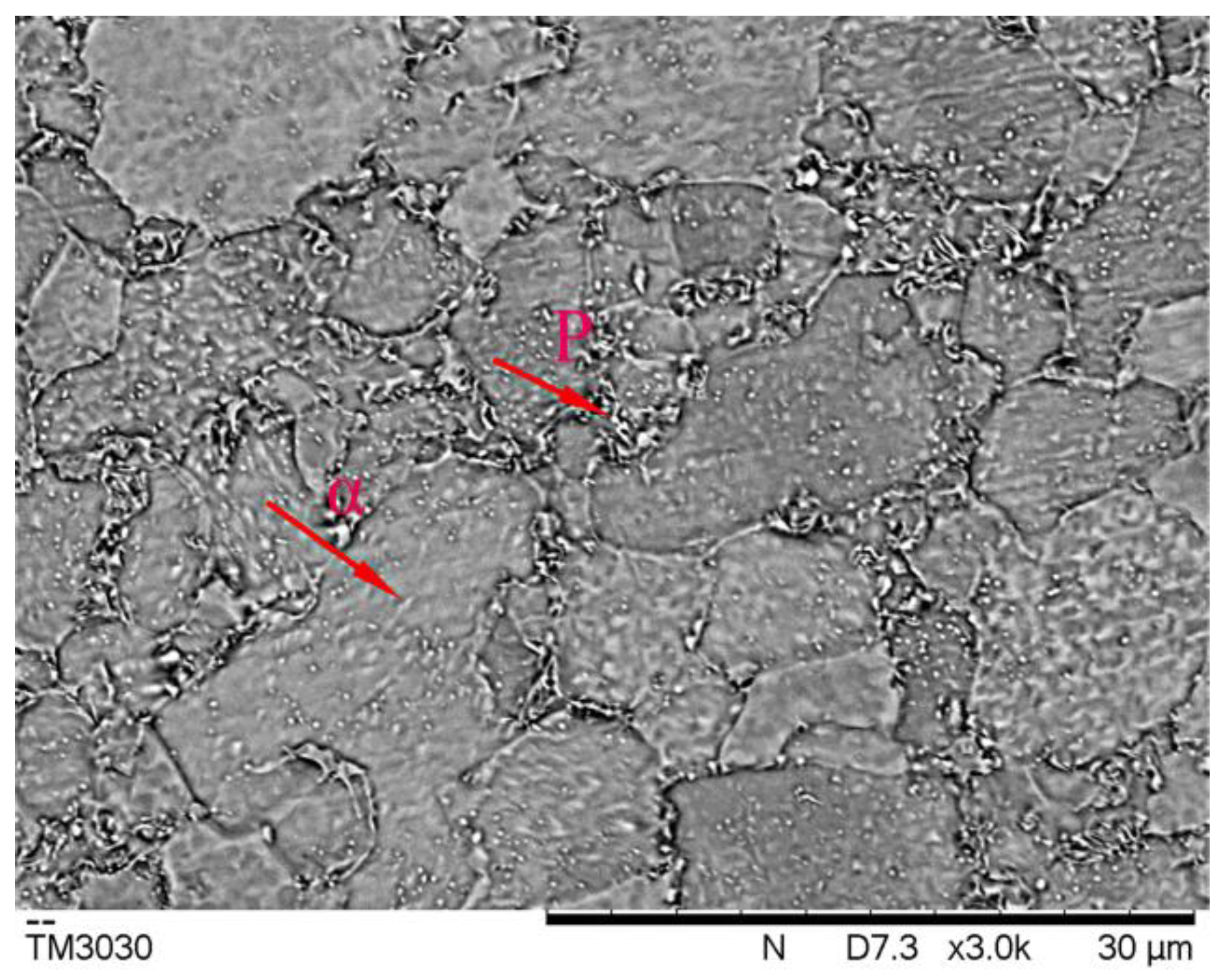
3.1. Phase Transformation Theory of USIBOR® 1500 High-Strength Steel

Phase transformation requires the driving force of phase change, and the resistance of phase transformation and the driving force of phase change affect the general trend of phase transformation. Through a study of the driving force of phase change, the phase equilibrium temperatures of different materials can be determined, thus judging the trend of phase transformation under various temperature conditions. When the driving force of phase transformation is zero, the corresponding temperature is the equilibrium temperature of the phase transformation. The simplified formula of the equilibrium temperature of the phase transformation is 1, 2, 3, and 4 [12]. The content of each element in the formula is the mass percentage.
A e 3   =   1040 453 C   +   33 Si 27 Mn 11 Cr
A e 1 = 730 + 9 Si 11 Mn + 6 Cr ,
B s = 637 58 C 34 Mn 34 Cr ,
M s = 539 423 C 7.5 Si 30 Mn 12.1 Cr ,
where A e 3 is the pre-eutectoid ferrite transformation equilibrium temperature (°C), A e 1 is the pearlite phase transformation equilibrium temperature (°C), B s is the bainite phase transformation equilibrium temperature (°C), and M s is the martensitic phase change equilibrium temperature (°C).
The percentage of each component in Table 1 is substituted into the calculation model of the phase equilibrium transformation temperature, and the initial phase transformation temperature of USIBOR® 1500 high-strength steel is obtained, as shown in Table 2.
Through the study of martensite transformation, the transformation amount of the martensitic microstructure is only influenced by temperature but not by other factors. Therefore, the dynamic expression of the martensitic transformation is as follows [13]:
X = 1 exp [ α ( M s T ) ] ,
where X is change quantity, T is temperature (°C), M s is martensitic transformation temperature (°C), and α is a constant that reflects the rate of martensitic transformation. The α value is 0.02 because of different organizational components.
Table 2 shows that the Ms value of USIBOR® 1500 high-strength steel is 412 °C. In order to study the microstructure transformation of USIBOR® 1500 high-strength steel, the Kirkaldy-Venugopalan model was chosen to be modified to make the model results closer to the dynamic curve of the actual microstructure transformation. The mathematical expressions of the phase transformation model are as follows [14]:
X ˙ = f ( G ) f ( T ) f ( C ) f ( X ) ,
where f ( G ) is the influence factor of austenite grain size, f ( T ) is the influence factor of temperature, and f ( X ) is the influence factor of the production transformation.
f ( G ) = 2 A G ,
where G is austenite grain size, which can assume the value 8, and A is constant.
The austenite grain diameter D is proportional to 2G/2 and share corresponding relationships with different nucleation sites; meanwhile, the influence of austenite grains on the transformation is a mixed effect of these nucleation mechanisms in the process of continuous cold-phase transformation. Therefore, different phase transformations may have varied values. The expression of the influence of temperature is as follows:
f ( T ) = ( T C R T ) n exp ( Q / R T ) ,
where T C R is equilibrium temperature of phase change (K), R is mole constant of gas ( J / k mol ), T is real-time temperature (K), Q is diffusion activation energy ( J / k mol ), and n is constant. When the boundary diffuses, the value is 3. When the volume diffuses, the value is 2.
Mn and Cr in materials affect the diffusion rate of carbon atoms, and the addition of B will prolong the incubation time of ferrite transformation and reduce the ferrite transformation rate [12]. Moreover, the chemical composition of the material has different effects on different phase transformations.
Ferrite transformation:
f ( C ) = ( 59 Mn + 67.7 Cr + 1.9 × 10 5 B ) 1 ,
Transition to pearlite:
f ( C ) = ( 1.79 + 5.42 Cr + 3.1 × 10 3 B ) 1 ,
Bainite transformation:
f ( C ) = ( ( 2.34 + 10.1 C + 3.8 Cr ) × 10 4 ) 1 ,
According to the empirical formula, the influence of the transformation quantity is expressed as follows:
f ( X ) = X 0.40 ( 1 X ) ( 1 X ) 0.40 X ,
According to Zener-Hillert’s model [15], the transformation time and the quantity of transformation are as follows:
τ ( X , T ) = 1 f ( G ) f ( T ) f ( C ) 0 X d X f ( X ) ,
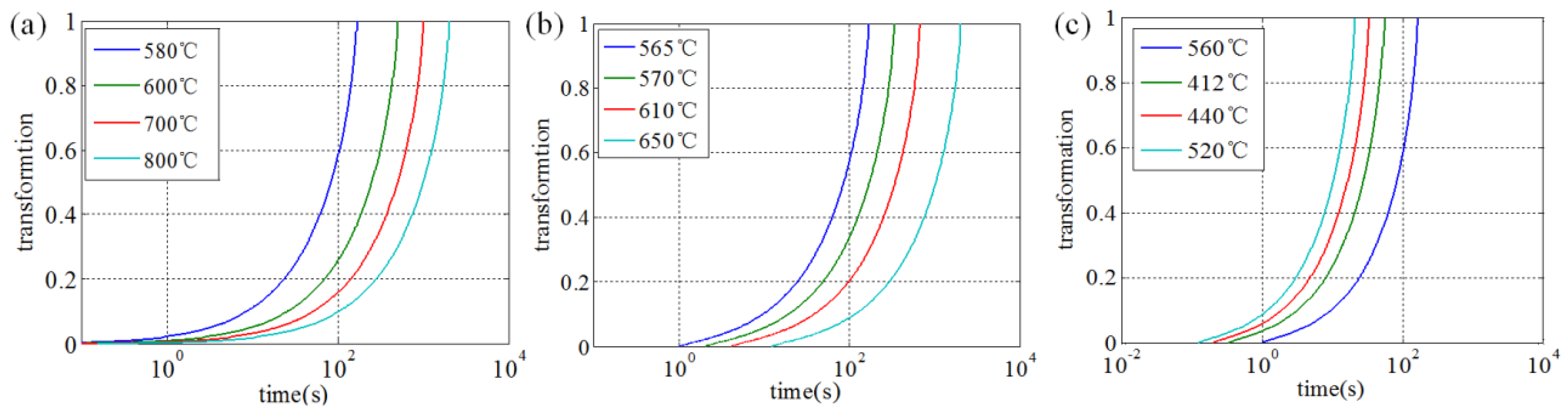
According to the transition temperature range of ferrite, pearlite and bainite, different temperature conditions are selected. Then the parameters are brought into the kinetic model, formula (13), to find the corresponding relationship of the time–transformation quantity under different temperature conditions. The kinetic curves of ferrite, pearlite, and bainite transformation are plotted using MATLAB (version R2016b, MathWorks, Natick, MA, USA).
The above parameters are substituted into the kinetic model, and the kinetic curves of ferrite, pearlite, and bainite transformation are plotted by MATLAB, as shown in Figure 2. The kinetic transformation curves show that the transformation rates of ferrite, pearlite, and bainite are the fastest at 580 °C, 565 °C, and 520 °C, respectively.
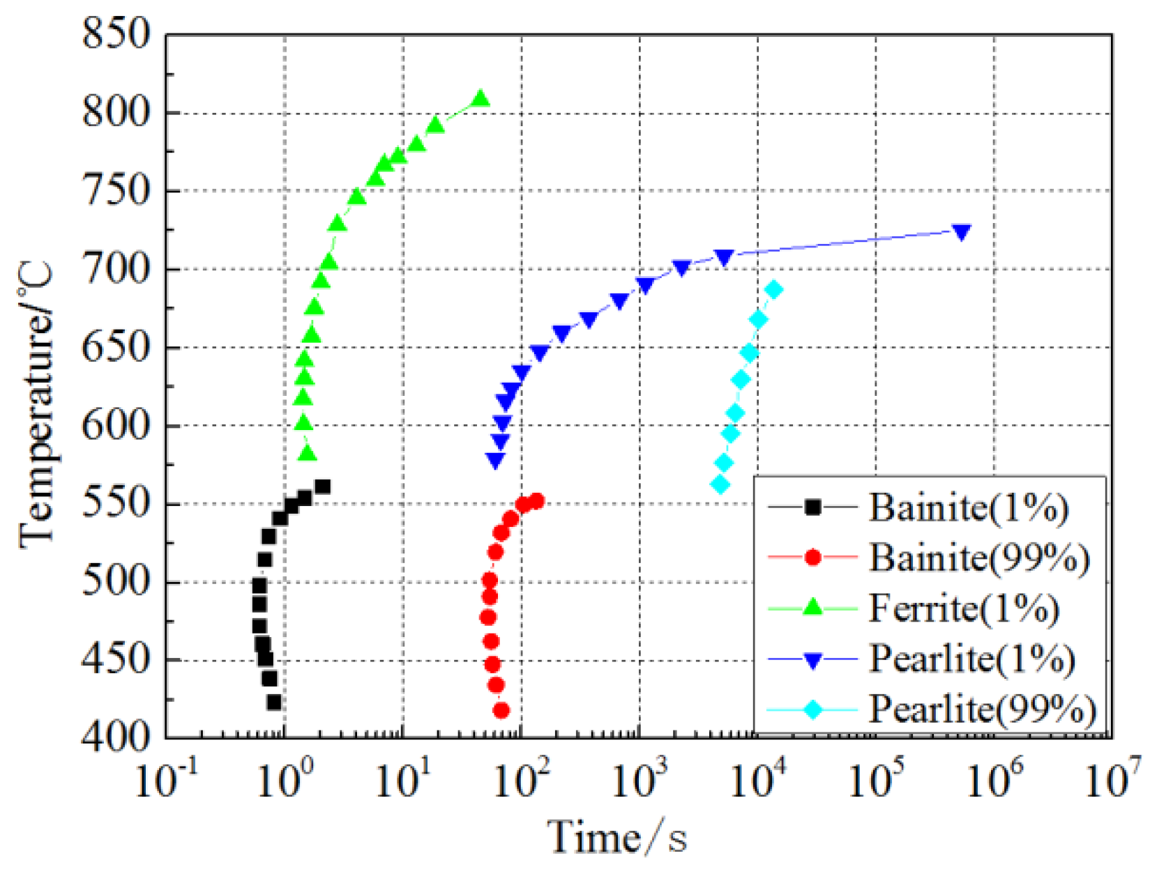
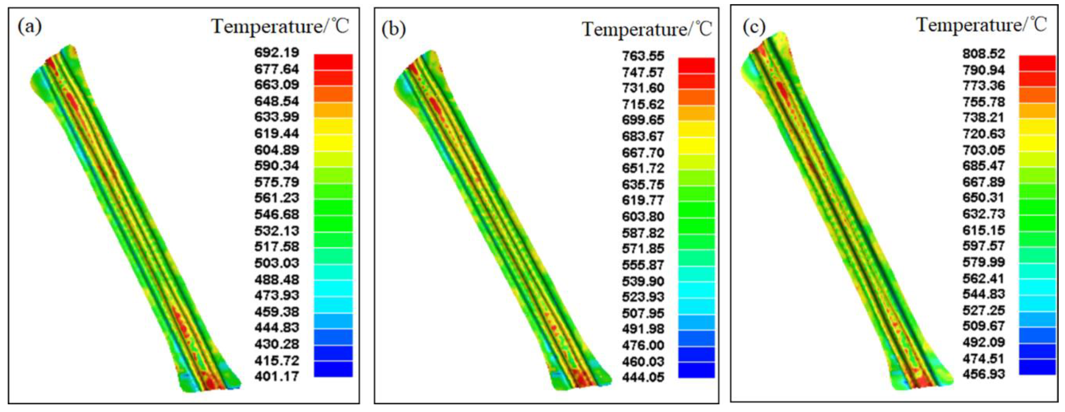
Figure 3 depicts the time-temperature transformation (TTT) curve of USIBOR® 1500 high-strength steel; the curve is created via linear interpolation of the starting point of the dynamic curve phase transformation and the end point of the phase transformation. This curve can be used for predicting the phase transformation law of the quenching process.
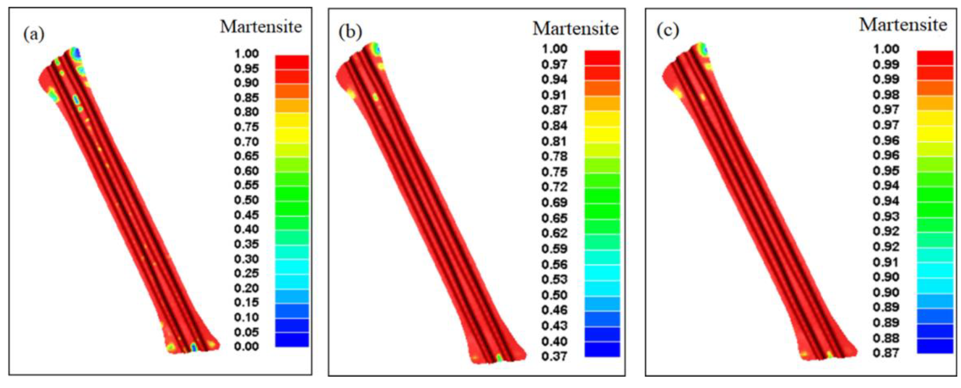
Combined with the CCT curve drawn by Xing [16], in order to ensure the maximum martensite content of the final part, the cooling rate must be kept over 27 °C/s during the pressure-hardening quenching.

3.2. Finite Element Analysis

3.2.1. Finite Element Model and Process Scheme

Figure 4 shows the hot stamping geometry model of a vehicle anti-collision beam. The sheet used is USIBOR® 1500 high-strength steel with a thickness of 1.5 mm. Each component is meshed by DYNAFORM finite element software. The divided grids are mainly quadrilateral and account for 70% of all the grids, and triangle grids account for 30% of the total proportion. The hot stamping process scheme of USIBOR® 1500 high-strength steel is shown in Table 3.

3.2.2. Parameter Design

Table 4 details the specific heat capacity parameter and heat conductivity of USIBOR® 1500 high-strength steel at 20–900 °C [17]. The two parameters mentioned in the Table 4 are the most commonly used parameters in describing the thermodynamic properties of high-strength steel. The parameters of the hot stamping process of high-strength steel vary with temperature; hence, simulation must be conducted according to correct data for ensuring accuracy of the simulation results.
In the simulation analysis of hot stamping forming using DYNAFORM (version 5.9, LSTC/ETA, USA), in order to optimize the simulation effect, the appropriate material model should be selected to characterize the material. Therefore, select *MAT_ELASTIC_VISCOPLASTIC_THREMAL (#106) as the parameter setting model for the simulated material. Each parameter of the material is a variable related to temperature. Table 5 details the different parameters of USIBOR® 1500 high-strength steel with temperature at 20–900 °C [18].
According to the working conditions of hot stamping, high temperature and oxidation resistant materials must be selected. Therefore, 5CrMnMo steel is chosen as the die material. Table 6 shows the thermomechanical properties of the dye material. Table 7 depicts the specific heat capacity and heat conductivity of the dye material under 20–900 °C [19].
In the parameter design of hot stamping simulation, the initial heating temperature of the sheet and the preheating temperature of the dye should be set when the boundary condition parameters of thermal analysis are defined. The preheating temperature of dye is 100 °C, and the initial temperatures of the sheet are 750 °C, 800 °C, and 850 °C, respectively.
The friction coefficient between the sheet and the mold during the hot stamping is set to 0.15. When the dye moves down, touches the sheet, and finally reaches the bottom dead center of the mold, contact and heat transfer must occur between the mold and the sheet. When the initial temperature of the sheet is different, the thermal contact parameters between the sheet and the mold must vary, and the contact parameters at different temperatures can be determined according to known thermodynamic conditions. Table 8 shows the thermal contact parameters at various temperatures.

3.2.3. Temperature Field Distribution

Figure 5a–c show that when the forming is completed, the areas with higher temperature are mainly distributed at both ends of the part and that with lower temperature are distributed on the sidewall. Meanwhile, the highest temperature is not substantially varied, and the difference in the lowest temperature is apparent. The lowest temperatures of the formed parts at the end of processes 1, 2, and 3 are 385.3 °C, 444.1 °C, and 456.9 °C, respectively.

3.2.4. Thickness Distribution

As shown in Figure 6a–c, the smallest thickness of the formed anti-collision beam is at the two sides of the end, whereas the other parts have a more uniform thickness distribution. However, the high temperature causes the material to be softened and the formability weakened. The maximum thinning rates of the sheet at the end of processes 1, 2, and 3 are 18.7%, 26.7%, and 27.3%, respectively. These findings show that the initial temperature of the sheet has a great influence on the thickness of the final formed parts. The higher the initial temperature of the sheet, the greater the effect on the material during the forming process, thus making the thinning of the sheet increasingly evident.

3.2.5. Martensitic Transformation Process in Quenching Process

Figure 7a–c indicates the following. No martensitic structure is found in the larger areas of the formed parts at the end of process 1; no martensitic structure is found in only smaller areas of the formed parts at the end of process 2; the position with less martensite content also reaches 87% after the quenching of process 3. These results indicate that with the increase of the initial temperature of the sheet, the martensite content of the final quenching will increase. When the initial temperature of the sheet reaches 850 °C, the martensite content exceeds 87%, and the sheet meets the requirement of 1500 MPa strength. Thus, the initial selection of the sheet temperature is 850 °C.

4. Conclusions

(1)
A theoretical model for the phase transformation of USIBOR® 1500 high-strength steel was established. The initial phase transformation temperature of the high-strength steel phase was calculated, and the ferrite, pearlite, and bainite transformation kinetic curves and TTT curves were plotted. An analysis of the curves showed that to ensure the martensite content of the final part, the cooling rate of quenching must be kept over 27 °C/s.
(2)
The law of phase transformation of USIBOR® 1500 high-strength steel during hot stamping was studied by a simulation of the phase transformation process of the formed parts. For ensuring enhanced martensite content at the end of the final quenching, the best choice for the initial temperature of the sheet should be 850 °C.

Author Contributions

J.L. and P.Z. conceived and designed the experiments; L.Z. performed the experiments; C.X. analyzed the data; J.L. and P.Z. wrote the paper.

Funding

This research received no external funding.

Conflicts of Interest

The authors declare no conflict of interest.

References

  1. Kuziak, R.; Kawalla, R.; Waengler, S. Advanced high-strength steels for automotive industry: A review. Arch. Civ. Mech. Eng. 2008, 8, 103–117. [Google Scholar] [CrossRef]
  2. Matlock, D.K.; Speer, J.G. Third Generation of AHSS: Microstructure Design Concepts. In Microstructure and Texture in Steels and Other Materials; Haldar, A., Suwas, S., Bhattacharjee, D., Eds.; Springer: Berlin, Germany, 2009; pp. 185–205. [Google Scholar]
  3. Kolleck, R.; Veit, R.; Merklein, M.; Lechler, J.; Geiger, M. Investigation on induction heating for hot stamping of boron alloyed steels. CIRP Ann-Manuf. Technol. 2009, 58, 275–278. [Google Scholar] [CrossRef]
  4. Yao, Y.; Meng, J.P.; Ma, L.Y.; Zhao, G.Q.; Wang, L.R. Study on Hot Stamping and Usibor 1500P. Appl. Mech. Mater. 2013, 320, 419–425. [Google Scholar] [CrossRef]
  5. Liu, W.; Liu, H.S.; Xing, Z.W.; Liu, G. Effect of tool temperature and punch speed on hot stamping of ultra high-strength steel. Trans. Nonferrous Met. Soc. China. 2012, 22, s534–s541. [Google Scholar] [CrossRef]
  6. Quan, G.Z.; Wang, T.; Zhang, L. Research on the influence of hot stamping process parameters on phase field evolution by thermal-mechanical phase coupling finite element. Int. J. Adv. Manuf. Technol. 2016, 89, 1–17. [Google Scholar] [CrossRef]
  7. Zhu, B.; Zhang, Y.; Li, J.; Wang, H.; Ye, Z.C. Simulation research of hot stamping and phase transition of automotive high-strength steel. Mater. Res. Innov. 2011, 15, S426–S430. [Google Scholar] [CrossRef]
  8. Tamas, R.; Zoltan, F.; Imre, F. Computer simulation of steel quenching process using a multi-phase transformation model. Comput. Mater. Sci. 2001, 22, 261–278. [Google Scholar]
  9. Bok, H.H.; Lee, M.G.; Kim, H.D.; Moon, M.B. Thermo-mechanical finite element simulation incorporating the temperature dependent stress-strain response of low alloy steel for practical application to the hot stamped part. Met. Mater.-Int. 2010, 16, 185–195. [Google Scholar] [CrossRef]
  10. Kirkaldy, J.S.; Venugopalan, D. Prediction of microstructure and hardenability in low alloy steels. In Phase Transformation in Ferrous Alloys, Proceedings of an International Conference, Metallurgical Soc of AIME, Ferrous Metallurgy Committee, Warrenda; ASM, Material Science Div: Metals Park, OH, USA, 1984; pp. 125–148. [Google Scholar]
  11. Bok, H.H.; Lee, M.G.; Pavlina, E.J.; Barlat, F.; Kim, H.D. Comparative study of the prediction of microstructure and mechanical properties for a hot-stamped B-pillar reinforcing part. Int. J. Mech. Sci. 2011, 53, 744–752. [Google Scholar] [CrossRef]
  12. Hong, Y.Y. Research on phase transformation and numerical simulation of BR1500HS in hot stamping. Master’s Thesis, Harbin Institute of Technology, Harbin, China, 1 July 2014. [Google Scholar]
  13. Mori, K.; Maki, S.; Tanaka, Y. Warm and hot stamping of ultra high tensile strength steel sheets using resistance heating. CIRP Ann-Manuf. Technol. 2005, 54, 209–212. [Google Scholar] [CrossRef]
  14. Hoffmann, H.; So, H.; Steinbeiss, H. Design of hot Stamping tools with cooling system. CIRP Ann-Manuf. Technol. 2007, 56, 269–272. [Google Scholar] [CrossRef]
  15. Samanta, S.; Biswas, P.; Singh, S.B. Analysis of the kinetics of bainite formation below the M S, temperature. Scr. Mater. 2017, 136, 132–135. [Google Scholar] [CrossRef]
  16. Hong, Y.Y.; Xing, Z.W.; Zhao, H. A model for the prediction of phase transformation of steel BR1500HS. Adv. Commun. Technol. Syst. 2014, 56, 371–378. [Google Scholar]
  17. Åkerström, P.; Bergman, G.; Oldenburg, M. Numerical implementation of a constitutive model for simulation of hot stampin. Model. Simul. Mater. Sci. Eng. 2007, 15, 105–119. [Google Scholar] [CrossRef]
  18. Naderi, M.; Uthaisangsuk, V.; Prahl, U.; Bleck, W. A numerical and experimental investigation into hot stamping of boron alloyed heat treated steels. Steel Res. Int. 2008, 79, 77–84. [Google Scholar] [CrossRef]
  19. Naderi, M.; Durrenberger, L.; Molinari, A.; Black, W. Constitutive relationships for 22MnB5 boron steel deformed isothermally at high temperatures. Mater. Sci. Eng. A-Struct. Mater. Prop. Microstruct. Process. 2008, 478, 130–139. [Google Scholar] [CrossRef]
Figure 1. SEM microstructure of USIBOR® 1500 high-strength steel after rolling and annealing.
Metals 09 01119 g001
Figure 2. Dynamic curves of USIBOR® 1500 high-strength steel; (a) ferrite, (b) pearlite, (c) bainite.
Metals 09 01119 g002
Figure 3. The time-temperature transformation (TTT) curve of USIBOR® 1500 high-strength steel.
Metals 09 01119 g003
Figure 4. 3D model of hot stamping of the vehicle anti-collision beam; 1—female dye, 2—sheet, 3—punch, 4—blank holder.
Metals 09 01119 g004
Figure 5. Temperature field distribution of formed parts at the end of hot stamping; (a) process 1, (b) process 2, and (c) process 3.
Metals 09 01119 g005
Figure 6. Thickness distribution of formed parts at end of hot stamping, (a) process 1, (b) process 2 and (c) process 3.
Metals 09 01119 g006
Figure 7. Martensite content of the formed part at the end of the holding pressure and quenching; (a) process 1, (b) process 2, and (c) process 3.
Metals 09 01119 g007
Table 1. Material composition of USIBOR® 1500 high-strength steel.
ElementsPercentage (wt %)
C0.2220
Mn1.2120
P0.0200
S0.0032
Si0.2590
Al0.0362
Ti0.0386
B0.0038
Cr0.1912
Table 2. Initial phase transformation temperature of USIBOR® 1500 high-strength steel.
Phase A e 3   A e 1   B s   M s  
Phase change initial temperature (°C)824722575412
Table 3. Hot stamping process scheme.
Sheet Temperature (°C)Mould Preheating Temperature (°C)Process Sequence
750100Process 1
800100Process 2
850100Process 3
Table 4. Specific heat capacity and heat conductivity of USIBOR® 1500 at 20–900 °C.
Temperature (°C)20100200300400500700900
Heat conductivity W / ( m K ) 29.530.827.821.6-23.425.3-
Specific heat capacity J / ( kg K ) 4.34.95.15.55.65.75.85.85
Table 5. Material properties of USIBOR® 1500 high-strength steel at 20–900 °C.
Temperature (°C)20100200300400500600700800900
E/GPa211208195192164155151141135125
Poisson’s ratio0.270.270.270.280.280.310.320.320.330.33
Viscous parameters C4.274.224.113.883.843.713.623.453.323.12
Viscous parameters P6.2 × 1098.4 × 1051.4 × 1041.3 × 10325780.241.530.321.331.1
Table 6. Thermomechanical properties of the dye materials.
MaterialDensity kg/m3E/GPaPoisson’s Ratio Specific   Heat   Capacity   J / ( kg K )
5CrMnMo78002100.286382
Table 7. Specific heat capacity and heat conductivity of dye material under 20–900 °C.
Temperature (°C)20100200300400500600700800900
Specific heat capacity J / ( kg K ) 380388417448.6481.8528.6540.2542.2540540
Heat conductivity W / ( m K ) 62.683.384.27467.13-57.68-48.21-
Table 8. Thermal contact parameters at different temperatures.
Temperatures (°C)400600700800900
Thermal emissivity SBC0.0920.0980.1010.1020.113
Heat conductivity W / ( m K ) 72.3270.2371.4571.7072.21

