Article

Simulation Study on Thermo-Mechanical Controlled Process of 800 MPa-Grade Steel for Hydropower Penstocks

1
State Key Laboratory of Metastable Materials Science and Technology, Yanshan University, Qinhuangdao 066004, China
2
National Engineering Research Center for Equipment and Technology of Cold Strip Rolling, Yanshan University, Qinhuangdao 066004, China
*
Author to whom correspondence should be addressed.
Metals 2016, 6(9), 209; https://doi.org/10.3390/met6090209
Submission received: 7 July 2016 / Revised: 23 August 2016 / Accepted: 25 August 2016 / Published: 31 August 2016
(This article belongs to the Special Issue Process-Structure-Property Relationships in Metals)

Abstract

:
The thermo-mechanical controlled process (TMCP) of 800-MPa-grade non-quenched tempered steel used for penstocks was simulated on a Gleeble-3500 thermo-mechanical simulator. The effect of the finish cooling temperature (FCT) which ranged from 350–550 °C on the microstructure and mechanical properties was studied. The microstructure of TMCP specimens is primarily composed of lath bainite (LB) and granular bainite (GB). The decreased FCT can induce the increase of LB and the decrease of GB in the volume fraction, and the decrease in the amount and the size of Martensite/Austenite (M/A) constituents with a more dispersive distribution. The LB has higher strength and hardness than GB, and the GB with fine and dispersive M/A constituents has excellent impact toughness. The minimum values of the yield strength, tensile strength and hardness, and the maximum value of the impact absorbed energy are obtained for the FCT of 450 °C. For the FCT over 450 °C, the yield strength, tensile strength and hardness are increased slightly, but the impact absorbed energy is rapidly decreased, which is mainly attributed to the formation of block M/A constituents. When the FCT is around 400 °C, the optimal combination of yield strength and impact toughness is obtained, which meets the technical requirements of 800-MPa-grade hydropower penstock steel.

Graphical Abstract

1. Introduction

A higher water head and larger capacities are required for the scale merits of hydropower plants, which make penstocks bear larger pressure. This requires the penstock steel to have a higher strength level, as well as sufficient toughness and excellent weldability. At present, 600-MPa-grade steel used for hydropower penstocks is mostly delivered in a quenched and tempered condition, little is delivered in the thermo-mechanical controlled process (TMCP) or TMCP+ tempering condition. Steel with an 800-MPa-grade used for hydropower penstocks is delivered only in quenched and tempered condition. Therefore, the development of TMCP of an 800-MPa-grade steel sheet used for hydropower penstocks is significant.
TMCP can bring about various advantages, such as the decrease of the weld pre-heating temperature and heat input due to the decrease of the carbon equivalent value, the improvement of the low temperature toughness, the reduction of the manufacturing cost, and the shortening of the delivery time of steel products [1]; otherwise, TMCP can enable high strength and toughness to be realized throughout the thickness through the control of the austenite grain size [2]. As the production process for the non-quenched tempered steel, TMCP includes controlled rolling and controlled cooling. The controlled cooling is the key to governing the mechanical properties. The cooling rate and finish cooling temperature (FCT) are two important parameters of controlled cooling which have been investigated by some researchers. Ai et al. (2005) [3] studied the TMCP of a 60Si2MnA spring steel rod, showing that increasing the cooling rate can reduce the interlamellar spacing of pearlite and increase the strength. Rasouli et al. (2008) [4] indicated that a faster cooling rate results in a higher strength and lower elongation in medium-carbon non-quenched tempered steel. Yi et al. (2014) [5] reported that interphase precipitation and diffusion precipitation can be observed at different FCTs in Nb-Ti micro-alloyed steel. A higher FCT induces the interphase precipitation, while a lower FCT induces the diffusion precipitation. The interphase precipitation has a larger contribution to enhancing the yield strength than the diffusion precipitation does.
Some studies [6,7] indicated that the yield strength and low temperature toughness can be improved by adding nickel above 1.4 wt %, which increases the cost. For thick plates and higher yield strength grades, a tempering process was usually used after controlled cooling [8], which reduces the production efficiency and increases the costs. Xie et al. (2014) [9] reported that a novel 1000-MPa-grade low-carbon microalloyed steel plate (0.08–0.11 wt % C) can be produced by TMCP at a high cooling rate and low FCT in the absence of a tempering process. The thickness of the TMCP steel plate is only 6 mm because of the large rolling reduction, and the Charpy V-notch impact absorbed energy at −20 °C tested using one-fourth-size specimens (2.5 × 10 × 55 mm3) is 24 J. This is suggested that if the strength is moderately depressed by decreasing the cooling rate, the impact absorbed energy will be further increased. Therefore, the Charpy V-notch impact absorbed energy at −20 °C for the standard specimen could be inferred to be more than 47 J which is required for the 800-MPa-grade hydropower penstocks.
In this study, the TMCP of the 800-MPa-grade non-quenched tempered steel used for hydropower penstocks was simulated on a Gleeble-3500 thermo-mechanical simulator. The aim is to study the influence of a wider range of FCTs on the microstructure and mechanical properties to optimize the FCT for the TMCP of the steel.

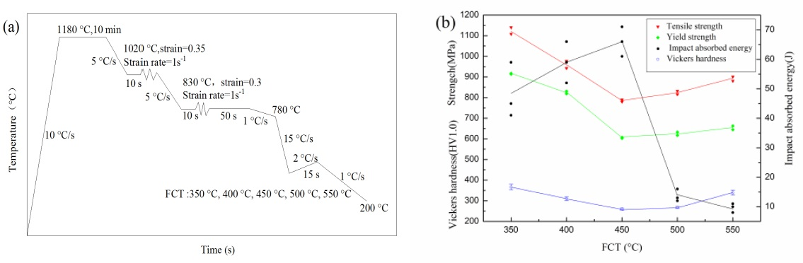
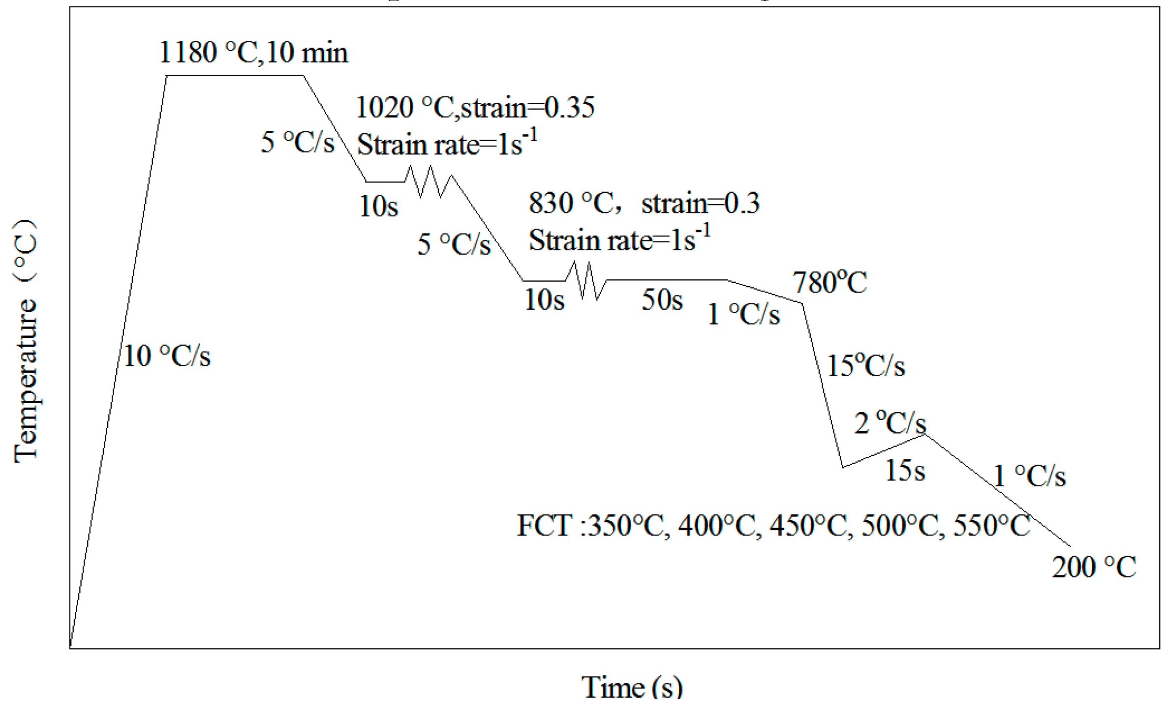
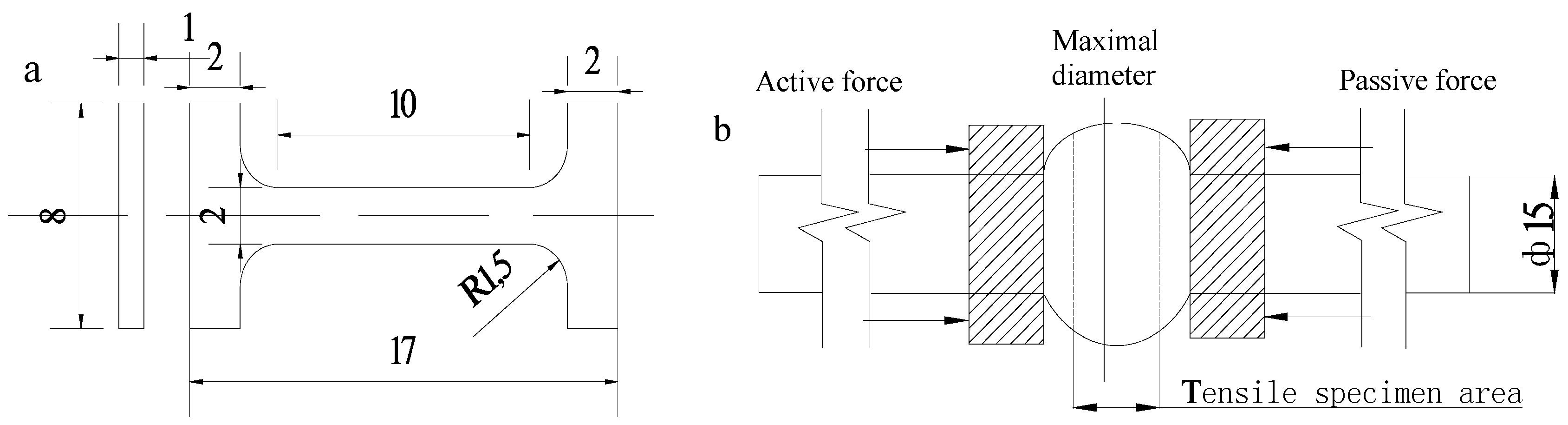
2. Materials and Methods

The hot-rolled steel plate with thickness of 60 mm was used in the present study. The chemical composition is listed in Table 1.
TMCP simulation was performed on Gleeble-3500 thermo-mechanical simulator (DSI, Saint Paul, MN, USA) using round bar specimens with a length of 75 mm and diameter of 15 mm sampled from the one-fourth-thickness of the hot-rolled steel plate. The TMCP regimes are given in Figure 1. The compressive deformation includes two steps, “roughing” and “finishing”, those were respectively performed at 1020 °C (γ recrystallization region) and 830 °C (γ non-recrystallization region). Accelerated cooling (ACC) was started at 780 °C with a cooling rate of 15 °C/s and interrupted at different FCTs, and then the specimen was reheated with 2 °C/s for 15 s to simulate self-tempering schedule, and then cooled with 1 °C/s to simulate air cooling.
The microstructure of the simulated TMCP specimens was examined at the central area in the longitudinal section by optical microscopy (OM, Axiover-200MAT, Zeiss, Heidenheim, Germany) and transmission electron microscopy (TEM, JEM-2010, JEOL, Musashino, Japan). Specimens for OM were mechanically ground, polished and etched with 4% nital. For TEM examination, ~0.6 mm-thick foils were cut via wire electro-discharging and ground to ~30 μm in thickness using waterproof abrasive paper, and then thinned to perforation on a TenuPol-5 twinjet electro-polishing device (Struers, Ballerup, Denmark) using an electrolyte composed of 7% perchloric acid and 93% glacial acetic acid solution at room temperature and a voltage of 28 V.
For the simulated TMCP specimens, the tensile property and hardness were measured at room-temperature, and the Charpy V-notch impact toughness was evaluated at −20 °C. Because of the limitation of the simulated specimen size, the sub-size tensile specimens was used to measure the tensile properties. Chu et al. (2000) [10] have experimentally demonstrated that there is no much difference in strength between sub-size tensile specimen and standard specimen. The dimensions of the sub-size specimens used in this work are shown in Figure 2a, which were given by Fan et al. (2014) [11]. The tensile specimens were wire-cut from the TMCP simulated specimens (Figure 2b). The tensile property was measured on a tensile testing machine (INSPEK TABLE100, Hegewald&Peschke, Nossen, Germany) with a cross-head speed of 0.25 mm/min. The impact absorbed energy was measured at −20 °C on an impact testing machine (JBN-300B 150 J, Shidaizhifeng, Beijing, China) using standard Charpy V-notch specimens with sizes of 10 × 10 × 55 mm3. Because the incompletely symmetrical deformation was induced by compressive deformation in TMCP simulation due to the active force applied on one side of the specimen, the notch of the impact specimens were machined at the maximal diameter of simulated TMCP specimens. Additionally, the impact fracture surface was examined on a scanning electron microscope (SEM, Hitachi S-3400, Hitachi, Tokyo, Japan). The Vickers hardness of the specimens was measured on a micro-Vickers hardness tester (FM-ARS9000, Future Tech, Kanagawa, Japan) with a load of 9.8 N.

3. Results and Discussion

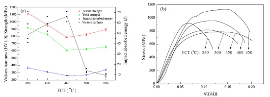
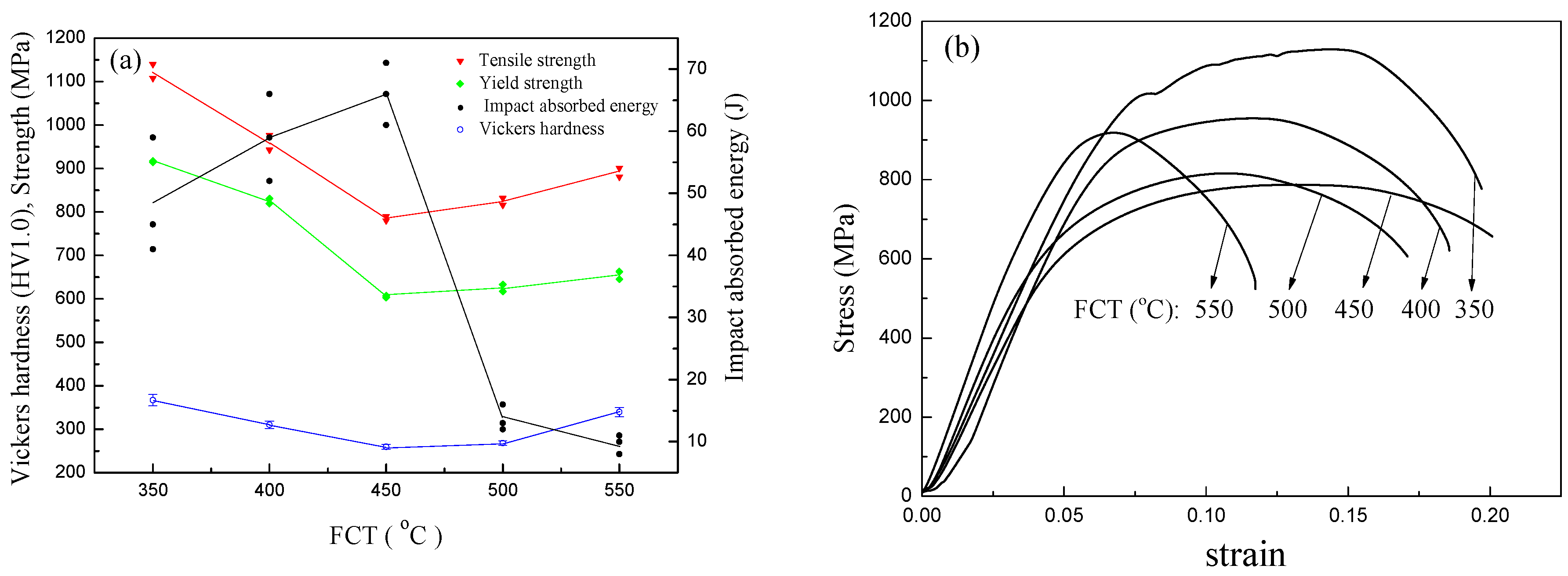
3.1. Effect of FCT on Mechanical Properties

Figure 3a gives the influence of the FCT on the mechanical properties of the simulated TMCP specimens, and Figure 3b shown the stress-strain curves of the specimens under tensile testing. It is indicated that with the FCT increasing, both the strength and hardness decrease first and then slightly increase, and the minimum is obtained at a FCT of 450 °C. When the FCTs are 350 °C and 400 °C, the yield strength exceeds 800 MPa. The effect of the FCT on the impact absorbed energy (−20 °C) is opposed to that on the strength and hardness (Figure 3a); the impact absorbed energy increases first and then decreases with the FCT increasing. The maximum impact absorbed energy occurs at a FCT of 450 °C, and the impact absorbed energy rapidly decreases when the FCT is above 450 °C. When the FCT is 400 °C and 450 °C, the measured values of the impact absorbed energy are much more than 47 J. In addition, from Figure 3b one can see that the tensile elongation is below 15% only at the FCT of 550 °C. Therefore, the optimized FCT for 800-MPa-grade hydropower penstock steel could be around 400 °C, which results in the room-temperature yield strength of 820–830 MPa and the −20 °C impact absorbed energy of 52–66 J.
The SEM morphologies of the impact fracture surfaces of the simulated TMCP specimens are shown in Figure 4. For the specimens with a FCT not above 450 °C, one can observe small cleavage facets, tear ridges, and some dimples in the fracture surface (Figure 4a–c), which absorb more impact energy. However, for the specimens with a FCT above 450 °C (such as 500 °C and 550 °C), many large cleavage facets were observed in the fracture (Figure 4d,e), which absorb less impact energy.

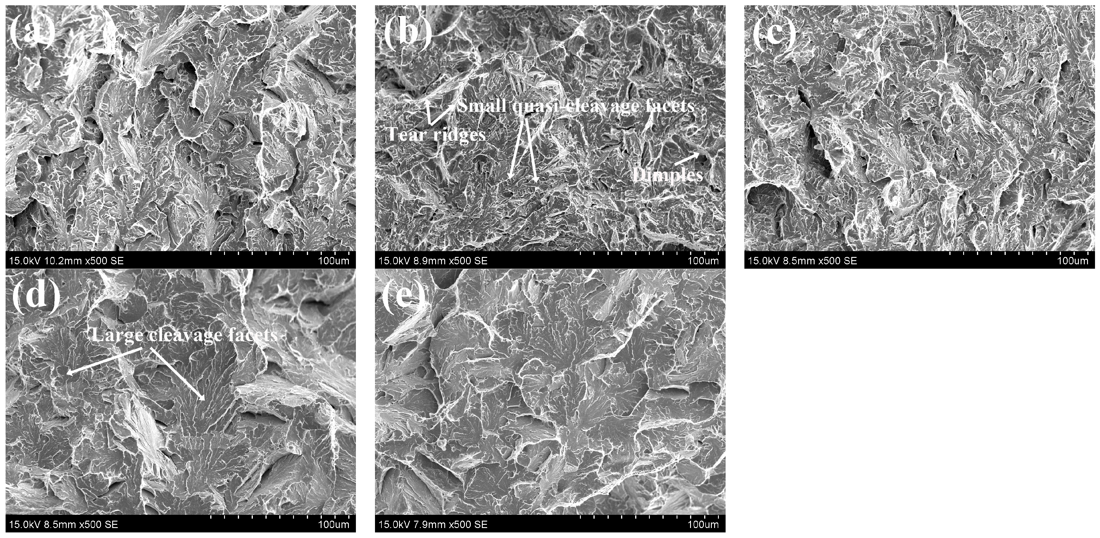
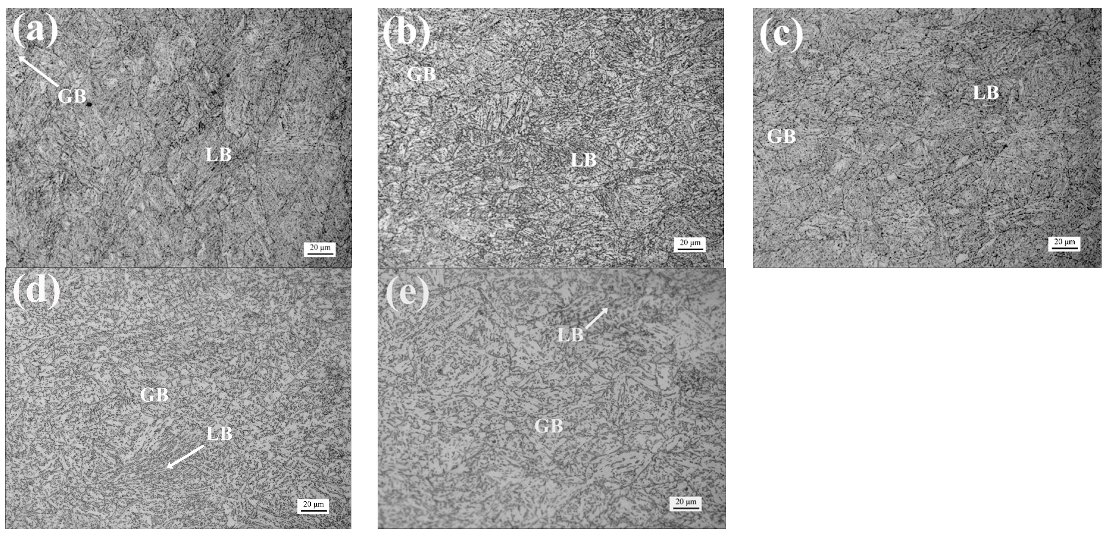
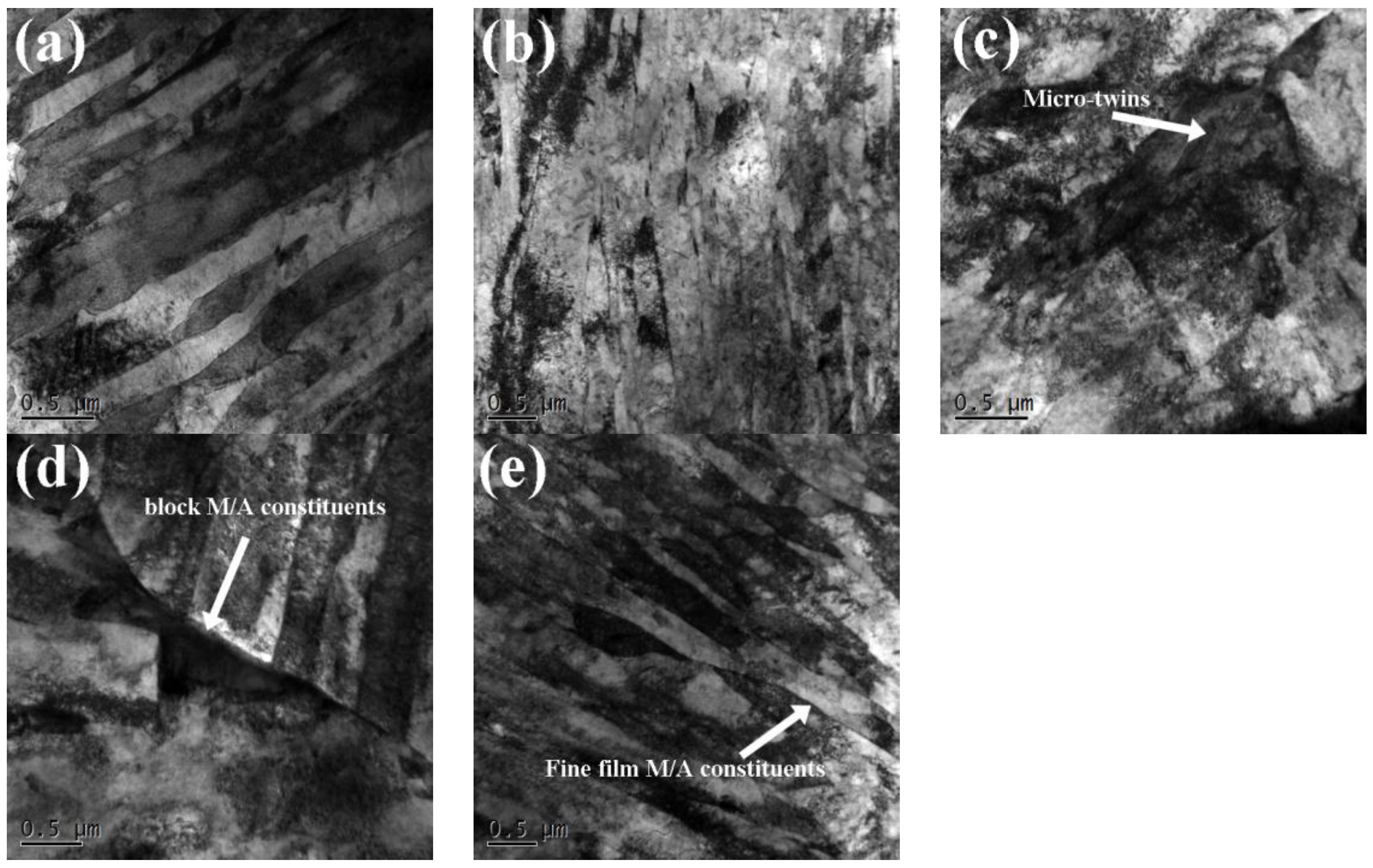
3.2. Relationship between Microstructure and Mechanical Properties

Optical microscopy (OM) microstructures in specimens after simulated TMCP with FCTs of 350 °C, 400 °C, 450 °C, 500 °C, and 550 °C are illustrated in Figure 5a–e, respectively. It can be seen that the microstructures of all TMCP specimens are primarily composed of lath bainite (LB) and granular bainite (GB). The LB is a fine lamella structure, and the GB is some island constituents distributed in the matrix. The volume fractions of LB and GB were roughly evaluated, as shown in Table 2, indicating that as the FCT increases, the fraction of GB increases, but LB decreases. Usually, a slower cooling rate promotes the formation of GB, while a faster cooling rate promotes the formation of LB. The increased FCT is equivalent to the decrease in the undercooling degree or cooling rate, which promotes the formation of GB.
In order to observe the details of the microstructures, TEM examinations were performed for two TMCP specimens with FCTs of 550 °C and 350 °C, the former mainly composed of GB and the latter mainly composed of LB (see Table 2). Figure 6a–d show the TEM micrographs of GB in the specimen after simulated TMCP with a FCT of 550 °C, displaying the lath-like morphology. This is similar to what was observed by Luo et al. (2010) [12] and Zhao et al. (2016) [13] through TEM; that is, the GB was composed of bainitic ferrite lath and islands of austenite and martensite (M/A constituents) which are transformed from austenite during the accelerated cooling processes. Figure 6a,b show two kinds of GB, i.e., bainitic ferrite laths with clear and unclear boundaries. The unclear lath boundaries could be caused by the recovery of GB formed at a higher temperature, which can be indirectly proved by the fact that the fine rod-like carbides precipitated inside laths can be detected (Figure 6b). Additionally, one can also observe M/A constituents with micro-twins in martensite (Figure 6c) and the blocky M/A constituents in prior austenite boundaries (Figure 6d).
Figure 6e shows the TEM micrographs of LB in the specimen after the simulated TMCP with a FCT of 350 °C, displaying the lath-like morphology, i.e., LB. The dislocation density in LB is higher than that in GB; meanwhile, film-like M/A constituents are located in between the laths, which could be attributed to the relatively faster cooling rate that promotes the formation of LB. These differences between LB and GB can result in the difference in mechanical properties. It is well-known that the LB can make a greater contribution to strength and hardness than GB does. Therefore, the highest strength and hardness were obtained in the specimen after TMCP with a FCT of 350 °C. The increase in the FCT results in the increase in the volume fraction of GB, which leads to the decrease in the strength and hardness. When the FCT increases to 450 °C, the microstructure is composed of 81 vol % GB and 19 vol % LB (Table 2), obtaining the lowest strength and hardness. A further increase in the FCT induces the slight increase in strength and hardness, which could result from the dispersion strengthening of fine precipitates (Figure 6b) and the large-sized M/A constituents (Figure 6c,d).
When the FCTs are high (500 °C and 550 °C), the impact absorbed energy is only about 10 J, which is attributed to the block of the M/A constituents (Figure 6c,d) in the microstructure. The brittle block M/A constituents distributed on the grain boundaries are usually regarded as the site of the crack initiation and deteriorate the impact toughness [14]. When the FCT decreases to 450 °C, the impact absorbed energy increases rapidly, which results from the lower FCT (equivalent to a faster cooling rate) making the amount and the size of M/A constituents decrease and its form changes to dot-like; meanwhile, the M/A constituents distribute more dispersively [14,15]. The fine and dispersive M/A constituents can effectively prevent crack propagation [15,16]. When the FCT decreases from 450 °C to 350 °C, the amount of M/A constituents further decreases and its form changes to film-like (Figure 6e), and the microstructure is mainly composed of LB (see Table 2). Although LB with a low-angle grain boundary has little effect for inhibiting crack propagation [14], the film-like M/A constituents between bainitic laths strongly prevent dislocation motion and crack propagation [17], and thus the impact absorbed energy does not decrease markedly.

4. Conclusions

As the FCT decreases from 550 °C to 350 °C, mechanical properties of simulated TMCP specimens are non-monotonic functions of the FCT. The minimum values of the yield and tensile strength and hardness and the maximum value of the impact absorbed energy are obtained at the FCT of 450 °C. The microstructures in the simulated TMCP specimens are primarily composed of LB and GB. The decrease in the FCT can result in the increase in the volume fraction of LB and the decrease in the volume fraction of GB, and the decrease in the amount and the size of M/A constituents with more dispersive distribution. The optimum FCT of the TMCP for the steel is around 400 °C, which results in the room-temperature yield strength of 820–830 MPa and the −20 °C impact absorbed energy of 52–66 J, which meets the technical requirements of 800-MPa-grade hydropower penstock steel.

Acknowledgments

This work was supported by the National Natural Science Foundation of China (Grant No. 51471147).

Author Contributions

Tiansheng Wang designed the experiments and wrote the paper; Qingfeng Ding and Yuefeng Wang performed the experiments, analyzed the data and wrote the paper, Qingfeng Wang performed the experiments and analyzed the data.

Conflicts of Interest

The authors declare no conflict of interest.

References

  1. Chiaki, O. Development of Steel Plates by Intensive Use of TMCP and Direct Quenching Processes. ISIJ Int. 2001, 41, 542–553. [Google Scholar]
  2. Nishiokaand, K.; Ichikawa, K. Progress in thermo-mechanical control of steel plates and their commercialization. Sci. Technol. Adv. Mater. 2012, 13, 1–20. [Google Scholar]
  3. Ai, J.H.; Zhao, T.C.; Gao, H.J.; Hu, Y.H.; Xie, X.S. Effect of controlled rolling and cooling on the microstructure and mechanical properties of 60Si2MnA spring steel rod. J. Mater. Process. Technol. 2005, 160, 390–395. [Google Scholar] [CrossRef]
  4. Rasouli, D.; Asl, S.K.; Akbarzadeh, A.; Daneshi, G.H. Effect of cooling rate on the microstructure and mechanical properties of microalloyed forging steel. J. Mater. Process. Technol. 2008, 206, 92–98. [Google Scholar] [CrossRef]
  5. Yi, H.L.; Yang, X.; Sun, M.X.; Liu, Z.Y.; Wang, G.D. Influence of finishing cooling temperature and holding time on nanometer-size carbide of Nb-Ti microalloyed steel. J. Iron Steel Res. Int. 2014, 21, 433–438. [Google Scholar] [CrossRef]
  6. Onishi, K.; Katsumoto, H.; Kamo, T.; Sakaibori, H.; Kawabata, T.; FujiwAra, K.; Okaguchi, S. Study on application of advanced TMCP to high tensile strength steel plates for penstock. Weld World 2008, 52, 523–530. [Google Scholar]
  7. Tsuzuki, T.; Kawabata, N.; Okushima, M.; Tokunoh, K.; Okamura, Y. Development and Application of 950MPa and 780MPa Class High Strength Steel for Penstock. In Proceedings of the High Strength Steels for Hydropower Plants, Takasaki, Japan, 20–22 July 2009.
  8. Falko, S. Structural steel for the application in offshore, wind and hydro energy production: Comparison of application and welding properties of frequently used materials. Int. J. Microstruct. Mater. Prop. 2011, 6, 4–19. [Google Scholar]
  9. Xie, H.; Du, L.X.; Hu, J.; Misra, R.D.K. Microstructure and mechanical properties of a novel 1000 MPa grade TMCP low carbon microalloyed steel with combination of high strength and excellent toughness. Mater. Sci. Eng. A 2014, 612, 123–130. [Google Scholar] [CrossRef]
  10. Chu, R.Q.; Duan, Z.Q.; Dong, H.; Yang, K.; Li, S.X.; Wang, Z.G. Design of a kind of mini-tensile-specimen and its application in research of the high-performance pipe line steel. Acta Metall. Sin. 2000, 36, 626–629. [Google Scholar]
  11. Fan, L.; Wang, T.L.; Fu, Z.B.; Zhang, S.M.; Wang, Q.F. Effect of heat-treatment on-line process temperature on the microstructure and tensile properties of a low carbon Nb-microalloyed steel. Mater. Sci. Eng. A 2014, 607, 559–568. [Google Scholar] [CrossRef]
  12. Luo, Y.; Peng, J.M.; Wang, H.B.; Wu, X.C. Effect of tempering on microstructure and mechanical properties of a non-quenched bainitic steel. Mater. Sci. Eng. A 2010, 527, 3433–3437. [Google Scholar] [CrossRef]
  13. Zhao, Z.P.; Qiao, G.Y.; Tang, L.; Zhu, H.W.; Liao, B.; Xiao, F.R. Fatigue properties of X80 pipeline steels with ferrite/bainite dual-phase microstructure. Mater. Sci. Eng. A 2016, 657, 96–103. [Google Scholar] [CrossRef]
  14. Chen, X.W.; Qiao, G.Y.; Han, X.L.; Wang, X.; Xiao, F.R.; Liao, B. Effects of Mo, Cr and Nb on microstructure and mechanical properties of heat affected zone for Nb-bearing X80 pipeline steels. Mater. Des. 2014, 53, 888–901. [Google Scholar] [CrossRef]
  15. Wang, C.M.; Wu, X.F.; Liu, J.; Xu, N.A. Transmission electron microscopy of martensite/austenite islands in pipeline steel X70. Mater. Sci. Eng. A 2006, 438–440, 267–271. [Google Scholar] [CrossRef]
  16. Sung, H.K.; Lee, S.H.; Shin, S.Y. Effects of Start and Finish Cooling Temperatures on Microstructure and Mechanical Properties of Low-Carbon High-Strength and Low-Yield Ratio Bainitic Steels. Metall. Mater. Trans. A 2013, 45, 2004–2013. [Google Scholar] [CrossRef]
  17. Zhong, Y.; Xiao, F.R.; Zhang, J.W.; Shan, Y.Y.; Wang, W.; Yang, K. In situ TEM study of the effect of M/A films at grain boundaries on crack propagation in an ultra-fine acicular ferrite pipeline steel. Acta Mater. 2006, 54, 435–443. [Google Scholar] [CrossRef]
Figure 1. Process curve of simulated TMCP.
Metals 06 00209 g001
Figure 2. (a) Dimensions of tensile specimens cut from the center of the compressive deformation specimens along transversal direction; (b) Dimensions of specimens after simulated TMCP.
Metals 06 00209 g002
Figure 3. (a) Relationships between mechanical properties (tensile strength, yield strength, impact absorbed energy, and hardness) and FCT; (b) Engineering stress-strain curves.
Metals 06 00209 g003
Figure 4. SEM morphologies of impact fracture of specimens after TMCP with different FCTs: (a) 350 °C; (b) 400 °C; (c) 450 °C; (d) 500 °C; (e) 550 °C.
Metals 06 00209 g004
Figure 5. OM micrographs of specimens after TMCP with different FCTs: (a) 350 °C; (b) 400 °C; (c) 450 °C; (d) 500 °C; (e) 550 °C.
Metals 06 00209 g005
Figure 6. TEM micrographs of specimens after TMCP with FCT of 550 °C (ad) and 350 °C (e).
Metals 06 00209 g006
Table 1. Chemical compositions of test steel (wt %).
CMnSiCuNiCrMoNbVTiBCeq
0.091.500.300.200.500.400.250.0250.0450.0130.00110.52
Note: Ceq = C + Mn/6 + (Cr + Mo + V)/5 + (Ni + Cu)/15(%).
Table 2. Volume fractions of LB and GB in TMCP specimens with different FCTs.
FCT (°C)350400450500550
LB(vol %)92 ± 660 ± 519 ± 58 ± 46 ± 3
GB(vol %)8 ± 640 ± 581 ± 592 ± 494 ± 3

