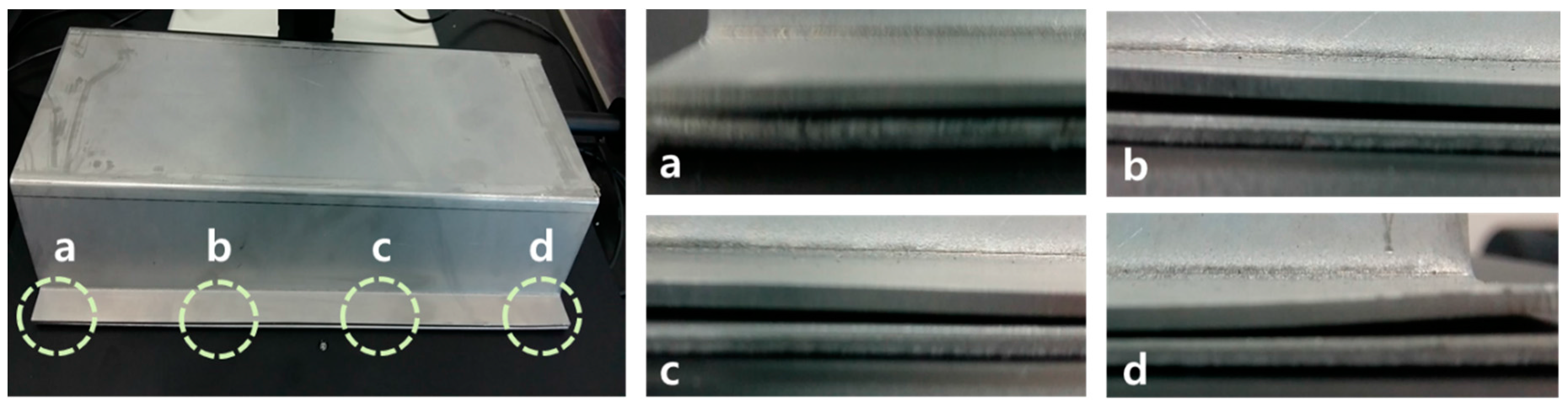
Article

The Effects of Laser Welding Direction on Joint Quality for Non-Uniform Part-to-Part Gaps

1
Smart Factory Laboratory, Ulsan National Institute of Science and Technology, UNIST-gil 50, Ulsan 44919, Korea
2
Warwick Manufacturing Group, University of Warwick, Coventry CV4 7AL, UK
*
Author to whom correspondence should be addressed.
Metals 2016, 6(8), 184; https://doi.org/10.3390/met6080184
Submission received: 25 May 2016 / Revised: 2 August 2016 / Accepted: 3 August 2016 / Published: 6 August 2016

Abstract

:
Controlling part-to-part gaps is a crucial task in the laser welding of galvanized steel sheets for ensuring the quality of the assembly joint. However, part-to-part gaps are frequently non-uniform. Hence, elevations and depressions from the perspective of the heading direction of the laser beam always exist throughout the gap, creating ascending, descending, and flat travelling paths for laser welding. In this study, assuming non-uniform part-to-part gaps, the effects of welding direction on the quality of the joint of galvanized steel sheets—SGARC440 (lower part) and SGAFC590DP (upper part)—were examined using 2-kW fiber and 6.6-kW disk laser welding systems. The experimental analysis of coupon tests confirmed that there is no statistically significant correlation between the direction of welding and weld pool quality if the gap exceeds the tolerable range. However, when the gap is controlled within the tolerable range, the welding direction can be considered as an important process control variable to enhance the quality of the joint.

Graphical Abstract

1. Introduction

From the perspective of automotive body-in-white assemblies, laser welding has many desirable features such as high joining speed, excellent repeatability, and non-contact single-sided access, resulting in a greater degree of freedom in car body design. Nevertheless, laser welding is yet to be widely and successfully used, especially for joining of complex galvanized steel parts in lap-joint configurations [1], for which conventional joining methods such as resistance spot welding are generally employed.
Important design parameters for laser welding have been investigated in many empirical studies. For example, Benyounis et al. [2] identified the importance of laser power, focal position, and welding speed on the assembly joint’s quality such as heat input and weld bead geometry (i.e., penetration depth, widths of welded zone, and heat-affected zone). Wu et al. [3] also confirmed that there is a statistically significant correlation between a joint’s quality (i.e., welding penetration and the width of a weld seam) and laser power and welding speed.
In general, individual part variations caused by the deformation of metal sheets result in unexpected gaps between the upper (top) and lower (bottom) parts, as shown in Figure 1. Hence, tight part-to-part gap control is required to ensure the assembly joint quality of the galvanized steel sheets; these sheets are characterized by the lower evaporation point of Zn (906 °C) than the melting point of Fe (1538 °C). The vaporized zinc gas hampers the formation of stabilized keyholes and often causes serious weld defects such as porosity, spatter, intermetallic brittle phases, and discontinuities formed by zinc vapor entrapment in the welding joints [4].
Several ad hoc methods have been developed to control part-to-part gaps; these methods include laser dimpling [5], shim insertion between parts [6], usage of porous powder metal, pre-drilling [7], and synchronous rolling technique [8]. Laser dimpling allows us to create small dimples on bottom parts by using a relatively low-powered laser beam prior to the corresponding laser-welding process. Laser dimpling is a commonly used practical method to realize the minimum required gap because small dimples are created by the same laser system that is used for laser welding [5]. Table 1 summarizes the recent research efforts to identify the major welding parameters that affect the quality of laser lap welding of galvanized steel.
What makes laser welding more complex is that part-to-part gaps are very often non-uniform, as shown in Figure 1. Owing to the non-uniformity, elevation and depression angles always exist throughout the gap, creating ascending, descending, and flat travelling paths for laser welding from the perspective of the direction of the laser beam.
This study examined the effect of the non-uniformity of the part-to-part gap on the weldment quality of a joint during the laser welding of galvanized steel sheets. We conducted an experimental analysis of 84 coupon tests under the in-tolerance condition of part-to-part gap (0.3 mm) and 66 coupon tests under the out-of-tolerance condition (0.5 mm). Laser lap joining of two different galvanized steel sheets, namely, SGARC440 (lower part) and SGAFC590DP (upper part) were performed by using 2-kW fiber and 6.6-kW disk laser welding systems.
The quality characteristic of a weldment was evaluated based on the top and bottom s-values and concavities of the weld pool, and their correlation with the weld direction was examined based on the analysis of variance (ANOVA).
The purpose of the experiment was to examine whether the laser welding direction is as an important process control variable for non-uniform part-to-part gaps, especially in the case of the remote laser welding system with a scanning mirror head used as the end-effector (e.g., Comau’s Smart Laser™). Note that a robotic remote laser welding system can easily change not only the welding position, but also the direction of welding, simply by controlling the tilting mirrors in the scan head, as shown in the Figure 2. This control procedure for repositioning and redirection does not affect the required cycle time of the weld process.

2. The Experiments

2.1. Laser Welding Systems

In order to provide reliable empirical evidence, we conducted coupon tests by using two different laser welding systems, namely, a 2-kW fiber laser welding system and a 6.6-kW disk laser welding system. The former system is a 2.5 axis gantry-based automated welding system that delivers a laser beam from IPG YLS-2000-AC fiber laser source (IPG Photonics, Oxford, MA, USA) with a maximum output discharge of 2 kW in the TEM01 mode of laser radiation. The 6.6-kW disk laser welding system is a five-axis KUKA robot-based remote laser welding system that delivers a laser beam from TRUMPF TruDisk 6602 disk laser (TRUMPF, Schramberg, Germany). Table 2 lists the technical parameters of both systems.

2.2. Experimental Materials

We conducted laser welding experiments using sheets made of galvanized steels SGARC440 (lower part: 1.8 mm thickness) and SGAFC590DP (upper part: 1.4 mm thickness); these materials are currently used in the side-member parts of a car model. The amount of zinc coating on the lower and upper parts and their chemical compositions are summarized in Table 3. The mechanical properties of the tested materials are listed in Table 4.

2.3. Non-Uniform Part-to-Part Gap

In general, for the successful laser welding of galvanized steel, it is necessary first to control the gap usually to be within 10% of the thickness of the upper part on which the laser beam is incident and additionally to allow for the minimum gap between the parts in order to provide a channel to vent out the vaporized zinc [13]. In general, in the case of automotive body parts, gaps of a maximum of 0.3 mm and minimum of 0.05 mm are required for laser welding of galvanized steel sheets.
As shown in Figure 1, these gaps are very often non-uniform because of individual part variations in the galvanized steel sheets. In order to simplify these random part-to-part gaps for the experiment, we linearized the travelling paths of the laser into only three linear types: ascending, descending, and flat, depending on the angles of elevation and depression from the perspective of the heading direction of the laser beam. In other words, we created part-to-part gaps and ascending (Type A), flat (Type B), and descending (Type C) travelling paths of welding by inserting a conventional metal thickness gauge (thickness: 0.3 mm, 0.5 mm) between the upper and the lower parts that were to be joined.
Figure 3 shows the schematic representation of experimental setups. Note that all the specimens and thickness gauges were washed using an alcohol-based cleaner to remove any dust and oil layers, and the specimen was tightly clamped at two corners to minimize any unexpected part-to-part gaps.

2.4. Experimental Design

The surface appearance and cross sectional macrostructure significantly affects the weld quality, which is tensile shear strength, as shown in the previous works by Sinha et al. [4] and Wei et al. [15]. Chen et al. [16] also investigated relations between geometry of weld seam and tensile strength using conventional destructive techniques for measuring the geometry of the weld seam and tensile strength. Ceglarek et al. [17] used the measures as the key joint quality indicators to monitor laser welding process and simultaneous joint quality evaluation. Especially on concavity, Westerbaan et al. [18] observed higher amount of concavity reduced the tensile strengths and fatigue resistance. Based on the related works, the concavities as well as the s-value but should be considered as quality measures. We defined the weld pool quality by considering the top and the bottom s-values and concavities, as follows:
Weld pool quality = (top s-value + bottom s-value)/2 – (|top concavity| + |bottom concavity|)
We performed coupon tests with the 2-kW fiber and the 6.6-kW disk laser welding systems to investigate statistically whether the type of travelling path is an important process parameter for determining the joint’s quality, especially in terms of the weld pool quality (see Figure 4). The weld specimens were cut at the center of the welded seam utilizing wire-cut EDM which is SODICK’s SL400G. The s-values, top and bottom concavity were measured by using a LEICA DMS300 microscopic system and its embedded software, Leica Application Suite EZ (LAS EZ).
To analyze the result further, we conducted additional experiments considering a new joining quality measure, namely, the tensile strength of the weld. The tensile tests of welds were conducted using the testing instruments, INSTRON 5982 (100 kN capacity, INSTRON, Norwood, MA, USA). The tested specimen and setup was exactly the same with the experiments #1 and #2 (see Table 5).
Through the sufficient trials and pre-experiments, we identified the appropriate magnitude of laser power and its corresponding welding speed for the experiments in order to minimize noise, thereby maintaining stable weld quality. The tilting of the laser beam because of the non-uniformity of the part-to-part gap was assumed to be negligible. Each replicate was blocked in order to eliminate the effect of nuisance factors.

3. The Effects of Laser Welding Direction

3.1. Weld Pool Quality

The result of experiment #1 is summarized in Table 6 and Table 7. Note that the two values below the photo of each cross section describe the average s-value (mm) and the weld pool quality (mm) respectively. ANOVA for experiment #1-1 (Table 8) indicated that the travelling path has no statistically significant effect on the weld pool quality at the 0.05 level of significance under the condition of in-tolerance part-to-part gap and low laser power. However, it is likely that the descending path outperforms the ascending path, as illustrated in the main effect plot in Figure 5a. ANOVA for experiment #1-2 (Table 9) and the main effect plot (Figure 5b) show that changes in the travelling path during laser welding, i.e., changes in the welding direction do not influence the weld pool quality, even when a relatively high power laser beam is used under the condition of in-tolerance part-to-part gap.
Dimensional variation caused by the deformation of metal sheets often results in a large part-to-part gap (larger than 0.3 mm); this impedes the maintenance of laser lap welding quality. Experiment #2 was conducted to investigate the effect of welding direction under the condition of out-of-tolerance part-to-part gap, and its result is summarized in Table 10 and Table 11.
As in the case of the result of experiment #1, ANOVA for experiment #2-1 (Table 12) also indicates that the travelling path has no statistically significant effect on the weld pool quality at the 0.05 level of significance under the condition of out-of-tolerance part-to-part gap and low laser power. However, the results of experiment #2-2 (Table 13) show that the travelling path may cause variations in the weld pool quality when the part-to-part gap is large and the laser power is relatively high. However, the main effect plot in Figure 6 showed that the root cause of this variation was the quality difference between the flat travelling path and the other paths, rather than any difference between the ascending and descending paths.
Note that the weld pool quality of experiment #2-1 significantly differs from that of experiment #2-2 in the case of the flat travelling path. This is because the welding process is relatively longer because of the low laser power, and hence, there is sufficient time to create a keyhole through the top and the bottom parts. Hence, an acceptable s-value is attained despite the large part-to-part gap. This large gap, however, usually creates large top concavity, which has a negative effect on the weld pool quality.

3.2. Tensile Strength

We conducted additional experiments and evaluated the welding quality by tensile strength. The tensile tests of welds were conducted using the testing instruments, INSTRON 5982 (100 kN capacity). Table 14 shows maximum tensile strengths for different laser powers.
Results of experiment #3-1 (Table 15) indicated that the travelling path under the condition of in-tolerance part-to-part gap and low laser power had statistically significant effects on the maximum tensile shear strength at the 0.05 level of significance. Furthermore, the descending travelling path yielded better results than the ascending path, as shown in Figure 7a. The results of experiment #3-2 (Table 16) showed that changes in the travelling path during laser welding did not influence the tensile strength in the case of a relatively high power laser source under the condition of in-tolerance part-to-part gap. However, from the main effect plot shown in Figure 7b, we observed the tendency of joining quality: the descending travelling path outperformed the ascending one. There is a similar tendency when we are dealing with the weld pool quality. Based on the results, weld pool quality can be an indirect measure of the tensile shear strength.

4. Discussion

Table 17 summarizes the results of the four sets of experiments. The results did not provide a statistically significant evidence to correlate the direction of welding with the weld pool quality. Nevertheless, we observed that the descending travelling path yields a slightly better joining quality than the ascending path in the case of the relatively low power laser beam under the condition of in-tolerance part-to-part gap, as illustrated in the main effect plot shown in Figure 5.
From the experimental results, we inferred that the descending path is usually better than the ascending path if the peak part-to-part gap does not exceed the tolerable range. In the case of ascending travelling path, the gap at the starting point of welding is not sufficient to create and sustain a stable keyhole owing to insufficient degassing. In contrast, in the case of the descending path, the gap at the starting point is acceptable as in the case of the flat travelling path. This allows vaporized zinc gas to escape effectively through the gap even before forming a stable cavity or keyhole. Once the keyhole formed and the full penetration through the top and the bottom parts was realized, the keyhole itself acted as a channel for venting out the zinc vapor in spite of the small gap at the finishing point of the descending travelling path. The images of the lateral and the top surfaces of the weld joints shown in Figure 8 present the result of this phenomenon.
In summary, the experimental results provided some evidence that the laser welding direction can be considered as an important process control variable to enhance the quality of a joint so long as the part-to-part gap is controlled within the tolerable range. This finding, however, calls for further study considering other experimental parameters such as different materials and the amount of zinc. Furthermore, effectively identifying the part deformation that will generate different types of travelling paths during laser welding is a challenge.

5. Conclusions

The effects of welding direction on the quality of joints were investigated. The main findings are summarized as follows:
  • Individual part variation often causes non-uniform part-to-part gaps.
  • If the part-to-part gap exceeds the tolerable range, the direction of welding does not affect the weld pool quality significantly.
  • If the part-to-part gap exceeds the tolerable range, laser power adjustment is more sensitive to the weld pool quality than welding direction change.
  • If the part-to-part gap is controlled within the tolerable range, then the direction of welding can be considered as an important process control variable to enhance the quality of the joint.
These findings motivate further research to determine the status of part-to-part gaps by in-process weld signal monitoring. By using the status information, the magnitudes of process parameters such as laser power, welding speed, and the direction of welding can be adjusted for the next welding operations in the same batch of parts to be joined, where individual part variations tend to have similar patterns.

Acknowledgments

Special thanks to go to Sungwoo Hitech Co. Ltd. for supporting the experiments with the 6.6-kW disk laser welding system. The research reported in this paper is financially supported by the international collaborative R&D program of the Korea Institute for Advancement of Technology (Grant No. EUFP-M0000224) which is linked with the EU FP7 project of the European Commission (Grant No. FP7 Project 285051).

Author Contributions

D.-Y. Kim coordinated the overall work of the paper and conceived the experiments; R. Oh developed the detailed design of experiments and analyzed the results; D. Ceglarek discussed the experimental results.

Conflicts of Interest

The authors declare no conflict of interest.

References

  1. Katundi, D.; Tosun-Bayraktar, A.; Bayraktar, E.; Toueix, D. Corrosion behaviour of the welded steel sheets used in automotive industry. J. Achiev. Mater. Mfg. Eng. 2010, 38, 146–153. [Google Scholar]
  2. Benyounis, K.; Olabi, A.; Hashmi, M. Effect of laser welding parameters on the heat input and weld-bead profile. J. Mater. Prcess. Technol. 2005, 164, 978–985. [Google Scholar] [CrossRef] [Green Version]
  3. Wu, Q.; Gong, J.; Chen, G.; Xu, L. Research on laser welding of vehicle body. Opt. Laser Technol. 2008, 40, 420–426. [Google Scholar] [CrossRef]
  4. Sinha, A.; Kim, D.; Ceglarek, D. Correlation analysis of the variation of weld seam and tensile strength in laser welding of galvanized steel. Opt. Laser Eng. 2013, 51, 1143–1152. [Google Scholar] [CrossRef]
  5. Colombo, D.; Colosimo, B.; Previtali, B. Comparison of methods for data analysis in the remote monitoring of remote laser welding. Opt. Laser Eng. 2013, 51, 34–46. [Google Scholar] [CrossRef]
  6. Rito, N.; Ohta, M.; Yamada, T.; Gotoh, J.; Kitagawa, T. Laser Welding Method. U.S. Patent No. 4,745,257, May 1988. [Google Scholar]
  7. Pennington, E. Laser Welding of Galvanized Steel. U.S. Patent No. 4,642,446, February 1987. [Google Scholar]
  8. Ozaki, H.; Kutsuna, M.; Nakagawa, S.; Miyamoto, K. Laser roll welding of dissimilar metal joint of zinc coated steel to aluminum alloy. J. Laser Appl. 2010, 22, 1–6. [Google Scholar] [CrossRef]
  9. Zhao, Y.; Zhang, Y.; Hu, W.; Lai, X. Optimization of laser welding thin-gage galvanized steel via response surface methodology. Opt. Laser Eng. 2012, 50, 1267–1273. [Google Scholar] [CrossRef]
  10. Mei, L.; Chen, G.; Jin, X.; Zhang, Y.; Wu, Q. Research on laser welding of high-strength galvanized automobile steel sheets. Opt. Laser Eng. 2009, 47, 1117–1124. [Google Scholar] [CrossRef]
  11. Chen, H.; Pinkerton, J.; Li, L.; Liu, Z.; Mistry, T. Gap-free fibre laser welding of Zn-coated steel on Al alloy for light-weight automotive applications. Mater. Des. 2011, 32, 495–504. [Google Scholar] [CrossRef]
  12. Yang, S.; Carlson, B.; Kovacevic, R. Laser welding of high-strength galvanized steels in a gap-free lap joint configuration under different shielding conditions. Weld. J. 2011, 90, 8s–18s. [Google Scholar]
  13. Acherjee, B.; Misra, D.; Bose, D.; Venkadeshwaran, K. Prediction of weld strength and seam width for laser transmission welding of thermoplastic using response surface methodology. Opt. Laser Technol. 2009, 41, 956–967. [Google Scholar] [CrossRef]
  14. Anawa, M.; Olabi, A. Optimization of tensile strength of ferritic/austenitic laser-welded components. Opt. Laser Eng. 2008, 46, 571–577. [Google Scholar] [CrossRef] [Green Version]
  15. Wei, S.T.; Liu, R.D.; Liu, D.; Lin, L.; Lu, X.F. Effects of welding parameters on fibre laser lap weldability of galvanised DP1000 steel. Sci. Technol. Weld. Join. 2015, 20, 433–442. [Google Scholar] [CrossRef]
  16. Chen, L.; Xu, W.W.; Gong, S.L. The effect of weld size on joint mechanical properties of 5A90Al-Li alloy. Adv. Mater. Res. 2011. [Google Scholar] [CrossRef]
  17. Ceglarek, D.; Colledani, M.; Va′ncza, J.; Kim, D.; Marine, C.; Kogel-Hollacher, M.; Mistry, A.; Bolognese, L. Rapid deployment of remote laser welding processes in automotive assembly systems. CIRP Ann. Manuf. Technol. 2015, 64, 389–394. [Google Scholar] [CrossRef]
  18. Westerbaan, D.; Parkes, D.; Nayak, S.S.; Chen, D.L.; Biro, E.; Goodwin, F.; Zhou, Y. Effects of concavity on tensile and fatigue properties in fibre laser welding of automotive steels. Sci. Technol. Weld. Join. 2014, 19, 60–68. [Google Scholar] [CrossRef]
Figure 1. Part-to-part gap variation and angles of elevation and depression in a simplified side-member part assembly.
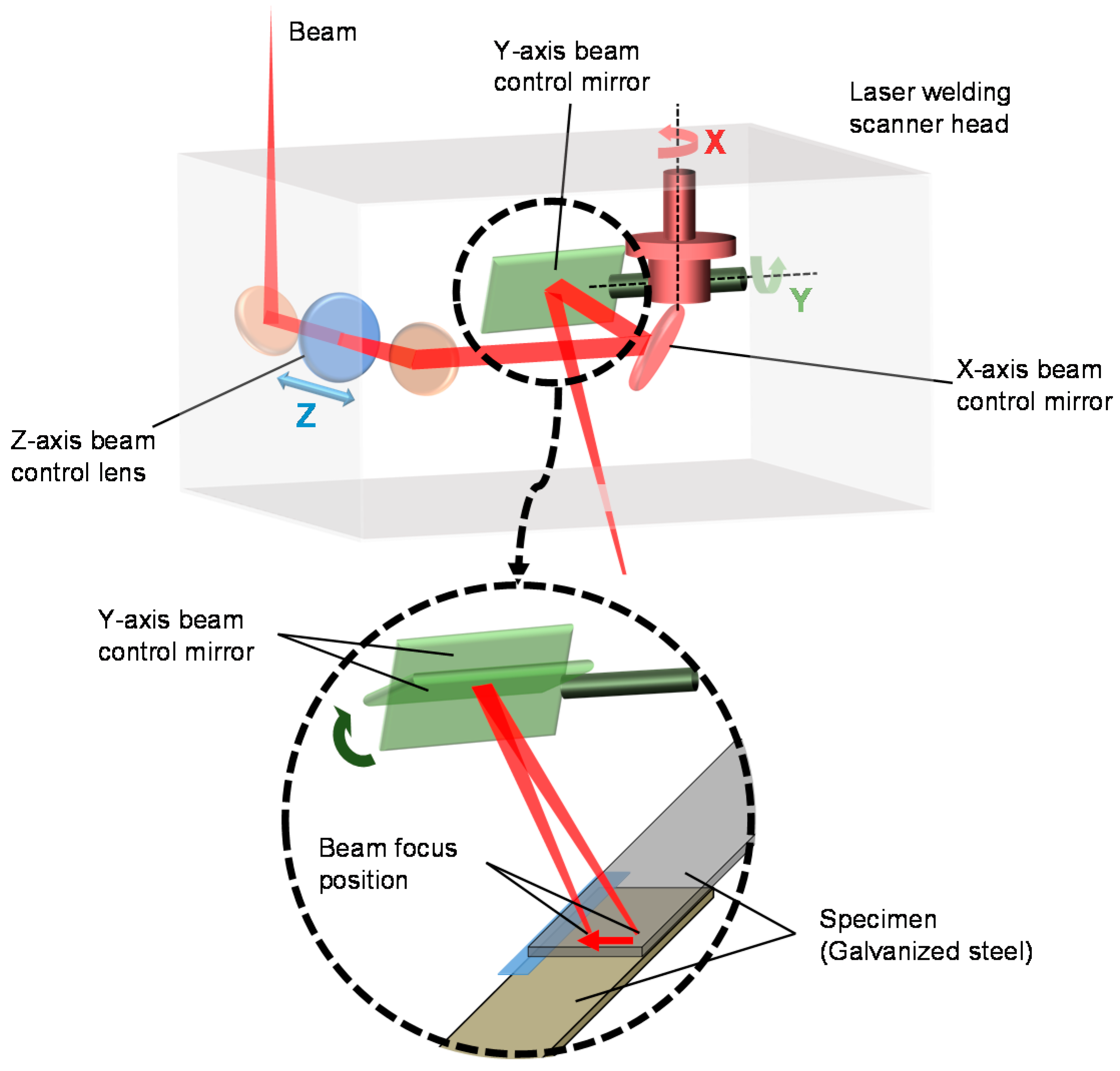
Metals 06 00184 g001
Figure 2. A schematic illustration of a laser welding scanner head that can easily change the direction of welding.
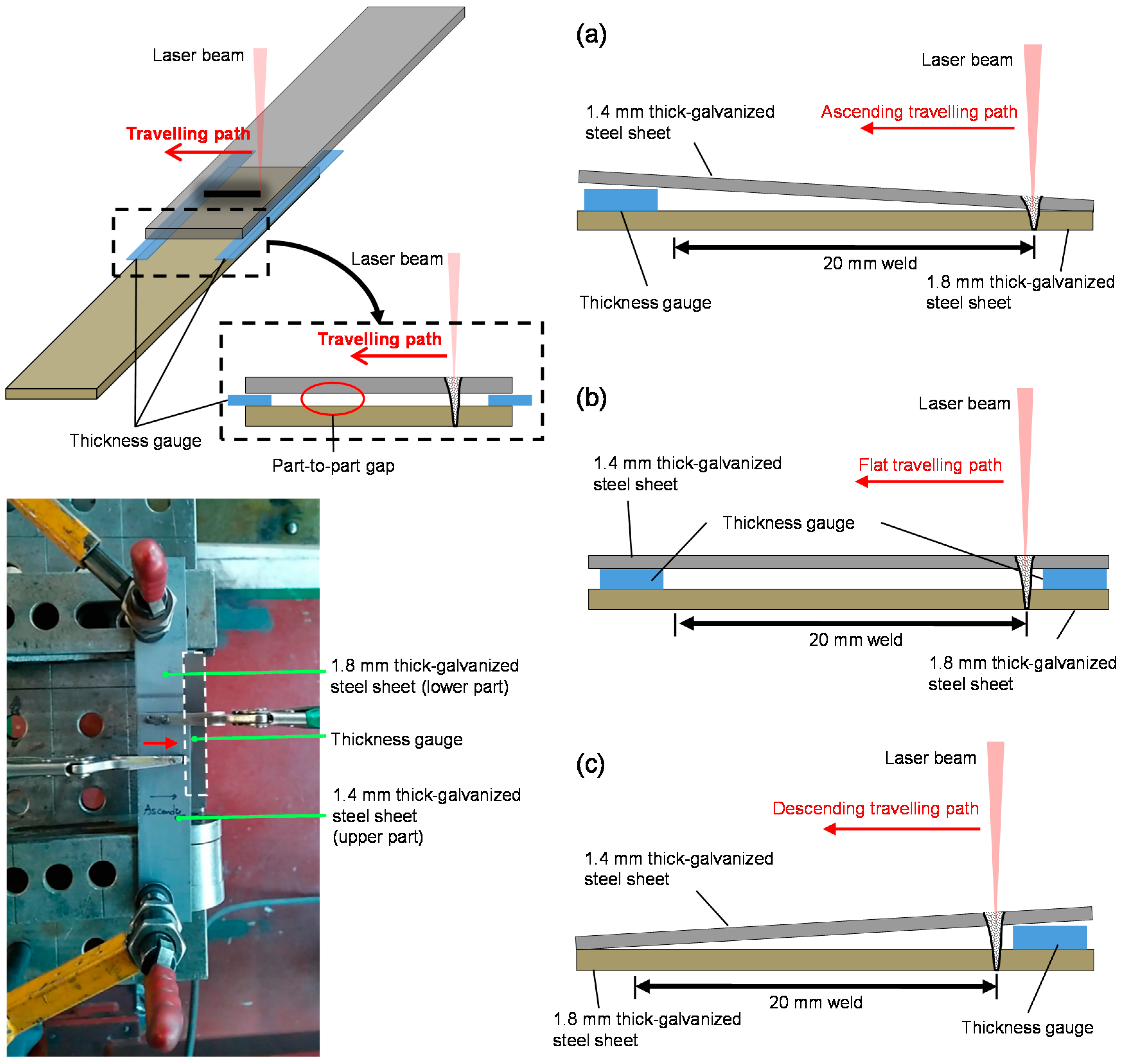
Metals 06 00184 g002
Figure 3. Weld joint configuration clamped at the two corners and the three types of travelling paths: (a) ascending; (b) flat; (c) descending.
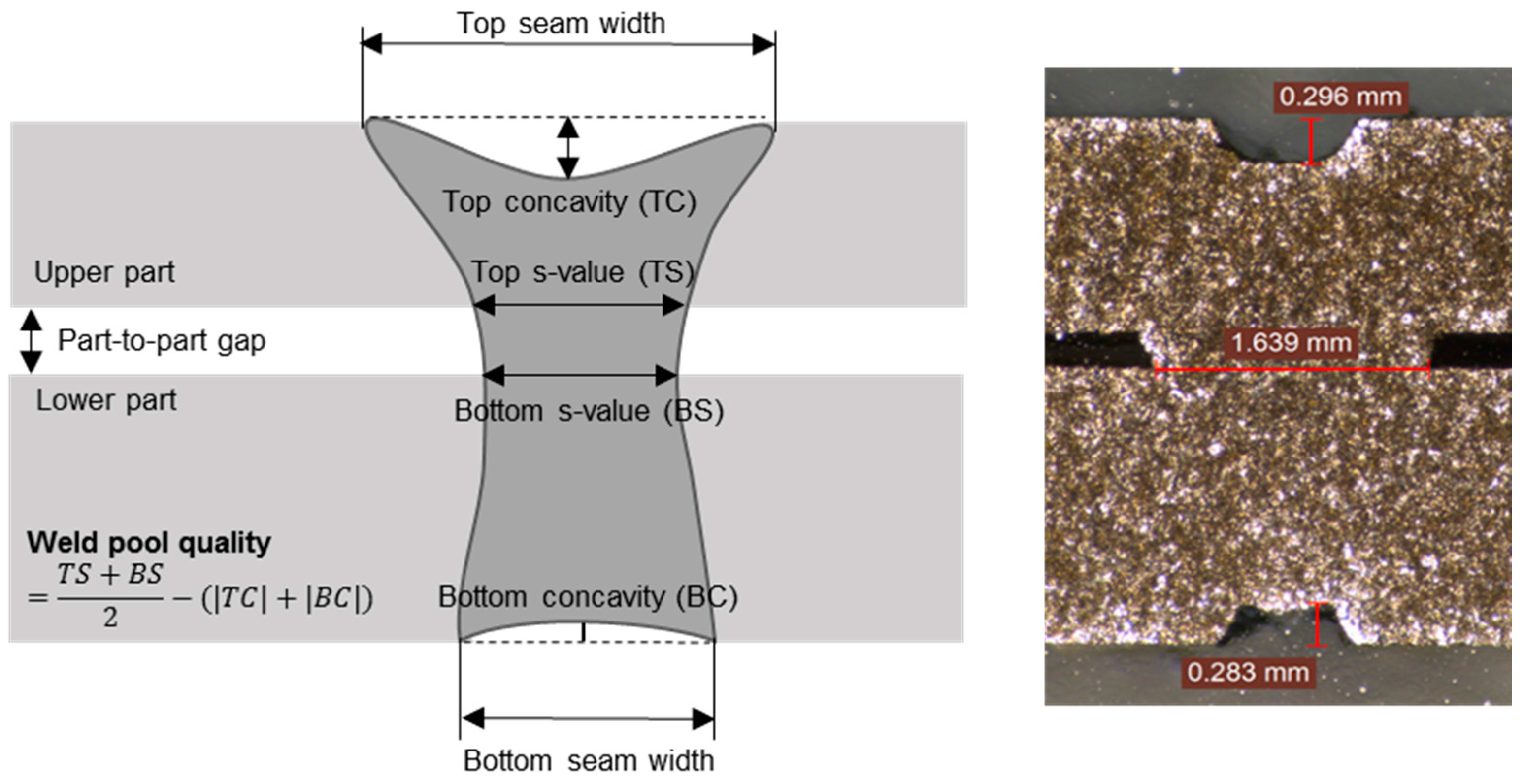
Metals 06 00184 g003
Figure 4. Definition of weld pool quality and an example of the cross sectional view at the middle of the specimen.
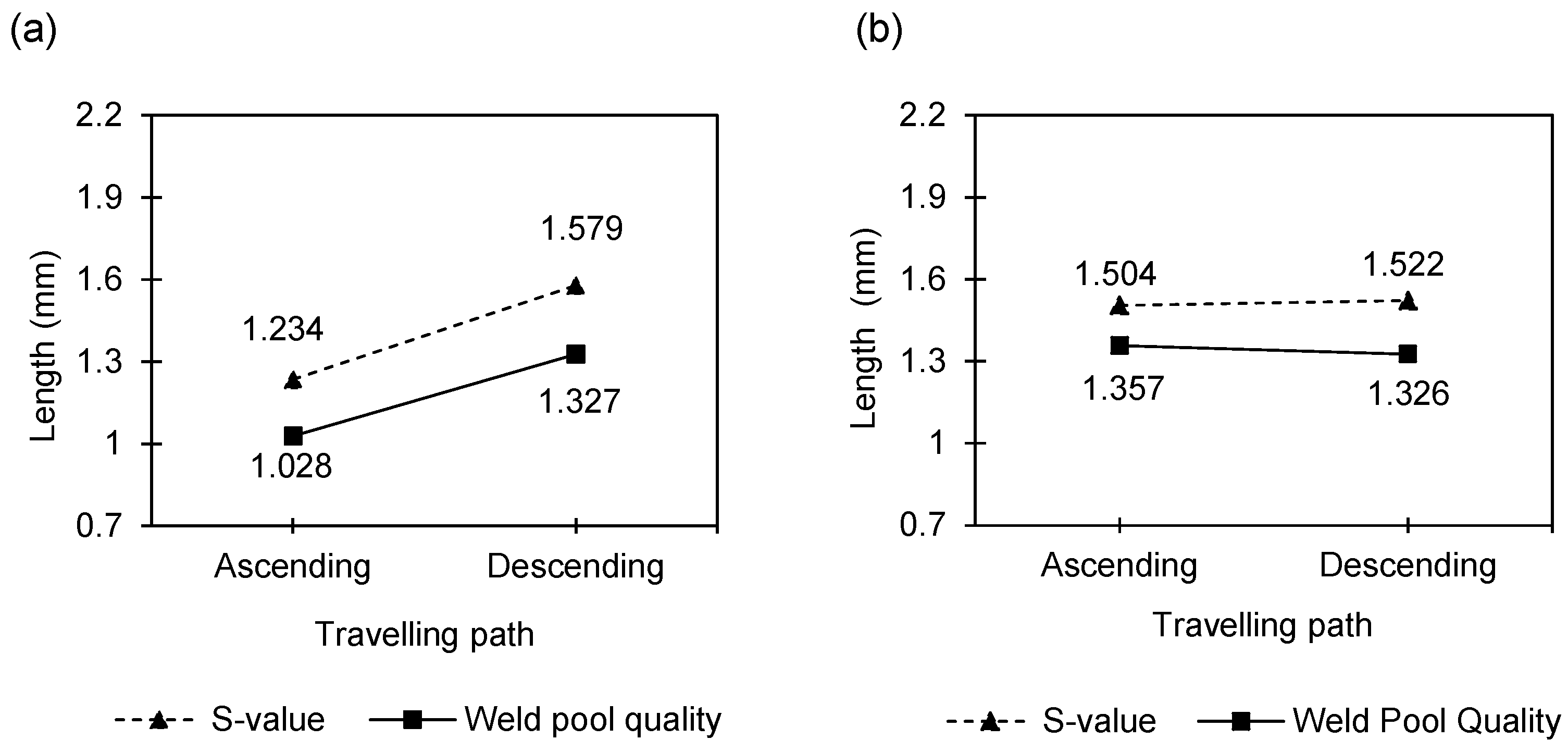
Metals 06 00184 g004
Figure 5. Main effect plots of the average s-value and weld pool quality in terms of the travelling path for experiment (a) #1-1 (laser power: 1.6, 1.8, and 2 kW, part-to-part gap: 0.3 mm) and (b) #1-2 (laser power: 4, 5, and 6 kW, part-to-part gap: 0.3 mm).
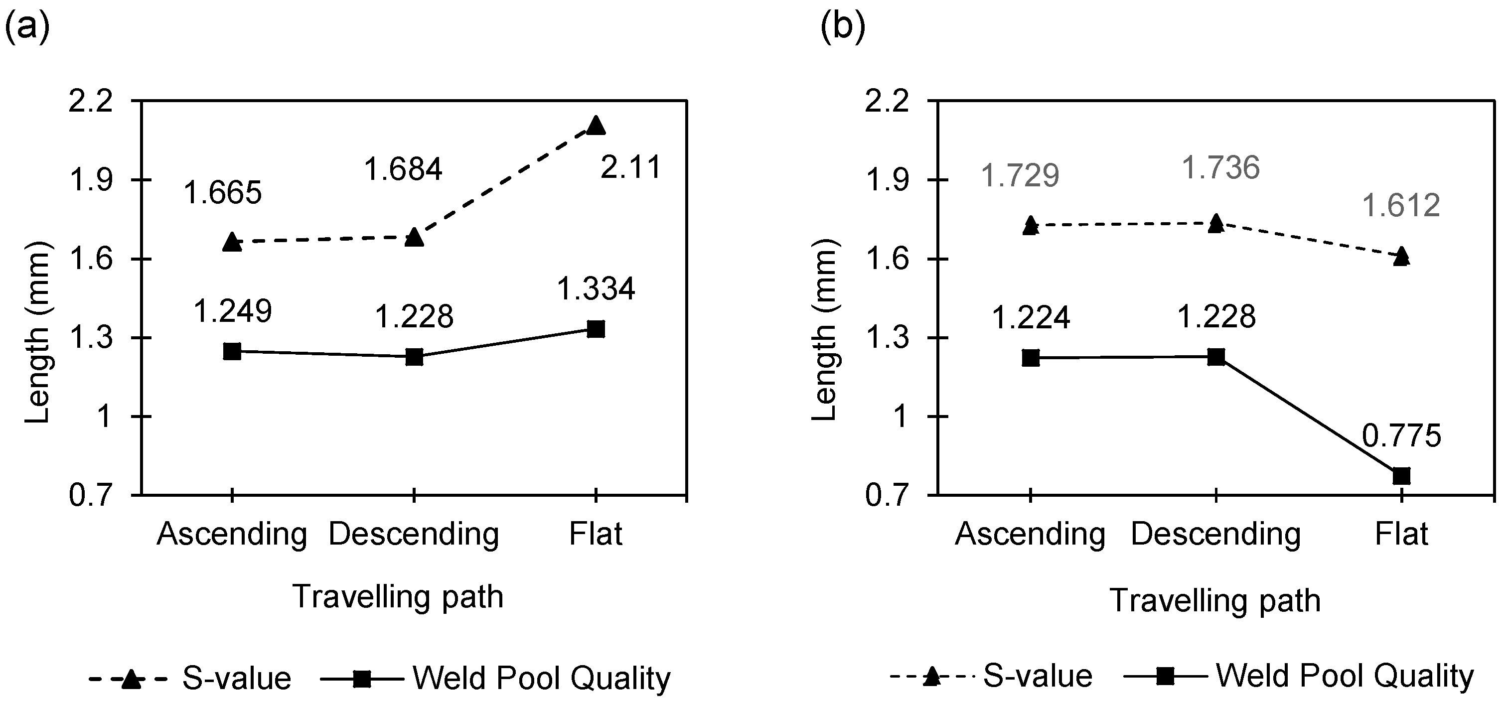
Metals 06 00184 g005
Figure 6. Main effect plots of the average s-value and weld pool quality in terms of the travelling path for experiment (a) #2-1 (laser power: 2 kW, part-to-part gap: 0.5 mm) and (b) #2-2 (laser power: 4, 5, and 6 kW, part-to-part gap: 0.5 mm).
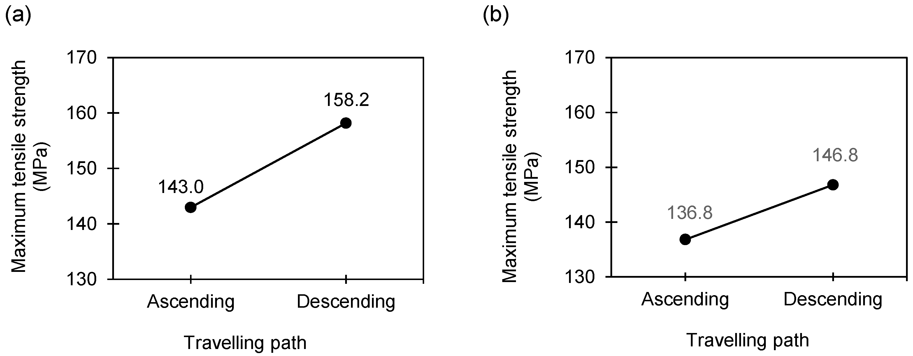
Metals 06 00184 g006
Figure 7. Main effect plots of maximum tensile strength in terms of the travelling paths for experiment (a) #3-1 (laser power: 2 kW, part-to-part gap: 0.3 mm) and (b) #3-2 (laser power: 4, 4.5, 5.5, and 6 kW, part-to-part gap: 0.3 mm).
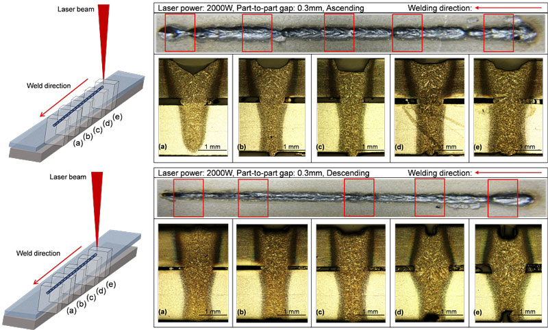
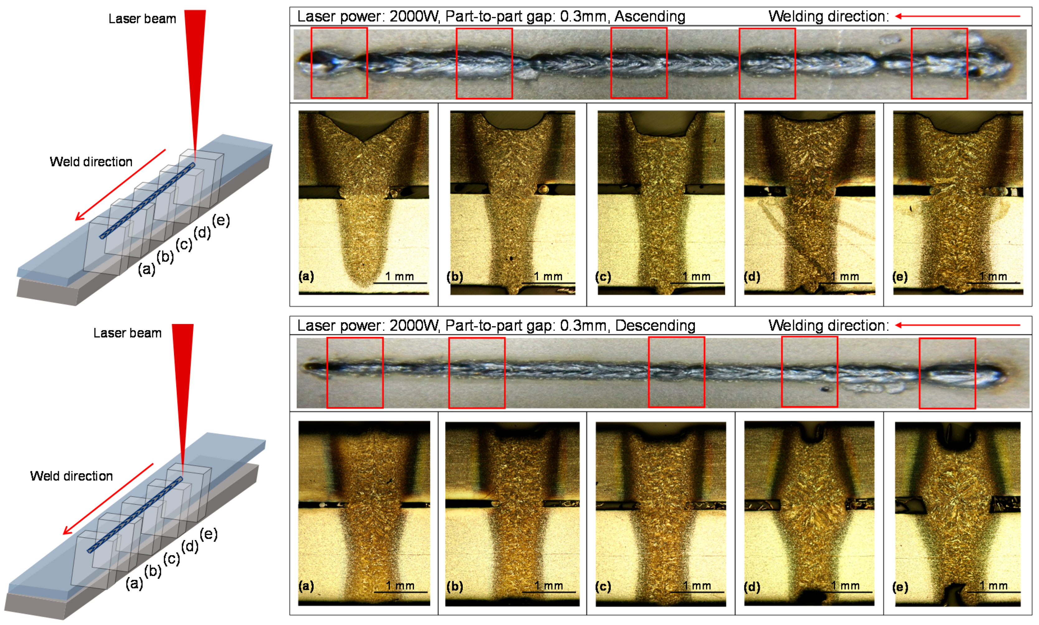
Metals 06 00184 g007
Figure 8. The lateral images of weld joints in the cases of ascending (top) and descending (bottom) travelling paths.
Metals 06 00184 g008
Table 1. The major process parameters in the laser lap welding of galvanized steel from literature.
Major Process ParametersLaser Welding QualityReferences
Laser power, focal position, welding speedHeat input and weld bead geometry (i.e., penetration depth, widths of welded zone, and heat-affected zone)Benyounis et al. [2], Wu et al. [3]
Part-to-part gapWeld depth, weld width, and concavityZhao et al. [9]
Laser power, welding speed, focal position, and shielding gasesStatic tensile strengthMei et al. [10]
Shielding gasesTensile strength and widths of heat-affected zoneChen et al. [11], Yang et al. [12]
Clamp pressureLap shear strength and weld seam widthAcherjee et al. [13], Anawa et al. [14]
Table 2. Technical parameters of the laser welding systems.
ParametersUnitFiber LaserDisk Laser
YLS-2000ACTruDisk6602
Max. laser powerkW2.06.6
Beam qualitymm × mrad6.08.0
Fiber diameterµm600200
Emission wavelengthnm10701030
Focal lengthmm278533
Table 3. Chemical composition (weight %) of the test materials.
Tested MaterialsDimension (mm) (length × width × thickness)Zinc Coating (g/m2)C (%)Si (%)Mn (%)P (%)S (%)
SGARC440 (Lower part)130 × 30 × 1.845.50.120.51.010.0210.004
SGAFC590DP (Upper part)130 × 30 × 1.445.40.090.261.790.030.003
Table 4. Mechanical properties of the test materials.
Tested MaterialTensile Test
Yield Strength (N/m2)Max-Tensile Strength (N/m2)Elongation (%)
SGARC440 (Lower part)327.5451.138
SGAFC590DP (Upper part)413.8625.728
Table 5. Experimental design.
ExperimentsExperimental FactorsPart-to-Part Gap (mm)Welding Speed (mm/min)
Laser Power (W)Type of Travelling Path
#1-11600Ascending0.3 (in-tolerance)800
3 levels × 2 levels with 2 replicates (2 kW fiber)1800Descending1000
2000 1250
#1-24000Ascending0.3 (in-tolerance)4000
3 levels × 2 levels with 5 replicates (6.6 kW disk)5000Descending5000
6000 6000
#2-12000Ascending0.5 (out-of-tolerance)900
3 levels with 10 replicates (2 kW fiber) Flat
Descending
#2-24000Ascending0.5 (out-of-tolerance)3000
3 levels × 3 levels with 4 replicates (6.6 kW disk)5000Flat4000
6000Descending4000
Table 6. The laser welding experimental data for experiment #1-1.
Laser PowerAverage s-Value/Weld Pool Quality (mm)
AscendingDescending
1.6 kW Metals 06 00184 i001
Average s-value/Weld pool quality (mm)
Metals 06 00184 i002
1.8 kW Metals 06 00184 i003 Metals 06 00184 i004
2 kW Metals 06 00184 i005 Metals 06 00184 i006
Table 7. The laser welding experimental data for experiment #1-2.
Laser PowerAverage s-Value/Weld Pool Quality (mm)
AscendingDescending
4 kW Metals 06 00184 i007 Metals 06 00184 i008
5 kW Metals 06 00184 i009 Metals 06 00184 i011
Metals 06 00184 i010 Metals 06 00184 i012
6 kW Metals 06 00184 i013 Metals 06 00184 i014
Table 8. ANOVA table for experiment #1-1 (2-kW fiber laser welding system).
SourceDegree of FreedomSum of SquaresMean SquareF-RatioP-Value
Blocks10.001650.001650.050.828
Laser power20.012560.006280.20.824
Travelling path10.268950.268958.60.033
Laser power × Travelling path20.012810.006410.20.821
Error50.156280.03126
Total110.45224
Table 9. ANOVA table for experiment #1-2 (6.6-kW disk laser welding system).
SourceDegree of FreedomSum of SquaresMean SquareF-RatioP-Value
Block40.04790.01201.340.291
Laser power20.06660.03333.710.043
Travelling path10.00720.00720.810.380
Laser Power × Travelling path20.03730.01872.080.151
Error200.17930.0090
Total290.3383
Table 10. The laser welding experimental data of experiment #2-1.
Laser PowerAverage s-Value/Weld Pool Quality (mm)
FlatAscendingDescending
2 kW Metals 06 00184 i015 Metals 06 00184 i016 Metals 06 00184 i017
Table 11. The laser welding experimental data of experiment #2-2.
Laser PowerAverage s-Value/Weld Pool Quality (mm)
FlatAscendingDescending
4 kW Metals 06 00184 i018 Metals 06 00184 i019 Metals 06 00184 i020
5 kW Metals 06 00184 i021 Metals 06 00184 i023 Metals 06 00184 i025
Metals 06 00184 i022 Metals 06 00184 i024 Metals 06 00184 i026
6 kW Metals 06 00184 i027 Metals 06 00184 i028 Metals 06 00184 i029
Table 12. ANOVA table of the s-value for experiment #2-1 (2-kW fiber laser welding system).
SourceDegree of FreedomSum of SquaresMean SquareF-Ratiop-Value
Travelling path20.06300.03151.060.361
Error270.80260.0297
Total290.8656
Table 13. ANOVA table for experiment #2-2 (6-kW disk laser welding system).
SourceDegree of FreedomSum of SquaresMean SquareF-Ratiop-Value
Blocks30.04370.01461.620.212
Laser power20.05070.02542.810.08
Travelling path21.61030.805189.330.00
Laser power × Travelling path40.46160.115412.80.00
Error240.21630.0090
Total352.3826
Table 14. The laser welding experimental data of experiment #3-1 (laser power: 2 kW, part-to-part gap: 0.3 mm) and experiment #3-2 (laser power: 4, 4.5, 5.5, and 6 kW, part-to-part gap: 0.3 mm)
Experiment #3-1Experiment #3-2
Laser PowerMaximum Tensile Strength (MPa)Laser PowerMaximum Tensile Strength (MPa)
AscendingDescendingAscendingDescending
2 kW143.150138.0444 kW130.195154.848
157.330161.804132.497174.842
157.330142.091137.479141.421
167.639175.6564.5 kW143.150146.920
125.989151.240128.442139.133
177.610113.757126.111170.180
124.059155.1505.5 kW162.380133.611
139.451166.041138.745142.645
156.543167.844122.292157.112
6 kW152.604145.174
163.173145.174
163.173122.911
Table 15. ANOVA table of the tensile strength for experiment #3-1 (2-kW fiber laser welding system).
SourceDegree of FreedomSum of SquaresMean SquareF-Ratiop-Value
Travelling path1103710375.440.033
Error163053191
Total174090
Table 16. ANOVA table of the tensile strength for experiment #3-2 (6.6-kW disk laser welding system).
SourceDegree of FreedomSum of SquareMean SquareF-Ratiop-Value
Laser power3419139.70.620.612
Travelling path1552.9552.92.450.137
Laser power × Travelling path31200.7400.21.780.192
Error163603.5225.2
Total235776.1
Table 17. Summary of the four experiments.
ExperimentsPart-to-Part Gap (mm)Significance of Welding Direction
#1-1 (2-kW fiber) 3 levels × 2 levels with 2 replicates0.3 (in-tolerance)Descending ≥ Ascending
#1-2 (6.6-kW disk) 3 levels × 2 levels with 5 replicates0.3 (in-tolerance)X
#2-1 (2-kW fiber) 3 levels with 10 replicates0.5 (out-of-tolerance)X
#2-2 (6.6-kW disk) 3 levels × 3 levels with 4 replicates0.5 (out-of-tolerance)X

