Article

Synergistic Effect of Alloying on the Strength and Ductility of High Carbon Pearlitic Steel

1
School of Materials Science and Engineering, Shanghai University, Shanghai 200444, China
2
Laboratory for Microstructures, Shanghai University, Shanghai 200444, China
3
Shanghai Key Laboratory of Materials Laser Processing and Modification, Shanghai Jiao Tong University, Shanghai 200240, China
4
School of Materials Science and Engineering, Shanghai Jiao Tong University, Shanghai 200240, China
5
R&D Center, Long Products Research Institute, Baoshan Iron & Steel Co., Ltd., Shanghai 201900, China
*
Author to whom correspondence should be addressed.
Metals 2023, 13(9), 1535; https://doi.org/10.3390/met13091535
Submission received: 31 July 2023 / Revised: 15 August 2023 / Accepted: 28 August 2023 / Published: 30 August 2023
(This article belongs to the Special Issue Phase Transformation and Microstructure Characterization in Steels)

Abstract

:
In this work, the effects of the micro-alloying of Mn, Ni, and Si on the microstructure and mechanical properties of high-carbon pearlite steels were investigated. The results indicated that the addition of solely Ni to high-carbon pearlitic steel can enhance the strength through the refinement of interlamellar spacing, but work-hardening in the ferrite of the pearlite colony may be delayed, leading to a reduction in area. The multiple additions of Ni and the increase in Mn and Si contents in high-carbon pearlitic steel were beneficial to obtaining a balance between ultimate tensile strength and reduction in area. Three-dimensional atom probe tomography results showed Si partitioning into ferrite and Mn and Ni elements partitioning into cementite. The addition of Si inhibited the formation of a continuous network of grain-boundary cementite, leading to high strength and high ductility through optimization of the microstructure.

1. Introduction

High-carbon pearlitic steel wires with a tensile strength in the range of 2~4 GPa are extensively used in a variety of applications, e.g., suspension cables, tire cords, and piano strings [1,2,3,4]. Even higher tensile strengths of close to 7 GPa, which is close to the strength limit of the steel materials, could be achieved after heavy cold-drawn processing [5]. To increase the strength of the cable with limited reductions in cross-section, it is important to increase the tensile strength of the rod prior to cold-drawing. The most efficient way to achieve high strength in steel is to add alloying elements, especially carbon, to refine the original pearlite structure and improve the ductility of the steel [6,7,8,9,10,11,12,13,14,15,16]. Many studies focused on the investigation of the effect of strong carbide formers, e.g., niobium and vanadium, which were proven to change the stoichiometric composition of pearlitic cementite and form additional carbide dispersions in the microstructure. Some researches indicate that the grain refinement effect of Nb is greater than that of coarsening interlamellar spacing during hot rolling deformation [17]. The effects of strong carbide formers on the mechanical properties of pearlitic steels can summarized as follows [17,18,19,20,21]: increase the strength by decreasing the lamellar spacing and the smaller nodule size and more uniform grain size distribution; decrease the reduction in area by increments in austenite grain size and carbide plate thickness.
It is well known that alloying elements can affect the activation energy required for the diffusion of carbon, thus altering pearlite transformation rates [10]. The addition of alloying elements dominates the interlamellar spacing of the pearlite in the microstructure and the element distribution during the phase change, which is not the result of adding only one element and sometimes involves a combination of multiple elements. Vanadium-microalloyed eutectoid steels show a delay in pearlite transformation with the addition of niobium and accelerate pearlite transformation with increased nitrogen [8]. Si strengthens the pearlite structure mainly through the solid solution strengthening of the ferrite phase. V mainly enhances the strength of pearlite by precipitating the strengthening of pearlitic ferrite [11,12]. The addition of silicon and vanadium to very-high-carbon steel (>0.8 wt.% C) also inhibits the formation of a continuous grain boundary cementite network, thus ensuring the hypereutectoid steel’s high strength and ductility for cold-drawing.
However, the effect of the non-carbide-forming element on the properties of pearlitic steels is different from that of the strong carbide-forming element. The most effective alloy elements for the composition ranges studied in fully pearlitic steels are Si and Ni for improvements in strength and Ni and Mn for toughness [10]. In an investigation on the effect of the addition of nickel to low-alloy steels, the addition of nickel proved to improve impact toughness and fracture toughness through a refinement of effective grain size [15]. Mn, an austenite-stabilizing element, delays the pearlitic transformation, improves the stability of the cementite phase, and can be used to refine interlamellar spacing [16]. Aranda et al., using TEM and APT measurements at the austenite/pearlite interface, indicated an increase in the Mn content in the ferrite and cementite phases during grain growth [16]. The rate at which Si diffuses from the cementite phase limits the growth kinetics of the pearlite [22]. Very few studies have reported that the composite addition of a non-carbide-forming element in high-carbon pearlitic steels refines pearlite interlamellar spacing and increases mechanical properties. Therefore, it is important to investigate the composite effect of the non-carbide-forming element’s addition to pearlitic transformation and properties in high-carbon pearlitic steels.
In the present study, four kinds of high-carbon pearlitic steels were designed with increased content of Mn, Ni, and Si. The present work was undertaken to explore the effects of non-carbide-forming elements Mn, Ni, and Si on the microstructure and mechanical properties of fully pearlitic steel and to identify the strengthening and toughening mechanisms of alloyed high-carbon pearlitic steels.

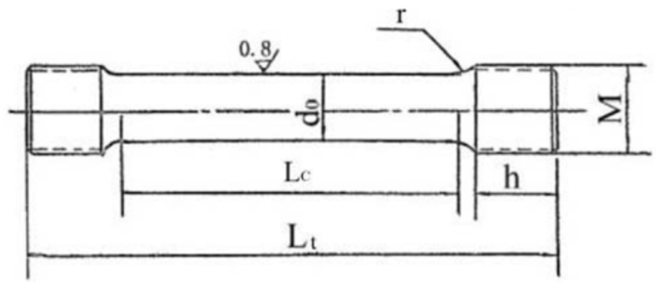
2. Materials and Methods

Four different materials were used in this study, with compositions shown in Table 1. High-carbon steel D1 was provided by an industrially hot-rolled wire rod. Another three alloyed materials were designed based on industrially hot-rolled wire rods. The rods had a 13 mm diameter that was subsequently machined into tensile specimens with the geometry shown in Figure 1. The mechanical properties of the test specimen’s actual processing size were d0 = 6 ± 0.1 mm, M = 12 mm (thread), h = 15 mm, r = 15 mm, Lc = 70 mm, and Lt = 118 mm. The mechanical characteristics were determined by tensile tests at room temperature using a Zwick-Z100/SN3A testing machine. Austenitizing treatment was applied to all samples at 960 °C for 5 min. Then, the austenitizing samples were immediately placed in the isothermal salt bath furnace at 537 °C or 545 °C for 600 s. Twelve samples were measured, and each given steel variant was performed three times to obtain accurate data. The tensile test was performed based on the ASTM standard.
A SUPRA-40 field emission scanning electron microscope (FESEM) was used for microstructural characterization, including qualitative identification of constituent phases and measurement of pearlite colonies.
Thin foils for TEM observation were prepared by electropolishing at −20 °C in a Struers (Tenupol-5, Denmark) machine. The electrolyte consisted of a 5% perchloric acid-alcohol solution. The lamellar spacing and morphology of pearlite were observed by transmission electron microscopy (TEM, JEOL JEM-2100F, Japan).
For elemental analysis of 3DAP, three samples were selected for each steel, which were cut into 0.5 × 0.5 × 15 m m 3 thin rods and electropolished with perchloric acid to form a tip shape. Atom probe tomography was conducted at CSM using a Cameca LEAP 4000 HR in laser pulse mode with a laser power of 10 pJ, a pulse frequency of 625 kHz, a detection rate of 2 pct, a specimen temperature of −218 °C, and an analysis chamber pressure of approximately 10−11 torr (1.33 × 10⁻⁹ Pa).

3. Results and Discussions

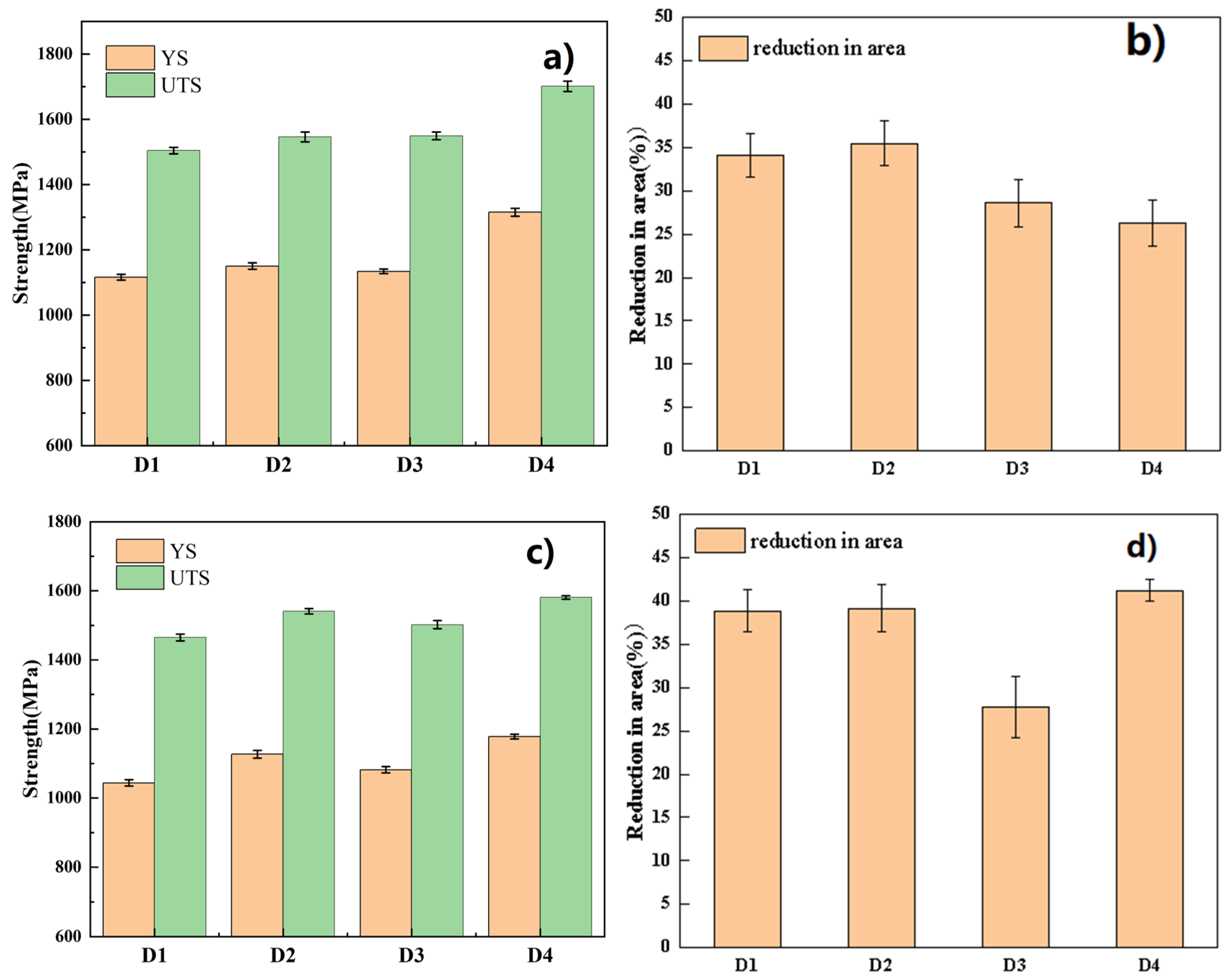
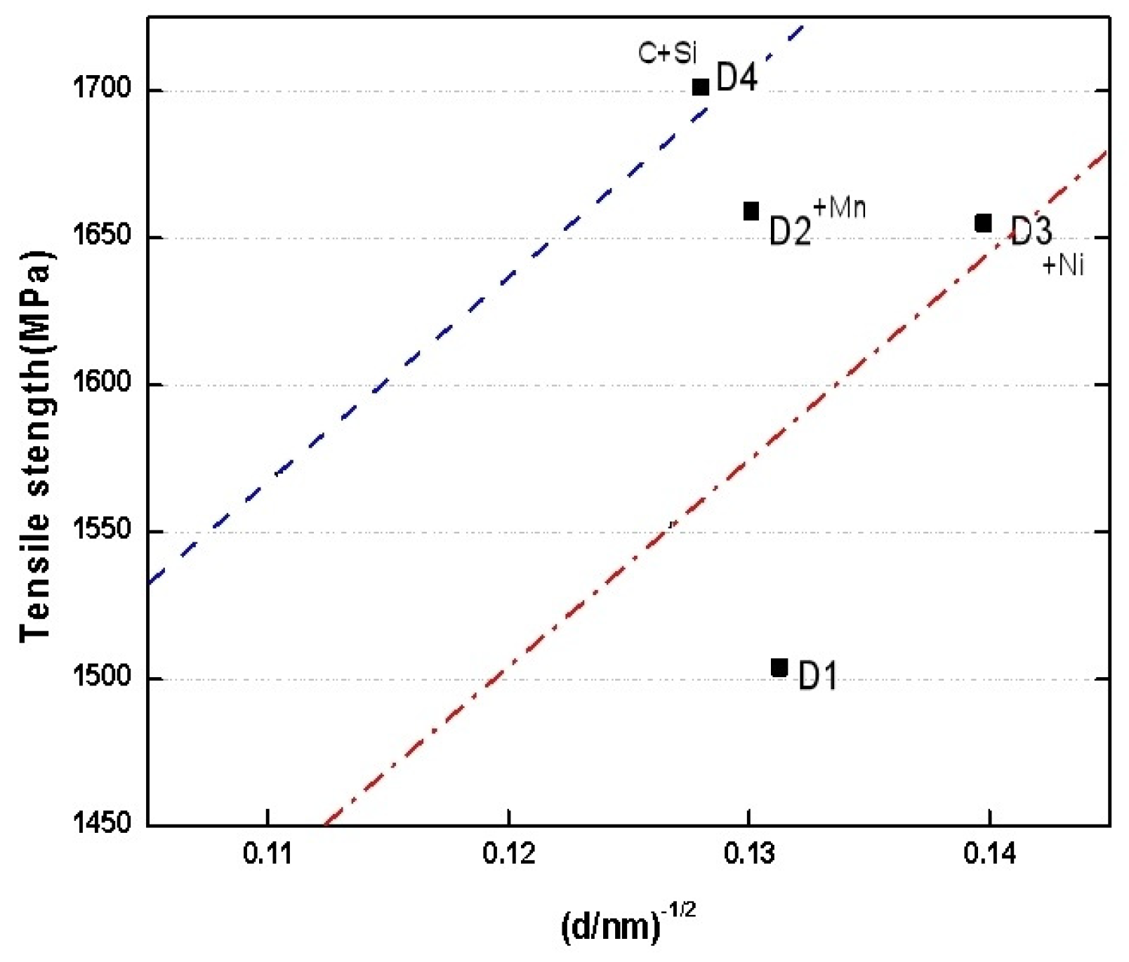
3.1. Mechanical Properties

Figure 2 depicts the strength (yield strength (YS); ultimate tensile strength (UTS)) and reduction in area (RA) of four samples after isothermal quenching in a 537 °C salt bath. D1, D2 (+Mn), D3 (+Ni), and D4 (+C+Si+Cr+Mn+Ni) steels exhibit a high tensile strength, close to 1.6 GPa, and show a good reduction in area (>25%). D2, D3, and D4 steel have a larger UTS than D1 steel. D4 steel has the highest UTS. From Figure 2b, it is interesting to note that compared with the other three steels, D2 steel has a larger RA, and D4 steel has the lowest RA. As mentioned before, it can be seen that the UTS of D4 steel containing Ni and the increased content of Mn and Si were significantly improved, but RA was decreased. However, when the isothermal treatment temperature was increased to 545 °C in D4 steel, the UTS decreased but the RA significantly increased. However, although the increase in isothermal salt bath temperature led to a decrease in the strength of D4 steel, the reduction in area increased significantly, reaching 41.22%. The RA and UTS balance of D4 steel that was isothermally treated at 545 °C is better than the other three kinds of steel at 537 °C. It is suggested that the addition of Ni and the increasing of Mn and Si contents have better performance benefits than the single addition of Ni and are beneficial to obtaining the balance of UTS and RA.

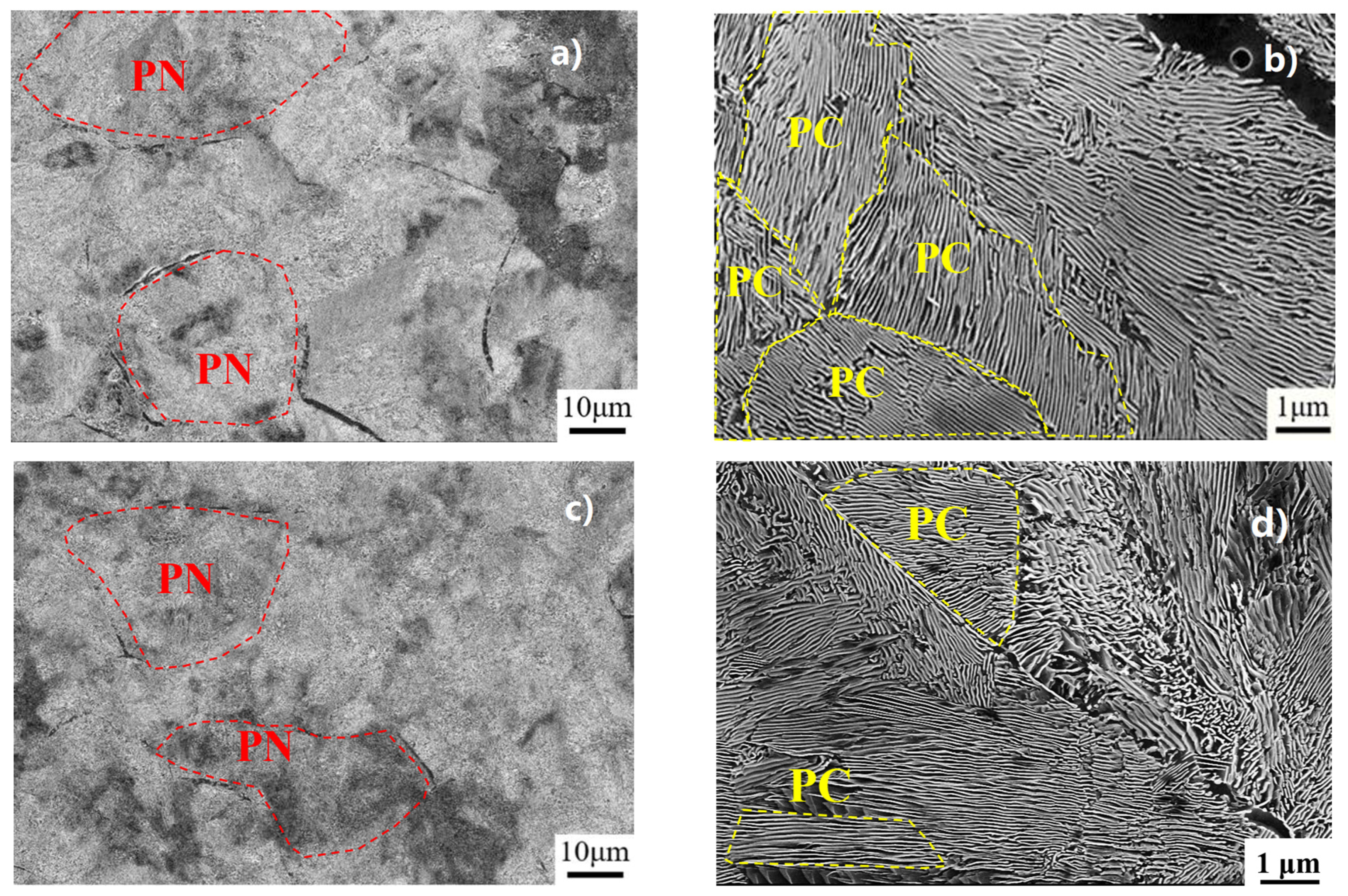
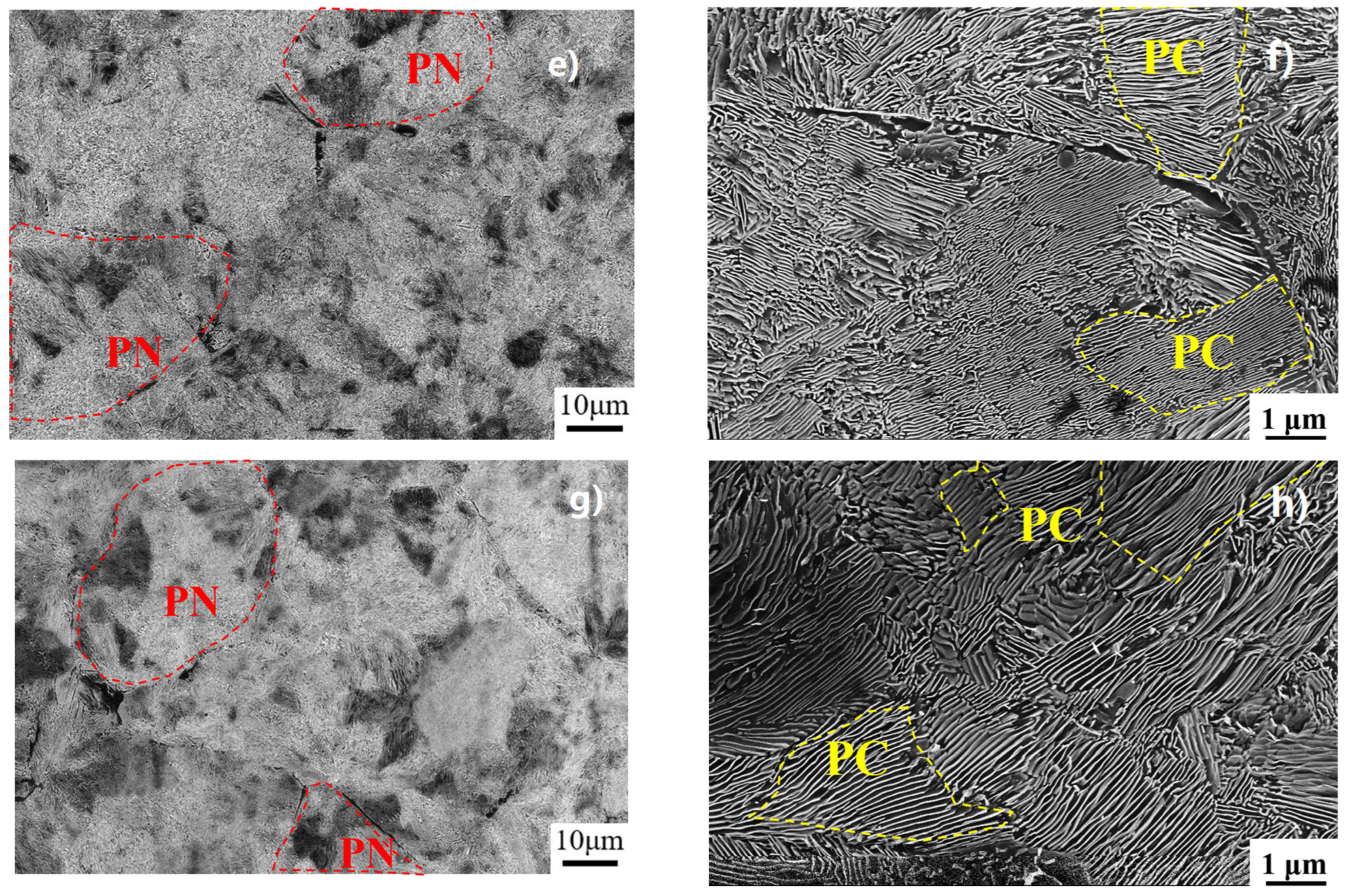
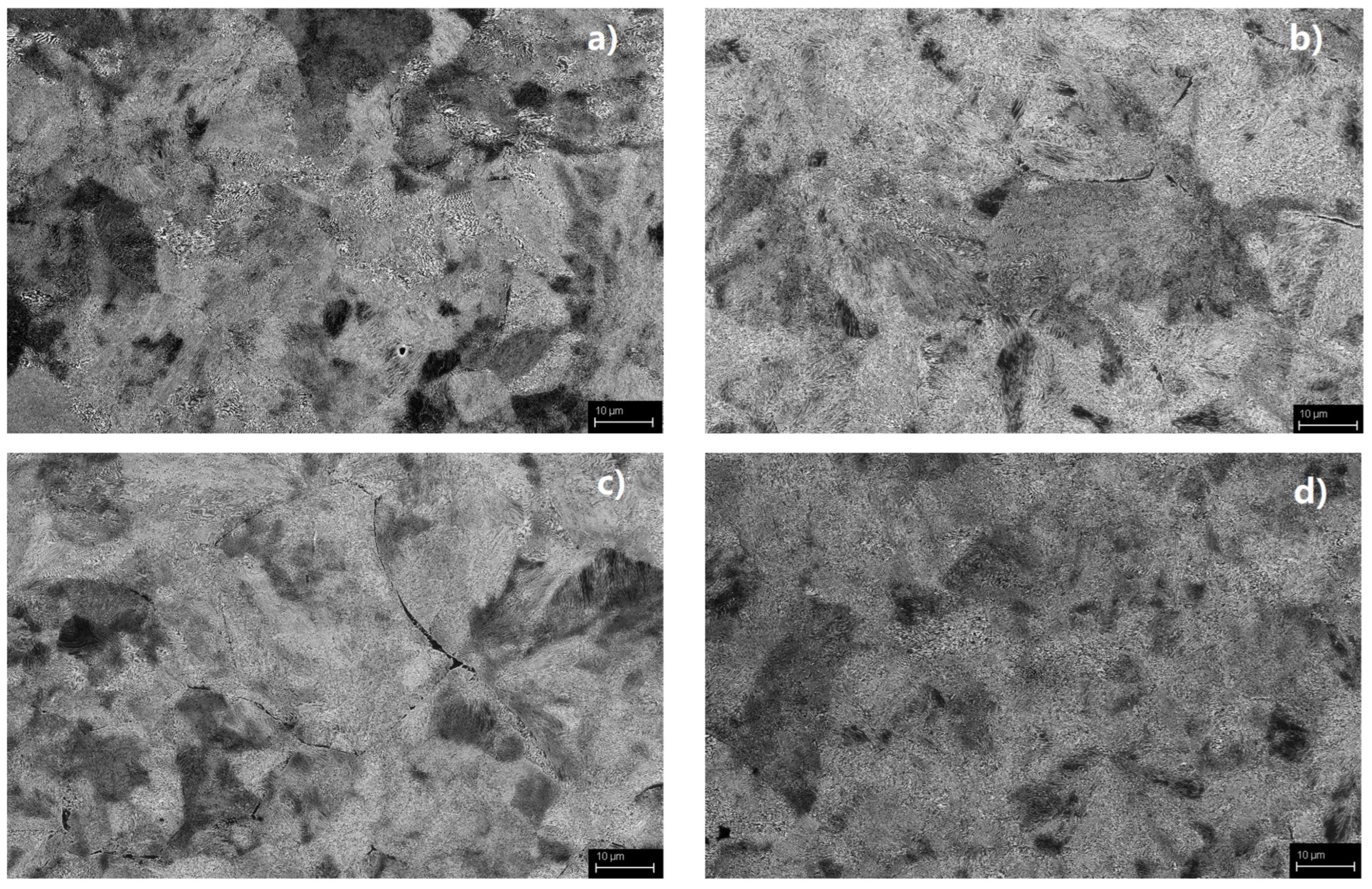
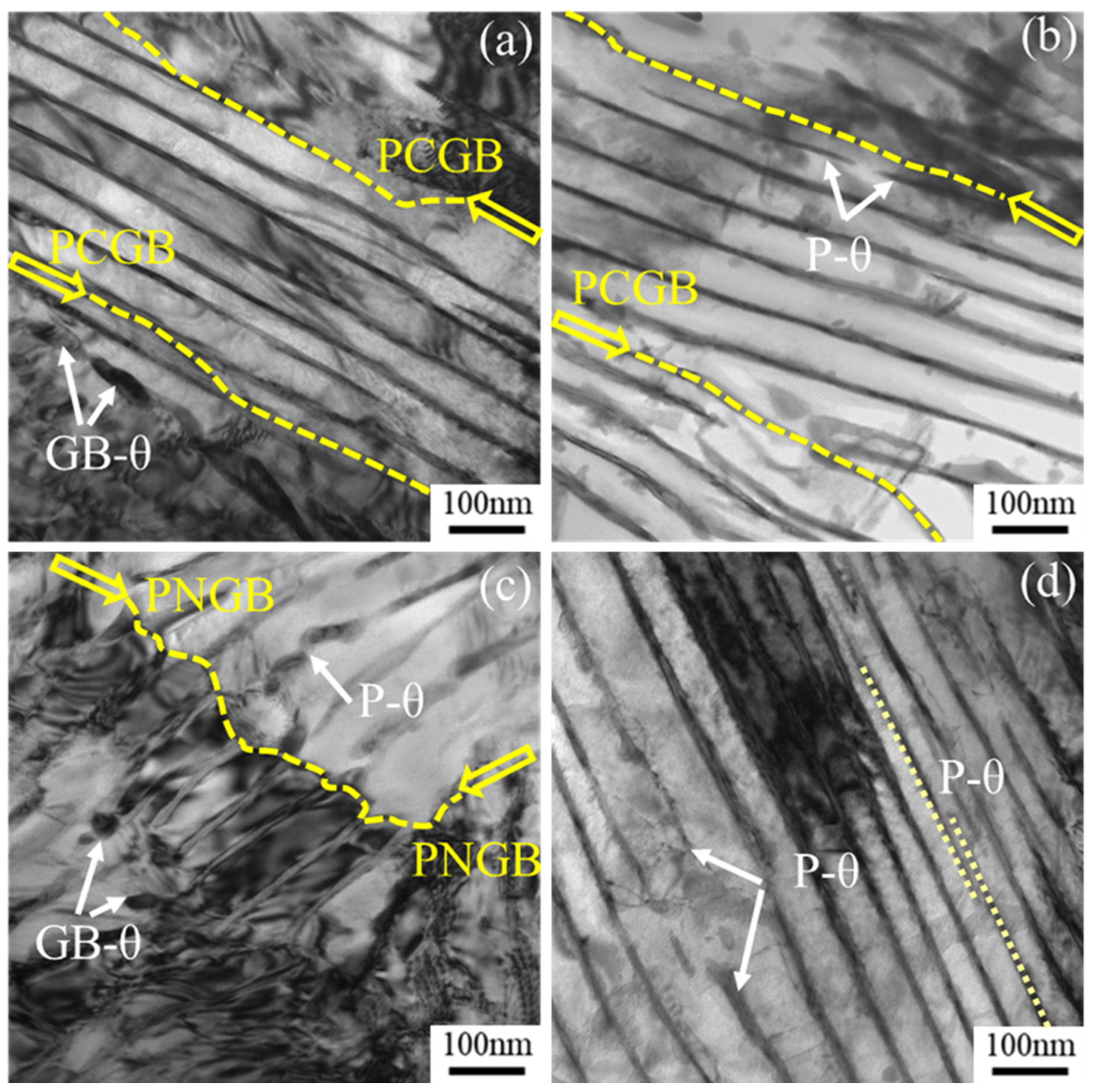
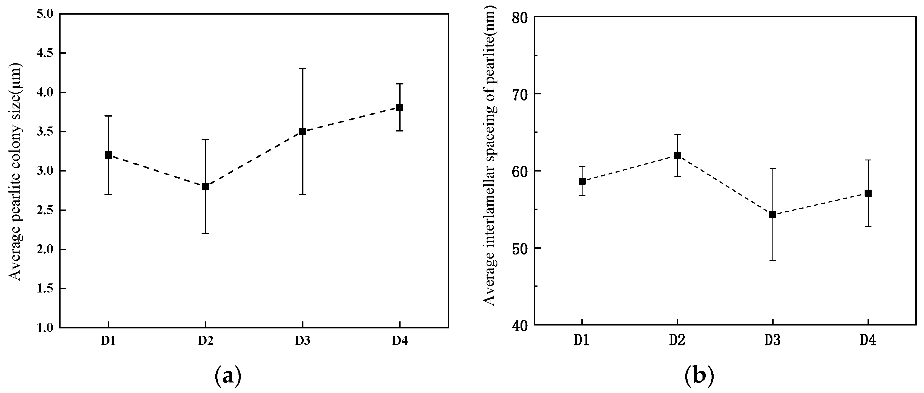
3.2. Microstructure Analysis

The pearlite is composed of several colonies of prior austenite grain. The colony consists of lamellae layers of ferrite and cementite. As shown in Figure 3, the lamellar pearlite colony is formed in a random manner during the isothermal transformation at 537 °C and 545 °C with different grain sizes. A colony is generally defined as a region with parallel-oriented pearlite lamellae. Figure 3b,d,f,h present representative FESEM images used for colony size determination with demarcated colony boundaries; the yellow dotted line represents pearlite colonies. Colony size measurements are presented in Figure 4a, with error bars representing one standard deviation from the mean. The average sizes of pearlite colonies were calculated from FESEM images to be 3.2 ± 0.5, 2.8 ± 0.6, 3.5 ± 0.8, and 3.81 ± 0.3 μm, respectively. The lamellar structure is shown in Figure 3a,c,e,g, in which ferrite is accompanied by the prior austenite (PAGB). There is a presence of grain boundary ferrite (GB-α) at the PAGB of each test steel. GB-α is evident in pearlite colonies or nodules. Different from pearlitic ferrite lamellae, it is an abnormal structure at the grain boundary and is closely related to the properties of the material [23]. In the four steels isothermal heat treatment at 545 °C, the amount fraction of GB-α obviously decreases. This phenomenon is also reported by other research [23,24]. Hillert [24] reported that the carbon content in austenite close to θ becomes lower than the Ae3 composition, leading to the nucleation of α. On the other hand, the volume fraction of GB-α increases with decreasing transformation temperature, carbon content, and prior austenite grain size [23]. However, through statistical observations based on SEM images of the same magnification in four steels, in D4 steels, less grain boundary ferrite could be observed, while it is noted that the pearlite colonies and the prior-austenite grain size of D4 steel were the lowest, at about 3 μm and 33 μm, respectively.
In order to accurately obtain the microstructure characterization of the pearlite of the steels, a TEM microscope is used to observe the substructure of the perlite, i.e., the interlamellar spacing (ILS), pearlite colony grain, and pearlite nodule grain, as shown in Figure 5. Figure 5a shows the microstructure of D1 steel. It is obvious that the pearlite colony grain boundary (PCGB) is decorated with grain boundary cementite (GB-θ), which has a rod-like morphology with a discontinuous structure due to the high interface energy. Figure 5b shows the pearlite microstructure of D2 steel, and the lamellar pearlite cementite (P-θ) at PCGB shows discontinuous growth. Compared with the former, Figure 5c shows that the grain boundary of D3 steel is a pearlite nodules grain boundary (PNGB), and the granular grain boundary cementite (GB-θ) and curve lamellar P-θ appear in the vicinity of this. Sometimes, discontinuous lamellar P-θ is also present inside the pearlite colony, as shown in Figure 5d, and the adjacent two interlamellar cementites in the same pearlite cluster are not all parallel; both angles sometimes differ by a certain angle. In the pearlite microstructure of D4 steel, shown in Figure 5d, no obvious grain boundary ferrite is observed. Other scholars have similar findings [25,26].
The interlamellar spacing determined using TEM foils with colonies oriented perpendicular to the incident electron beam is considered the most accurate, as lamellar orientation with respect to the incident beam can be crystallographically verified. Pearlite ILS measurements are provided in Figure 6. D3 steel with a single Ni addition exhibits a 7 nm refinement in ILS compared to D1 steel. Mn additions, the multiple addition of Ni, and the increasing of Mn and Si percent content did not provide statistically significant refinement of ILS based on the overlap of reported error margins for D1, D2, and D4 steels. A smaller size is more favorable for rotating the colony structure as a whole and leads to better deformation compatibility between colonies during testing. As a result, the ferrite/cementite lamellae in one colony tend to be aligned close to the tensile direction at a higher strain.
It is known that the true interlamellar spacing governs the yield stress of eutectoid steels [27], and the Hall-Petch relationships have been proposed to describe the dependence [28].
σ = σ 0 + k y d 1 / 2
where σ is the stress, σ0, is the friction stress, ky, is the Hall-Petch parameter, and d is the true interlamellar spacing of pearlite for high-carbon pearlitic steels.
Figure 7 shows the relationship between lamellar spacing and tensile strength based on the Hall-Petch type. It can be observed that, compared to based D1 steel, alloying additions enhance strength to different degrees, with Mn, Ni, and Si exhibiting superior effects. It is well known that the addition of carbide-forming elements such as V [12] and Nb increased the strength of pearlite mainly by precipitation strengthening of the pearlitic ferrite and improving the undercooling of the pearlitic transformation, resulting in finer lamellar spacing [29]. However, different from the influence of carbide-forming elements, the Mn, Ni, and Si elements may be attributed to their solid solution strengthening in ferrite and cementite as well as their interaction with solute atoms on dislocation.
The multiple additions of Ni and the increase in Mn and Si contents in high-carbon pearlitic steel resulted in a decrease in interlamellar spacing, which caused the strength to increase. However, work-hardening in ferrite may be lagged, which leads to the deterioration of reduction in area.
Figure 8 and Figure 9 present 3D-APT reconstructions for all elements. It can be shown that C, Cr, Mn, and Ni elements are observed at a higher density within cementite, and Si is enriched on the ferrite side of the ferrite/cementite interface. The concentration profiles shown in Figure 8 and Figure 9c present C, Cr, Mn, Ni, and Si concentrations as a function of distance at the ferrite and cementite interface, quantitatively expressing the enrichment of C, Cr, Mn, Ni, and Si elements in cementite. The amounts of all elements in cementite and ferrite were determined from APT data.
The average concentration of each element in cementite and ferrite is shown in Figure 10. The partitioning result of C is undeniable. The highest concentration of carbon in cementite is 24.06 ± 0.33 at.%, which is basically consistent with the Fe3C stoichiometry. However, the average concentration of carbon in the ferrite phase is only 0.04 at.%. The partitioning ratio K i is measured to quantitatively analyze the partitioning properties of elements in cementite and ferrite matrix, K i = C i C e m e n t i t e / C i F e r r i t e , where i = Si, Cr, Mn or Ni [15]. Table 2 lists the partitioning ratios of Si, Mn, Cr, and Ni between the two phases. One can see that Mn, Ni, and Cr present higher concentrations in cementite, but Si strongly partitions to the ferrite phase. Compared with D4 steel, the partitioning ratios of Si, Mn, Cr, and Ni are stronger in D3 steel, indicating greater partitioning of Mn, Cr, and Ni to the cementite phase. The partitioning ratio of Si, Mn, Cr, and Ni in higher alloying steel was greater than that in lower alloying high-carbon pearlitic steel, leading to greater partitioning of Mn, Cr, and Ni into the cementite phase. The Si element widely distributes into the ferrite lattice; its concentration reached its lowest point in the center of the cementite. On the contrary, the Cr, Mn, and Ni contents in the cementite are greater than those in the ferrite, indicating that the concentration of alloying elements is also constantly changing and redistributing during the growth of the phases. During pearlite phase transformation, the alloying elements prefer to partition into any of the cementite and ferrite phases.
According to the above analysis of the distribution of elements at the atomic scale of 3DAP, there is greater segregation of Mn, Cr, and Ni into the cementite phase, and the Si element is widely distributed into the ferrite lattice. The alloy atom can inhibit the broadening of the interlamellar spacing between ferrite and cementite phases during the diffusion and growth of pearlite structures.
Meanwhile, it is related to the alloy element’s chemical composition with regard to solution strengthening. According to the method [30], the solution strengthening due to the solutes of Si, Mn, Cr, and Ni can be calculated by Equation (2).
∑σ = 84Si + 32Mn − 30Cr + 33Ni
where the units of Si, Mn, Cr, and Ni are in wt.%. It is noted from the equation that the addition of Ni elements, the multiple addition of Ni, and the increasing Mn and Si percent content increase the strengthening effect of solid solutions significantly.
Miller and Smith [7] proposed the fracture of pearlite from the perspective of slip in the ferrite phase. The brittle cementite phase in pearlite is assumed to experience tensile deformation simultaneously with the ductile ferrite phase when the steel is subjected to tensile deformation. Tensile deformation activates dislocations in the ferrite phase, and then dislocations pile up at the ferrite/cementite interface. The brittle cementite lamellae against which the dislocations pile up eventually crack from stress concentration. Teshima considers that the plastic deformation behavior of pearlite is strongly affected by the alignment of the ferrite/cementite lamellae [31]. Nevertheless, work hardening caused by the dislocations piling up at the ferrite/cementite interface may be lagged, which leads to reductions in area.
Summarizing the above experiment results, it is obvious that the solid solution effect of the alloy element in ferrite dominates over these microstructural variations in terms of strength. Meanwhile, the strength is also related to the interlamellar spacing because the narrowing spacing increases pile-up stress. The reduction in area is related to the prior-austenite grain size and pearlite colony size. Because during the tensile process, work hardening in the ferrite of pearlite colonies may be lagged, leading to a reduction in area. Although the addition of Ni can refine the interlamellar spacing to increase the strength, it is beneficial to reduce the pearlite colony size and improve the ductility. Meanwhile, the higher alloying amount of Cr in the D4 specimen shows a relatively uneven partition of Ni, Cr, and Mn, probably due to the inter-diffusion, which may influence the local chemical composition and the mechanical properties. To obtain an optimum combination of high strength and ductility, the alloying additions and isothermal transformation temperatures need to be carefully controlled.

4. Conclusions

The effects of single Ni and the multiple addition of Ni, Si, and Mn on the microstructure and properties of high-carbon pearlitic steels were investigated, and the following conclusions could be drawn:
(1)
The addition of Ni alone to high-carbon pearlitic steel can enhance the strength, but it leads to reductions in area. The multiple addition of Ni and the increase in Mn and Si contents in high-carbon pearlitic steel resulted in a decrease in interlamellar spacing, which caused the strength to increase, and work hardening in the ferrite of pearlite colonies may be lagged, which leads to reductions in area.
(2)
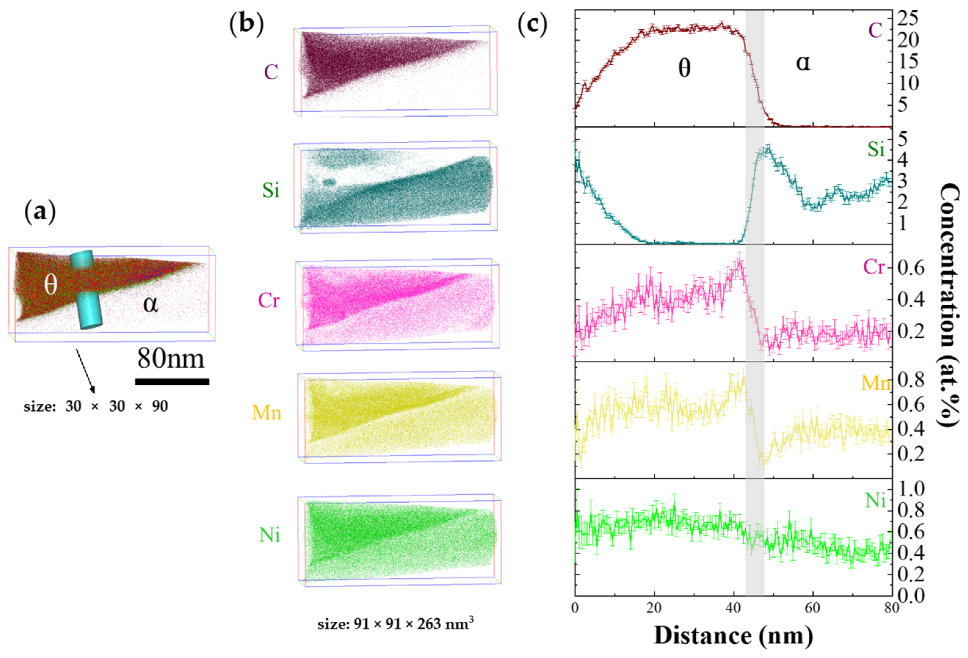
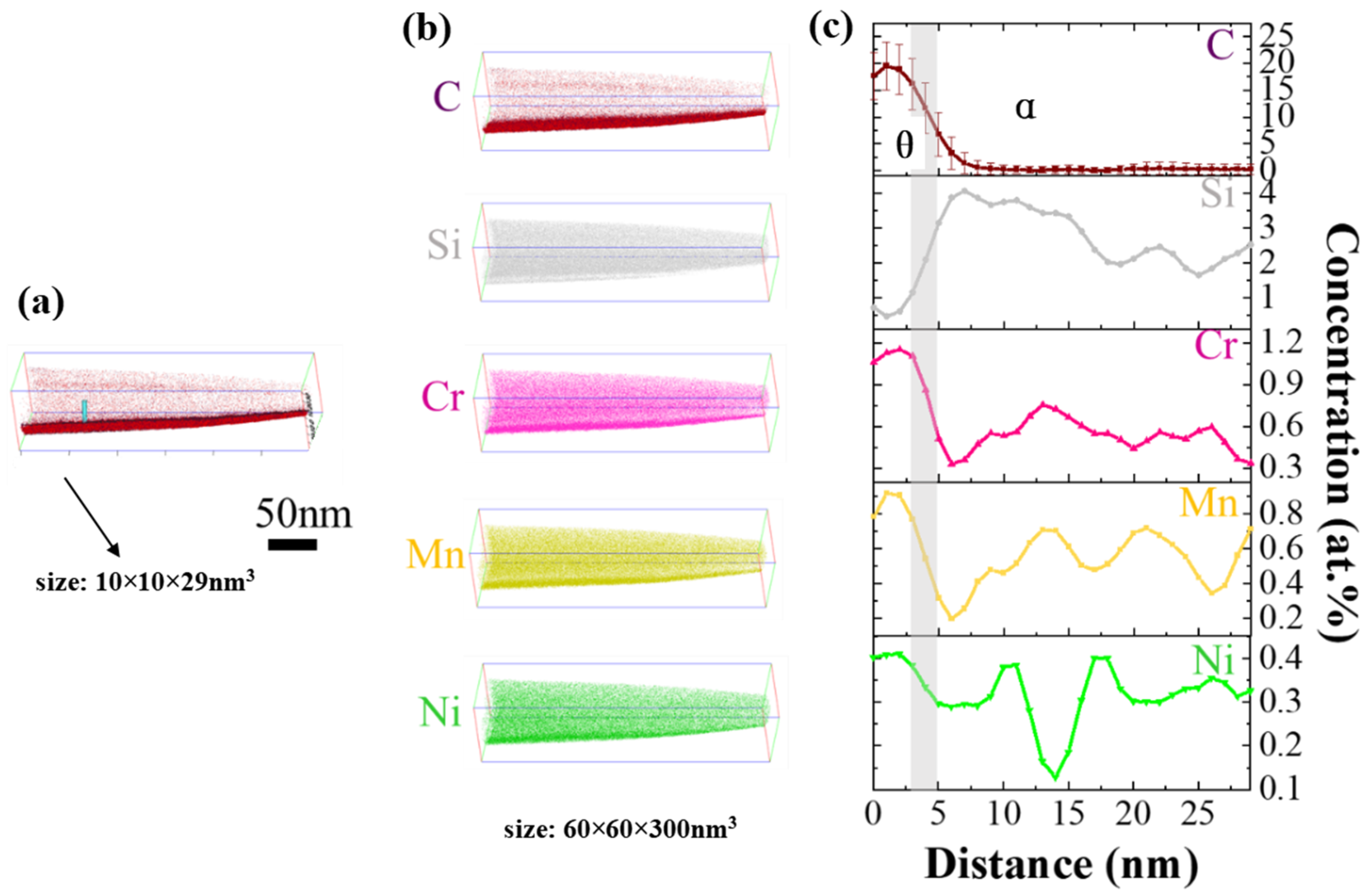
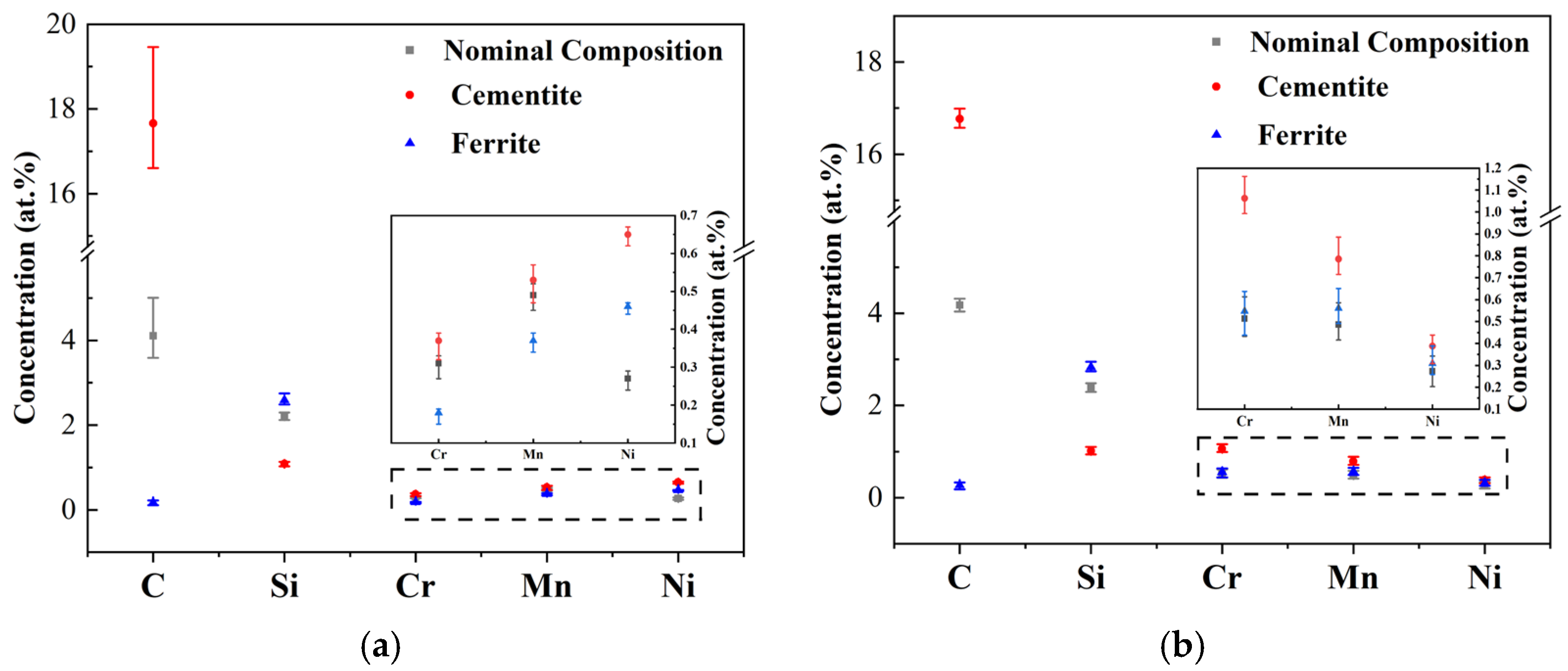
Three-dimensional atom probe tomography showed Si partitioning into ferrite and Mn, Cr, and Ni elements partitioning into cementite. The addition of Si inhibited the formation of a continuous network of grain-boundary cementite, leading to high strength and high ductility through optimization of the microstructure.

Author Contributions

Conceptualization, W.L. and N.M.; methodology, Y.X., L.Z., N.M.,Y.Z. and S.F.; software, Y.X., Y.Z. and S.F.; validation, W.L. and N.M.; investigation, N.M. and W.L.; resources, W.L., S.Z. and N.M.; data curation, Y.X., L.Z., Y.Z., S.F. and N.M.; writing—original draft preparation, N.M. and Y.X.; writing—review and editing, Y.X., L.Z., Y.Z., S.F., W.L., S.Z. and N.M.; visualization, N.M.; supervision, N.M.; project administration, W.L., S.Z. and N.M.; funding acquisition, W.L. and N.M., All authors have read and agreed to the published version of the manuscript.

Funding

This research was funded by the National Natural Science Foundation of China, grant number 52071209.

Data Availability Statement

The data presented in this study are available on request from the corresponding author.

Conflicts of Interest

The authors declare no conflict of interest.

References

  1. Ochial, I.; Nishida, S.; Ohba, H.; Kawana, A. Application of hypereutectoid steel for development of high strength steel wire. Tetsu-to-Hagane 1993, 26, 50. [Google Scholar]
  2. Fang, F.; Zhao, Y.; Zhou, L.; Hu, X.; Xie, Z.; Jiang, J. Texture inheritance of cold drawn pearlite steel wires after austenitization. Mater. Sci. Eng. A 2014, 618, 505–510. [Google Scholar] [CrossRef]
  3. Zelin, M. Microstructure evolution in pearlitic steels during wire drawing. Acta Mater. 2002, 50, 4431–4447. [Google Scholar] [CrossRef]
  4. Allain, S.; Bouaziz, O. Microstructure based modeling for the mechanical behavior of ferrite-pearlite steels suitable to capture isotropic and kinematic hardening. Mater. Sci. Eng. A 2008, 496, 329–336. [Google Scholar] [CrossRef]
  5. Li, Y.; Raabe, D.; Herbig, M. Segregation stabilizes nanocrystalline bulk steel with near theoretical strength. Phys. Rev. Lett. 2014, 113, 106104. [Google Scholar] [CrossRef] [PubMed]
  6. Han, K.; Smith, G.; Edmonds, D.V. Developments in ultra-high-carbon steels for wire rod production achieved through microalloying additions. Mater. Des. 1992, 14, 79–82. [Google Scholar] [CrossRef]
  7. Nakase, K.; Bernstein, I.M. The effect of alloying elements and microstructure on the strength and fracture resistance of pearlitic steel. Metall. Trans. A 1988, 19, 2819–2829. [Google Scholar] [CrossRef]
  8. Tian, J.Y.; Wang, H.X.; Zhu, M.; Zhou, M.X.; Zhang, Q.; Su, X.; Guo, A.M.; Xu, G. Improving mechanical properties in high-carbon pearlitic steels by replacing partial V with Nb. Mater. Sci. Eng. A 2022, 834, 142622. [Google Scholar] [CrossRef]
  9. Miller, S.L. Effect of Microalloying on Pearlite Transformation of High Carbon Wire Steels. Ph.D. Thesis, The Colorado School of Mines, Golden, CO, USA, 2015. [Google Scholar]
  10. Ridley, N. A review of the data on the interlamellar spacing of pearlite. Metall. Mater. Trans. A 1984, 15, 1019–1036. [Google Scholar] [CrossRef]
  11. Han, K.; Smith, G.; Edmonds, D. Pearlite phase transformation in Si and V steel. Metall. Mater. Trans. A 1995, 26, 1617–1631. [Google Scholar] [CrossRef]
  12. Han, K.; Edmonds, D.V.; Smith, G. Optimization of mechanical properties of high-carbon pearlitic steels with Si and V additions. Metall. Mater. Trans. A 2001, 32, 1313–1324. [Google Scholar] [CrossRef]
  13. Makii, K.; Yaguchi, H.; Kaiso, M.; Ibaraki, N.; Miyamoto, Y.; Oki, Y. Influence of Si on nano sub-structure of cementite lamellae in pearlitic steel wires. Scr. Mater. 1997, 37, 1753–1759. [Google Scholar] [CrossRef]
  14. Hyzak, J.; Bernstel, I. The role of microstructure on the strength and toughness of fully pearlitic steel. Metall. Trans. 1976, 7A, 1218–1224. [Google Scholar] [CrossRef]
  15. Huang, L.; Zhang, R.; Zhou, X.; Tu, Y.; Jiang, J. Atomic interactions between Si and Mn during eutectoid transformation in high-carbon pearlitic steel. J. Appl. Phys. 2019, 126, 245102. [Google Scholar] [CrossRef]
  16. Aranda, M.M.; Rementeria, R.; Poplawsky, J.; Urones-Garrote, E.; Capdevila, C. The role of C and Mn at the austenite/pearlite reaction front during non-steady-state pearlite growth in a Fe–C–Mn steel. Scr. Mater. 2015, 104, 67–70. [Google Scholar] [CrossRef]
  17. Zhu, X.X.; Zhou, J.; Hu, C.Y.; Wu, K.M.; Shen, Y.F.; Zhang, Y.Q.; Jiang, Y.D. Application Research on Nb Microalloying of High-Carbon Pearlite Bridge Cable Wire Rods. Materials 2023, 16, 2160. [Google Scholar] [CrossRef]
  18. Zhou, M.X.; Wang, H.X.; Zhu, M.; Tian, J.Y.; Su, X.; Zhang, Q.; Guo, A.M.; Xu, G. New insights to the metallurgical mechanism of niobium in high-carbon pearlitic steels. J. Mater. Res. Technol. 2023, 26, 1609–1623. [Google Scholar] [CrossRef]
  19. Su, X.; Zhou, M.X.; Zhu, M.; Wang, H.X.; Zhang, Q.; Tian, J.Y.; Xu, G. Microstructure and mechanical properties of Nb microalloyed high-carbon pearlitic steels subjected to isothermal transformation. Mater. Charact. 2023, 202, 113013. [Google Scholar] [CrossRef]
  20. Ma, Y.X.; Xu, P.W.; Liang, Y.; Xiang, S.; Yin, C.H. Improving the tensile ductility in the fully pearlitic steel using sequential refinement of colony and laminated structure. Mater. Sci. Eng. A. 2022, 851, 143642. [Google Scholar]
  21. Straffelini, G. Influence of Microstructure on Ductility, Ductility and Formability of Metals; Academic Press: Cambridge, MA, USA, 2023; pp. 185–217. [Google Scholar]
  22. Al-Salman, S.A.; Lorimer, G.W.; Ridley, N. Partitioning of silicon during pearlite growth in a eutectoid steel. Acta Metall. 1979, 27, 1391–1400. [Google Scholar] [CrossRef]
  23. Miyamoto, G.; Karube, Y.; Furuhara, T. Formation of grain boundary ferrite in eutectoid and hypereutectoid pearlitic steels. Acta Mater. 2016, 103, 370–381. [Google Scholar] [CrossRef]
  24. Hillert, M. The Formation of Pearlite; Interscience: New York, NY, USA, 1962; p. 197. [Google Scholar]
  25. Gershteyn, G.; Nurnberger, F.; Cianciosi, F. A Study of Structure Evolution in Pearlitic Steel Wire at Increasing Plastic Deformation. Steel Res. Int. 2011, 82, 1368–1374. [Google Scholar] [CrossRef]
  26. Zhao, T.Z.; Zhang, S.H. Influence of lamellar direction in pearlitic steel wire on mechanical properties and microstructure evolution. J. Iron Steel Res. Int. 2016, 23, 1290–1296. [Google Scholar] [CrossRef]
  27. Brandaleze, E. Structural evolution of pearlite in steels with different carbon content under drastic deformation during cold drawing. Procedia Mater. Sci. 2015, 8, 1023–1030. [Google Scholar] [CrossRef]
  28. Lewandowski, J.J.; Thompson, A.W. Microstructural effects on the cleavage fracture stress of fully pearlitic eutectoid steel. Metall. Trans. A 1986, 17A, 1770–1786. [Google Scholar] [CrossRef]
  29. Zhou, J.; Hu, C.Y.; Hu, F.; Hou, T.P.; Yin, C.C.; Zhu, X.X.; Wu, K.M. Insight into the effect of Nb microalloying on the microstructure-property relationship of a novel wire rod. J. Mater. Res. Technol. 2022, 16, 276–289. [Google Scholar] [CrossRef]
  30. Yong, Q.L. Second Phases in Steels; Metallurgical Industry Press: Beijing, China, 2006. [Google Scholar]
  31. Teshima, T.; Kosaka, M.; Ushioda, K.; Koga, N.; Nakada, N. Local cementite cracking induced by heterogeneous plastic deformation in lamellar pearlite. Mater. Sci. Eng. A 2017, 679, 223–229. [Google Scholar] [CrossRef]
Figure 1. Standard size of processed samples.
Metals 13 01535 g001
Figure 2. The tensile and yield strength and reduction in the area of D1~D4 steel after isothermal salt bath at 537 °C (a,b) and 545 °C (c,d).
Metals 13 01535 g002
Figure 3. FESEM images of the four steels after an isothermal salt bath at 537 °C. D1 (a,b); D2 (c,d); D3 (e,f); D4 (g,h).
Metals 13 01535 g003aMetals 13 01535 g003b
Figure 4. FESEM images of the four steels after after isothermal salt bath at 545 °C. D1 (a); D2 (b); D3 (c); D4 (d).
Metals 13 01535 g004
Figure 5. TEM micrograph of original organization of (a) D1; (b) D2; (c) D3; (d) D4 steels.
Metals 13 01535 g005
Figure 6. Data for (a) pearlite colony size and (b) interlamellar spacing for four steels isothermal heat treated at 537 °C.
Metals 13 01535 g006
Figure 7. Relationship between interlamellar spacing and tensile strength.
Metals 13 01535 g007
Figure 8. 3D-APT reconstructions of D3 steel where point density represented all element distribution after isothermal quenching in a 537 °C salt bath: (a) 3D distribution map of all elements; (b) 3D distribution map of each element; (c) concentration statistics of each element (at.%).
Metals 13 01535 g008
Figure 9. 3D-APT reconstructions of D4 steel where point density represented all element distribution after isothermal salt bath at 537 °C (a) 3D distribution map of all elements; (b) 3D distribution map of each element; (c) concentration statistics of each element (at.%).
Metals 13 01535 g009
Figure 10. Average concentration of alloying elements in cementite, ferrite phase, and nominal composition (a) D3 steel (b) D4 steel.
Metals 13 01535 g010
Table 1. Chemical composition of the tested sample (wt.%).
SteelCSiMnCrNiFe
D10.921.150.500.30 Bal.
D2 (+Mn)0.921.150.800.30 Bal.
D3 (+Ni)0.921.150.500.300.30Bal.
D4 (+C+Si+Cr+Mn+Ni)0.941.250.800.500.30Bal.
Table 2. The partitioning ratio of the alloying elements.
KiSiCrMnNi
D30.42 ± 0.082.05 ± 0.211.43 ± 0.151.41 ± 0.04
D40.36 ± 0.021.94 ± 0.231.40 ± 0.131.26 ± 0.03
Disclaimer/Publisher’s Note: The statements, opinions and data contained in all publications are solely those of the individual author(s) and contributor(s) and not of MDPI and/or the editor(s). MDPI and/or the editor(s) disclaim responsibility for any injury to people or property resulting from any ideas, methods, instructions or products referred to in the content.

