
Effects of ErF3 Particles on the Structure and Physicomechanical Properties of A359 Alloy
 , , ,
, , ,
Abstract
:1. Introduction
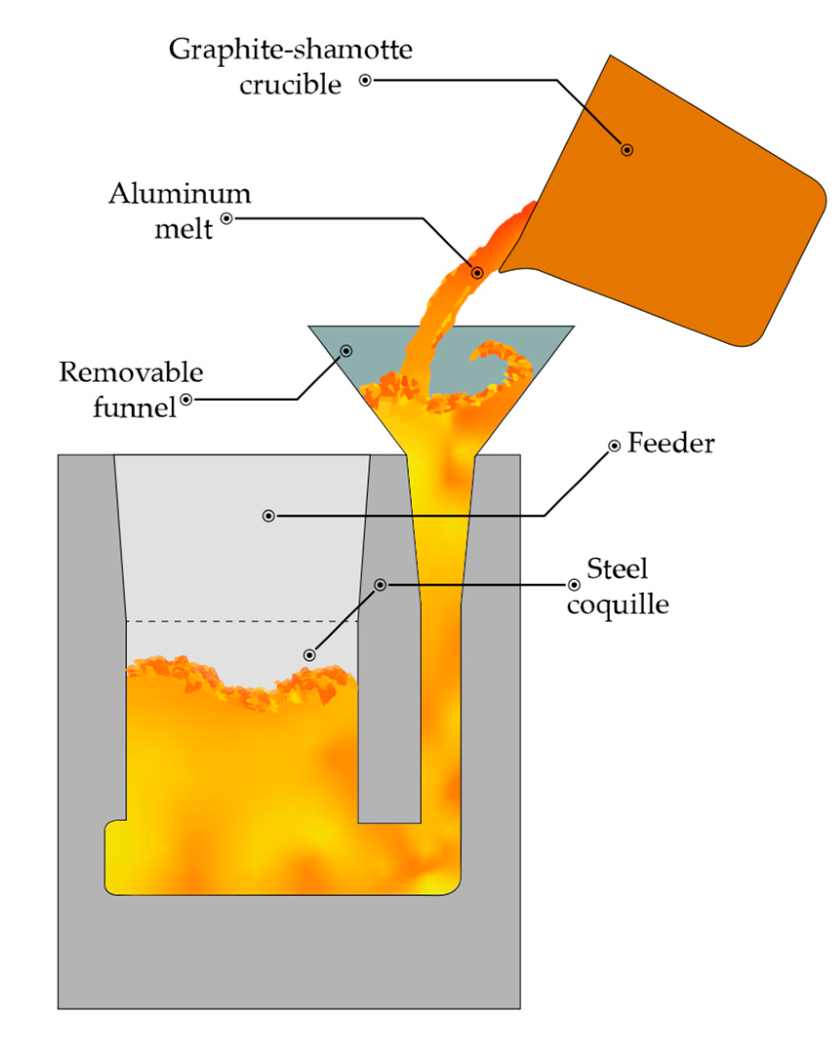
2. Materials and Methods
3. Results and Discussion
4. Conclusions
Author Contributions
Funding
Data Availability Statement
Acknowledgments
Conflicts of Interest
References
- Zhang, L.; Eskin, D.G.; Miroux, A.; Katgerman, L. Formation of Microstructure in Al-Si Alloys Under Ultrasonic Melt Treatment. Light Met. 2012, 2012, 999–1004. [Google Scholar] [CrossRef]
- Zakharov, V.V. Effect of Scandium on the Structure and Properties of Aluminum Alloys. Met. Sci. Heat Treat. 2003, 45, 246–253. [Google Scholar] [CrossRef]
- Zhou, S.; Zhang, Z.; Li, M.; Pan, D.; Su, H.; Du, X.; Li, P.; Wu, Y. Effect of Sc on microstructure and mechanical properties of as-cast Al–Mg alloys. Mater. Des. 2016, 90, 1077–1084. [Google Scholar] [CrossRef]
- Zhou, S.; Zhang, Z.; Li, M.; Pan, D.; Su, H.; Du, X.; Li, P.; Wu, Y. Correlative characterization of primary particles formed in as-cast Al-Mg alloy containing a high level of Sc. Mater. Charact. 2016, 118, 85–91. [Google Scholar] [CrossRef]
- Hansen, N. Hall–Petch relation and boundary strengthening. Scr. Mater. 2004, 51, 801–806. [Google Scholar] [CrossRef]
- Zhang, Z.; Chen, D.L. Contribution of Orowan strengthening effect in particulate-reinforced metal matrix nanocomposites. Mater. Sci. Eng. A 2008, 483, 148–152. [Google Scholar] [CrossRef]
- Buranova, Y.; Kulitskiy, V.; Peterlechner, M.; Mogucheva, A.; Kaibyshev, R.; Divinski, S.; Wilde, G. Al3(Sc,Zr)-based precipitates in Al–Mg alloy: Effect of severe deformation. Acta Mater. 2017, 124, 210–224. [Google Scholar] [CrossRef]
- Sitdikov, O.; Garipova, R.; Avtokratova, E.; Mukhametdinova, O.; Markushev, M. Effect of temperature of isothermal multidirectional forging on microstructure development in the Al-Mg alloy with nano-size aluminides of Sc and Zr. J. Alloys Compd. 2018, 746, 520–531. [Google Scholar] [CrossRef]
- Tang, L.; Peng, X.; Huang, J.; Ma, A.; Deng, Y.; Xu, G. Microstructure and mechanical properties of severely deformed Al-Mg-Sc-Zr alloy and their evolution during annealing. Mater. Sci. Eng. A 2018, 754, 295–308. [Google Scholar] [CrossRef]
- Jiang, F.; Zhou, J.; Huang, H.; Qu, J. Characterisation of microstructure and mechanical properties in Al–Mg alloy with addition of Sc and Zr. Mater. Res. Innov. 2014, 18, S4-228–S4-234. [Google Scholar] [CrossRef]
- Li, M.; Pan, Q.; Shi, Y.; Sun, X.; Xiang, H. High strain rate superplasticity in an Al–Mg–Sc–Zr alloy processed via simple rolling. Mater. Sci. Eng. A 2017, 687, 298–305. [Google Scholar] [CrossRef]
- Malopheyev, S.; Kulitskiy, V.; Mironov, S.; Zhemchuzhnikova, D.; Kaibyshev, R. Friction-stir welding of an Al–Mg–Sc–Zr alloy in as-fabricated and work-hardened conditions. Mater. Sci. Eng. A 2014, 600, 159–170. [Google Scholar] [CrossRef]
- Pan, D.; Zhou, S.; Zhang, Z.; Li, M.; Wu, Y. Effects of Sc(Zr) on the microstructure and mechanical properties of as-cast Al–Mg alloys. Mater. Sci. Technol. 2017, 33, 751–757. [Google Scholar] [CrossRef]
- Xu, C.; Xiao, W.; Zheng, R.; Hanada, S.; Yamagata, H.; Ma, C. The synergic effects of Sc and Zr on the microstructure and mechanical properties of Al–Si–Mg alloy. Mater. Des. 2015, 88, 485–492. [Google Scholar] [CrossRef]
- Zhang, W.; Liu, Y.; Yang, J.; Dang, J.; Xu, H.; Du, Z. Effects of Sc content on the microstructure of As-Cast Al-7wt.% Si alloys. Mater. Charact. 2012, 66, 104–110. [Google Scholar] [CrossRef]
- Kim, M.; Hong, Y.; Cho, H. The effects of Sc on the microstructure and mechanical properties of hypo-eutectic Al–Si alloys. Met. Mater. Int. 2004, 10, 513–520. [Google Scholar] [CrossRef]
- Srinivas, D.; Gowrishankar, M.C.; Hiremath, P.; Sharma, S.; Shettar, M.; PK, J. Influence of various trace metallic additions and reinforcements on A319 and A356 alloys—A review. Cogent Eng. 2022, 9, 2007746. [Google Scholar] [CrossRef]
- Muhammad, A.; Xu, C.; Xuejiao, W.; Hanada, S.; Yamagata, H.; Hao, L.; Chaoli, M. High strength aluminum cast alloy: A Sc modification of a standard Al–Si–Mg cast alloy. Mater. Sci. Eng. A 2014, 604, 122–126. [Google Scholar] [CrossRef]
- Pramod, S.; Ravikirana; Rao, A.P.; Murty, B.; Bakshi, S.R. Effect of Sc addition and T6 aging treatment on the microstructure modification and mechanical properties of A356 alloy. Mater. Sci. Eng. A 2016, 674, 438–450. [Google Scholar] [CrossRef]
- Xu, C.; Xiao, W.; Hanada, S.; Yamagata, H.; Ma, C. The effect of scandium addition on microstructure and mechanical properties of Al–Si–Mg alloy: A multi-refinement modifier. Mater. Charact. 2015, 110, 160–169. [Google Scholar] [CrossRef]
- Qian, H.; Zhu, D.; Hu, C.; Jiang, X. Effects of Zr Additive on Microstructure, Mechanical Properties, and Fractography of Al-Si Alloy. Metals 2018, 8, 124. [Google Scholar] [CrossRef] [Green Version]
- Zuo, M.; Jiang, K.; Liu, X. Refinement of hypereutectic Al–Si alloy by a new Al–Zr–P master alloy. J. Alloys Compd. 2010, 503, L26–L30. [Google Scholar] [CrossRef]
- Czerwinski, F. Cerium in aluminum alloys. J. Mater. Sci. 2020, 55, 24–72. [Google Scholar] [CrossRef]
- Ahmad, R.; Asmael, M.B.A. Influence of Lanthanum on Solidification, Microstructure, and Mechanical Properties of Eutectic Al-Si Piston Alloy. J. Mater. Eng. Perform. 2016, 25, 2799–2813. [Google Scholar] [CrossRef]
- Voron, M.M.; Pruss, M.F.; Byba, O.Y. Microalloying and Modification of Cast Aluminum Alloys for Increasing their Level of Exploitation Properties at Elevated Temperatures. A Review. Foundry Process. Technol. Mater. 2021, 145, 61–68. [Google Scholar] [CrossRef]
- Nogita, K.; McDonald, S.D.; Dahle, A.K. Eutectic Modification of Al-Si Alloys with Rare Earth Metals. Mater. Trans. 2004, 45, 323–326. [Google Scholar] [CrossRef] [Green Version]
- Hosseinifar, M.; Malakhov, D.V. Effect of Ce and La on microstructure and properties of a 6xxx series type aluminum alloy. J. Mater. Sci. 2008, 43, 7157–7164. [Google Scholar] [CrossRef]
- Pourbahari, B.; Emamy, M.; Lotfpour, M.; Allameh, S.H. Effects of La intermetallics on the structure and tensile properties of thin section gravity die-cast A357 Al alloy. In Proceedings of the International Conference on Chemical, Metallurgy and Environmental Engineering (ICMAEE ‘15), Phuket, Thailand, 20–21 December 2015; pp. 296–303. [Google Scholar] [CrossRef] [Green Version]
- Lin, S.; Nie, Z.; Huang, H.; Li, B. Annealing behavior of a modified 5083 aluminum alloy. Mater. Des. 2010, 31, 1607–1612. [Google Scholar] [CrossRef]
- Khrustalyov, A.P.; Kozulin, A.A.; Zhukov, I.A.; Nikitin, P.Y.; Sachkov, V.I.; Vorozhtsov, A.B. Effect of Al3Er Particles on the Structure, Mechanical Properties, and Fracture of AA5056 Alloy After Casting and Deformation Treatment. JOM 2021, 73, 3858–3865. [Google Scholar] [CrossRef]
- Singh, Y. Rare Earth Element Resources: Indian Context; Springer: Berlin/Heidelberg, Germany, 2020; p. 388. [Google Scholar] [CrossRef]
- Mathur, V.; Subramanya, R.P.B.; Manjunath, P.G.C.; Shettigar, A.K. Reinforcement of titanium dioxide nanoparticles in aluminium alloy AA 5052 through friction stir process. Adv. Mater. Process. Technol. 2019, 5, 329–337. [Google Scholar] [CrossRef] [Green Version]
- Lekatou, A.; Karantzalis, A.; Evangelou, A.; Gousia, V.; Kaptay, G.; Gácsi, Z.; Baumli, P.; Simon, A. Aluminium reinforced by WC and TiC nanoparticles (ex-situ) and aluminide particles (in-situ): Microstructure, wear and corrosion behaviour. Mater. Des. 2015, 65, 1121–1135. [Google Scholar] [CrossRef]
- Chen, B.; Zhou, X.; Zhang, B.; Kondoh, K.; Li, J.; Qian, M. Microstructure, tensile properties and deformation behaviors of aluminium metal matrix composites co-reinforced by ex-situ carbon nanotubes and in-situ alumina nanoparticles. Mater. Sci. Eng. A 2020, 795, 139930. [Google Scholar] [CrossRef]
- Mousavian, R.T.; Khosroshahi, R.A.; Yazdani, S.; Brabazon, D.; Boostani, A. Fabrication of aluminum matrix composites reinforced with nano- to micrometer-sized SiC particles. Mater. Des. 2016, 89, 58–70. [Google Scholar] [CrossRef] [Green Version]
- Vorozhtsov, S.; Zhukov, I.; Promakhov, V.; Naydenkin, E.; Khrustalyov, A.; Vorozhtsov, A. The Influence of ScF3 Nanoparticles on the Physical and Mechanical Properties of New Metal Matrix Composites Based on A356 Aluminum Alloy. JOM 2016, 68, 3101–3106. [Google Scholar] [CrossRef]
- Ko, J.M.; Durbin, S.D.; Fukuda, T.; Inaba, K. Nonisomorphic ErF3 layers on Si(111) substrates grown by molecular beam epitaxy. J. Vac. Sci. Technol. A Vac. Surf. Film. 2000, 18, 922–926. [Google Scholar] [CrossRef]
- Kim, Y.-M.; Choi, S.-W.; Hong, S.-K. Influence of Si content on thermal expansion characteristic of Al–Si alloys. Mater. Sci. Technol. 2020, 36, 709–716. [Google Scholar] [CrossRef]
- Vorozhtsov, S.; Minkov, L.; Dammer, V.; Khrustalyov, A.; Zhukov, I.; Promakhov, V.; Vorozhtsov, A.; Khmeleva, M. Ex Situ Introduction and Distribution of Nonmetallic Particles in Aluminum Melt: Modeling and Experiment. JOM 2017, 69, 2653–2657. [Google Scholar] [CrossRef]
- Elibrary. Science Digital Library. Available online: https://www.elibrary.ru/item.asp?id=43877731 (accessed on 15 June 2023).
- Wang, E.; Hui, X.; Wang, S.; Zhao, Y.; Chen, G. Improved mechanical properties in cast Al–Si alloys by combined alloying of Fe and Cu. Mater. Sci. Eng. A 2010, 527, 7878–7884. [Google Scholar] [CrossRef]
- Dinnis, C.M.; Taylor, J.A.; Dahle, A.K. As-cast morphology of iron-intermetallics in Al–Si foundry alloys. Scr. Mater. 2005, 53, 955–958. [Google Scholar] [CrossRef]
- Khan, M.; Das, A.; Li, Z.; Kotadia, H. Effects of Fe, Mn, chemical grain refinement and cooling rate on the evolution of Fe intermetallics in a model 6082 Al-alloy. Intermetallics 2021, 132, 107132. [Google Scholar] [CrossRef]
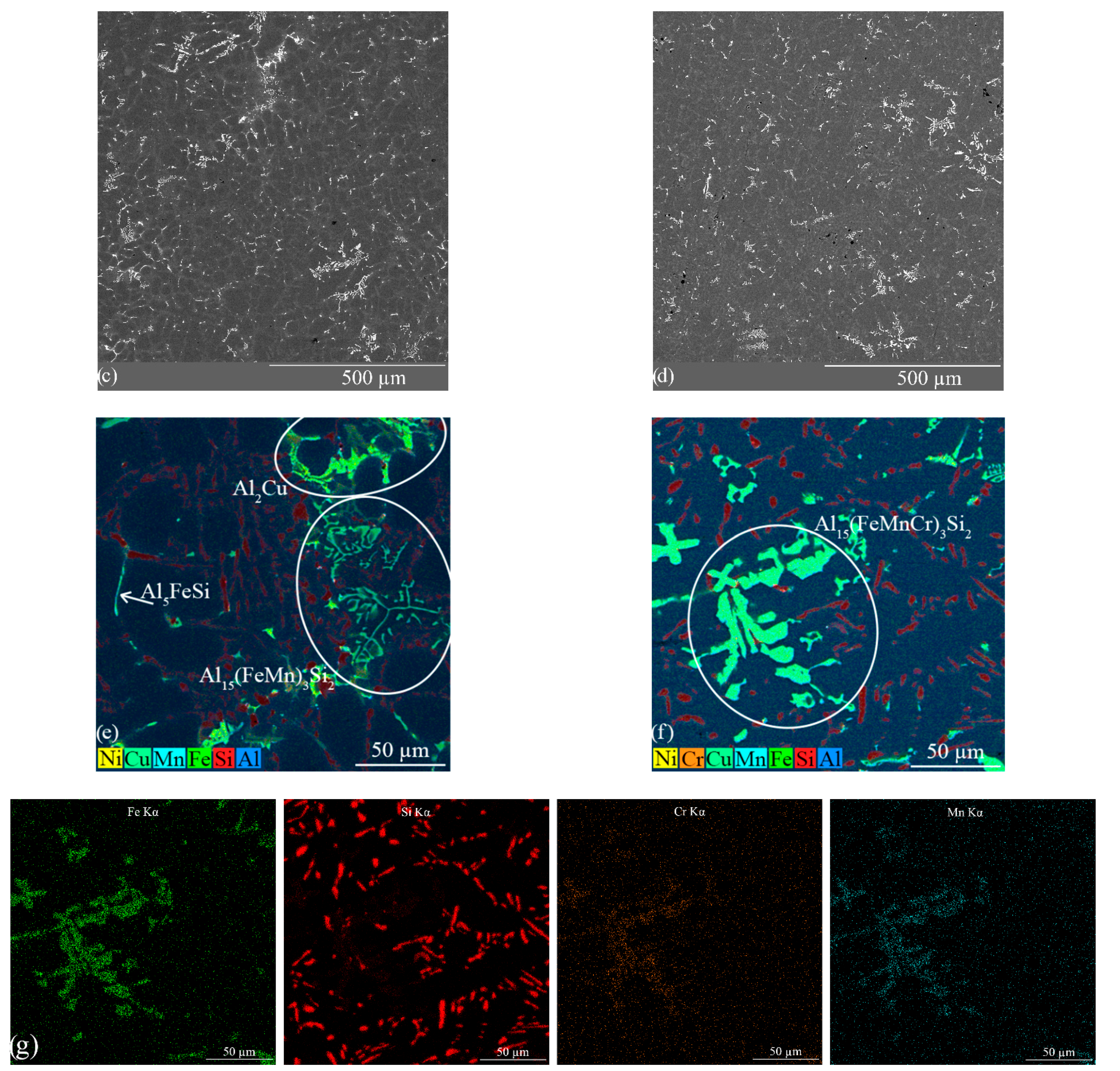
- Liu, B.; Ma, C.; Li, L.; Yang, C.; Yu, N.; Wang, W.; Gao, T. Morphologies and Compositions of α–Al15Fe3Si2-Type Intermetallics in Al–Si–Fe–Mn–Cr Alloys. Int. J. Met. 2023, 71, 1156–1164. [Google Scholar] [CrossRef]
- Khrustalyov, A.P.; Akhmadieva, A.; Monogenov, A.N.; Zhukov, I.A.; Marchenko, E.S.; Vorozhtsov, A.B. Study of the Effect of Diamond Nanoparticles on the Structure and Mechanical Properties of the Medical Mg–Ca–Zn Magnesium Alloy. Metals 2022, 12, 206. [Google Scholar] [CrossRef]


| Phase | Volume Fraction, Mas. % | Lattice Parameters, Å | CSR Dimensions, nm | Microdistortions, ∆d/d |
|---|---|---|---|---|
| ErF3_62 | a = 6.3437 | 18 | 2.2 × 10⁻³ | |
| 100 | b = 6.8863 | |||
| c = 4.3935 |
| Al | Si | Fe | Mn | Mg | Er | |
|---|---|---|---|---|---|---|
| A359 | 86.21–91.49 | 8.65–10.67 | 0.08–0.13 | 0.19–0.32 | 0.18–0.32 | – |
| A359 + ErF3 | 86.66–90.15 | 9.55–10.81 | 0.08–1.09 | 0.21–0.40 | 0.18–0.22 | 0.61–0.81 |
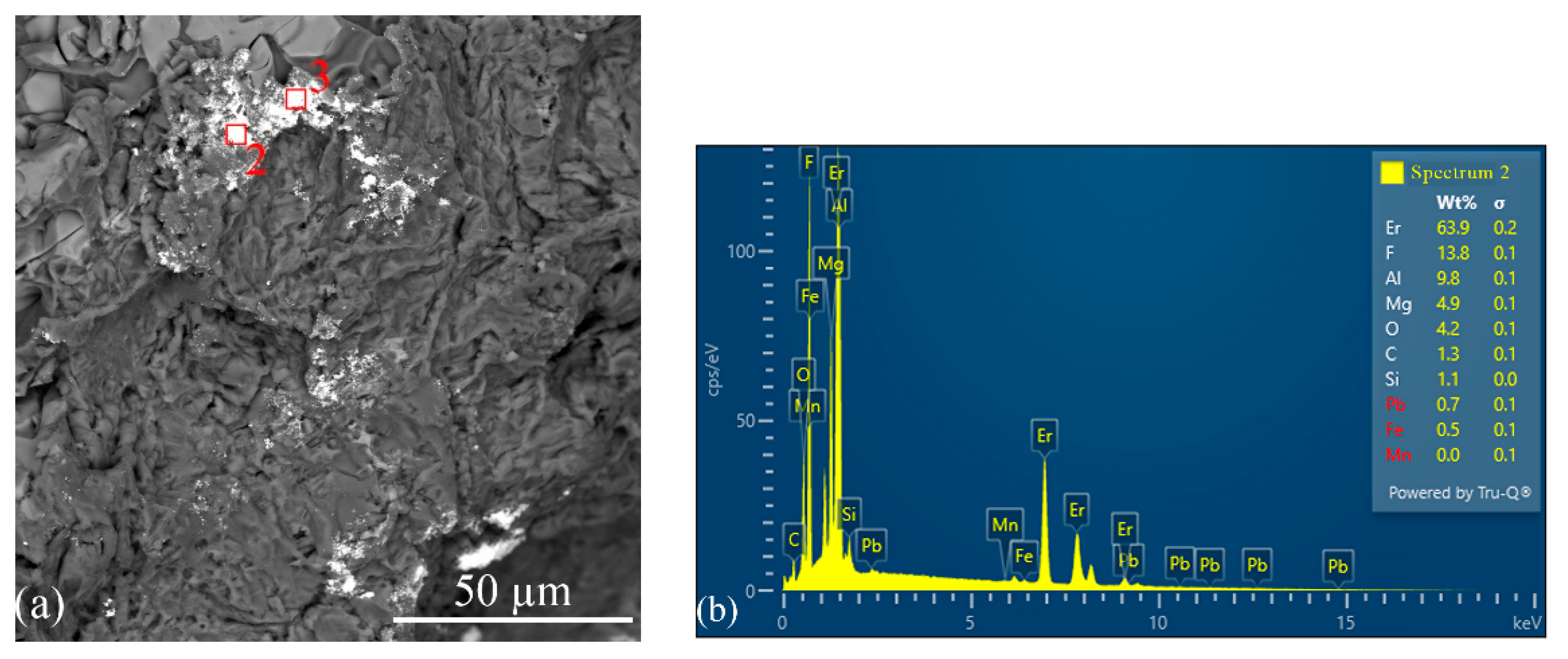
| Label | Al | Fe | Mn | Cr | Si | Er | F | Mg | C | O | Cu |
|---|---|---|---|---|---|---|---|---|---|---|---|
| 1 | 63.72 | 1.4 | 0 | 0 | 4.9 | 12.7 | 8.88 | 2.2 | 1.13 | 4.17 | 0.9 |
| 2 | 65.57 | 13.76 | 3.94 | 1.60 | 12.31 | 0 | 0.24 | 0.14 | 0.85 | 0.42 | 1.17 |
| 3 | 13.04 | 0.5 | 0 | 0 | 2.18 | 71.76 | 6.56 | 0.13 | 1.29 | 4.54 | 0 |
| 4 | 9.77 | 0.56 | 0 | 0 | 1.21 | 64.39 | 13.69 | 4.95 | 1.28 | 4.15 | 0 |
| Alloy | HB | HV(Al) | HV(Si) | HV(β(Al5)) | HV(αm(Al15)) | HV(αm(Al15) + Cr) |
|---|---|---|---|---|---|---|
| A359 | 86.3 ± 2.6 | 81.8 ± 6 | 92.7 ± 12 | 98.6 ± 6 | 107.6 ± 23 | 230 ± 98 |
| A359 + ErF3 | 84.9 ± 4.2 | 83.5 ± 6 | 95.3 ± 8 | 95.4 ± 6 | 143.9 ± 29 | 245 ± 68 |
| A359 (T6) | 118.6 ± 3.5 | 117.8 ± 6 | 134.7 ± 18 | 128 ± 8 | 153.2 ± 14 | 181 ± 68 |
| A359 + ErF3 (T6) | 118.1 ± 4.5 | 117.3 ± 7 | 135 ± 13 | 123 ± 8 | 163 ± 14 | 190 ± 55 |
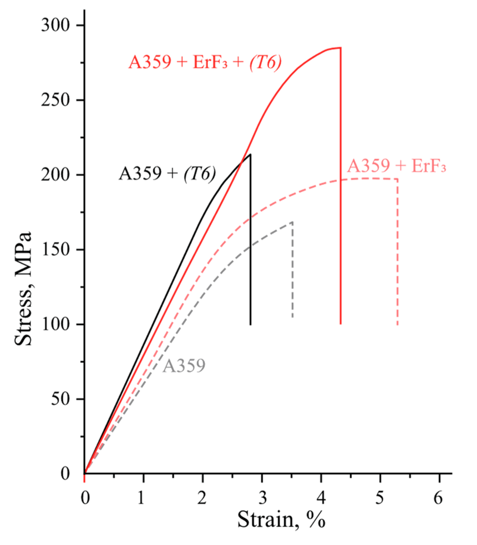
| Alloy | State | σ0.2, MΠa | σB, MΠa | εmax, % | δ, % |
|---|---|---|---|---|---|
| A359 | As-cast | 142 ± 7 | 168 ± 11 | 3.5 ± 0.8 | 0.7 ± 0.2 |
| A359 + ErF3 | 162 ± 8 | 195 ± 13 | 4.9 ± 1 | 2.3 ± 0.3 | |
| A359 | (T6) | 197 ± 6 | 213 ± 13 | 2.5 ± 0.4 | 0.3 ± 0.1 |
| A359 + ErF3 | 267 ± 7 | 286 ± 13 | 4.3 ± 0.4 | 0.8 ± 0.2 |
Disclaimer/Publisher’s Note: The statements, opinions and data contained in all publications are solely those of the individual author(s) and contributor(s) and not of MDPI and/or the editor(s). MDPI and/or the editor(s) disclaim responsibility for any injury to people or property resulting from any ideas, methods, instructions or products referred to in the content. |
© 2023 by the authors. Licensee MDPI, Basel, Switzerland. This article is an open access article distributed under the terms and conditions of the Creative Commons Attribution (CC BY) license (https://creativecommons.org/licenses/by/4.0/).
Share and Cite
Kakhidze, N.; Valikhov, V.; Selikhovkin, M.; Khrustalyov, A.; Zhukov, I.; Vasiliev, S.; Vorozhtsov, A. Effects of ErF3 Particles on the Structure and Physicomechanical Properties of A359 Alloy. Metals 2023, 13, 1463. https://doi.org/10.3390/met13081463
Kakhidze N, Valikhov V, Selikhovkin M, Khrustalyov A, Zhukov I, Vasiliev S, Vorozhtsov A. Effects of ErF3 Particles on the Structure and Physicomechanical Properties of A359 Alloy. Metals. 2023; 13(8):1463. https://doi.org/10.3390/met13081463
Chicago/Turabian StyleKakhidze, Nikolai, Vladimir Valikhov, Mikhail Selikhovkin, Anton Khrustalyov, Ilya Zhukov, Sergey Vasiliev, and Alexander Vorozhtsov. 2023. "Effects of ErF3 Particles on the Structure and Physicomechanical Properties of A359 Alloy" Metals 13, no. 8: 1463. https://doi.org/10.3390/met13081463