Article

Statistical Analysis of Tribological Properties of Mg(AM50)/GNF-Al2O3sf Hybrid Composites

1
School of Interdisciplinary, Department of Advanced Innovative Manufacturing Engineering, Pusan National University, Busan 46241, Republic of Korea
2
ERC-NSDM, School of Mechanical Engineering, Pusan National University, Busan 46241, Republic of Korea
*
Author to whom correspondence should be addressed.
Metals 2023, 13(8), 1418; https://doi.org/10.3390/met13081418
Submission received: 23 April 2023 / Revised: 9 July 2023 / Accepted: 21 July 2023 / Published: 8 August 2023
(This article belongs to the Topic Metal Matrix Composites: Recent Advancements)

Abstract

:
The present article describes the tribological properties of Mg-based hybrid composites reinforced with graphite nanofiber (GNF) and alumina short fiber (Al2O3sf) that were investigated. The Mg/GNF/Al2O3sf hybrid composites with varying volume fraction of fiber (10 vol.%, 15 vol.%, 20 vol.%) were developed. SEM observations indicate that the GNF cluster distributions within the array of the Al2O3sf network are found to be relatively good. The Taguchi design of the experiment has been applied to conduct the wear test, and the statistical analysis of variance (ANOVA) has been used to evaluate the influence of wear test parameters on the wear loss and coefficient of friction (COF) of the composites. The influence of wear test parameters such as volume fraction of fiber (VF), applied load (AL), sliding distance (SD), and sliding speed (SP) on the wear loss and COF of composites was analyzed under dry sliding conditions. The results of ANOVA indicate that the sliding distance was found to be the prominent factor affecting wear loss, and the applied load influenced the COF most significantly. Furthermore, the composites with 20 vol.% of fiber had lower wear loss than those with 10 vol.% and 15 vol.% of fiber. The COF of composites with 15 vol.% of fiber was found to be slightly lower compared to the 10 vol.% and 20 vol.% of fiber cases. The results imply that the hybridization of GNFs and Al2O3sf, as well as the formation of Mg17Al12 and Al2MgC2 precipitates enhanced the tribological properties of the Mg hybrid composites.

1. Introduction

Metal matrix nanocomposites offer significant mechanical and multifunctional performance benefits for engineering applications [1]. Magnesium-based composites have higher wettability to carbon compared to aluminum alloy, provided that they are sufficiently graphitized [2]. However, fiber reinforced Mg-based composites sometimes exhibit inferior tribological properties [3]. Therefore, in order to improve the tribological properties, the shape and size of the reinforcement must be considered as design parameters and also to modify the architecture of the composite system, i.e., hybrid composites. Normally, hybridization of reinforcements has gained importance in order to enhance the properties of composites [4]. The wear resistance of composites has been found to be improved by hybridization with particles, whiskers, and nanoparticles. Moreover, nano-scale sized reinforcements are typically added to enhance the properties of magnesium-based composites [5,6,7,8]. However, it is difficult to disperse nanofibers in metal melts due to their high viscosity, poor wettability, and a large surface to volume ratio [9]. The principal problem with nanofiber is to retain its integrity and shape during the development of composites. If a hybrid network is used, the problem with nanofibers can be reasonably solved. Hence, there is a need for the development of hybrid preform using alumina short fibers (Al2O3sf) and graphite nanofibers (GNFs). In such hybrid preforms, an array of Al2O3sfcan be used to disperse the GNFs. Muhammet Emre Turan et al. [10] found that the wear properties of the AZ91 alloy were improved with the hybridization of MWCNTs and GNPs. Yashar behnamian, et al. [11] studied the wear properties of ZK60-matrix composites reinforced with hybrid MWCNTs and B4C particles. The results showed that by increasing MWCNTs up to 0.5 wt%, the wear rate was decreased and the plastic deformation was postponed. The dry sliding wear properties of the AZ91 alloy-based composite reinforced with TiO2 and graphene were reported by Jayabharathy et al. [12]. They found that wear loss was lower for hybrid composites than that of the unreinforced AZ91 alloy. As reported by Aatthisugan et al. [13], the increase in wear resistance of the magnesium hybrid composites studied was attributed to the presence of B4C and graphite particles. Dehong Lu et al. [14] found an improvement in the wear properties of the AZ31 magnesium alloy by hybridization with 0.2%CNT and 0.1%Al2O3 reinforcements.
The Taguchi method of experimental design provides a simple, efficient, and systematic approach compared to other statistical methods [15]. The Taguchi technique is applied for optimization of process parameters and the determination of their effects on target parameters. Jayasathyakawin et al. [16] reported the effects of ZnO addition on the wear properties of Mg−Al matrix composites by using the Taguchi method. They found that the applied load significantly affected the wear rate, but with respect to COF, ZnO reinforcement inclusion affected the COF when compared with the load. Optimization of the dry sliding wear behavior of SiN and Gr reinforced Al composites using the Taguchi method was reported by Ashish kumar [17]. ANOVA results revealed that load is the influencing factor in wear rate, followed by the sliding velocity and the percentage of graphite. Girish BM et al. [18] investigated the wear behavior of AZ91/SiC/Gr hybrid composites using the Taguchi technique. S/N ratio and analysis of variance were used to investigate the influence of the parameters on the wear rate of composites.
Based on the literature, it is seen that studies on the tribological properties of Mg hybrid composites are limited. There has been no attempt made to study the tribological properties of the Mg/GNF/Al2O3sf hybrid composites using the Taguchi technique. Therefore, in the present work, the contribution of wear test parameters such as volume fraction of fiber (VF), applied load (AL), sliding distance (SD), and sliding speed (SP) on the tribological properties (typically wear loss and coefficient of friction) of composites was investigated. The experiments were performed according to the design of experiment using the Taguchi method. A scanning electron microscope (SEM) was used to examine the microstructure of the developed Mg hybrid composites, and wear worn surfaces after being wear tested.

2. Materials and Methods

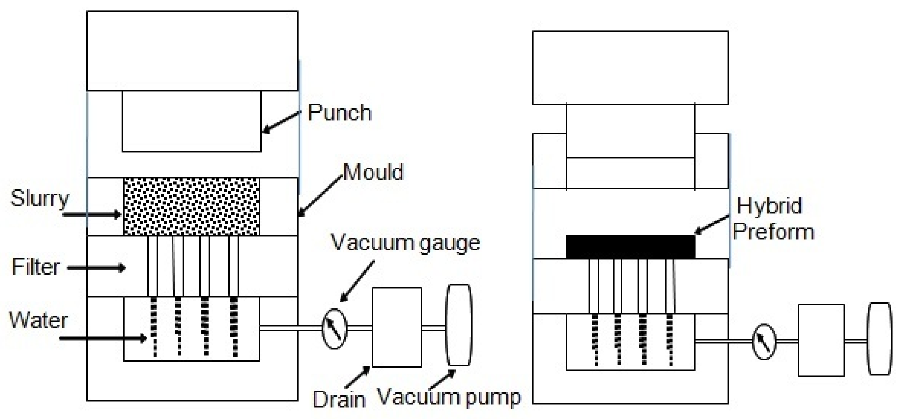
2.1. Materials and Fabrication of Mg/GNFs/Al2O3sf Hybrid Composites

The properties of the reinforcements of GNF and Al2O3sf are presented in Table 1. The hybrid preform using GNFs and Al2O3sf was fabricated using various total volume fractions of fibers, such as 10 vol.%, 15 vol.%, and 20 vol.%. The volume percentage of GNFs and Al2O3sf were maintained as 30% and 70%, respectively. The schematic diagram for the fabrication of the preform is shown in Figure 1. Initially, Al2O3sf and GNFs were mixed in the selected ratio with distilled water and the required amount of binder (10%). The level of mechanical agitation was carefully controlled to avoid the damage to the Al2O3sf and GNFs. Then, cationic polyacrylamide, NaDDBs, and starch (5% each of the total weight of fibers) were added. Subsequently, ultrasonic agitation was employed for a proper mixing of the additives in the distilled water medium. By using a vacuum pump the water was removed and the preforms were pressed by a punch to the desired thickness. Thereafter, the fabricated preforms were taken from the mold and baked at 200 °C. Finally, laboratory scale hybrid preformswith lengths of 60 mm, widths of 20 mm, and thicknesses of 15 mm were developed successfully. The details of the fabrication of hybrid preform and its mechanical properties have been described elsewhere [19].
The AM50 alloy is used as the matrix for developing the Mg hybrid composites, and its chemical composition is listed in Table 2. In the present work, we develop Mg-based hybrid composites reinforced with GNF/Al2O3sf using the infiltration method. Initially, the GNF/Al2O3sf hybrid preform was preheated to a temperature of 400 °C, and the mold was preheated to 300 °C. The preheated GNF/Al2O3sf hybrid preform was placed in the mold, and then molten magnesium alloy was poured into the preform. The pouring temperature of the magnesium alloy was 700 °C, and a pressure of 3 MPa was applied with a punch velocity of 7 kN/s and a holding time of 30 s. The magnesium melt was successfully infiltrated into the GNF/Al2O3sf hybrid preform using the squeeze casting method. In order to prepare the metallographic specimen for SEM analysis, the samples were mounted on an epoxy mounting medium, and subjected to a wet grinding sequence using silicon carbide papers with grit sizes of 240, 400, 600, 800, and 1200. Then, the specimen was dipped into the etchant (HF + HNO3 in 100 mL of water) for 5 s, washed in water, and then air blow dried. SEM was used to examine the microstructure of the developed Mg hybrid composites. The details of the fabrication of Mg-GNF/Al2O3sf hybrid composites has been explained in the authors’ earlier article [20].

2.2. Wear Test of Mg Hybrid Composites

The wear tests were performed using a pin-on-disc type wear machine (Figure 2) under dry sliding conditions, and COF was continuously measured during the test. The pin-on-disc wear test is carried out according to the ASTM G99 standards. The composite specimens with dimensions of 18 × 8 mm and stainless steel (SUS-304) with a diameter of 50 mm counter parts were used for the wear test at room temperature. The initial weight of the specimen was measured in an electronic weighting machine with an accuracy of 0.001 gm. The wear test experiments were performed according to the design of experiments using the Taguchi method. In the Taguchi method, a design parameter is considered significant if its influence is large compared to the experimental error as estimated by the ANOVA (analysis of variance) statistical method. The wear volume loss was calculated using wear depth, wear width, and stroke length. The wear width was measured with a microscope, and the volume loss was calculated as the wear area multiplied by the stroke length. Therefore, the wear volume loss was calculated using Equation (1) [21].
V L = 2 3 a . b . c   [ m m 3 ]
where VL is the volume loss, a is the wear depth, b is the wear width, and c is the stroke length.
In this study, the wear testing parameters such as volume fraction of fiber (VF), applied load (AL), sliding speed (SP), and sliding distance (SD) were studied using L9 orthogonal arrays at three levels, as shown in Table 3. The wear tests were carried out under the Taguchi design of experimental conditions given in Table 4. In addition, mean response graphs were plotted using the software ANVW-31 (version 1.0) and the percentage of control parameters were determined by the ANOVA method. According to the ANOVA, a lower value is considered to be the better value in the signal to noise (S/N) ratio in the Taguchi method.
Based on the S/N ratio results, it can be determined which control factor has the highest impact on the wear loss and COF of composites. The S/N ratio is determined by using the following Equation (2).
S N = 10 log 1 n i = 1 n y i 2
where ‘n’ is the number of repetitions and y are the data of experimental results.

3. Results

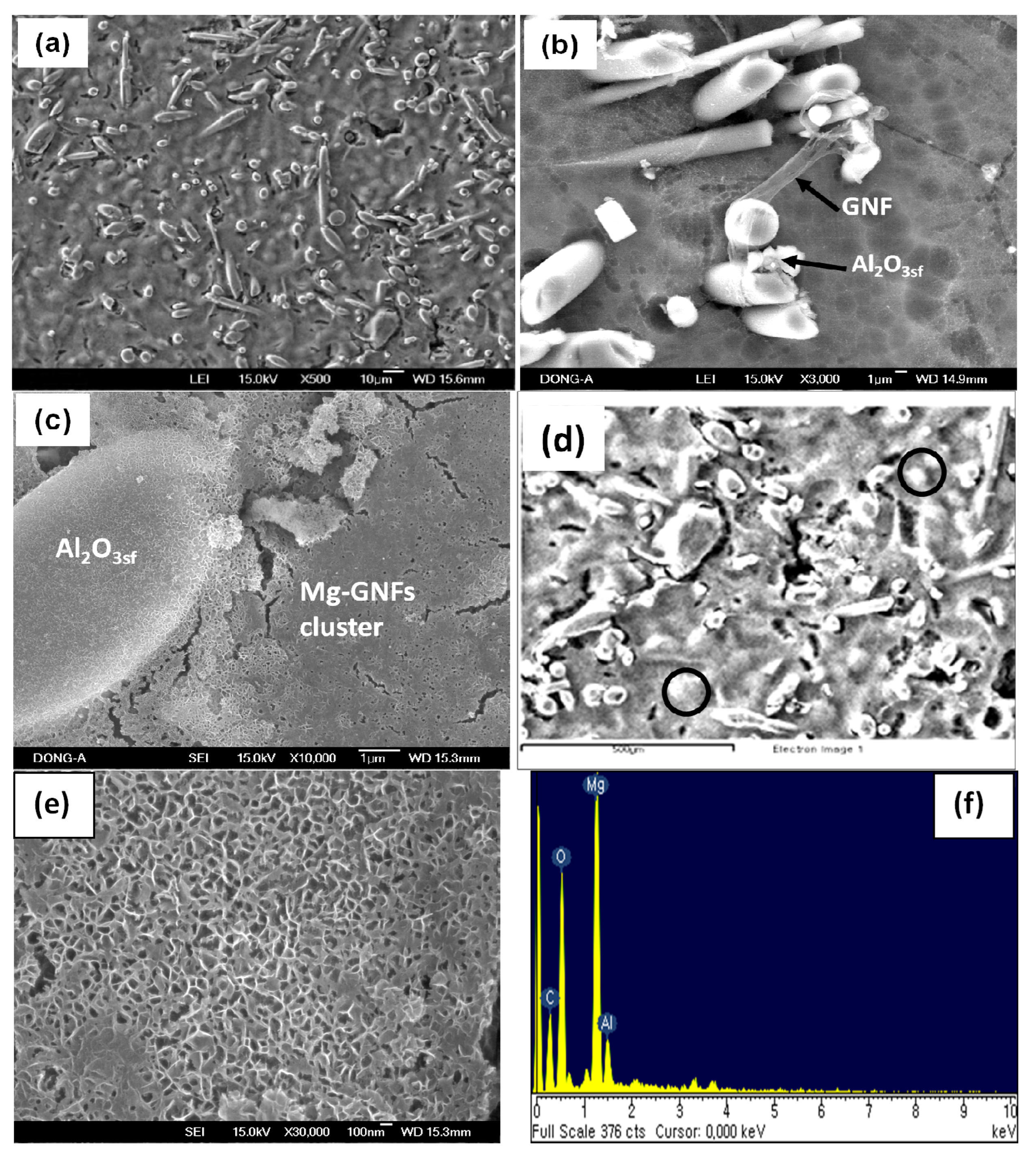
3.1. SEM Analysis of Hybrid Preform

The microstructure of the hybrid preform was examined by SEM technique (JEOL 2000-FX). Typical SEM images shown in Figure 3a,b indicate that the Al2O3sf and GNF cluster are well dispersed in the hybrid preform. The array of the Al2O3sf network has been found to help the GNF clusters is being well distributed within the hybrid preform. This could also improve the infiltration behavior of the hybrid preform with Mg melts. The GNF cluster and Al2O3sf are bonded in a better manner within the hybrid preform, as shown in Figure 3b. The bonding of GNF cluster and Al2O3sf assists the hybrid preform in withstanding the operating pressure during the infiltration of Mg melts. The typical EDX analysis of the GNF cluster is shown in Figure 3c, and the intensity profile of carbon indicates the GNF cluster present in the Al2O3sf network.The Si peaks observed in the profiles clearly indicate the presence of the silica binder at the interfaces, leading to a fine bonding of GNFs and Al2O3sf during preforming.

3.2. SEM Analysis of Mg Hybrid Composites
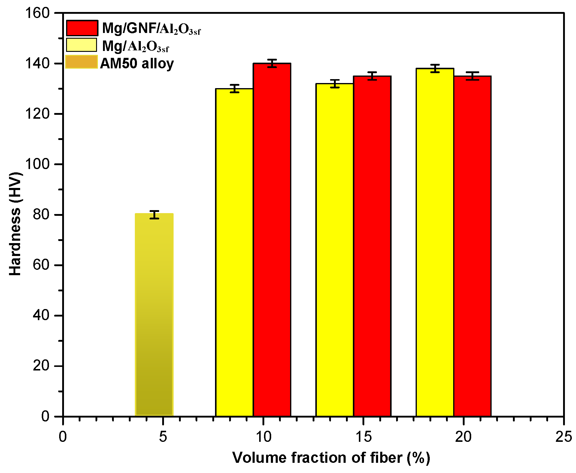
Figure 4a shows a SEM image of Mg hybrid composite. The sample exhibits a relatively good distribution of Al2O3sf with a very small interfiber spacing. It is clearly seen that GNF clusters are well dispersed within the Mg matrix and the molten Mg has been found to wet the reinforcements effectively. This is due to the lower surface tension of molten magnesium leading to an easy penetration into the channels of the hybrid preforms. The SEM characterization reveals a good interfacial integrity between GNF clusters and Mg matrix, as also shown in Figure 4b. It is known that the surface of graphite consists of more basal planes, which are high energy planes. This kind of surface plane can get well bonded with Mg matrix. Due to the good bonding between the GNF and Al2O3sf a better load sharing can be achieved, which can lead to an enhancement of the wear properties of the composites. There is a possibility of Mg17Al12 or MgAl2O4 spinel formation at the interface of the Mg matrix and GNFs [22]. Typical higher magnification of a SEM image of Mg hybrid composite is shown in Figure 4c. It is seen that the GNF clusters are located near the interface of the Mg matrix and Al2O3sf in the composites. Figure 4d shows the presence of Mg17Al12 precipitates (white regions) in the Mg matrix regions. Normally, Mg17Al12 precipitates at the interface can improve the interfacial bonding and it is hard and brittle, which can enhance the wear properties of composites [23]. The higher magnification of Mg infiltrated within the GNF cluster is shown in Figure 4e; it can be seen that the individual GNFs are connected to a network. The EDX profile obtained from the interface area of GNFs and the Mg matrix is shown in Figure 4f, and the small peaks in the profile can be due to the presence of Mg17Al12.

3.3. Micro-Hardness

Figure 5 shows the microhardness of Mg/GNF/Al2O3sf hybrid composites. The hardness evaluation was performed on different regions of the sample using a Vickers hardness tester at load of 100 gf, and an average value was taken. The obtained results show that the hardness of Mg/GNF/Al2O3sf hybrid composite is higher than that of Mg/Al2O3sf. This increase in hardness is due to the better load sharing between GNFs and Al2O3sf within the Mg matrix and is also accounted for in terms of the resistance of dislocation movements caused by adding GNFs [24]. The hardness decreases at higher volume fraction of fiber attributed to the possible indentation near the GNF cluster within the Mg matrix. Moreover, it is expected that residual thermal stresses can be produced at the interfaces due to the thermal mismatch between the GNFs/Al2O3sf and the Mg matrix. This can also contribute to the reduction in the hardness of the composites [25].

3.4. Tribological Propertiesof Mg/GNFs/Al2O3sf Composites

The results show an increase in wear resistance of composites due to the better load bearing of the GNFs/Al2O3sf and Mg matrix. The COF decreases when the threshold VF of 15 vol.% is reached and after that it increases. Furthermore, the GNF clusters reduce the contact between the composite pin and the counterface surface metal. The formation of carbide acts as a barrier to the Mg matrix during abrasive sliding and weakens the worn surface, and it enhanced the wear resistance [26]. The good distribution of GNFs/Al2O3sf within the Mg matrix reduced the shear stress between the contact sliding surfaces, causing a decrease in COF. Due to the presence of GNF cluster, the Al2O3sf are detached from the sliding surface which results in a change in type of wear from three body to two body. Normally, the formation of a limited amount of GNF clusters is beneficial to the mechanical and tribological properties of hybrid composites [27].

3.4.1. Influence of Wear Test Parameters on Wear Loss

The experimental results of the wear tests are shown in Table 5. From the ANOVA analysis, the contribution of the process parameters to the wear loss of the composite has been evaluated. Results of the pooled ANOVA for wear loss are shown in Table 6. The mean-response graphs of the influence of the various process parameters on the wear loss of the composite are shown in Figure 6a. The graphs haves been obtained by using the software ANVW-31. It has been found that the wear loss decreases when the volume fraction is increased from 10% to 15% and then to 20%. The wear loss has been found to be decreased with an increase in sliding speed. The results indicate the formation of a mechanically mixed layer, it covers more area of contact between the specimen and counter surface. Normally, Mg17Al12 precipitate at the interface of Mg matrix and GNF/Al2O3sf, which is hard and brittle, can improve the interfacial bonding and enhance the wear resistance of composites [28]. Moreover, the wear loss increases with an increase in the applied load and sliding distance. This is due to the slip between agglomerated GNFs which can weaken the bonding between Al2O3sf and the matrix metal. It was found out that the contributions of processing parameters such as volume fraction of fibers, applied load, sliding speed, and sliding distance are 12%, 24%, 9%, and 55%, respectively. Thus, the sliding distance has been found to be the most important process parameter controlling the wear loss of the composites.

3.4.2. Influence of Wear Test Parameters on Coefficient of Friction

The results of the pooled ANOVA for the coefficient of friction are shown in Table 7. In Figure 6b, the mean-response graphs are shown, indicating the influence of process parameters on the coefficient of friction of the composites. The coefficient of friction has been found to be reduced when the volume fraction of fiber is increased up to 15%, after that, the friction shows an increasing trend. This occurs due to the local response of the microstructure and it is attributed to the presence of Mg17Al12 or MgAl2O4 phases. The formation of Mg17Al12 precipitate in the Mg/graphite composites has been reported earlier [23]. Furthermore, the coefficient of friction decreases as applied load and sliding speed are increased, as shown in the figure. Therefore, the GNF cluster within the Al2O3sf network influences the lower friction of the composites. Moreover, the presence of MgO is due to the chemical reaction of the Mg matrix and Al2O3sf, and it can also contribute to enhancing the wear properties of composites [29]. The abrasion by the decohesion of the GNF cluster causes a contact between the specimen and counter face; as a result, the surface becomes rough and this leads to an increase in the friction. However, the coefficient of friction is found to be higher with an increase in the sliding distance. The contributions of the volume fraction of fiber, applied load, sliding speed, and sliding distance to the coefficient of friction are 24%, 48%, 15%, and 13%, respectively. It has thus been concluded that the applied load is the most prominent factor influencing the coefficient of friction of hybrid composites.

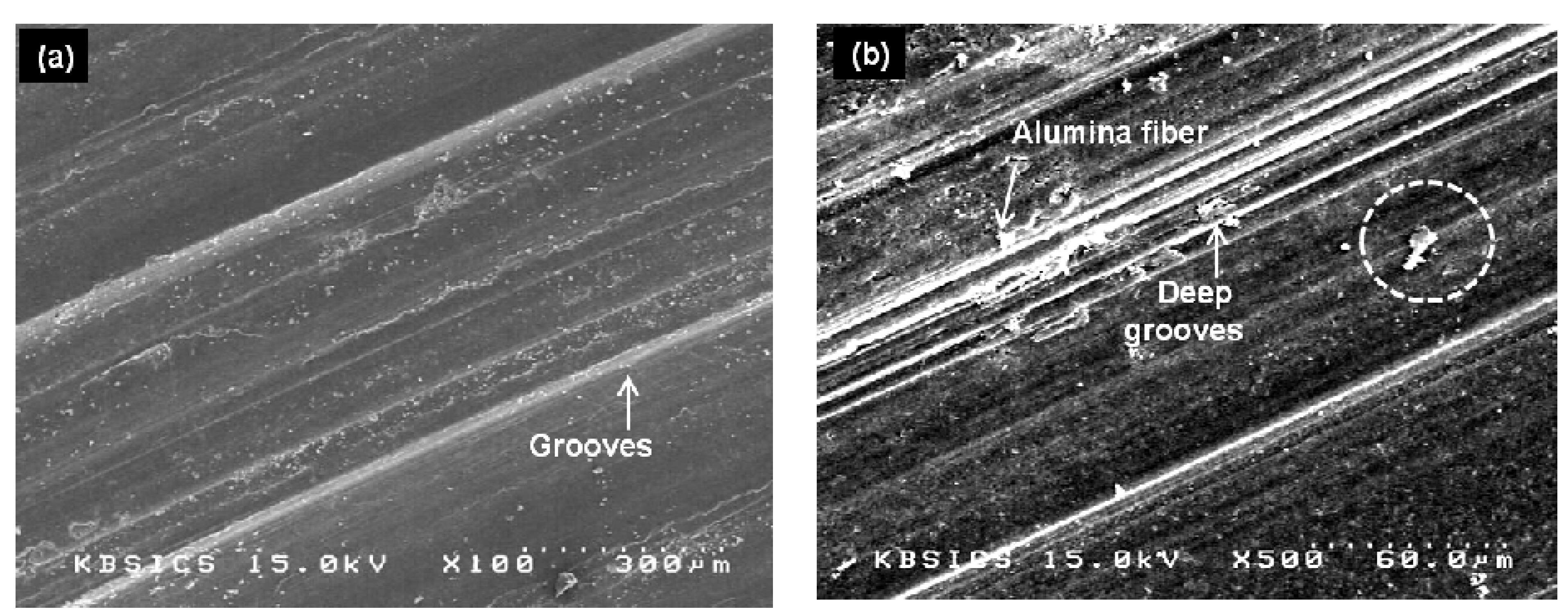
3.4.3. Wear Worn Surface Analysis

Typical SEM images show the wear worn surfaces of the hybrid composites with 10 vol.% testing at 100 N and 500 N (Figure 7). The figure shows the worn surface of composites tested at 100 N; the result of abrasion by bonding of Al2O3sf and GNFs as a slight ploughing can be observed. The material delamination is not severe on the sample, hence, the grooves are finer on the worn surface as shown in Figure 7a. In the case of the sample tested at 500 N wider grooves appeared on the worn surface due to abrasive wear, as a result, the wear loss is higher. In addition, reattachment of wear debris onto the worn surfaces due to higher applied load can be clearly seen (Figure 7b). The increase in applied load resulted in severe plastic deformation of the worn surface in the sliding direction [30]. In the case of hybrid composites with 15 vol.% tested at 100 N and 500 N (Figure 8), the grooves are finer and smaller debris formed on the worn surface. Moreover, the ploughing grooves were observed on the worn surface. This indicates the removal of material by delamination and a mild damage of a worn surface in the composite being found (Figure 8a). The plastic deformation of the matrix can be restricted due to the GNF cluster within the Al2O3sf network, and supports a barrier to the movement of dislocation, resulting in higher wear resistance. This leads to a smoother worn surface and higher degree of sliding action, which result in a reduction of the coefficient of friction. The reattachment of wear debris can also be seen on the worn surface. The adhesive and abrasive wear of the hybrid composites is slighter than that of the mono-composites due to the presence of GNF clusters, which act as self-lubrication material; this effect is induced by carbon and it reduces the coefficient of friction [31]. However, for the worn surface of the composites tested at 500 N a large extent of material flow and a scuffing tendency have been observed (Figure 8b). Moreover, a scar due to plastic deformation by ploughing is observed and the worn surface was severely deformed. Normally, on the worn surface, micro-cracks and voids are induced due to the plastic formation of composites [32].
Figure 9a,b shows the typical SEM images of worn surfaces of composites with 20 vol.% at 100 N and 500 N. At lower load there were signs of the formation of micro-cracks and grooves in the worn surface, but it seems that in some regions agglomerated debris was formed, suggesting that the strain hardening effect induces debris and severe deformation on the surface by ploughing [33]. Furthermore, the worn surface indicates the presence of delamination surfaces and GNF cluster debris, as shown in Figure 9a, which appear to be bonded within the worn surface of the composites. From Figure 9b, it can be clearly seen that the worn surface was a smeared layer due to scuffing, and delaminated craters are more on the surface of the sample tested under higher load. Figure 9c shows that for the EDS analysis of the worn surface the absence of Fe content indicates that the abrasive material transition has been taken place instead of adhesion. In the profile a small peak can observed; this may be due to the presence of the Al2MgC2, which weakens the worn surfaces and results in the enhancement of wear resistance. The percentage of aluminum level is higher than 0.6% and less than 2%, resulting the formation of carbide at the interface of the Mg alloy and graphite fiber [34]. In addition, the fiber fragmentation effect was not observed due to the higher applied load while wear testing. Moreover, when the applied load is low, no plastic deformations occur in the worn surface. This is because of the decreased degree of abrasive wear mechanism during wear testing [35].

4. Conclusions

  • Magnesium (AM50)-based hybrid composites reinforced with GNFs and Al2O3sf were fabricated by using the squeeze casting method. SEM observations indicated that the GNFs and Al2O3sf are well dispersed in the developed hybrid preform. In the Mg matrix, the distribution of GNF clusters within the array of Al2O3sf network is found to be relatively good.
  • The wear properties of Mg/GNF/Al2O3sf hybrid composites were studied using the Taguchi design of experiment. The ANOVA was used to evaluate the contribution of wear test parameters on the wear loss and COF of hybrid composites.
  • The optimum wear test parameter was determined using the S/N ratio, with the smaller the better criteria as a lower value of wear loss and COF of the composites. The ANOVA results show that the wear loss and COF of the Mg hybrid composites were lower at 20 vol.% and 15 vol.%, respectively. This has been attributed to the better load bearing of the Mg matrix to the Al2O3sf, and the lubrication effect of the GNF cluster.
  • The sliding distance has been observed to affect the wear loss of the composites predominantly, along with a reasonably significant contribution from the applied load. It has been found that the applied load is the prominent parameter affecting the COF of composites. Moreover, it would appear that a critical amount of GNF clusters may be beneficial for the wear properties of Mg hybrid composites.
  • The results show that the hybridization effect of GNFs and Al2O3sf reinforcements, and the formation of Mg17Al12 and Al2MgC2 precipitates, improved the tribological properties of the Mg hybrid composites.

Author Contributions

Conceptualization, methodology, and writing original draft, M.-S.L.; experiment, M.-S.L. and J.S.S.B.; software, M.-S.L.; formal analysis and data curation (composite analysis part), J.S.S.B. and C.-G.K.; formal analysis and data curation (wear analysis part), J.S.S.B. and M.-S.L.; writing-editing and review, J.S.S.B., M.-S.L. and C.-G.K.; supervision, M.-S.L. and C.-G.K.; funding acquisition, M.-S.L. All authors have read and agreed to the published version of the manuscript.

Funding

This research was supported by Basic Science Research Program through the National Research Foundation of Korea (NRF) funded by the Ministry of Science, ICT & Future Planning (No. 2021R1C1C2012763) and Korea Basic Science Institute (National research Facilities and Equipment Center) grant funded by the Ministry of Education (No. 2021R1A6C101A449).

Data Availability Statement

No data were used for the research described in this article.

Conflicts of Interest

The authors declare that they have no conflict of interest.

References

  1. Ogawa, F.; Masuda, C. Fabrication and the mechanical and physical properties of nanocarbon-reinforced light metal matrix composites: A review and future directions. Materi. Sci. Eng. A 2021, 820, 141542. [Google Scholar] [CrossRef]
  2. Shinozaki, N.; Morita, J.; Wasai, K. Wetting of graphite by molten magnesium. J. Jpn. Inst. Light Met. 2005, 55, 310–314. [Google Scholar] [CrossRef]
  3. Hai, Z.Y.; Xing, Y.L. Review of recent studies in magnesium matrix composites. J. Mater. Sci. 2015, 39, 6153–6171. [Google Scholar]
  4. Rana, V.; Kumar, K.; Kumar, A. Fabrication of hybrid metal matrix composites (HMMCs) A review of comprehensive research studies. Mater. Today Proc. 2022, 56, 3102–3107. [Google Scholar] [CrossRef]
  5. Nie, K.B.; Wang, X.L.; Deng, K.K.; Hu, X.S.; Wu, K. Magnesium matrix composites reinforced by nanoparticles A review. J. Magnes. Alloys 2021, 9, 55–57. [Google Scholar] [CrossRef]
  6. Abazari, S. Carbon nanotube reinforced magnesium based matrix composites: A comprehensive review. Materials 2020, 13, 4421. [Google Scholar] [CrossRef]
  7. Goha, C.S.; Lee, L.C.; Gupta, M. Simultaneous enhancement in strength and ductility by reinforcing magnesium with carbon nanotubes. Materi. Sci. Eng. A 2006, 423, 153–156. [Google Scholar] [CrossRef]
  8. Nguyen, Q.B.; Gupta, M. Enhancing compressive response of AZ31B magnesium alloy using alumina nanoparticulates. Compos. Sci. Technol. 2008, 68, 2185–2192. [Google Scholar] [CrossRef]
  9. Yang, Y.; Jie, L.; Li, X. Study on bulk aluminium matrix nano-composites by ultrasonic dispersion of nano-sized particles in molten aluminium alloy. Mater. Sci. Eng. A 2004, 380, 378–383. [Google Scholar] [CrossRef]
  10. Turan, M.E.; Zengin, H.; Sun, Y. Dry sliding wear behaviour of (MWCNT+GNPs) reinforced AZ91 magnesium matrix hybrid composites. Met. Mater. Int. 2019, 26, 541–550. [Google Scholar] [CrossRef]
  11. Behnamian, Y.; Serate, D.; Aghaie, E.; Zahiri, R.; Tolentino, Z.; Niazi, H.; Mostafaei, A. Tribological behaviour of ZK60 magnesium matrix composite reinforced by hybrid MWCNTs/B4C prepared by stir casting method. Tribol. Int. 2022, 165, 107299. [Google Scholar] [CrossRef]
  12. Jayabharathy, S.; Mathiazhagan, P. Investigation of mechanical and wear behaviour of AZ91 magnesium matrix hybrid composite with TiO2/graphene. Mater. Today 2020, 27, 2394–2397. [Google Scholar]
  13. Aatthisugan, I.; Rose, A.R.; Jebadurai, D.S. Mechanical and wear behaviour of AZ91D magnesium matrix hybrid composite reinforced with boron carbide and graphite. Magnes. Alloys 2017, 5, 20–25. [Google Scholar] [CrossRef]
  14. Lu, D.; Jiang, Y.; Zhou, R. Wear performance of nano-Al2O3 particles and CNTs reinforced magnesium matrix composites by friction stir processing. Wear 2013, 305, 286–290. [Google Scholar] [CrossRef]
  15. Roy, R. A Primer on the Taguchi Method, Van Nostrand Reinhold, 1st ed.; Society of Manufacturing Engineers: Southfield, MI, USA, 1990. [Google Scholar]
  16. Jayasanthyakawin, S.; Ravichandran, M.; Ismail, S.O.; Veerappan, G. Effects of ZnO addition on the microstructure/corrosion, wear and mechanical properties of sintered Mg-Al matrix composites. J. Alloys Compd. 2023, 958, 170500. [Google Scholar] [CrossRef]
  17. Kumar, A.; Rana, R.S.; Purohit, R.; Namdev, A.; Saxena, K.K.; Kumar, A. Optimization of dry sliding wear behavior of Si3N4and Gr reinforced Al-Zn-Mg-Cu composites using taguchi method. J. Mater. Res. Technol. 2022, 19, 4093–4803. [Google Scholar] [CrossRef]
  18. Girish, B.M.; Satish, B.M.; Sarapure, S.; Basawaraj. Optimization of wear behavior of magnesium alloy AZ91 hybrid composites using Taguchi experimental design. Metall. Mater. Trans. A 2016, 47, 3193–3200. [Google Scholar] [CrossRef]
  19. Babu, J.S.S.; Nair, K.P.; Unnikrishnan, G.; Kang, C.G. Development of aluminium-based hybrid composites with graphite nanofibers/alumina short fibers: Processing and characterization. J. Compos. Mater. 2010, 44, 1929–1943. [Google Scholar] [CrossRef]
  20. Babu, J.S.S.; Nair, K.P.; Unnikrishnan, G.; Kang, C.G.; Kim, H.H. Fabrication and properties of magnesium (AM50) based hybrid composites with graphite nanofiber and alumina short fiber. J. Compos. Mater. 2010, 44, 971–978. [Google Scholar] [CrossRef]
  21. Kondul, B.; Cetin, M.H. Increasing the wear resisitance of railway switches with boron coating and analysis of tribological performance by ANOVA method. Wear 2022, 488–489, 204132. [Google Scholar] [CrossRef]
  22. Jayalakshmi, S.; Kailas, S.V.; Seshan, S. Properties of squeeze cast Mg-10Al-Mn alloy and its alumina short fiber composites. J. Mater. Sci. 2003, 38, 1383–1389. [Google Scholar] [CrossRef]
  23. Wu, F.; Zhu, J. Morphology of second phase precipitates in carbon fiber and graphite fiber reinforced magnesium based metal matrix composites. Compos. Sci. Technol. 1997, 57, 661–667. [Google Scholar] [CrossRef]
  24. Mo, C.B.; Cha, S.I.; Kim, K.T.; Lee, K.H.; Hong, S.H. Fabrication of carbon nanotubes reinforced alumina matrix nanocomposites by sol-gel process. Mater. Sci. Eng. A 2005, 395, 124–128. [Google Scholar] [CrossRef]
  25. Choi, H.J.; Lee, S.M.; Bae, D.H. Wear characteristic of aluminum based composites containing multiwalled carbon nanotubes. Wear 2010, 270, 12–18. [Google Scholar] [CrossRef]
  26. Saha, R.; Morris, E.; Chawla, N.; Pickard, S.M. Hybrid and conventional particle reinforced metal matrix composites by squeeze infiltration casting. J. Mater. Sci. Lett. 2002, 21, 337–339. [Google Scholar] [CrossRef]
  27. Pei, Y.T.; Galvan, D.; Hosson. Nanostructure and mechanical properties surface friction on elastic-plastic sliding contact. Mech. Mater. 2008, 30, 206–219. [Google Scholar]
  28. Ci, L.; Ryu, Z.; Phillip, N.Y.; Ruhle, M. Investigation of the interfacial reaction between multiwalled carbon nanotube and aluminium. Acta Mater. 2006, 54, 5367–5375. [Google Scholar] [CrossRef]
  29. Hu, H. Squeeze casting of Mg alloys and their composites. J. Mater. Sci. 1998, 33, 1579–1589. [Google Scholar] [CrossRef]
  30. Mondal, A.K.; Kumar, S. Dry sliding wear behaviour of magnesium alloy based hybrid composites in the longitudinal direction. Wear 2009, 267, 458–466. [Google Scholar] [CrossRef]
  31. Guan, X.; Iwasaki, K.; Kishi, K.; Yamamoto, M.; Tanaka, R. Dry sliding wear behaviour of Fe-28Al-10Ti alloys. Mater. Sci. Eng. A 2004, 366, 127–134. [Google Scholar] [CrossRef]
  32. Zhai, W.; Bai, L.; Zhou, R.; Fan, X.; Kang, G.; Liu, Y.; Zhou, K. Recent progress on wear resistant materials: Design, properties and applications. Adv. Sci. 2021, 8, 2003739. [Google Scholar] [CrossRef] [PubMed]
  33. Babu, J.S.S.; Kang, C.G.; Kim, H.H. Dry sliding wear behaviour of aluminum based hybrid composites with graphite nanofiber-alumina fiber. Mater. Des. 2011, 32, 3920–3925. [Google Scholar] [CrossRef]
  34. Shimizu, Y.; Miki, S.; Soga, T. Multi-walled carbon nanotube reinforced magnesium alloy composites. Scr. Mater. 2008, 58, 267–270. [Google Scholar] [CrossRef]
  35. Ahlatchi, H.; Kocer, T.; Candan, E.; Cimenoglu, H. Wear behaviour of Al/(Al2O3-SiC) hybrid composites. Tribol. Int. 2006, 39, 213–220. [Google Scholar] [CrossRef]
Figure 1. Schematic diagram showing the fabrication of hybrid preform.
Metals 13 01418 g001
Figure 2. Experimental set-up for wear test (PLINT TE-92-UK).
Metals 13 01418 g002
Figure 3. SEM images of (a) GNFs/Al2O3sf hybrid preform; (A,C)—GNF cluster, B—Al2O3sf, (b) GNF cluster and Al2O3sfbonding, (c) EDS analysis of (b) in the dotted circle.
Metals 13 01418 g003
Figure 4. SEM images of (a) Mg/GNF/Al2O3sf, (b) bonding of GNF and Al2O3sf within the Mg matrix, (c) Mg infiltrated GNF cluster network, (d) Mg17Al12 precipitates (white regions), (e) higher magnification of GNF cluster, (f) EDS analysis of SEM image of (d) in the circle region.
Metals 13 01418 g004
Figure 5. Micro-hardness of AM50 alloy [19], Mg/Al2O3sf [19] and Mg-GNFs/Al2O3sf hybrid composites. Figure courtesy [20].
Metals 13 01418 g005
Figure 6. Mean response graphs; VF1, VF2, VF3—volume fraction of fiber, AL1, AL2, AL3—applied load, SP1, SP2, SP3—speed, SD1, SD2, SD3—sliding distance. (a) Wear loss, (b) coefficient of friction.
Metals 13 01418 g006
Figure 7. SEM images of the worn surfaces of Mg/GNF/Al2O3sf composites with 10 vol.%, (a) 100 N, (b) 500 N; GNF cluster (white dotted circle).
Metals 13 01418 g007
Figure 8. SEM images of the worn surfaces of Mg/GNF/Al2O3sf composites with 15 vol.%, (a) 100 N, (b) 500 N; GNF cluster (white dotted circle).
Metals 13 01418 g008
Figure 9. SEM images of the worn surfaces of Mg/GNF/Al2O3sf composites with 20 vol.%, (a) 100 N, (b) 500 N; GNF cluster (white dotted circle), (c) EDS analysis of Figure 8a.
Metals 13 01418 g009
Table 1. Properties of saffil alumina fiber (ICI, U.K) and GNF (Poly field Co. Ltd., Seoul, Republic of Korea).
MaterialsDensity
(g/cm3)
Melting Point
(°C)
Mean
Diameter (µm)
Mean Length (µm)Tensile
Strength
(MPa)
Young’s
Modulus
(GPa)
Al2O3sf3.3200031202000300
GNF0.228000.05103500550
Table 2. Chemical composition of AM50 alloy.
AM50Mass (%)
Al5.1
Cu0.0007
Fe0.004
Mn0.57
Ni0.0006
Si0.013
Zn0.15
Mg94.2
Table 3. Factors and levels for the Taguchi method.
Testing FactorsFactorLevel 1Level 2Level 3
Volume fraction of fibers (%)VF101520
Applied load (N)AL100300500
Sliding speed (rpm)SP200350500
Sliding distance (m)SD100020003000
Table 4. Taguchi L9 orthogonal array design for wear test.
Exp.
No.
Parameters
Vol.%Load (N)Sliding
Speed (rpm)
Sliding
Distance (m)
1102003001000
2103504002000
3105005003000
4152004003000
5153505001000
6155003002000
7202005002000
8203504003000
9205003001000
Table 5. Wear test results.
Exp. No.Wear Loss
(mm3)
Coefficient of Friction (Avg)
10.06000.6900
20.08000.6600
30.09000.6500
40.07000.6800
50.06000.6500
60.08000.6200
70.06000.6800
80.08000.7000
90.06000.6600
Table 6. ANOVA analysis for wear.
FactorDFSVFS’P
VF20.00020.00017.00.000112.24
AL20.00030.000113.00.000324.49
SP20.00000.0000PooledPooled
SD20.00060.000328.00.000655.10
Error20.00000.0000 0.00018.16
100.00110.0001 100
DF—degree of freedom, S—sum of squares, V—variance, S’—standard deviation, P—percentage of contribution.
Table 7. ANOVA analysis for coefficient of friction.
FactorDFSVFS’P
VF20.00140.00078.71430.001224.88
AL20.00250.001216.0000.002348.39
SP20.00020.0001pooledpooled
SD20.00080.00045.28570.000713.82
Error20.00020.0001 0.000612.90
100.00480.0006 100
DF—degree of freedom, S—sum of squares, V—variance, S’—standard deviation, P—percentage of contribution.
Disclaimer/Publisher’s Note: The statements, opinions and data contained in all publications are solely those of the individual author(s) and contributor(s) and not of MDPI and/or the editor(s). MDPI and/or the editor(s) disclaim responsibility for any injury to people or property resulting from any ideas, methods, instructions or products referred to in the content.

