Article

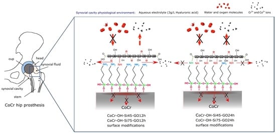
Barrier Graphene Oxide on a CoCr Alloy via Silane/GO Covalent Bonding and Its Electrochemical Behavior in a Simulated Synovial Fluid Electrolyte

by
Luna Sánchez-López
1,2,3,
Belén Chico
1,
María Lorenza Escudero
1,
Rose María Lozano
2,* and
María Cristina García-Alonso
1,*
1
Centro Nacional de Investigaciones Metalúrgicas (CENIM), Consejo Superior de Investigaciones Científicas (CSIC), Avenida Gregorio del Amo, 8, 28040 Madrid, Spain
2
Centro de Investigaciones Biológicas-Margarita Salas (CIB-MS), Consejo Superior de Investigaciones Científicas (CSIC), C/Ramiro de Maeztu, 28040 Madrid, Spain
3
Program in Advanced Materials and Nanotechnology, Doctoral School, Universidad Autónoma de Madrid (UAM), 28049 Madrid, Spain
*
Authors to whom correspondence should be addressed.
Metals 2023, 13(8), 1331; https://doi.org/10.3390/met13081331
Submission received: 9 June 2023 / Revised: 21 July 2023 / Accepted: 24 July 2023 / Published: 26 July 2023
(This article belongs to the Special Issue Corrosion and Surface Modification of Metallic Materials (Volume 2))

Abstract

:
In this work, impermeable and ultrathin surface nanomodifications for joint applications based on graphene oxide (GO) are assembled on CoCr surfaces via covalent immobilization between GO nanosheets and silane monolayers. Two silane curing temperatures, 45 °C for 24 h and 75 °C for 30 min, on CoCr surfaces and two incubation times for GO suspension, 12 h and 24 h, on silanized CoCr surfaces are prepared. Electrochemical characterization is performed using electrochemical impedance spectroscopy (EIS) in a 3 g/L hyaluronic acid solution. Results show that GO nanosheets immobilized with silane covalent bonding confer impermeability of sp2 networks on GO and strong interfacial adhesion of GO sheets anchored to silanized CoCr via organosilane chemistry, which prevents the permeation of oxidant species at the metal interface. At short GO incubation times (12 h), the Rs values decrease with the immersion time, indicating that small species, such as metal ions, are able to diffuse through the interlayer gaps of nanolayers. Longer GO incubation times (24 h) favor the formation of bonds between the GO and the silane, thus slowing downdiffusion and metal ion release into the medium. EIS data confirm the impermeability of GO nanocoatings with lengthening GO incubation time for medical application of metallic implants.

Graphical Abstract

1. Introduction

Cobalt chromium (CoCr) alloys are widely used as metal implants in hip and knee replacements, vascular stents, heart valves, and dental prostheses, mainly due to their shear and wear resistance [1,2]. In addition, the good corrosion resistance of CoCr depends on the formation of a highly adherent and stable protective passive film that forms on the CoCr surface [3], which reduces the corrosion and degradation of the implant [4].
However, concerns have arisen about the associated toxicity of CoCr alloys [5] because of the release of Co and Cr ions into physiological fluids and biological tissues [6,7], which are related to local and systemic toxicities, genotoxic and carcinogenic effects, immunological and inflammation responses, osteolysis, and other disorders [8,9,10,11,12]. In fact, Co and Cr blood levels are used for the identification and prediction of complications with prostheses [13,14,15,16,17]. Novel graphene-based surface modifications could mitigate the release of metal ions while preserving the required bulk mechanical properties of metal implants by applying the unique two-dimensional properties of graphene. The 0.064 nm pore size of sp2 hybridized carbon planes makes graphene, the world’s thinnest material, impermeable to all atoms and ions (except H+) in solid, liquid, or gas forms [18,19,20]. Due to its excellent ion-diffusion barrier properties, graphene has potential applications in ultra-high permeation barrier films [21,22], as well as anticorrosion applications [23,24,25,26] via the assembly of graphene monolayers in 2D nanocoatings or the assembly of graphene multilayers in thicker 3D coatings. However, when assembling nanocoatings of a graphene monolayer, the interfacial bond energy between graphene and the metal substrate is a key parameter determining whether pristine graphene can prevent diffusion across its basal plane [27]. When the metal/graphene interface is produced via chemisorption on strongly interacting metals Ni, Co, Ru, Pd, and Ti (with bond-formation energies of 0.09–0.4 eV), the anti-diffusion properties are preserved, as the chemisorbed graphene can prevent water permeation through its basal plane. On the other hand, in physisorbent metals Ag, Al, Cu, Cd, Ir, Pt, and Au, with very weak bond formation (0.03–0.05 eV), graphene can be easily decoupled, and oxidizing species can diffuse through the basal plane of graphene, permeating into the metal surface. Therefore, the long-term anticorrosion properties of graphene nanocoatings are only maintained on chemisorbed metals with strong interfacial bonds at the graphene–metal interface [28,29,30].
Similarly, a precursor of graphene, graphene oxide (GO), can be used to assemble impermeable [31] and anticorrosive coatings [32,33,34,35,36]. However, the assembly of a monolayer of GO is often hampered by the interaction of GO/metal interfaces via physisorption, which prevents proper permeation barrier properties at the metallic interface. In these cases, traditional 3D thick coatings are formed by vertically stacking multiple GO layers, where the degree of anticorrosion/impermeability of the coatings is based on (1) the lengths of the tortuous path of molecules diffusing through the interspaces between adjacent GO layers [37,38,39] and (2) GO-reduction methods to remove oxygenated groups, which decrease the interlayer separation and block the tortuous interlayer diffusion between the reduced GO layers [40,41].
Nevertheless, anticorrosive 2D nanocoatings of GO monolayers might be obtained via surface engineering by providing a strong interfacial contact between GO and the metal surface. It has been shown in the literature that it is possible to anchor GO monolayers to silica via direct Si–O covalent bonds, avoiding the intercalation of oxidizing species at the interface and oxidation of Si [42,43]. Recently, this strategy has been used with GO monolayers that were covalently immobilized on CoCr and described by the authors in [44]. For this purpose, the authors used 3-Aminopropyl-triethoxysilane (APTES) as a silane coupling agent that works as an intermediate for the covalent attachment of self-assembled silane monolayers (SAMs) on the oxide surface [45] of the CoCr alloy. Further, the covalent bonding of GO was carried out via reactive organoamine groups of APTES [46,47], thus promoting the chemical adsorption of GO sheets on the CoCr surface.
In this work, improvements in the interfacial strength via covalent bonding interaction between GO and the metal surface are characterized via EIS to assess the barrier performance of GO. The electrochemical behavior of the modified CoCr surfaces is characterized at each modification step during the two-dimensional assembly of GO nanocoatings on silanized CoCr surfaces. The electrochemical properties of the assembled GO nanocoatings on CoCr are analyzed in depth, contributing to the characterization of physicochemical properties of strongly interacting GO–metal interfaces.

2. Materials and Methods

2.1. Materials

Biomedical-grade CoCr alloy was supplied by International Edge with the following nominal chemical composition (wt.%): 27.25% Cr, 5.36% Mo, 0.69% Mn, 0.68% Si, 0.044% C, 0.02% W, 0.15% N, 0.002% Al, 0.001% S, 0.002% P, 0.002% B, 0.001% Ti, and balanced Co. CoCr surfaces were polished with SiC abrasive papers grit sizes from 600 to 2000 and then mirror-polished with 3 µm and 1 µm diamond paste and rinsed with distilled water. Bare polished CoCr surfaces are referred to as CoCr. 3-aminopropyl-triethoxysilane (APTES) agent was purchased from Merck, Sigma-Aldrich. The GO was supplied as an aqueous suspension of concentration 4 g/L by the GRAnPH of Grupo Antolin.

2.2. Preparation of Multilayer Systems

All multilayer surfaces were obtained as previously described [44]. Briefly, the CoCr surface was hydroxylated through alkalization in NaOH 5 M for 2 h to obtain the surface, named CoCr-OH. Subsequently, silanization was carried out using APTES. APTES was pre-mixed at 2% vol in isopropanol-water (200:1 v/v) and stirred for 1 h. After this, the hydroxylated CoCr surfaces were immersed in the APTES solution at room temperature for 1 min. The silane-coated samples were kept under curing conditions at 45 °C and 75 °C for 24 h and 30 min, respectively, resulting in covalently bonded silane monolayers, named CoCr-OH-Si45 and CoCr-OH-Si75, respectively. Finally, GO multilayer surfaces were assembled by immersing both CoCr-OH-Si45 and CoCr-OH-Si75 surfaces in 4 g/L GO suspensions at 60 °C for 12 h and 24 h to obtain surfaces named CoCr-OH-Si45-GO12h, CoCr-OH-Si75-GO12h and CoCr-OH-Si45-GO24h, and CoCr-OH-Si75-GO24h.

2.3. Electrochemical Characterization: Electrochemical Impedance Spectroscopy (EIS)

The electrochemical behavior of each layer deposited on CoCr surfaces was examined by electrochemical impedance spectroscopy (EIS) for 7 days in 3 g/L hyaluronic acid (HA) aqueous solution at the same concentration as the physiological content of HA in synovial fluid from healthy joints [48]. The measured conductivity of HA was 420 µS/cm. Impedance tests were performed in a three-electrode electrochemical cell with the modified CoCr surfaces acting as the working electrode, a Pt wire acting as counter electrode, and Ag/AgCl (3 M KCl) as a reference electrode. The testing area of the working electrode for all electrochemical tests was 0.39 cm2. An Autolab32 potentiostat/galvanostat was used to generate a sinusoidal wave of 10 mV amplitude in the frequency range 100 kHz to 1 mHz, logarithmically spaced by 5 points/decade, which was applied at the corrosion potential Ecorr. The electrochemical behavior was analyzed by fitting the experimental impedance data with equivalent electric circuits. Component values of the equivalent circuit were estimated by applying a non-linear least-squares (NLLS) program included in the Z-view software, as previously reported [49,50]. The fitting criteria used for equivalent circuits were the lowest chi-square value and the lowest absolute errors.
All the tests were performed in duplicate.

3. Results

The electrochemical behavior of the modified CoCr surfaces was analyzed from day 0 to day 7 of immersion in a simulated physiological synovial cavity medium (3 g/L HA electrolyte) by EIS. Experimental impedance data were fitted to the electric equivalent circuits (EEC) shown in Figure 1. EEC with one time constant, (a), was used for uncoated samples, while the circuit with two serial time constants, (b), was chosen as the best equivalent circuit fitting the experimental impedance data of coated surfaces.
The passive components of EECs were the solution resistance (RS), the oxide layer resistance (RL) in parallel with its constant phase element (CPE1), simulating the non-ideal impedance behavior associated with distributed time constants of the metal surfaces, and the coating resistance (RCOAT) in parallel with a constant phase element (CPE2) corresponding to thin 2D coatings.

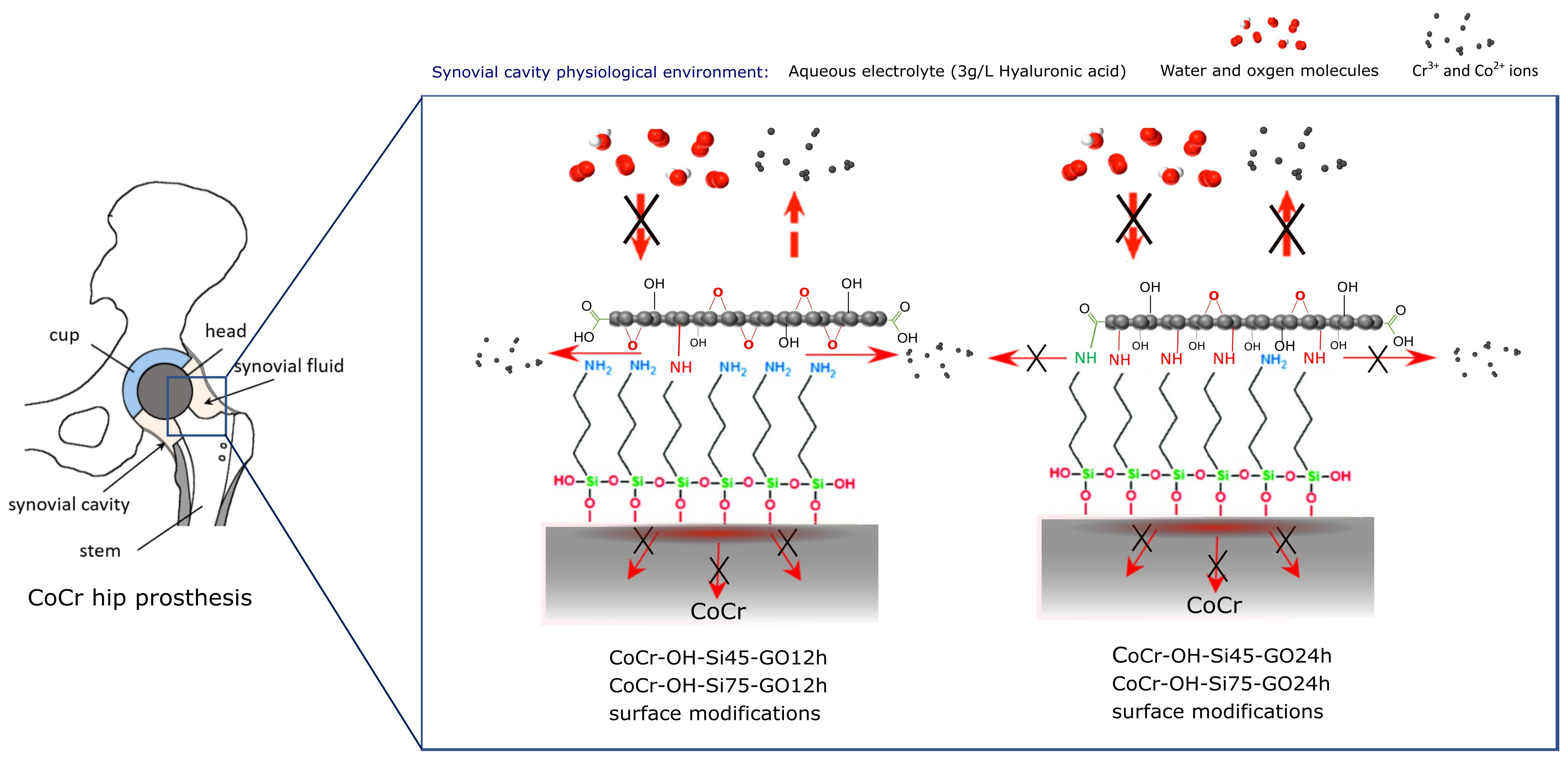
3.1. Bare CoCr and CoCr-OH

Figure 2 shows the Nyquist plots (a1 and b1) (imaginary impedance versus real impedance) and the Bode plots (impedance modulus, a2 and b2, and phase angle, a3 and b3 versus frequency) of the metal surfaces before alkaline treatment, CoCr (a), and after alkaline treatment, CoCr-OH (b). Table 1 shows the fitting results for each component of the equivalent circuit in Figure 1a (single time constant) for CoCr and CoCr-OH. The effective capacitance values (Ceff) were also estimated from CPE under the assumption of a system with a normal time-constant distribution through a surface layer, in agreement with [51].
The Nyquist plots of the CoCr surfaces over 7 days in hyaluronic acid aqueous solution of Figure 2(a1) show capacitive arcs whose amplitude increases over the immersion time. The amplitude of each arc is associated with the oxide layer resistance (RL, in the equivalent circuit of Figure 1a), whose values increase by one order of magnitude with increasing immersion time (Table 1).
The increase in RL with immersion time reveals that the resistance of the oxide layer, initially air-formed on the CoCr surface, increases with immersion time in the electrolyte and improves its corrosion behavior.
The Bode plots in Figure 2(a2) show, at the lowest frequency, a high impedance modulus and phase angle values around −70°, which approach −90° as the immersion time in the HA electrolyte increases. This high phase value at the lowest frequencies provides information on the insulating capacitive behavior of the oxide film. The CPE and Ceff values associated with quasi-capacitance values (n values close to 1 in Table 1) are lower than the associated characteristic value of the double layer, thus reflecting the contribution of the oxide film on the CoCr surface [52].
The improvement in the corrosion resistance of CoCr upon immersion in a simulated synovial fluid is consistent with an increase in the thickness of the oxide layer and with changes in the chemical composition of the previously formed passive layer in air. During the immersion of CoCr surfaces in aqueous solutions, it was observed that chromium enrichment occurs via the formation of Cr2O3 and Cr(OH)3 species [53] as a result of the dissolution of the Co present in the oxide film formed in air [54,55,56].
The electrolyte resistance, RS, decreased from day 0 to day 7 upon immersion, which could be associated with the release of metal ions from the oxide film into the hyaluronic acid solution. This result is consistent with evidence describing in vitro metal release from CoCr surfaces [56] and in vivo levels of Co and Cr in the synovial fluid and blood of patients with CoCr implants [17,57,58].
The Nyquist plots of the CoCr-OH surfaces over 7 days in hyaluronic acid aqueous solution in Figure 2(b1) show arcs whose amplitude increases over the immersion time, which results in higher RL values of one order of magnitude at the end of the test (Table 1). Nevertheless, it is remarkable that on just day 0 of immersion, the semicircle amplitude in the Nyquist plot (Figure 2(b1)) decreased with respect to the Nyquist arc of the CoCr samples on day 0 (Figure 2(a1)), indicating a lower resistance of the oxide layer. The fitting of the electrochemical response of the CoCr-OH surfaces (Table 1) shown in Figure 2b reveals that the resistance of the oxide layer, RL, formed on CoCr-OH was drastically reduced as a consequence of the applied alkalization treatment. The alkalization treatment was initially detrimental regarding the anticorrosive purposes, as it causes the loss of the air-passivated protective layer on the CoCr (a decrease in RL).
The lower resistance of the alkali-formed oxide layer is associated with a change in chemical composition, as alkaline NaOH treatments in CoCr lead to the predominant formation of Co oxides and inhibit the formation of chromium oxi-hydroxides in the oxide layer [44,59]. This effect is also observed in CoCr-OH surfaces that indicate improvement in the corrosion behavior, but the RL values are lower than those obtained in CoCr surfaces.
However, as the immersion time in the HA solution increases, the trend of the CoCr-OH electrochemical parameters evolves similarly to that of the CoCr parameters. After 7 days of immersion, RL approaches an oxide layer resistance value similar to the initial RL value of the oxide film of CoCr surfaces at day 0.
The Bode plots in Figure 2(b3) show that phase angles at low frequencies decrease with increasing immersion time in HA, reaching −60° at day 7 of immersion (Figure 2(b3)) and approaching phase angle levels of −90° as the oxide layer in CoCr in Figure 2(a3). At day 0 of immersion, the phase angle value of CoCr-OH shifted toward a more positive value of −20° at the lowest frequency, compared to phase angle values close to −90° in the CoCr samples. This reveals a difference in the electrochemical behavior of the oxide layer formed after the alkalization treatment compared to the passive layer formed in air. On the other hand, the effective capacitance values (Table 1) take capacitance values similar to those of CoCr surfaces. Altogether, the impedance data indicate the detrimental effect in the oxide layer resistance of alkali treatment and the restoration of the insulating properties on the hydroxylated surface over immersion time. This can be explained by the development of a chromium-enriched passive layer on the CoCr-OH surface upon contact with the electrolyte, similarly to the progression of the passive layer in CoCr surfaces.
The dissolution progress of Co ions from the oxide film on CoCr-OH surfaces can contribute to the observed fluctuation in the solution resistance, RS, toward lower RS values from day 0 to day 7 of immersion.

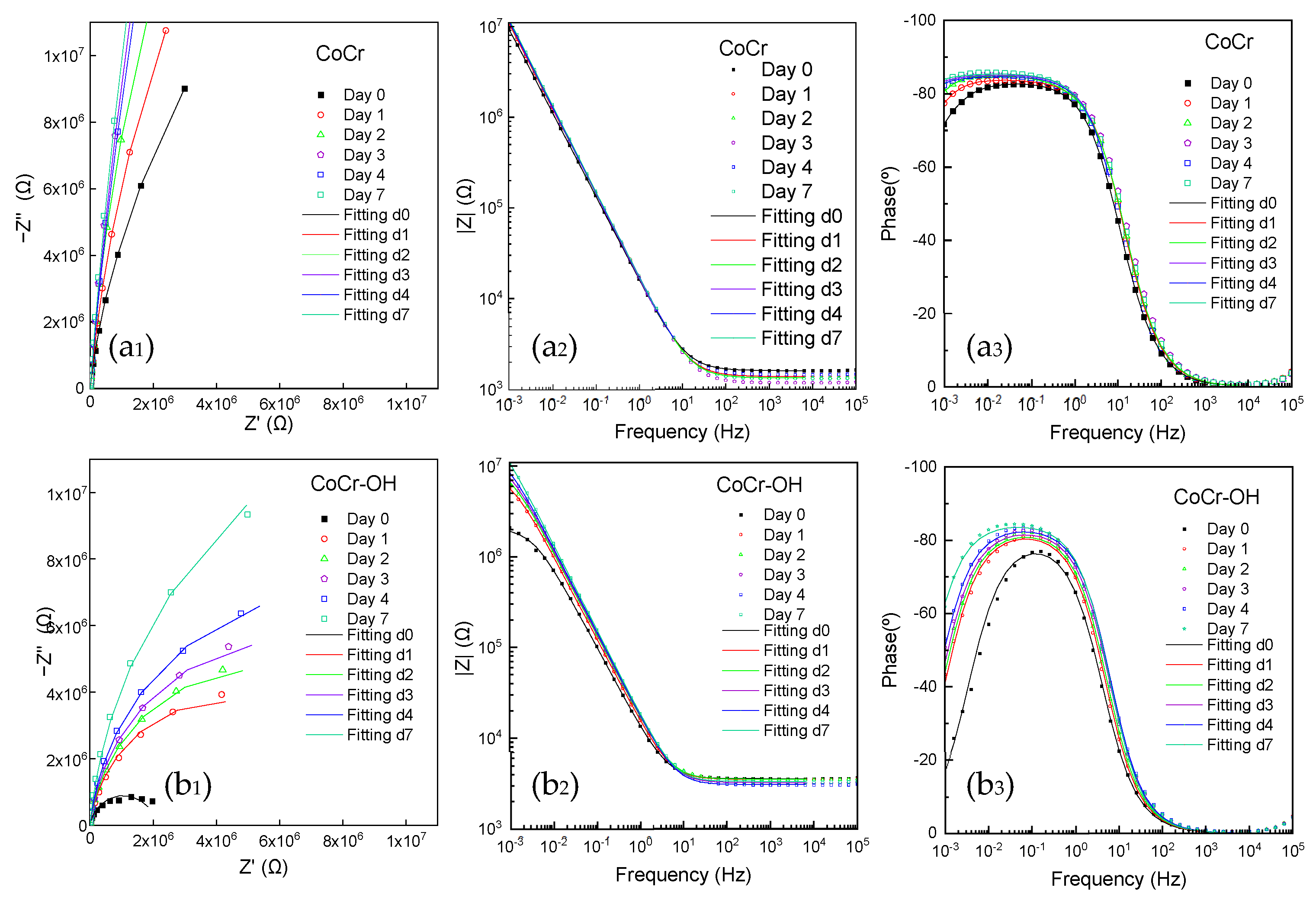
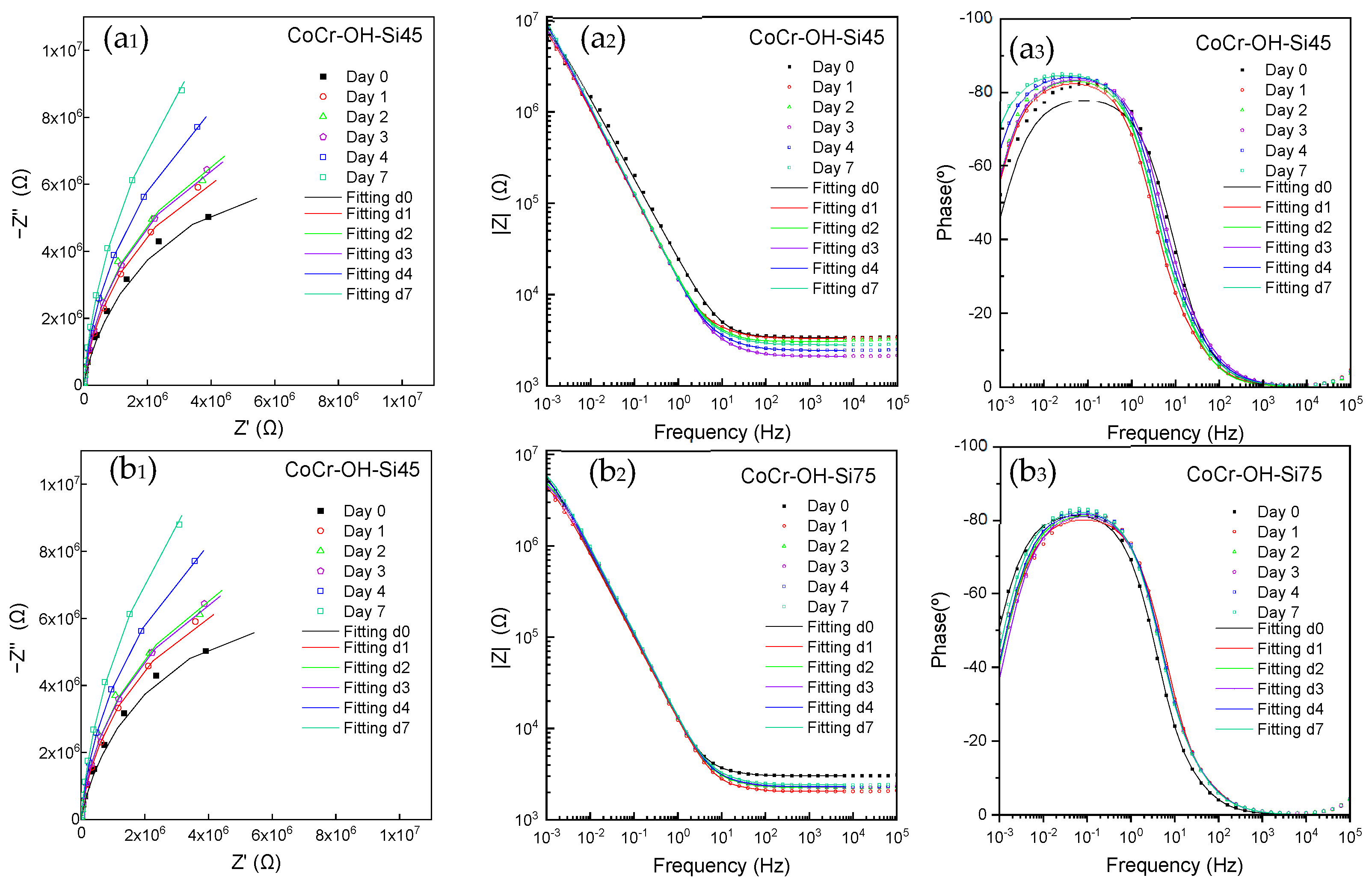
3.2. Silanized CoCr-OH Samples (CoCr-OH-Si)

Figure 3 shows the Nyquist and Bode diagrams after the silanization of the alkalized surface CoCr-OH-Si. Two silane-coated surfaces were obtained using the same silane agent (APTES) but with different curation conditions for the self-assembly of ultrathin silane monolayers (SAMs). The CoCr-OH-Si45 surfaces were obtained by applying a curing temperature of 45 °C and a curing time of 24 h, while the CoCr-OH-Si75 surface was obtained by applying a curing temperature of 75 °C for 30 min.
The most reasonable physical meaning is to take into account two time constants due to the response of the silane coating and the metal surface. Both time constants are very close and overlap, so they are difficult to distinguish. The EEC with two serial time constants (Figure 1b) was used to fit the thin APTES silane monolayers on CoCr-OH surfaces, except for the CoCr-OH-Si45 surface on day 0 of immersion and CoCr-OH-Si75 surfaces on days 0 and 1 of immersion, which were fitted with the EEC corresponding to a single time constant (Figure 1a). Table 2 shows the fitting results for each component of the equivalent circuit in Figure 1 for CoCr-OH-Si45 and CoCr-OH-Si75.
The impedance response of the CoCr-OH-Si surfaces shows a different trend in the first 24 h of immersion. The Nyquist plots of the CoCr-OH-Si-45 surfaces (Figure 3(a1)) show semicircle arcs whose diameter increases with immersion time. On the other hand, the CoCr-OH-Si75 surfaces showed a wide arc on the first day of immersion, and after 24 h, the diameter was reduced by half. After 24 h of immersion, the amplitude of the semicircles increased progressively with immersion time until the end of the test, following the same trend as CoCr-OH-Si45 surfaces.
The CoCr-OH-Si45 (at day 0 of immersion) and CoCr-OH-Si75 (at days 0 and 1 of immersion) surfaces could only be fitted considering one time constant, where the resistance and CPE values were associated with RCOAT and CPE2 due to the response of the silane coating. After 24 h of immersion of CoCr-OH-Si45 and after 48 h of immersion of CoCr-OH-Si75, electrolyte ingress into the coating/metal interface occurred, and the second time constant, associated with the metal surface, appeared.
The EEC with two time constants in series (Figure 1b) fits with the thin nature of APTES silane monolayers on CoCr-OH surfaces with RCOAT values in the range of 100–1000 Ω (Table 2). A better anticorrosive silane coating was obtained in CoCr-OH-Si45 (RCOAT values ≈ 700 Ω, after 24 h) with respect to CoCr-OH-Si75 (RCOAT values ≈ 200 Ω, after 48 h). The different evolution of the electrochemical parameters in the coated surfaces can be directly associated with the different chemical structures formed in the curing conditions of the silane films. This can be directly related to condensation reactions between Si−OH groups forming Si−O−Si bonds, which occurred over a longer curing time in CoCr-OH-Si45, forming a highly dense, crosslinked, and hydrophobic siloxane network [60]. The hydrolytic stability and crosslinking of silane SAMs are of great concern for the coating of metals [45,61,62], and it has been observed that Si−O−Si bonds provide hydrolytic stability to the silane layer while metal−O−Si bonds provide poor hydrolytic stability [61].
The CoCr-OH-Si75 surfaces suffer an ingress of electrolytes through the network of the silane coating, with a low degree of crosslinking, which forms a more permeable silane layer. Non-condensed silanol groups also form a more hydrophilic silane polymeric network, allowing a high degree of water absorption.
The highest RCOAT values in CoCr-OH-Si-45 surfaces are accompanied by higher RL values (Table 2), denoting a better corrosion behavior of CoCr-OH-Si samples cured at 45 °C for 24 h.
Finally, the Bode plots of the phase angle versus frequency in the CoCr-OH-Si75 surfaces show more positive phase angles at low frequencies (−50° or −40°) compared to the initial phase angle (−55°) on the first day of immersion. This is in contrast to CoCr-OH-Si45, which revealed a better insulating evolution with more negative phase differences at low frequencies (−60°) throughout the immersion tests.
In conclusion, the electrochemical analysis performed through the comparative impedance data on silane SAMs allows us to distinguish between the two applied silanization treatments, in which the denser and crosslinked siloxane layer formed on CoCr-OH-Si45 provides higher protection against corrosion in the HA solution.

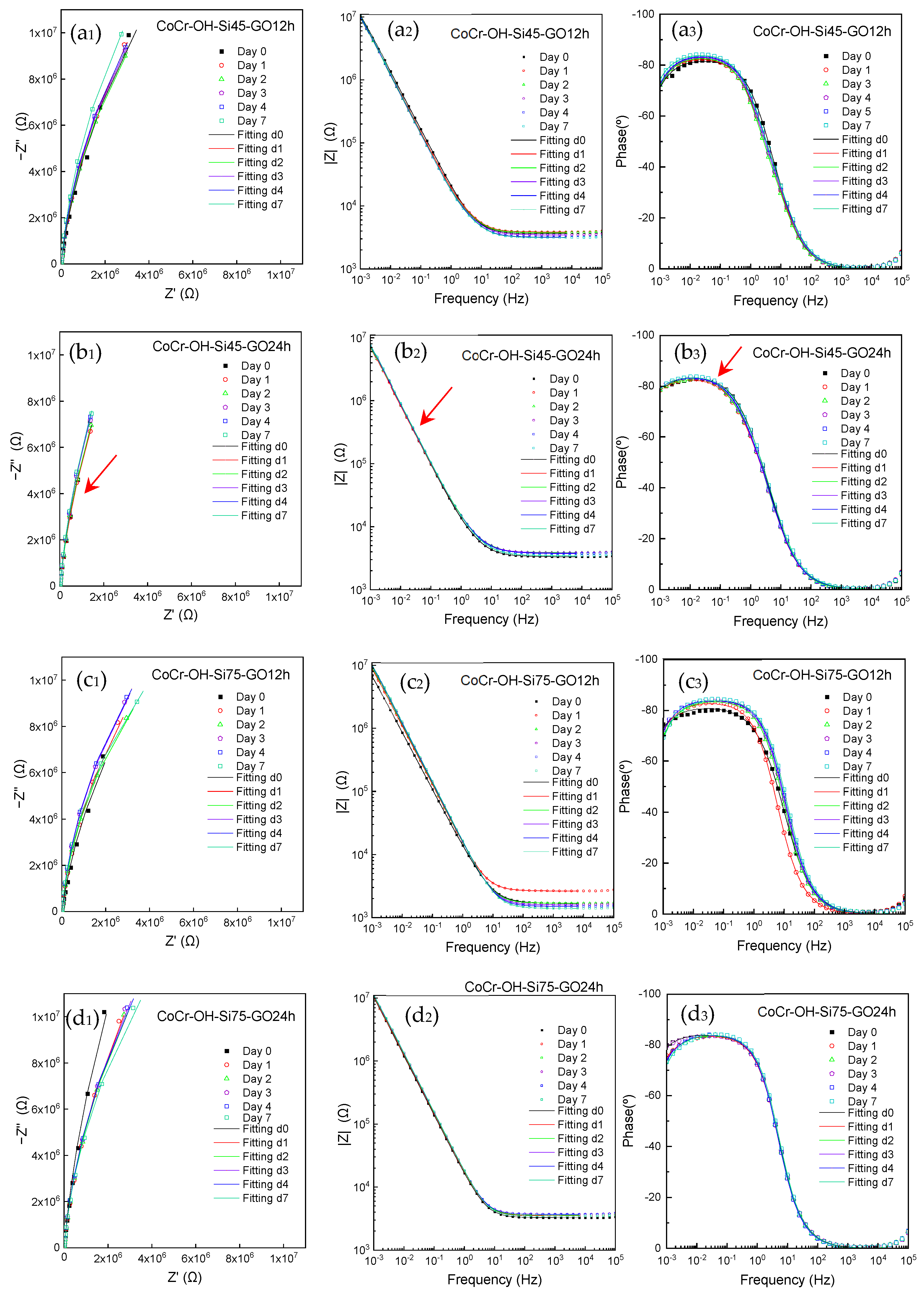
3.3. Graphene Oxide on Silanized CoCr-OH Samples (CoCr-OH-Si-GO)

Figure 4 shows the Nyquist and Bode plots of GO-based ultrathin nanocoatings on CoCr-OH-Si samples over 7 days of immersion in HA solution. The self-assembly of GO nanosheets on silane-coated CoCr-OH surfaces was obtained by incubating CoCr-OH-Si45 and CoCr-OH-Si75 with GO suspensions for 12 h or 24 h. GO–silane multilayer systems were obtained under four different conditions, namely, CoCr-OH-Si45-GO12h, CoCr-OH-Si45-GO24h, CoCr-OH-Si75-GO12h, and CoCr-OH-Si75-GO24h (Figure 4a–d).
The thin 2D assemblies of GO nanosheets on the silanized CoCr surfaces also show proper fitting with EEC with two time constants in series (Figure 1b). RCOAT comprises layered GO/silane coating. The fitting values for each EEC element are shown in Table 3.
The impedance data of Figure 4 show that, upon deposition of GO on silanized CoCr, the corrosion behavior is largely stabilized on these surfaces. All the impedance results reveal the same diagrams independently of the immersion time, revealing a high stability, with minor differences. The barrier properties provided by the GO/silane coating also correlate with the steadiness of capacitive Nyquist arcs of unchanged amplitudes through immersion (Figure 4(a1,b1,c1,d1)) and stabilized Bode phases (Figure 4(a3,b3,c3,d3)). This stabilization is associated with the barrier effect provided by the GO anchorage in the silane layer, leading to the formation of protective and ultrathin GO-based modifications on CoCr, which can be explained by two features of these nanocoatings: firstly, the sp2 hybridized carbon networks of the adsorbed GO nanosheets, which work as an effective physical barrier preventing the diffusion of molecules through sp2 planes, and secondly, the strong interfacial adhesion of the chemisorbed GO nanosheets on the silanized surfaces, impeding the desorption of the anchored GO and the intercalation of molecules from the aqueous medium at the metal interface, such as water and oxygen, which limits the progress of the passivation of the metal substrate upon immersion in the HA solution.
Nevertheless, some differences can be observed from the fitted RCOAT values (Table 3) for each condition. An increase in RCOAT is induced on CoCr-OH-Si45-GO12h and CoCr-Si45-GO24h in comparison with CoCr-OH-Si45, as can be seen from the comparison of Table 2 and Table 3. More importantly, RCOAT remains almost constant from day 1 of immersion in CoCr-OH-Si45-GO12h (RCOAT ≈ 2500 Ω) and CoCr-Si45-GO24h (RCOAT ≈ 5000 Ω) throughout the immersion time (Table 3), being the highest stabilized RCOAT values obtained for CoCr-OH-Si45-GO24h surfaces. The CPE2 associated with the Si-GO coating reveals n values close to 0.5, indicating that diffusion becomes important in the corrosion process of the system.
The Bode plots of the phase angle versus frequency (Figure 4(a3,b3,c3,d3)) show an interesting fact in the variation in phase angle at the lowest frequencies. In the decade of low frequencies (10−2–10−3 Hz), a decrease in the θ values is observed on surfaces CoCr-OH-Si45-GO12h, CoCr-Si75-GO12h, and CoCr-Si75-GO24h. In CoCr-OH-Si45-GO24h, this decrease is not observed (Figure 4(b3)) suggesting an improvement in the insulating properties of this surface modification with the longer GO incubation time.
In addition, the CoCr-OH-Si45-GO24h surface seems to provide the most stationary electrochemical response of the four GO–silane multilayer systems studied. Together with enhanced electrochemical stability of Nyquist and Bode plots (Figure 4(b1,b2,b3)), the fitted values for EEC elements (Table 3) followed the same trend, where RS, RCOAT, CPE2, n2, RL, CPE1, and n1 were stabilized to the greatest extent in CoCr-OH-Si45-GO24h compared to the rest of the GO-based multilayer systems, which showed larger oscillations in their values throughout the immersion period from day 0 to day 7.

4. Discussion

The mechanisms involved in blocking the interlayer diffusion in GO–silane assembled nanofilms are proposed herein. The strong interfacial adhesion of the chemisorbed GO on the four surfaces of the silane/GO multilayer system permitted the assembly of interlayer spaces small enough to slow down the inward diffusion of large electrolyte molecules, such as water, as the high RCOAT reveals, overall, in CoCr-OH-Si45-GO24h. This is the reason for the high stability of the impedance data over the immersion time.
The oxygen-containing groups of GO nanolayers are removed during the covalent immobilization of GO through two mechanisms: nucleophilic substitution reactions, which take place between the GO basal plane epoxy groups and APTES primary amines, and through additional reaction pathways, via the removal of -OH from the GO carboxyl groups upon reaction with APTES primary amines [44]. The two-dimensional physical-barrier properties of GO were maximized in the horizontal plane of the CoCr surface through the attachment of epoxy groups located in the GO basal plane through nucleophilic reaction with the primary amines located on top of silane SAMs. Additional silane/GO bonding at the GO edges further contributed to the covalent immobilization of GO on CoCr [44].
The oxygen-containing groups of GO are known to act as interlayer spacers [63,64,65], and their reduction leads to a controlled decrease in the size of the interspacing channels in stacked GO layers [66]. In GO-based nanocoatings with the largest extent of GO/silane covalent bonding, the release of metallic ions into the electrolyte medium can be minimized by separation mechanisms (size exclusion and/or electrostatic repulsion), which control mass transport through GO membranes [66,67].
The reduced interlayer distances resulting from these assemblies of GO with silane can obstruct the diffusion of metal ions via size exclusion when the interlayer channels reach a size smaller than that of the hydrated metal ions. Reduced interlayer distances in GO membranes are applied for precise molecular sieving of salts and mono/multi-valent metal ions [68,69,70,71,72]. In particular, interlayer distances smaller than 8 Å provide accurate sieving of multi-valent metal ions through a steric effect [72]. Although hydrated ion diameters can be rejected due to the size-exclusion effect, partial ion dehydration permits the permeation of dehydrated ions in GO interlayer nanochannels with similar d-spacing dimensions [73]. However, divalent and trivalent ions such as Cr3+ and Co2+ exhibit strongly interacting water shells due to their high ionic charge, which limits their dehydrated permeation through GO membranes with d-spacing <10 Å, in contrast to the permeation of dehydrated monovalent ions with lower dehydration energy barriers [71,73,74]. Thus, the dehydrated permeation of Cr3+ and Co2+ through these interspace nanofilms is limited by the high dehydration energy barriers of these ions.
Apart from size-sieving effects, the modification of the charges of GO nanosheets can also contribute to the rejection of metal ions in these nanocoatings. Initially, GO nanosheets are negatively charged by oxygen-containing groups, which allow for the interspatial diffusion of oppositely charged Cr and Co cations. After functionalizing the GO nanosheets with APTES amino-terminal groups during covalent immobilization, the positively charged GO nanosheets can reject Cr3+ and Co2+ interlayer diffusion through the Donnan exclusion effect. Through this mechanism, the charged film tends to reject cations by electrostatic repulsions [68]. This effect is exploited in positively charged GO membranes that reject the permeation of divalent cations [75] and in negatively charged GO sheets that impede the permeation of negatively charged organic dyes [76].
The larger abundance of GO covalent bonds on the CoCr-OH-Si45-GO24h surface provided the strongest GO–metal interaction. This enhanced adhesion strength of GO in this GO/silane multilayer system optimized the shielding of oxidizing molecules toward the metallic interface (Figure 4b). The CoCr-OH-Si45-GO24h surfaces seem to effectively shield the CoCr surface from the surrounding hyaluronic acid solution over 7 days of immersion. The physicochemical changes in GO/silane interspaces that occur in CoCr-OH-Si45-GO24h through covalent reactions at the GO/silane interface can alter the permeability of the GO-based nanofilms by (1) reducing the height dimensions of the interlayer nanochannels during the removal of oxygen-containing GO groups, exerting a size-exclusion effect on the diffusion of hydrated and dehydrated Cr3+ and Co2+ ions, and (2) modifying the basal planes of GO with positive amine charges, which can exert an electrostatic repulsion effect on the diffusion of metal cations. The previous characterization of the surface chemistry of the ultrathin/nanolayered surface modifications, performed using X-ray photoelectron spectroscopy (XPS) [44], permitted the analysis of the covalent anchoring mechanisms of the GO nanosheets to the metal substrate in the condition of the CoCr-OH-Si45-GO24h multilayer system, through the previously described mechanisms that could reduce the interlayer spatial distance, d, in these assembled GO-based nanocoatings.
The retention of GO impermeability properties appears to be directly associated with the longer incubation time of the GO suspensions on the CoCr-OH-Si surfaces. At longer incubation times, more nucleophilic reactions can take place in the free and suspended GO nanosheets, promoting a higher conversion of primary to secondary amines on the silanized surfaces [44]. In this way, a higher efficiency of GO/silane covalent bond formation is achieved through the chemical route of nucleophilic substitution, generating a strong interfacial adhesion between the GO and the metal substrate. Small enough interlayer space distances can exclude diffusion of metal cations by size. In GO-based nanocoatings, this interlayer distance can be reduced in a large proportion of covalent reactions between the self-assembled GO nanosheets and the silane layer. Electrostatic repulsion between chemically modified GO with APTES positively charged amines can also repel the diffusion of metal cations. However, the outward diffusion of smaller components, mainly Co2+ and Cr3+, with hydrated diameters of 0.6 nm and 0.9 nm, respectively [77], could be possible through the interlayer channels in the basal plane of GO immobilized on silane, especially for shorter incubation times (CoCr-OH-Si45-GO12h and CoCr-OH-Si75-GO12h).
The evaluation of how the electrolyte resistance progresses over the immersion time for each surface modification also reveals additional information about the multilayer network structure formed through the covalent bonding of GO to the metal substrates. The electrolyte resistance values, RS, for the CoCr-OH-Si samples incubated for longer immersion times (24 h) in the graphene oxide solution (CoCr-OH-Si45-GO24h and CoCr-OH-Si75-GO24h) remained almost constant from day 0 to day 7, which could be related to the minimal lixiviation of metal ions in the hyaluronic acid solution.
The sealing effect of this ultrathin and high-adherent surface modification could be applied on CoCr implants used for biomedical applications, such as joint and dental prostheses, vascular stents, and components of heart valves, by mitigating the leakage of metal ions in physiological fluids. These results are consistent with the decreased toxicities of graphene-encapsulated Ti and Cu implants, in which graphene nanocoatings prevent the leaching of metal ions from the implant surfaces [78,79,80]. In contrast to graphene-based encapsulation strategies, this encapsulation methodology is easily scalable to industrial applications through the self-assembly of inexpensive GO foils, compared to the chemical vapor deposition of graphene monolayers, where the barrier properties lie in tailoring a strong interfacial GO–metal adhesion.

5. Conclusions

The electrochemical impedance spectroscopy has proven to be extremely sensitive in the analysis of the barrier properties of GO-based nanocoatings that are chemically anchored to CoCr via organosilane interlayer chemistry.
The GO nanocoating with the strongest GO–metal interaction was obtained in CoCr-OH-Si45-GO24h by applying long reaction times between the self-assembled GO/silane layers, allowing the formation of a higher number of interfacial covalent bonds. Among the obtained nanocoatings, this system provides the most stabilized electrochemical surface response with the highest RCOAT when immersed for 7 days in the oxidizing electrolyte, isolating the metal surface and minimizing CoCr corrosion.
The immobilization by covalent bonding of GO to the silane interlayer is an effective method to obtain an ultra-barrier surface nanomodification on CoCr.

Author Contributions

L.S.-L.: Investigation, Validation, Writing—Original Draft, visualization; B.C.: Conceptualization, Methodology, Writing—Review and Editing; M.L.E.: Conceptualization, Writing—Review and Editing, Funding acquisition; R.M.L.: Conceptualization, Writing—Review and Editing, Funding acquisition; M.C.G.-A.: Conceptualization, Writing—Review and Editing, Supervision, Project administration, Funding acquisition. All authors have read and agreed to the published version of the manuscript.

Funding

Grant RTI2018-101506-B-C31 and RTI2018-101506-B-C33 were funded by Ministerio de Ciencia e Innovación, MCIN/AEI/10.13039/501100011033/, and “ERDF A way of making Europe”. Grant PRE2019-090122 was funded by Ministerio de Ciencia e Innovación, MCIN/AEI/10.13039/501100011033/and “ESF Investing in your future”.

Data Availability Statement

Data have not yet been shared due to privacy restrictions. In the future, the data will be deposited in the institutional repository of CSIC (Digital CSIC, https://digital.csic.es (accessed on 30 November 2023)).

Conflicts of Interest

The authors declare no conflict of interest.

References

  1. Milošev, I. CoCrMo Alloy for Biomedical Applications. In Biomedical Applications. Modern Aspects of Electrochemistry; Djokić, S., Ed.; Springer: Boston, MA, USA, 2012; Volume 55, pp. 1–72. [Google Scholar] [CrossRef]
  2. Taghizadeh, B.; Ghavami, L.; Derakhshankhah, H.; Zangene, E.; Razmi, M.; Jaymand, M.; Zarrintaj, P.; Zarghami, N.; Jaafari, M.R.; Shahri, M.M.; et al. Biomaterials in Valvular Heart Diseases. Front. Bioeng. Biotechnol. 2020, 8, 529244. [Google Scholar] [CrossRef]
  3. Milošev, I.; Strehblow, H.-H. The composition of the surface passive film formed on CoCrMo alloy in simulated physiological solution. Electrochim. Acta 2003, 48, 2767–2774. [Google Scholar] [CrossRef]
  4. Arnholt, C.M.; MacDonald, D.W.; Malkani, A.L.; Klein, G.R.; Rimnac, C.M.; Kurtz, S.M.; Kocagoz, S.B.; Gilbert, J.L. Corrosion Damage and Wear Mechanisms in Long-Term Retrieved CoCr Femoral Components for Total Knee Arthroplasty. J. Arthroplast. 2016, 31, 2900–2906. [Google Scholar] [CrossRef] [PubMed] [Green Version]
  5. Eichenbaum, G.; Wilsey, J.T.; Fessel, G.; Qiu, Q.-Q.; Perkins, L.; Hasgall, P.; Monnot, A.; More, S.L.; Egnot, N.; Sague, J.; et al. An integrated benefit-risk assessment of cobalt-containing alloys used in medical devices: Implications for regulatory requirements in the European Union. Regul. Toxicol. Pharmacol. 2021, 125, 105004. [Google Scholar] [CrossRef]
  6. Halwani, D.O.; Anderson, P.G.; Lemons, J.E.; Jordan, W.D.; Anayiotos, A.S.; Brott, B.C. In-vivo corrosion and local release of metallic ions from vascular stents into surrounding tissue. J. Invasive Cardiol. 2010, 22, 528. [Google Scholar] [PubMed]
  7. Matusiewicz, H. Potential release of in vivo trace metals from metallic medical implants in the human body: From ions to nanoparticles—A systematic analytical review. Acta Biomater. 2014, 10, 2379–2403. [Google Scholar] [CrossRef] [PubMed]
  8. Scharf, B.; Clement, C.C.; Zolla, V.; Perino, G.; Yan, B.; Elci, S.G.; Purdue, E.; Goldring, S.; Macaluso, F.; Cobelli, N.; et al. Molecular analysis of chromium and cobalt-related toxicity. Sci. Rep. 2015, 4, 5729. [Google Scholar] [CrossRef] [PubMed] [Green Version]
  9. Posada, O.M.; Gilmour, D.; Tate, R.J.; Grant, M.H. CoCr wear particles generated from CoCr alloy metal-on-metal hip replacements, and cobalt ions stimulate apoptosis and expression of general toxicology-related genes in monocyte-like U937 cells. Toxicol. Appl. Pharmacol. 2014, 281, 125–135. [Google Scholar] [CrossRef]
  10. Beyersmann, D.; Hartwig, A. Carcinogenic metal compounds: Recent insight into molecular and cellular mechanisms. Arch. Toxicol. 2008, 82, 493–512. [Google Scholar] [CrossRef]
  11. Bijukumar, D.R.; Segu, A.; de Souza, J.C.M.; Li, X.; Barba, M.; Mercuri, L.G.; Jacobs, J.J.; Mathew, M.T. Systemic and local toxicity of metal debris released from hip prostheses: A review of experimental approaches. Nanomed. Nanotechnol. Biol. Med. 2018, 14, 951–963. [Google Scholar] [CrossRef]
  12. Eltit, F.; Noble, J.; Sharma, M.; Benam, N.; Haegert, A.; Bell, R.H.; Simon, F.; Duncan, C.P.; Garbuz, D.S.; Greidanus, N.V.; et al. Cobalt ions induce metabolic stress in synovial fibroblasts and secretion of cytokines/chemokines that may be diagnostic markers for adverse local tissue reactions to hip implants. Acta Biomater. 2021, 131, 581–594. [Google Scholar] [CrossRef]
  13. Kwon, Y.-M.; Tsai, T.-Y.; Leone, W.A.; Liow, M.H.L. Sensitivity and Specificity of Metal Ion Levels in Predicting “Pseudotumors” due to Taper Corrosion in Patients with Dual Taper Modular Total Hip Arthroplasty. J. Arthroplast. 2017, 32, 996–1000. [Google Scholar] [CrossRef] [PubMed]
  14. Matharu, G.S.; Berryman, F.; Judge, A.; Reito, A.; McConnell, J.; Lainiala, O.; Young, S.; Eskelinen, A.; Pandit, H.G.; Murray, D.W. Blood Metal Ion Thresholds to Identify Patients with Metal-on-Metal Hip Implants at Risk of Adverse Reactions to Metal Debris: An External Multicenter Validation Study of Birmingham Hip Resurfacing and Corail-Pinnacle Implants. J. Bone Jt. Surg. 2017, 99, 1532–1539. [Google Scholar] [CrossRef] [Green Version]
  15. van der Weegen, W.; Sijbesma, T.; Hoekstra, H.J.; Brakel, K.; Pilot, P.; Nelissen, R.G. Treatment of Pseudotumors after Metal-on-Metal Hip Resurfacing Based on Magnetic Resonance Imaging, Metal Ion Levels and Symptoms. J. Arthroplast. 2014, 29, 416–421. [Google Scholar] [CrossRef] [PubMed]
  16. Sabah, S.A.; Bandi, A.S.; Maggiore, P.; Tarassoli, P.; Sampson, B.; Skinner, J.A.; Markel, D.C.; Bou-Akl, T.; Rossi, M.D.; Pizzimenti, N.; et al. Sensitivity and specificity of blood cobalt and chromium metal ions for predicting failure of metal-on-metal hip replacement. J. Bone Jt. Surg. Br 2011, 93-B, 1308–1313. [Google Scholar] [CrossRef] [Green Version]
  17. De Smet, K.; De Haan, R.; Calistri, A.; Campbell, P.; Ebramzadeh, E.; Pattyn, C.; Gill, H. Metal Ion Measurement as a Diagnostic Tool to Identify Problems with Metal-on-Metal Hip Resurfacing. J. Bone Jt. Surg. 2008, 90, 202–208. [Google Scholar] [CrossRef] [Green Version]
  18. Berry, V. Impermeability of graphene and its applications. Carbon 2013, 62, 1–10. [Google Scholar] [CrossRef]
  19. Bunch, J.S.; Verbridge, S.S.; Alden, J.S.; Van Der Zande, A.M.; Parpia, J.M.; Craighead, H.G.; McEuen, P.L. Impermeable Atomic Membranes from Graphene Sheets. Nano Lett. 2008, 8, 2458–2462. [Google Scholar] [CrossRef] [Green Version]
  20. Leenaerts, O.; Partoens, B.; Peeters, F.M. Graphene: A perfect nanoballoon. Appl. Phys. Lett. 2008, 93, 193107. [Google Scholar] [CrossRef] [Green Version]
  21. Sagade, A.A.; Aria, A.I.; Edge, S.; Melgari, P.; Gieseking, B.; Bayer, B.C.; Meyer, J.C.; Bird, D.; Brewer, P.; Hofmann, S. Graphene-based nanolaminates as ultra-high permeation barriers. npj 2D Mater. Appl. 2017, 1, 35. [Google Scholar] [CrossRef] [Green Version]
  22. Seo, H.-K.; Park, M.-H.; Kim, Y.-H.; Kwon, S.-J.; Jeong, S.-H.; Lee, T.-W. Laminated Graphene Films for Flexible Transparent Thin Film Encapsulation. ACS Appl. Mater. Interfaces 2016, 8, 14725–14731. [Google Scholar] [CrossRef] [PubMed]
  23. Topsakal, M.; Sahin, H.; Ciraci, S. Graphene coatings: An efficient protection from oxidation. Phys. Rev. B 2012, 85, 155445. [Google Scholar] [CrossRef] [Green Version]
  24. Ding, R.; Li, W.; Wang, X.; Gui, T.; Li, B.; Han, P.; Tian, H.; Liu, A.; Wang, X.; Liu, X.; et al. A brief review of corrosion protective films and coatings based on graphene and graphene oxide. J. Alloys Compd. 2018, 764, 1039–1055. [Google Scholar] [CrossRef]
  25. Malhotra, R.; Han, Y.; Nijhuis, C.A.; Silikas, N.; Neto, A.C.; Rosa, V. Graphene nanocoating provides superb long-lasting corrosion protection to titanium alloy. Dent. Mater. 2021, 37, 1553–1560. [Google Scholar] [CrossRef]
  26. Amin, I.; Batyrev, E.; de Vooys, A.; van der Weijde, H.; Shiju, N.R. Covalent polymer functionalization of graphene/graphene oxide and its application as anticorrosion materials. 2D Mater. 2022, 9, 032002. [Google Scholar] [CrossRef]
  27. Yang, M.; Liu, Y.; Fan, T.; Zhang, D. Metal-graphene interfaces in epitaxial and bulk systems: A review. Prog. Mater. Sci. 2020, 110, 100652. [Google Scholar] [CrossRef]
  28. Kozlov, S.M.; Viñes, F.; Görling, A. Bonding Mechanisms of Graphene on Metal Surfaces. J. Phys. Chem. C 2012, 116, 7360–7366. [Google Scholar] [CrossRef]
  29. Weatherup, R.S.; D’arsié, L.; Cabrero-Vilatela, A.; Caneva, S.; Blume, R.; Robertson, J.; Schloegl, R.; Hofmann, S. Long-Term Passivation of Strongly Interacting Metals with Single-Layer Graphene. J. Am. Chem. Soc. 2015, 137, 14358–14366. [Google Scholar] [CrossRef] [Green Version]
  30. Morrow, W.K.; Pearton, S.J.; Ren, F. Review of Graphene as a Solid State Diffusion Barrier. Small 2016, 12, 120–134. [Google Scholar] [CrossRef]
  31. Yin, C.; Du, X.; Ding, Z.; Zeng, Q.; Li, X.; He, C.; Xiong, B.; Li, J.; Zhou, Y. Gas permeation and microstructure of reduced graphene oxide/polyethyleneimine multilayer films created via recast and layer-by-layer deposition processes. RSC Adv. 2022, 12, 6561–6572. [Google Scholar] [CrossRef]
  32. Khosravi, I.; Shahryari, Z.; Moghadas, S.M.J.; Sarraf, H.T.; Yeganeh, M. Chapter 8—The application of graphene oxide as corrosion barrier. In Corrosion Protection at the Nanoscale; Rajendran, S., Nguyen, T.A., Kakooei, S., Yeganeh, M., Li, Y., Eds.; Micro and Nano Technologies; Elsevier: Amsterdam, The Netherlands, 2020; pp. 127–140. [Google Scholar] [CrossRef]
  33. Chae, W.H.; Sannicolo, T.; Grossman, J.C. Double-Sided Graphene Oxide Encapsulated Silver Nanowire Transparent Electrode with Improved Chemical and Electrical Stability. ACS Appl. Mater. Interfaces 2020, 12, 17909–17920. [Google Scholar] [CrossRef] [PubMed] [Green Version]
  34. Ruben, B.; Zhang, G.; Xin, T.; Giorgio, S.; Victor, M.; Gloria, G.; Michele, F.; Filippo, P.; Shuhui, S.; Nadhira, L.; et al. Graphene oxide/reduced graphene oxide films as protective barriers on lead against differential aeration corrosion induced by water drops. Nanoscale Adv. 2020, 2, 5412–5420. [Google Scholar] [CrossRef] [PubMed]
  35. Zhao, J.; Xie, X.; Zhang, C. Effect of the graphene oxide additive on the corrosion resistance of the plasma electrolytic oxidation coating of the AZ31 magnesium alloy. Corros. Sci. 2017, 114, 146–155. [Google Scholar] [CrossRef]
  36. Ramezanzadeh, B.; Ghasemi, E.; Mahdavian, M.; Changizi, E.; Moghadam, M.M. Covalently-grafted graphene oxide nanosheets to improve barrier and corrosion protection properties of polyurethane coatings. Carbon 2015, 93, 555–573. [Google Scholar] [CrossRef]
  37. Hu, Y.; Li, S.; Kang, W.; Lin, H.; Hu, Y. Surface modification of Ti6Al4V alloy by polydopamine grafted GO/ZnO nanocomposite coating. Surf. Coat. Technol. 2021, 422, 127534. [Google Scholar] [CrossRef]
  38. Lee, W.-J.; Kim, C.-S.; Yang, S.-Y.; Lee, D.; Kim, Y.-S. Ultrathin Super-barrier film via 100 % surface coating coverage of Self-assembled graphene oxide sheets. Chem. Eng. J. 2022, 440, 135913. [Google Scholar] [CrossRef]
  39. Srimaneepong, V.; Rokaya, D.; Thunyakitpisal, P.; Qin, J.; Saengkiettiyut, K. Corrosion Resistance of Graphene oxide/Silver Coatings on Ni–Ti alloy and Expression of IL-6 and IL-8 in Human Oral Fibroblasts. Sci. Rep. 2020, 10, 3247. [Google Scholar] [CrossRef] [Green Version]
  40. Su, Y.; Kravets, V.G.; Wong, S.L.; Waters, J.; Geim, A.K.; Nair, R.R. Impermeable barrier films and protective coatings based on reduced graphene oxide. Nat. Commun. 2014, 5, 4843. [Google Scholar] [CrossRef] [Green Version]
  41. Yamaguchi, H.; Granstrom, J.; Nie, W.; Sojoudi, H.; Fujita, T.; Voiry, D.; Chen, M.; Gupta, G.; Mohite, A.D.; Graham, S.; et al. Reduced Graphene Oxide Thin Films as Ultrabarriers for Organic Electronics. Adv. Energy Mater. 2014, 4, 1300986. [Google Scholar] [CrossRef] [Green Version]
  42. Rahpeima, S.; Dief, E.M.; Peiris, C.R.; Ferrie, S.; Duan, A.; Ciampi, S.; Raston, C.L.; Darwish, N. Reduced graphene oxide–silicon interface involving direct Si–O bonding as a conductive and mechanical stable ohmic contact. Chem. Commun. 2020, 56, 6209–6212. [Google Scholar] [CrossRef]
  43. Rahpeima, S.; Dief, E.M.; Ciampi, S.; Raston, C.L.; Darwish, N. Impermeable Graphene Oxide Protects Silicon from Oxidation. ACS Appl. Mater. Interfaces 2021, 13, 38799–38807. [Google Scholar] [CrossRef]
  44. Sánchez-López, L.; Chico, B.; Llorente, I.; Escudero, M.L.; Lozano, R.M.; García-Alonso, M.C. Covalent immobilization of graphene oxide on biomedical grade CoCr alloy by an improved multilayer system assembly via Silane/GO bonding. Mater. Chem. Phys. 2022, 28, 126296. [Google Scholar] [CrossRef]
  45. Pujari, S.P.; Scheres, L.; Marcelis, A.T.M.; Zuilhof, H. Covalent Surface Modification of Oxide Surfaces. Angew. Chem. Int. Ed. 2014, 53, 6322–6356. [Google Scholar] [CrossRef] [PubMed]
  46. Yang, H.; Li, F.; Shan, C.; Han, D.; Zhang, Q.; Niu, L.; Ivaska, A. Covalent functionalization of chemically converted graphene sheets via silane and its reinforcement. J. Mater. Chem. 2009, 19, 4632–4638. [Google Scholar] [CrossRef]
  47. Serodre, T.; Oliveira, N.; Miquita, D.R.; Ferreira, M.; Santos, A.; Resende, V.; Furtado, C. Surface Silanization of Graphene Oxide Under Mild Reaction Conditions. J. Braz. Chem. Soc. 2019, 30, 2488–2499. [Google Scholar] [CrossRef]
  48. Mazzucco, D.; Scott, R.; Spector, M. Composition of joint fluid in patients undergoing total knee replacement and revision arthroplasty: Correlation with flow properties. Biomaterials 2004, 25, 4433–4445. [Google Scholar] [CrossRef]
  49. Barranco, V.; Escudero, M.L.; García, M.C. 3D, Chemical and Electrochemical characterization of blasted Ti6Al4V surfaces: Its influence on the corrosion behaviour. Electrochim. Acta 2007, 52, 4374–4384. [Google Scholar] [CrossRef] [Green Version]
  50. García-Alonso, M.C.; Saldaña, L.; Alonso, C.; Barranco, V.; Muñoz-Morris, M.A.; Escudero, M.L. In situ cell culture monitoring on Ti6Al4V surface by electrochemical techniques. Acta Biomater. 2009, 5, 1374–1383. [Google Scholar] [CrossRef]
  51. Hirschorn, B.; Orazem, M.E.; Tribollet, B.; Vivier, V.; Frateur, I.; Musiani, M. Determination of effective capacitance and film thickness from constant-phase-element parameters. Electrochim. Acta 2010, 55, 6218–6227. [Google Scholar] [CrossRef]
  52. Escudero, M.; Llorente, I.; Pérez-Maceda, B.; José-Pinilla, S.S.; Sánchez-López, L.; Lozano, R.; Aguado-Henche, S.; de Arriba, C.C.; Alobera-Gracia, M.; García-Alonso, M. Electrochemically reduced graphene oxide on CoCr biomedical alloy: Characterization, macrophage biocompatibility and hemocompatibility in rats with graphene and graphene oxide. Mater. Sci. Eng. C 2020, 109, 110522. [Google Scholar] [CrossRef]
  53. García-Alonso, M.C.; Llorente, I.; Díaz, I.; Escudero, M.L. Interaction of Hyaluronic Acid with CoCr Alloy Under Immersion and Wear–Corrosion Processes. Tribol. Lett. 2018, 66, 122. [Google Scholar] [CrossRef]
  54. Hanawa, T.; Hiromoto, S.; Asami, K. Characterization of the surface oxide film of a Co–Cr–Mo alloy after being located in quasi-biological environments using XPS. Appl. Surf. Sci. 2001, 183, 68. [Google Scholar] [CrossRef]
  55. Hanawa, T. Metal ion release from metal implants. Mater. Sci. Eng. C 2004, 24, 745–752. [Google Scholar] [CrossRef]
  56. Okazaki, Y.; Gotoh, E. Metal release from stainless steel, Co–Cr–Mo–Ni–Fe and Ni–Ti alloys in vascular implants. Corros. Sci. 2008, 50, 3429–3438. [Google Scholar] [CrossRef]
  57. Davda, K.; Lali, F.V.; Sampson, B.; Skinner, J.A.; Hart, A.J. An analysis of metal ion levels in the joint fluid of symptomatic patients with metal-on-metal hip replacements. J. Bone Jt. Surg. Br 2011, 93-B, 738–745. [Google Scholar] [CrossRef] [PubMed] [Green Version]
  58. Hosman, A.H.; van der Mei, H.C.; Bulstra, S.K.; Busscher, H.J.; Neut, D. Effects of metal-on-metal wear on the host immune system and infection in hip arthroplasty. Acta Orthop. 2010, 81, 526–534. [Google Scholar] [CrossRef] [Green Version]
  59. Contu, F.; Elsener, B.; Böhni, H. Electrochemical Behavior of CoCrMo Alloy in the Active State in Acidic and Alkaline Buffered Solutions. J. Electrochem. Soc. 2003, 150, B419. [Google Scholar] [CrossRef]
  60. Franquet, A.; Le Pen, C.; Terryn, H.; Vereecken, J. Effect of bath concentration and curing time on the structure of non-functional thin organosilane layers on aluminium. Electrochim. Acta 2003, 48, 1245–1255. [Google Scholar] [CrossRef]
  61. Marcinko, S.; Fadeev, A.Y. Hydrolytic Stability of Organic Monolayers Supported on TiO2 and ZrO2. Langmuir 2004, 20, 2270–2273. [Google Scholar] [CrossRef]
  62. Xiao, S.J.; Textor, M.; Spencer, N.D.; Sigrist, H. Covalent Attachment of Cell-Adhesive, (Arg-Gly-Asp)-Containing Peptides to Titanium Surfaces. Langmuir 1998, 14, 5507–5516. [Google Scholar] [CrossRef]
  63. Rajaura, R.S.; Srivastava, S.; Sharma, V.; Sharma, P.; Lal, C.; Singh, M.; Palsania, H.; Vijay, Y. Role of interlayer spacing and functional group on the hydrogen storage properties of graphene oxide and reduced graphene oxide. Int. J. Hydrogen Energy 2016, 41, 9454–9461. [Google Scholar] [CrossRef]
  64. Liu, G.; Jin, W.; Xu, N. Graphene-based membranes. Chem. Soc. Rev. 2015, 44, 5016–5030. [Google Scholar] [CrossRef] [PubMed]
  65. Nair, R.R.; Wu, H.A.; Jayaram, P.N.; Grigorieva, I.V.; Geim, A.K. Unimpeded Permeation of Water through Helium-Leak–Tight Graphene-Based Membranes. Science 2012, 335, 442–444. [Google Scholar] [CrossRef] [Green Version]
  66. Mi, B. Graphene Oxide Membranes for Ionic and Molecular Sieving. Science 2014, 343, 740–742. [Google Scholar] [CrossRef]
  67. Hegab, H.M.; Kallem, P.; Pandey, R.P.; Ouda, M.; Banat, F.; Hasan, S.W. Mechanistic insights into the selective mass-transport and fabrication of holey graphene-based membranes for water purification applications. Chem.Eng. J. 2022, 431, 134248. [Google Scholar] [CrossRef]
  68. Qi, B.; He, X.; Zeng, G.; Pan, Y.; Li, G.; Liu, G.; Zhang, Y.; Chen, W.; Sun, Y. Strict molecular sieving over electrodeposited 2D-interspacing-narrowed graphene oxide membranes. Nat. Commun. 2017, 8, 825. [Google Scholar] [CrossRef] [Green Version]
  69. Sun, P.; Zhu, M.; Wang, K.; Zhong, M.; Wei, J.; Wu, D.; Xu, Z.; Zhu, H. Selective Ion Penetration of Graphene Oxide Membranes. ACS Nano 2013, 7, 428–437. [Google Scholar] [CrossRef]
  70. Joshi, R.K.; Carbone, P.; Wang, F.C.; Kravets, V.G.; Su, Y.; Grigorieva, I.V.; Wu, H.A.; Geim, A.K.; Nair, R.R. Precise and Ultrafast Molecular Sieving through Graphene Oxide Membranes. Science 2014, 343, 752–754. [Google Scholar] [CrossRef] [Green Version]
  71. Abraham, J.; Vasu, K.S.; Williams, C.D.; Gopinadhan, K.; Su, Y.; Cherian, C.T.; Dix, J.; Prestat, E.; Haigh, S.J.; Grigorieva, I.V.; et al. Tunable sieving of ions using graphene oxide membranes. Nat. Nanotechnol. 2017, 12, 546–550. [Google Scholar] [CrossRef]
  72. Xi, Y.-H.; Liu, Z.; Ji, J.; Wang, Y.; Faraj, Y.; Zhu, Y.; Xie, R.; Ju, X.-J.; Wang, W.; Lu, X.; et al. Graphene-based membranes with uniform 2D nanochannels for precise sieving of mono-/multi-valent metal ions. J. Membr. Sci. 2018, 550, 208–218. [Google Scholar] [CrossRef]
  73. Kim, S.; Choi, S.; Lee, H.G.; Jin, D.; Kim, G.; Kim, T.; Lee, J.S.; Shim, W. Neuromorphic van der Waals crystals for substantial energy generation. Nat. Commun. 2021, 12, 47. [Google Scholar] [CrossRef] [PubMed]
  74. Tansel, B.; Sager, J.; Rector, T.; Garland, J.; Strayer, R.F.; Levine, L.; Roberts, M.; Hummerick, M.; Bauer, J. Significance of hydrated radius and hydration shells on ionic permeability during nanofiltration in dead end and cross flow modes. Sep. Purif. Technol. 2006, 51, 40–47. [Google Scholar] [CrossRef]
  75. Zhang, M.; Guan, K.; Ji, Y.; Liu, G.; Jin, W.; Xu, N. Controllable ion transport by surface-charged graphene oxide membrane. Nat. Commun. 2019, 10, 1253. [Google Scholar] [CrossRef] [PubMed] [Green Version]
  76. Hu, M.; Mi, B. Enabling Graphene Oxide Nanosheets as Water Separation Membranes. Environ. Sci. Technol. 2013, 47, 3715–3723. [Google Scholar] [CrossRef] [PubMed]
  77. Kielland, J. Individual Activity Coefficients of Ions in Aqueous Solutions. J. Am. Chem. Soc. 1937, 59, 1675–1678. [Google Scholar] [CrossRef]
  78. Zhang, W.; Lee, S.; McNear, K.L.; Chung, T.-F.; Lee, S.; Lee, K.; Crist, S.A.; Ratliff, T.L.; Zhong, Z.; Chen, Y.P.; et al. Use of graphene as protection film in biological environments. Sci. Rep. 2014, 4, 4097. [Google Scholar] [CrossRef] [Green Version]
  79. Zhao, S.; Liu, X.; Xu, Z.; Ren, H.; Deng, B.; Tang, M.; Lu, L.; Fu, X.; Peng, H.; Liu, Z.; et al. Graphene Encapsulated Copper Microwires as Highly MRI Compatible Neural Electrodes. Nano Lett. 2016, 16, 7731–7738. [Google Scholar] [CrossRef] [Green Version]
  80. Malhotra, R.; Han, Y.; Morin, J.; Luong-Van, E.; Chew, R.; Neto, A.C.; Nijhuis, C.; Rosa, V. Inhibiting Corrosion of Biomedical-Grade Ti-6Al-4V Alloys with Graphene Nanocoating. J. Dent. Res. 2021, 99, 285–292. [Google Scholar] [CrossRef]
Figure 1. Equivalent circuits used to adjust the impedance response of the studied uncoated systems (a) and coated systems (b).
Metals 13 01331 g001
Figure 2. Experimental and fitted data of Nyquist plots (a1,b1) and Bode plots (a2,a3,b2,b3) of (a) CoCr and (b) CoCr-OH surfaces over immersion time in the HA electrolyte.
Metals 13 01331 g002
Figure 3. Experimental and fitted Nyquist plots (a1,b1) and Bode plots (a2,a3,b2,b3) of (a) CoCr-OH-Si45 and (b) CoCr-OH-Si75 surfaces over immersion time in the HA electrolyte.
Metals 13 01331 g003
Figure 4. Experimental and fitted Nyquist diagrams (a1,b1,c1,d1) and Bode plots (a2,a3,b2,b3,c2,c3,d2,d3) of (a) CoCr-OH-Si45-GO12h, (b) CoCr-OH-Si45-GO24h, (c) CoCr-OH-Si75-GO12h, and (d) CoCr-OH-Si75-GO24h over immersion time in the HA electrolyte. Improved electrochemical stability in CoCr-OH-Si45-GO24h is indicated with red arrows.
Metals 13 01331 g004
Table 1. Fitting values of experimental impedance data from 0 to 7 days of immersion for CoCr and CoCr-OH surfaces using the electric equivalent circuit of Figure 1a. RS—electrolyte resistance; CPE—constant phase element, n exponent; Ceff—effective capacitance; RL—oxide layer resistance; absolute errors for each element and Chi-square (χ2).
Time, dRS ± abs. Error, ΩRL ± abs. Error, MΩ CPE   ±   abs .   Error ,   µ S   s n n ± abs. ErrorCeff, µFChi2
CoCr01795 ± 21.5445 ± 0.6311.2 ± 0.010.93 ± 0.00042.241.34 × 10 5
11558 ± 24.3098 ± 2.8210.3 ± 0.010.94 ± 0.00042.741.55 × 10 5
21359 ± 7.75138 ± 3.4810.6 ± 0.02 0.95 ± 0.00063.694.13 × 10 4
31174 ± 1.76241 ± 10.7210.6 ± 0.020.95 ± 0.00053.742.17 × 10 5
41447 ± 2.89224 ± 8.1810.2 ± 0.010.95 ± 0.00043.583.44 × 10 5
71307 ± 1.96282 ± 9.1410.2 ± 0.010.96 ± 0.00034.492.01 × 10 5
CoCr-OH03574 ± 9.291.87 ± 0.1314.9 ± 0.290.91 ± 0.00121.354.43 × 10 4
13495 ± 13.988.45 ± 0.1412.2 ± 0.390.92 ± 0.00141.652.44 × 10 4
23514 ± 19.6810.5 ± 0.2611.1 ± 0.530.92 ± 0.00191.524.73 × 10 4
33224 ± 18.3812.4 ± 0.3310.7 ± 0.530.93 ± 0.00191.944.85 × 10 4
43075 ± 15.9915.5 ± 0.4210.3 ± 0.480.93 ± 0.00171.864.05 × 10 4
73332 ± 16.3328.8 ± 1.149.77 ± 0.460.94 ± 0.00152.403.69 ×   10 4
Table 2. Fitting values of experimental impedance data from 0 to 7 days of immersion for CoCr-OH-Si45 and CoCr-OH-Si75 surfaces using the electric equivalent circuit of Figure 1b. RS—solution resistance; CPE1—constant phase element and RL—oxide layer resistance related to the metal surface; CPE2—constant phase element and RCOAT—resistance associated with silane layers deposited on the CoCr-OH surface; absolute errors for each element and Chi-square (χ2).
Time, dRS ± abs. Error, ΩRCOAT ± abs. Error, Ω CPE 2   ±   abs .   Error ,   µ S   s n n2 ± abs. ErrorRL ± abs. Error, MΩ CPE 1   ±   abs .   Error ,   µ S   s n n1 ± abs. Error Chi2
CoCr-OH-Si4503385 ± 71.6713.8 × 106 ± 0.14 × 1068.3 ± 0.150.88 ± 0.007 6.24 ×     10 3
13326 ± 18.14746.6 ± 87.0221.63 ± 8.280.89 ± 0.0815.5 ± 0.0412.9 ± 0.060.94 ± 0.0022.33 ×     10 4
23079 ± 23.33718.3 ± 128.920.34 ± 10.10.97 ± 0.1117.5 ± 0.0712.3 ± 0.08 0.94 ± 0.0035.43 ×       10 4
32117 ± 9.89632.3 ± 56.130.32 ± 8.260.81 ± 0.0516.8 ± 0.0312.6 ± 0.040.94 ± 0.0011.34 ×     10 4
42456 ± 7.49 811.8 ± 48.133.01 ± 5.430.79 ± 0.0324.7 ± 0.0412.5 ± 0.030.95 ± 0.0015.83 ×       10 5
72827 ± 5.531008 ± 38.834.07 ± 3.360.78 ± 0.0237.0 ± 1.3412.3 ± 0.060.95 ± 0.0012.46 ×     10 5
CoCr-OH-Si7503083 ± 13.6010.6 × 106 ± 0.26 × 10614.9 ± 0.060.92 ± 0.002 2.98 ×     10 4
12081 ± 19.236.63 × 106 ± 24.5 × 10615.26 ± 0.130.91 ± 0.003 1.23 ×     10 3
22257 ± 21.55233.2 ± 74.5226.98 ± 36.180.94 ± 0.257.16 ± 0.1914.5 ± 0.100.92 ± 0.0036.66 ×   10 4
32299 ± 23.47238.2 ± 80.9625.66 ± 36.620.95 ± 0.266.33 ± 0.17 14.2 ± 0.100.92 ± 0.0037.71 ×     10 4
42312 ± 19.85246.6 ± 69.5830.22 ± 35.550.91 ± 0.217.81 ± 0.1813.9 ± 0.080.93 ± 0.0025.02 ×       10 4
72420 ± 17.87355 ± 79.3536.76 ± 28.930.87 ± 0.159.27 ± 0.2113.7 ± 0.070.93 ± 0.0023.73 ×       10 4
Table 3. Fitting values of experimental impedance data from day 0 to day 7 of immersion of CoCr-OH-Si45-GO12h, CoCr-OH-Si45-GO24h, CoCr-OH-Si75-GO12h, and CoCr-OH-Si75-GO24h using the electric equivalent circuit in Figure 1b. RS ̶ electrolyte resistance; CPE1—constant phase element and RL—oxide layer resistance related to the metal surface; CPE2—constant phase element and RCOAT—resistance associated with the GO/silane coating on CoCr-OH surfaces; absolute errors for each element and Chi-square (χ2).
Time, dRs ± abs. Error, ΩRCOAT ± abs. Error, Ω CPE 2   ±   abs .   Error ,   µ S   s n n2 ± abs. ErrorRL ± abs. Error, MΩ CPE 1   ±   abs .   Error ,   µ S   s n n1 ± abs. Error Chi2
CoCr-OH-Si45-GO12h03638 ± 10.891124 ± 125.940.4 ± 8.120.84 ± 0.0454.1 ± 0.209.4 ± 0.030.92 ± 0.0017.48 ×   10 5
13845 ± 5.322396 ± 81.5630.1 ± 1.550.81 ± 0.0153.2 ± 0.9610.5 ± 0.010.93 ± 0.0011.64 × 10 5
23776 ± 5.442427 ± 75.2628.6 ± 1.400.81 ± 0.0145.4 ± 0.7511.2 ± 0.02 0.93 ± 0.0031.77 ×   10 5
33458 ± 5.122381 ± 73.0429.2 ± 1.410.80 ± 0.0147.2 ± 0.8011.2 ± 0.060.94 ± 0.0021.80 × 10 5
43190 ± 4.822250 ± 70.3631.3 ± 1.540.79 ± 0.01 48.1 ± 0.8111.2 ± 0.020.94 ± 0.0011.78 ×   10 5
73139 ± 4.062302 ± 60.3531.5 ± 1.290.78 ± 0.0157.9 ± 0.9612.3 ± 0.040.95 ± 0.0011.28 × 10 5
CoCr-OH-Si45-GO24h03328 ± 7.783532 ± 281.4473.3 ± 4.490.68 ± 0.0266.5 ± 0.3516.0 ± 0.050.94 ± 0.0014.02 × 10 5
13808 ± 8.485017 ± 360.3661.5 ± 2.980.68 ± 0.0173.0 ± 0.4315.8 ± 0.060.93 ± 0.0013.83 × 10 5
23860 ± 9.494822 ± 369.6758.9 ± 3.250.69 ± 0.0173.4 ± 0.4615.37 ± 0.060.93 ± 0.0014.69 × 10 5
33825 ± 8.944822 ± 344.7859.0 ± 3.080.68 ± 0.0181.9 ± 0.5215.30 ± 0.060.94 ± 0.0014.13 × 10 5
43751 ± 8.794756 ± 341.8459.7 ± 3.130.68 ± 0.0184.4 ± 0.5415.15 ± 0.050.94 ± 0.0014.11 ×   10 5
73449 ± 8.634549 ± 346.7661.6 ± 3.420.67 ± 0.0181.9 ± 0.5214.96 ± 0.050.94 ± 0.0014.49 ×   10 5
CoCr-OH-Si75-GO12h01668 ± 7.571127 ± 370.87229.3 ± 51.30.59 ± 0.0544.8 ± 0.2414.3 ± 0.060.91 ± 0.0028.65 ×   10 5
12647 ± 8.73262.5 ± 63.68128.9 ± 76.40.77 ± 0.1242.3 ± 0.1412.0 ± 0.030.93 ± 0.0016.74 × 10 5
21687 ± 6.97255 ± 74.24159.8 ± 92.60.75 ± 0.1137.0 ± 0.1211.5 ± 0.03 0.93 ± 0.0019.74 ×   10 5
31592 ± 5.95270.9 ± 68.66167.2 ± 80.40.73 ± 0.0944.7 ± 0.1411.2 ± 0.030.94 ± 0.0017.47 × 10 5
41502 ± 5.29268.5 ± 61.80170.5 ± 74.20.72 ± 0.0844.9 ± 0.1311.1 ± 0.030.94 ± 0.0016.31 ×   10 5
71397 ± 6.31276.7 ± 77.17176.2 ± 90.50.70 ± 0.0936.9 ± 0.1010.8 ± 0.030.94 ± 0.0019.47 × 10 5
CoCr-OH-Si75-GO24h03250 ± 5.42377.1 ± 81.07289.2 ± 88.30.66 ± 0.06109.8 ± 0.3811.3 ± 0.020.94 ± 0.0021.51 × 10 5
13504 ± 11.15122.3 ± 53.94194.9 ± 271.50.77 ± 0.2664.0 ± 0.2410.7 ± 0.020.93 ± 0.0025.64 × 10 5
23573 ± 12.7991.58 ± 51.24191.9 ± 387.70.78 ± 0.3759.0 ± 0.2210.3 ± 0.02 0.94 ± 0.0036.89 ×   10 5
33690 ± 12.1792.76 ± 50.83180.2 ± 348.50.81 ± 0.3660.7 ± 0.2210.2 ± 0.020.94 ± 0.0026.69 × 10 5
43683 ± 12.5592.5 ± 50.85170.1 ± 337.70.82 ± 0.3758.5 ± 0.2110.1 ± 0.020.94 ± 0.0017.12 ×   10 5
73459 ± 12.0873.1 ± 43.26157.5 ± 370.60.84 ± 0.4350.8 ± 0.1610.0 ± 0.020.94 ± 0.0017.42 × 10 5
Disclaimer/Publisher’s Note: The statements, opinions and data contained in all publications are solely those of the individual author(s) and contributor(s) and not of MDPI and/or the editor(s). MDPI and/or the editor(s) disclaim responsibility for any injury to people or property resulting from any ideas, methods, instructions or products referred to in the content.

