1. Introduction
Hard coatings deposited by PVD effectively protect against wear to extend the useful life of cutting tools [
1]. In this context, HfN coatings are optimal because they present high hardness and good adhesion, essential aspects of tribology. Properties similar to those provided by HfN can be found in materials, such as hafnium carbide HfC [
2,
3]. HfC exhibits unique properties, including extremely high melting temperature and hardness, high thermal and electrical conductivity, and chemical stability. This combination of properties makes HfC a potential candidate for various high-temperature structural applications, including engines, hypersonic vehicles, plasma arc electrodes, cutting tools, furnace elements, and high-temperature shielding [
4].
Currently, coatings that combine elements, such as carbon, nitrogen, and hafnium, called hafnium to carbonitride (HfCN) [
5,
6] and are classified as alternative materials for industrial applications, such as turbine blades in the aerospace sector, manufacturing of gas turbines for aircraft, power plants with steam turbines, rocket engines, and heat treatment equipment due to their resistance to high temperatures above 4000 °C [
7,
8]. HfCNs possess high thermal conductivity, resistance to oxidation, and the highest melting point among all known compounds [
9]. Coatings applied to engineering parts improve properties, such as wear resistance, corrosion resistance, low friction coefficients, and good aesthetic appearance. In general, bulk materials are improbable to meet all design specifications independently. Therefore, currently, the use of coatings for various purposes is of vital importance [
10]. Among the most widely used techniques to obtain HfCN coatings is physical vapor deposition (PVD). In the PVD technique, the material that will form the coating evaporates and later condenses on the substrate as a coating. This technique is classified among the physical deposit methods because uniform coatings with excellent properties (mechanical, optical, electrical, etc.) are obtained using the plasma generated in the high vacuum chamber. It also produces homogeneous coatings of metals or ceramic materials on different substrates. In industrial applications, ignition processes or cyclical explosions of gases are generated within a defined volume or piston [
11]. As a result, the systems have longer flue gas paths with higher acceleration, velocity profiles, and temperatures. Therefore, under these new conditions, the component surfaces are exposed to more aggressive environments that accelerate their wear, such as contact fatigue [
12]. The search for efficiency and greater power in turbines led to the development of superalloys and coatings that meet the requirements of thermal barriers. Superalloys are advanced ceramics with mechanical, chemical, and dimensional stability to meet turbine operational requirements [
13,
14].
The most studied coating used as a thermal barrier is zircon oxide (zirconia) in its tetragonal form, stabilized with yttrium oxide and obtained by techniques, such as Electron Beam Physical Vapor Deposition, Plasma Sprayed, and Physical Vapor Deposition [
15]. However, failures have been found in zircon oxide coatings related to delamination due to synergistic phenomena, such as thermomechanical fatigue, sintering of pores and cracks, residual stresses, and contact wear accompanied by oxidation due to high temperatures [
16].
This research aimed to calculate the wear rates in HfCN coatings in temperature ranges between 100 °C and 800 °C. For this purpose, the friction and wear behaviours in the coatings were investigated using a pin-on-disc configuration. In addition, because the friction behaviour of materials requires high standards in instruments, especially at high temperatures, a tribometer was used that allows comprehensive tribo-mechanical evaluations at high temperatures. Therefore, this study investigated the friction performance and identified the influence of temperature on the wear mechanisms that occur in HfCN substrate-coating systems.
2. Materials and Methods
Previous studies have allowed the optimization of the production parameters of the Hf-C-N coatings with good homogeneity and adhesion [
17]. For the development of this research, two types of substrates were used: Inconel 718, whose elemental composition is indicated in
Table 1. To complement the study, silicon substrates (100) were used to determine the structural properties of the HfCN coatings. Inconel 718 is a steel used to manufacture aircraft gas turbines, steam turbine power plants, rocket engines, and heat treatment equipment.
Before applying the coating, the Inconel 718 specimens were cleaned and degreased in acetone and isopropanol using ultrasound equipment. The immersion time of the specimens in each degreasing solution was ten minutes. Then, it was finally dried with compressed air.
Using a multitarget, the coatings were deposited in a reactive magnetron co-sputtering system from R.F. Carbon (C) and hafnium (Hf) targets of 4 inches in diameter and purities of 99.99%, respectively, were used.
In the generation of plasma, a working pressure of 0.12 Pa was used in an atmosphere of a mix of 50 sccm of Ar and 16 sccm N2 at 300 °C. The applied R.F. power to the Hf and C targets was 400 W for each target. The distance between the targets and substrates was about 7 cm. Before deposition, the substrates were sputter cleaned with an R.F. negative bias of 200 V in a 1.2 Pa pure Ar atmosphere for 20 min. Then, the coatings were deposited under circular rotation (60 RPM), applying different R.F. negative bias voltages 150 V to the substrates and with a total deposition time of 2 h.
An X’pert Pro Malvern Panalytical brand X’pert Pro Malvern Panalytical X-ray diffractometer was used for the structural characterization of the coatings. The equipment configuration was as follows: tube with a copper anode of wavelength = 1.54060 Å. Standard resolution goniometer with geometry (θ–2θ) in symmetric and asymmetric, and thin-film configurations, minimum step size of 0.001°, and a maximum of 1.27°. X-ray proportional detector. The following parameters were used for analysing the samples in Bragg–Brentano mode: optimization of the incidence angle between 10° and 110°, counting time of 1 s per step, and step size of 0.03. To obtain the optimal angle of incidence, the diffractograms were made in the thin-film mode for the chromium sample using a power of 45 kV and 40 mA. The ICCD database was used to identify and quantify phases using the Hi-Score Plus software.
Raman spectroscopy is a non-invasive technique identifying inorganic molecules from chemical and structural information. For the development of this research, the Raman LabRam HR Evolution spectrometer from Jobin Yvon Horiba Scientific was used, fitted with an Olympus BX41 microscope. The excitation wavelength of 532.5 nm belonging to the laser in lengths between 600 cm−1 and 2200 cm−1 was used. Measurements were made with a 100× objective lens, an acquisition time of 30 s, and a double accumulation time.
The equipment used in the XPS measurements was approximately a Kratos Axis Ultra in ultra-high vacuum at 10−9 Torr. A monochromatic Mg X-ray source was used with an energy of 1253.6 eV, power of 150 W, and voltage of 15 kV. The emitted photoelectric was collected in a hemispherical analyser with a spatial resolution of 15 μm. The resolution of the equipment’s energy is 0.58 eV. Initially, an exploration of each of the samples was carried out in the survey mode. Then, the measurements were made on the coated samples before developing the wear tests. Finally, the casaXPS software was used for signal processing and qualitative analysis of the results.
The surface characterization of the samples was carried out using a NaioSurf brand atomic force microscope configured in contact mode (AFM-C). The analysis area was 46.7 µm × 46.2 µm. Average surface roughness (Sa) was estimated using Image Metrology’s Scanning Probe Image Processor software. Measurements were made for each sample studied in initial conditions and after the tribology tests. Additionally, the coatings’ surface was evaluated using a JEOL NeoScope JCM 5000 microscope in high vacuum observation mode and an accelerating voltage of 15 kV.
In order to study the influence of synergy between wear and oxidation processes, tests were carried out using T100 NANOVEA Tribometer. The study was carried out in non-lubricated conditions, air atmosphere, and temperatures of 100 °C, 200 °C, 400 °C, and 800 °C. The ball-on-disc test was used, a configuration that describes a circular footprint. The test conditions included a ball of alumina (Al2O3), 6 mm in diameter, as a pin, a contact load (Contact pressure) of 0.265 MPa, a speed of 100 rpm, and a distance travelled of 500 m. Three measurements determined the average COF for each study temperature. First, the wear volume, the load, and the sliding distance calculated the wear index [mm3/Nm].
3. Results
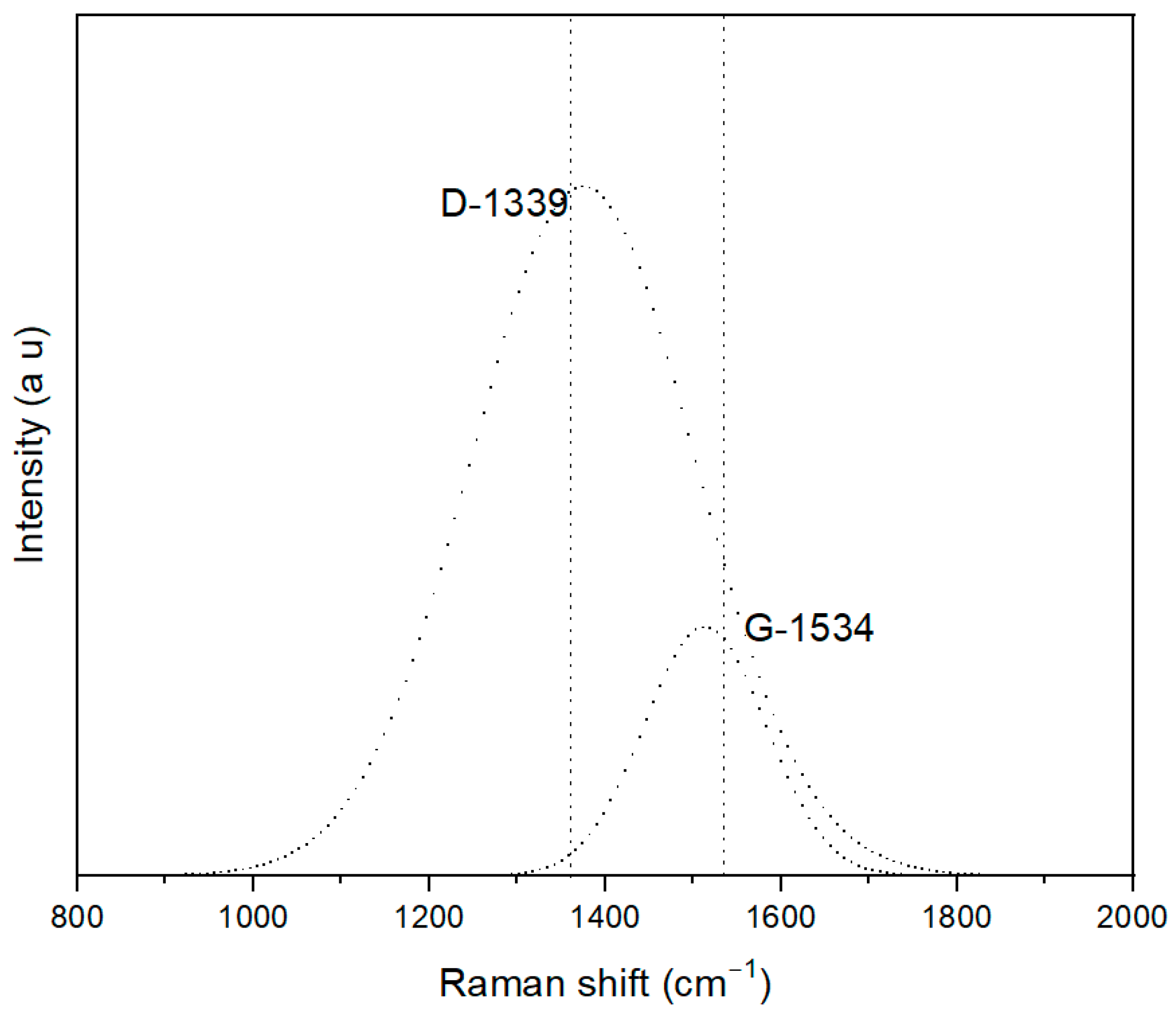
The Raman spectrum of the coating is observed in
Figure 1. A central band is observed, the sum of the D and G bands [
18]. Therefore, the widest band corresponds to 1339 cm
−1 related to sp
3 hybridization due to the vibrations of the dangling bond carbon atoms. On the other hand, the G band is related to the vibration of sp
2 hybridized carbon atoms in the hexagonal rings. The behaviour of these disordered carbons can be attributed to interstitial defects. In addition, the shift towards low values of the wave number of the G peak is related to the presence of bond angle disorder [
19].
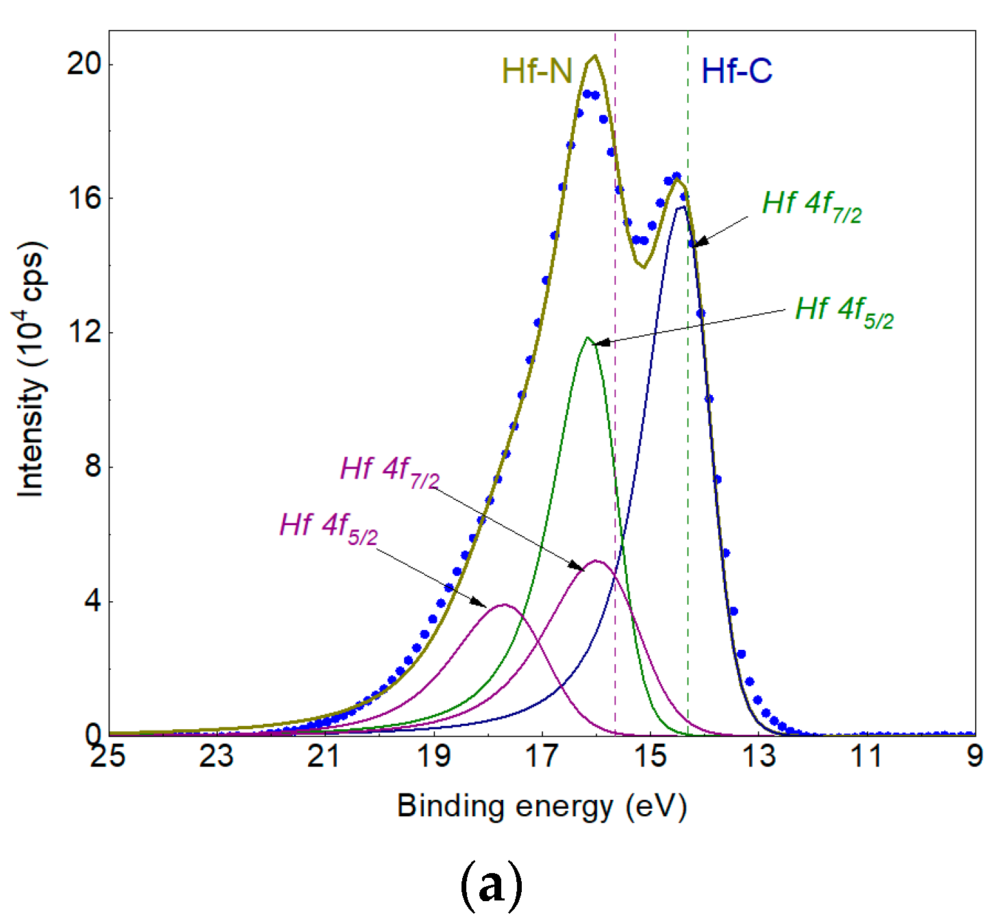
Figure 2 shows the spectrum of the HfCN coating formed on silicon substrates.
Table 2 identifies the characterisation of HfC and HfN and HfCN content. The characteristic peaks of the elements Hf, N, and C are observed. High-resolution spectra in XPS were used to detect the chemical states of Hf 4f
5/2 and Hf 4f
7/2. The 4f
5/2 and 4f
7/2 binding energy indicates the presence of HfN and HfC [
19]. In addition, the graph shows binding energies at the peaks located at 16.13 eV, 14.37 eV, 15.99 eV, and 17.70 eV, corresponding to the HfN [
20] compound. The results of the valence band study relate to the bulk metal states in sub-stoichiometric forms [
21]. From the changes in the basic levels for the bands, Hf 4d
5/2 and Hf 4f
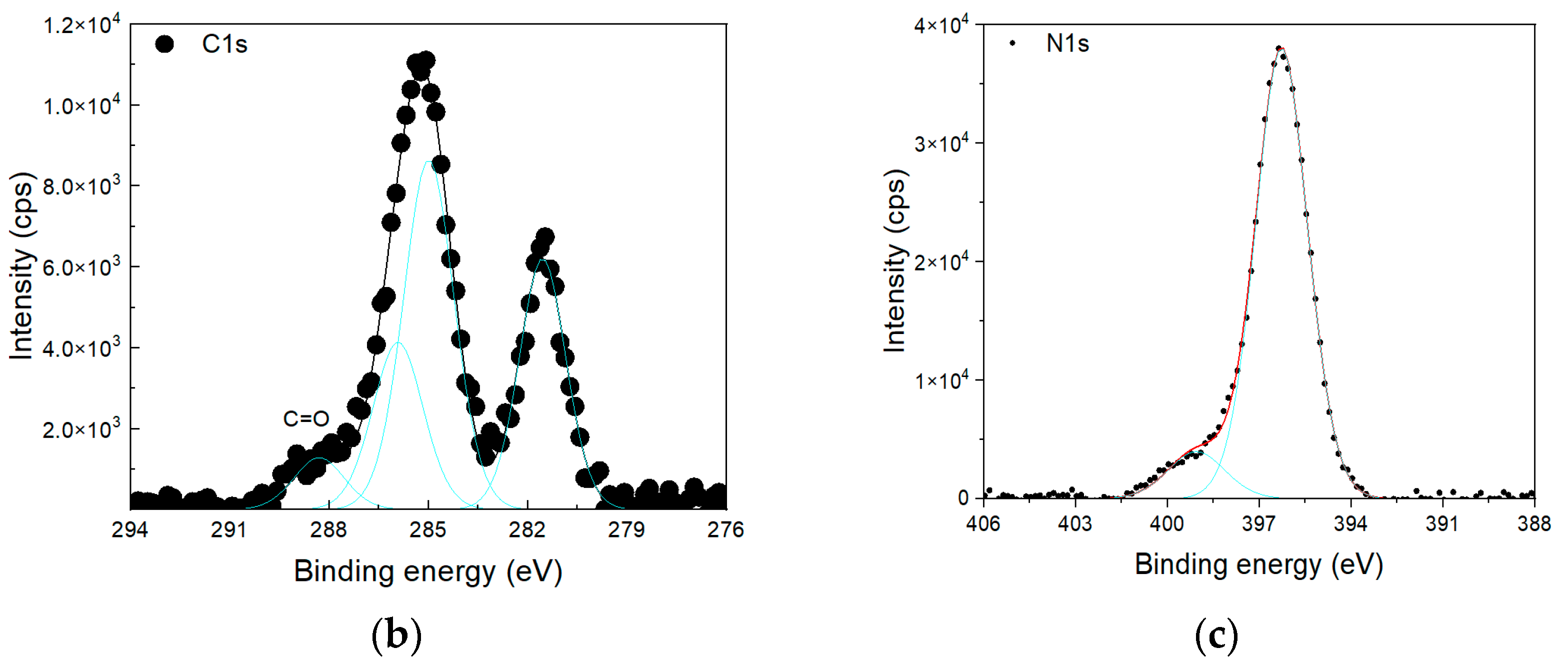
7/2, in their nominal stoichiometry Hf(CN), the composition HfN and HfC can be extrapolated. Furthermore, the apparent intensity of the 5/2 peak is lower than that of the 7/2 peak, a behaviour that indicates the contribution of carbon and nitrogen interstitially. High-resolution spectra for the N1s and C1s signal from the coating were determined at zero voltage.
Figure 2b shows the spectrum corresponding to C1s, and
Figure 2c shows the N1s signal, demonstrating the reaction of Hafnium with Carbon and Nitrogen to form the compound.
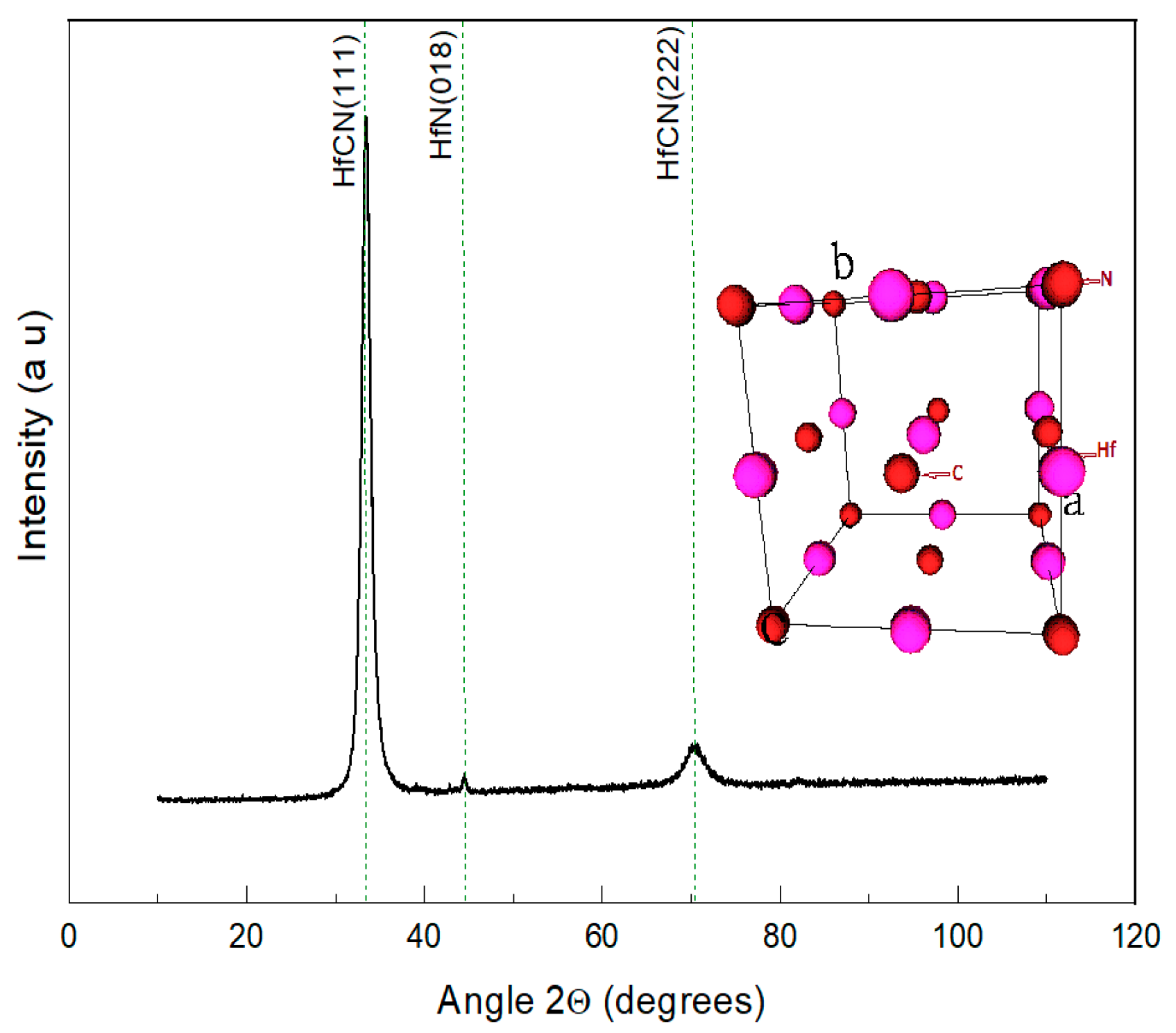
In
Figure 3, the diffraction pattern of the hafnium carbonitride coatings is shown. The phases present in the diffractogram were identified using the PDF4+ 2022 database. The indexing determined the peaks corresponding to the cubic HfCN compound (Spatial Group Fm
m No. 225) related to the crystallographic card No. 98-005-4921 [
22]. Additional peaks at 33.934° and 71.414° are evident, corresponding to the crystallographic planes (111) and (220), respectively, of the HfCN in the face-centered cubic (fcc) structure and the value of the lattice parameters a = b = c = 45.720 nm. In addition, a hexagonal HfN peak (Space Group R-3m No. 166) is reported in the diffractogram according to card No. 98-000-7881. The presence of the HfN compound is attributed to the low values of nitrogen density compared to carbon density. These differences in density make it easy for nitrogen to locate in the interstices [
23]. Based on the crystallographic information obtained, a Rietveld refinement was applied with the help of the X’Pert High Score Plus software to determine the percentages of phases present in the sample. The Rietveld method generated a calculated diffractogram, adjusted to the experimental diffractogram considering the structural and instrumental parameters [
24]. The results obtained to determine the percentages of phases by weight present in the were 97.2% HfCN and 2.8% HfN.
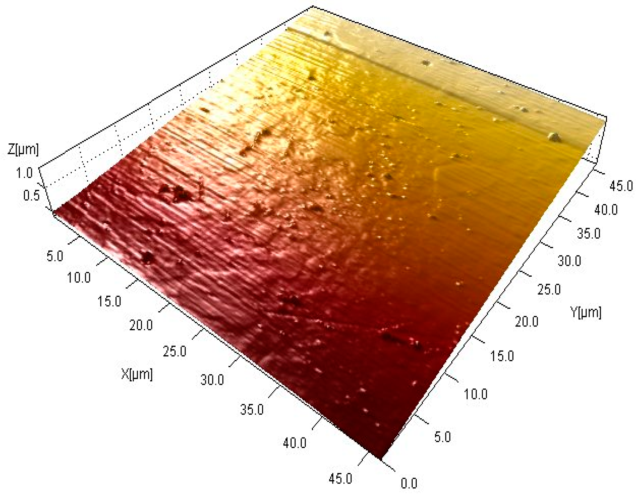
The results of the AFM technique of the HfCN coatings are shown in
Figure 4. No type of wear is observed on the surface of the coatings. The average roughness value was Sa = 207.67 nm. The topography of the coatings shows uniform grains and very small characteristics that determine the low value of surface roughness and can be classified as a smooth surface. In addition, the topographic description of the samples determined the similarity between the surface obtained with other carbon nitrides deposited by the PVD technique [
25]. This characteristic is attributed to applying negative bias voltages on the substrate surface, increasing the adsorbed atoms’ energy on the substrate surface [
26,
27]. Additionally, many nucleation sites are generated, reducing the grain sizes and, therefore, low total surface roughness.
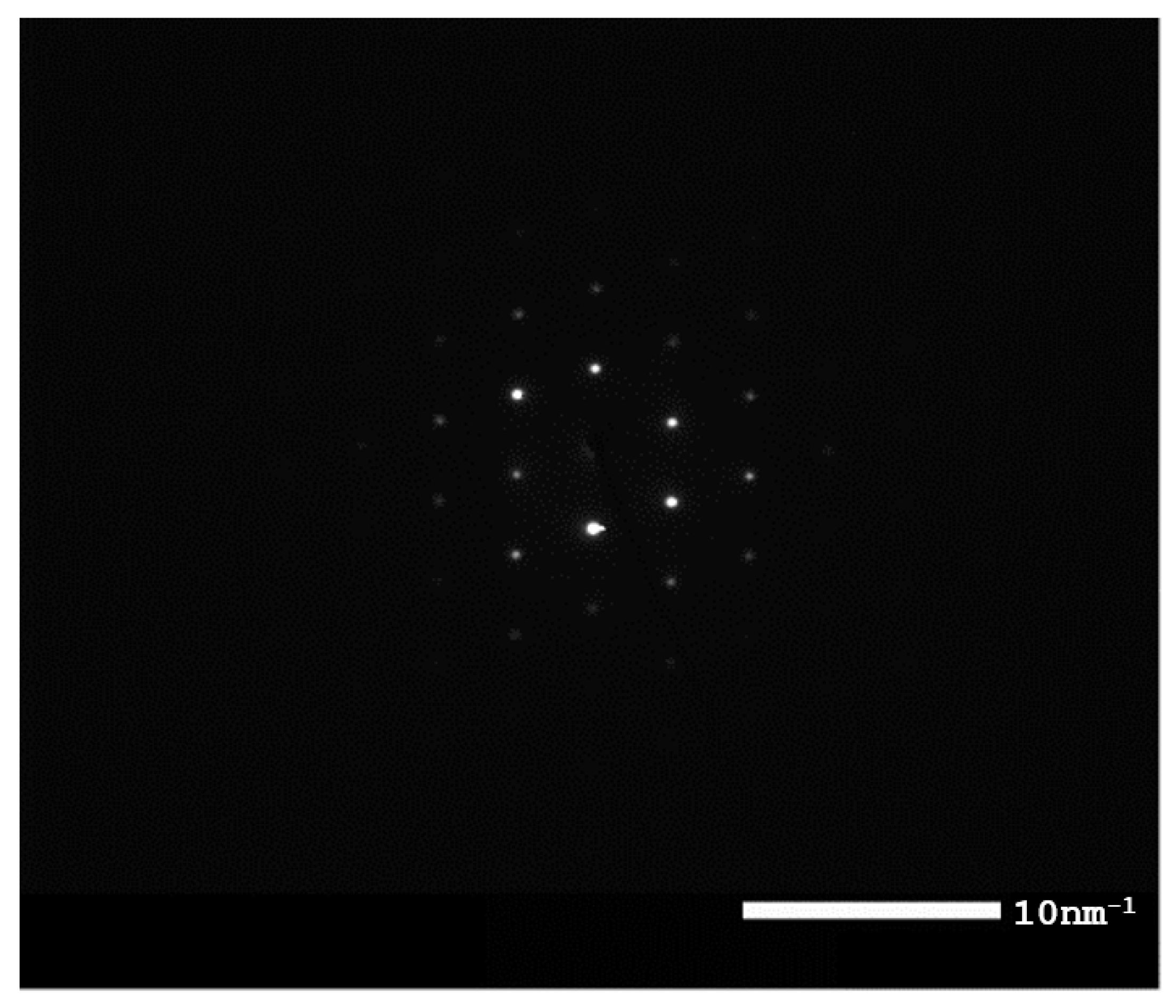
The transmission electron microscopy (TEM) technique corroborated the coatings’ crystallinity as shown in
Figure 5.
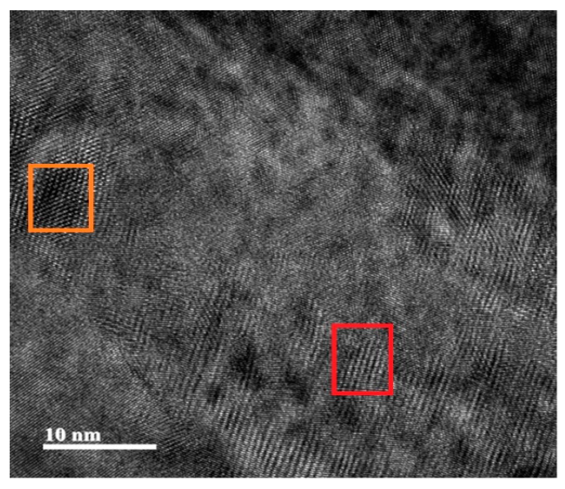
Using the TEM technique in bright field mode allowed us to know the orientation, crystallographic structure, and interplanar distances of the HfCN coatings [
28]. The results are shown in
Figure 6. Various orientations and the long-range order of the coating are observed in this Figure. Determining the interplanar distance in the crystal structure and the Fourier transform was also possible. According to the analysis carried out in the area demarcated in orange color (
Figure 6), the estimated interplanar distance was 2.6 Å, corresponding to the crystallographic plane (111) of the cubic HfCN. In the area marked with red color (
Figure 6), the interplanar distance has a value of 1.3 Å, corresponding to the crystallographic plane (222).
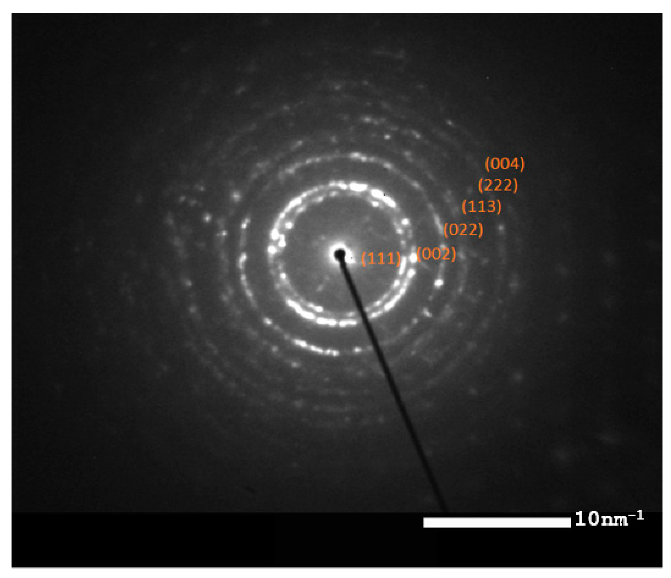
Different particle diffraction patterns were obtained to complement the structural analysis as shown in
Figure 7. The results show a diffraction pattern corresponding to polycrystalline material due to the presence of rings. The pattern was indexed and determined to correspond to HfCN according to crystallographic card 98-005-4921 [
18]. This result coincides with what was found in the XRD analysis. When performing the indexing, the crystallographic planes (111), (002), (022), (113), (222), and (004) were identified. According to the analysis, the first ring (plane (111)) corresponds to a cubic-type structure.
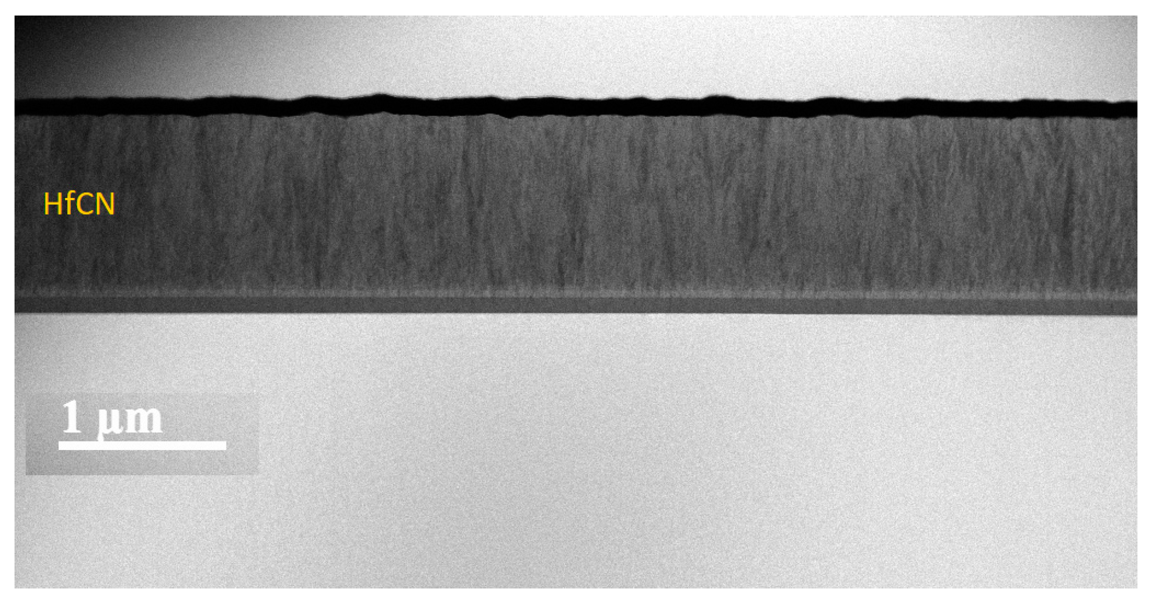
Figure 8 shows the SEM image of the cross-section of the HfCN layer coating. This image shows the layer–substrate interface and the homogeneity of the layer. Again, no cracks or deformations are observed.
Figure 9 shows the elastic behaviour due to the nano hardness test. The test consisted of making nine indentations on the surface of the HfCN coating deposited on the silicon substrate. The average value of nano hardness was 31.3 GPa [
17]. It is essential to highlight that hardness is directly related to wear resistance. In the case of multilayer coating applications, the interfaces are considered energy dissipation zones. This behaviour can be explained by mechanisms, such as the deflection of the cracks in the interface areas or local delamination at the interface through the opening of nanovoids, due to local stress relaxation and even nanoscale plasticity phenomena.
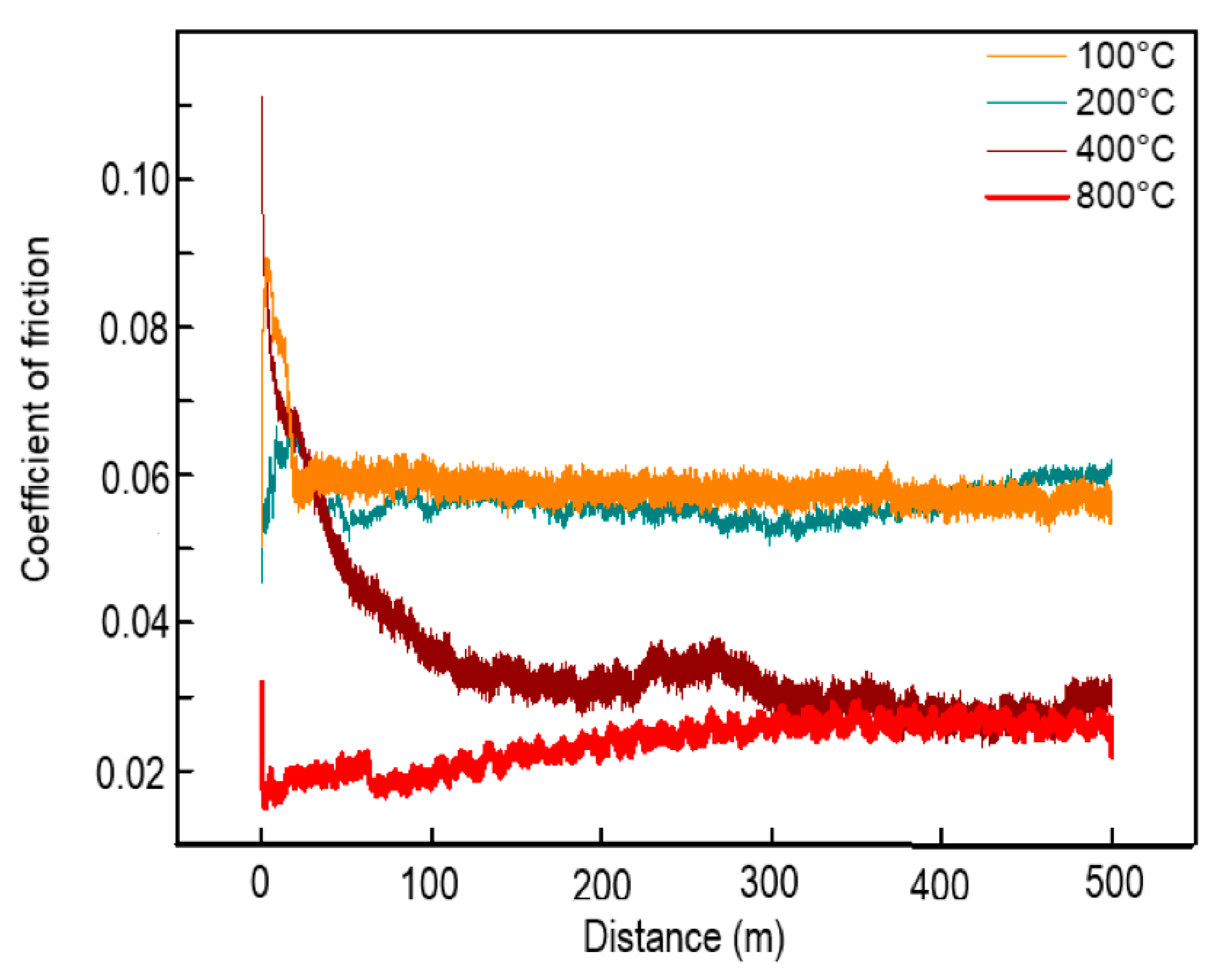
Figure 10 shows the coefficient of friction (COF) curves obtained at different temperatures. For example, at a temperature of 100 °C, the measurement of the coefficient of friction interrupted at 500 m in the HfCN coatings is observed. In the initial 10 m, the coefficient curve rises due to the polishing of roughness in areas of high surface heterogeneity (evidenced in the AFM test), forming grooves as wear marks. Subsequently, the COF value remains constant from 20 m to 500 m, showing a slight variation. The average value of the COF is 0.06. The variations of ±0.01 can be attributed to the generation of debris at the beginning of the test due to the low plastic resistance of the surface texture [
29]. The roughness was observed by AFM when determining the surface irregularity values of the coatings.
At 200 °C (
Figure 10), the study’s results established a lower initial friction force. Due to the increase in temperature in the system, the sliding contact, which is a function of the pin-coating contact area and the shear resistance, decreases, and the shear stress of the coating is higher. After 20 m of the test, low resistance to surface cutting is evident, causing a decrease in COF compared to what was observed at 100 °C [
30,
31]. This result allows us to infer that the increase in temperature in the HfCN coating favours the formation of microfilms that reduce wear in the coatings. The average value of the COF was 0.055.
At 400 °C (
Figure 10), a different behaviour is presented to that observed at temperatures of 100 °C and 200 °C. The dry sliding contact between the pin-coating creates a thermal variation distributed among the contact areas, establishing thermodynamic instability. Due to the high heat flux magnitude, a deterioration process is generated that leads to the formation of debris caused by the surface roughness of the coating. From 118 m on, the COF value decreases and later stabilizes. The average value of the COF was 0.035. By keeping the temperature constant, the energy flow is generated, expressly, by the contact between the asperities where the concentration of stresses and stresses produces an energy delta.
Finally, at 800 °C, an initial performance comparable to that of 400 °C is obtained. This behaviour is due to heat transfer around the apparent area of contact. However, at 800 °C, there is evidence of stability in the COF value. Therefore, according to the results obtained, it is possible to afford that the system’s thermal energy increase affects the work generated by the sliding between the pin and the HfCN coating with the real contact area. This characteristic contributes to the decrease in the COF value concerning the different temperatures evaluated. Therefore, at 800 °C in the coating, no accumulation of thermal energy is generated due to dissipation processes, as observed (
Figure 10) before 3 m from the start of the test.
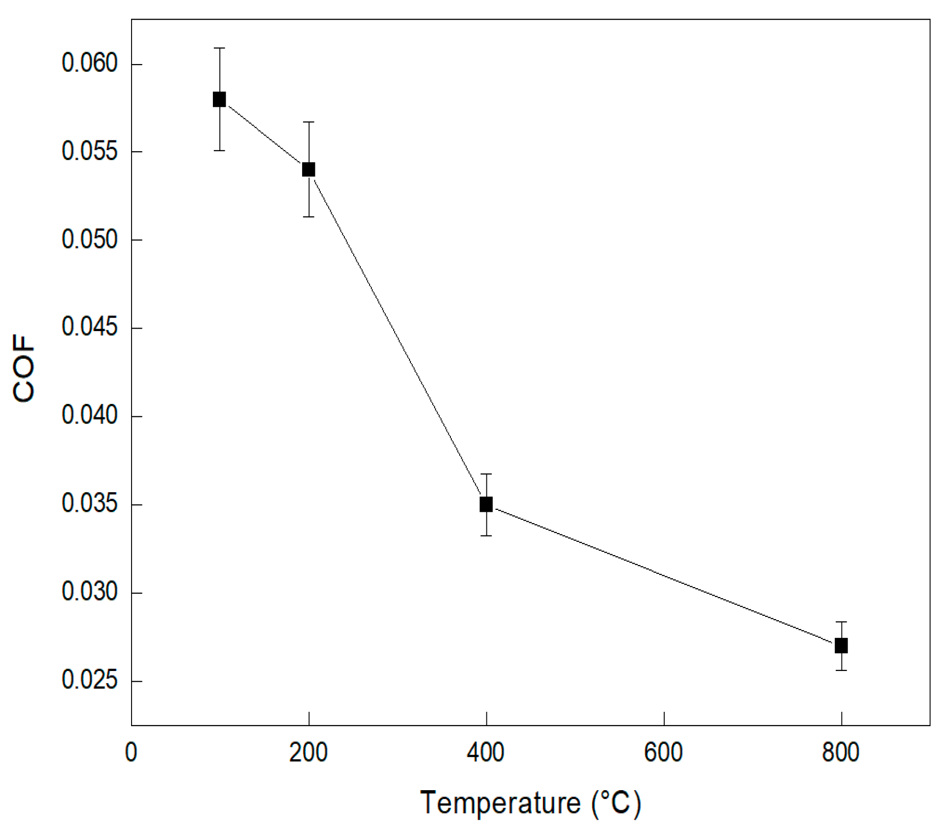
Figure 11 illustrated the COF values for the HfCN coatings as a function of temperature. It is observed that the COF decreases significantly with increasing temperature. The decrease in COF values is attributed to the optimal wear resistance provided by the coatings by reducing their plastic deformation.
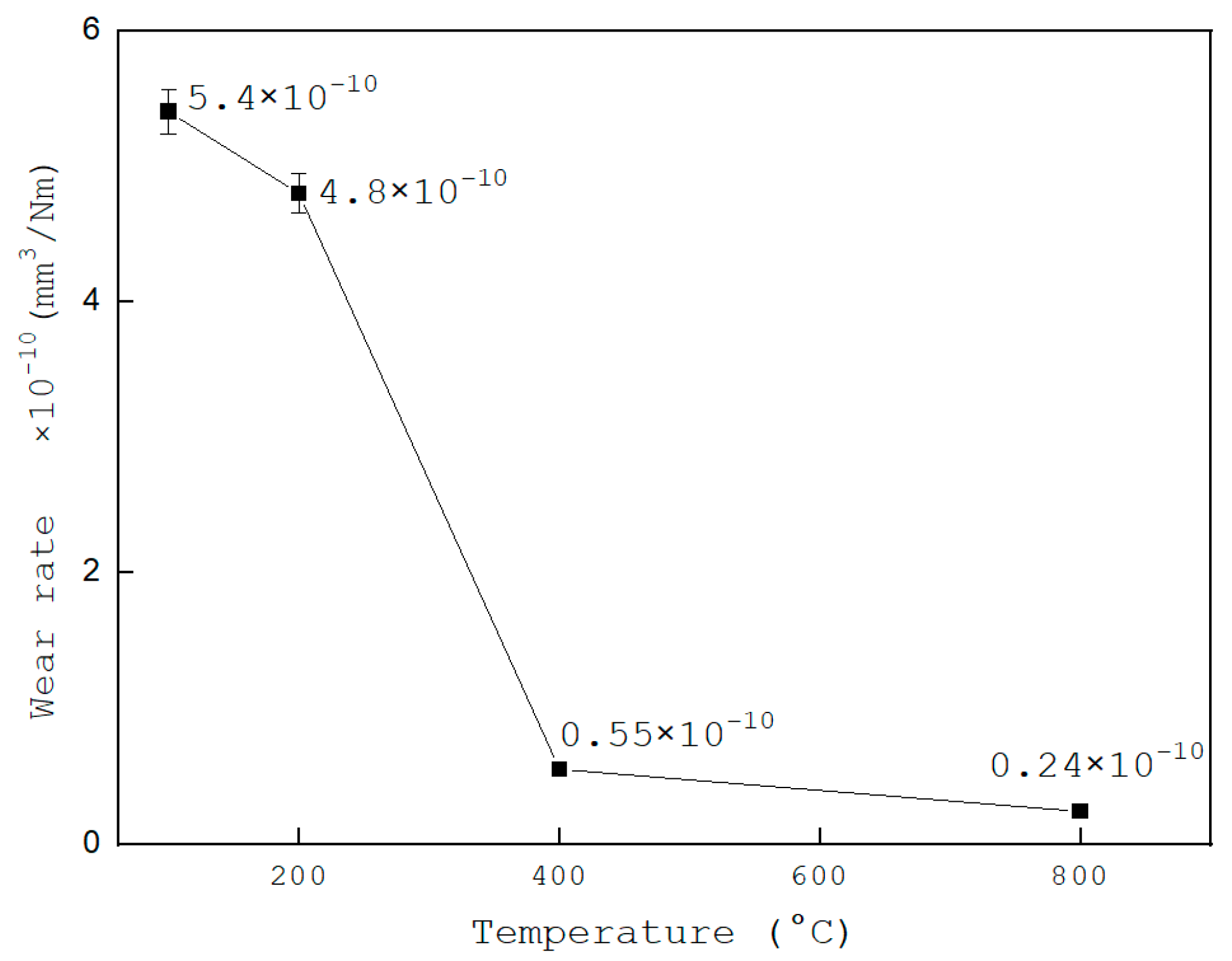
The result of wear can be seen in
Figure 12. The highest values of abrasive wear were recorded for the coatings evaluated at 100 °C with an average value of 5.48 × 10
−10 mm
3/Nm. The coatings evaluated at 800 °C presented the best anti-wear behavior with average values of 0.24 × 10
−10 mm
3/Nm. These results allow us to infer that the increase in temperature generates greater ductility in the coatings and, therefore, the resistance to abrasive wear is improved [
32,
33]. The results obtained from abrasive wear and COF allowed us to establish the effects of the treatment temperature of the coatings on their wear properties. In addition, the temperature modifies the chemical and physical processes related to wear phenomena. As the temperature increases, the surface roughness generates small contact areas. Therefore, the efforts are intensified in the roughness starting removal processes due to the fracture or fusion of the roughness. Subsequently, the abovementioned processes are stabilized, resulting in lower COF values.
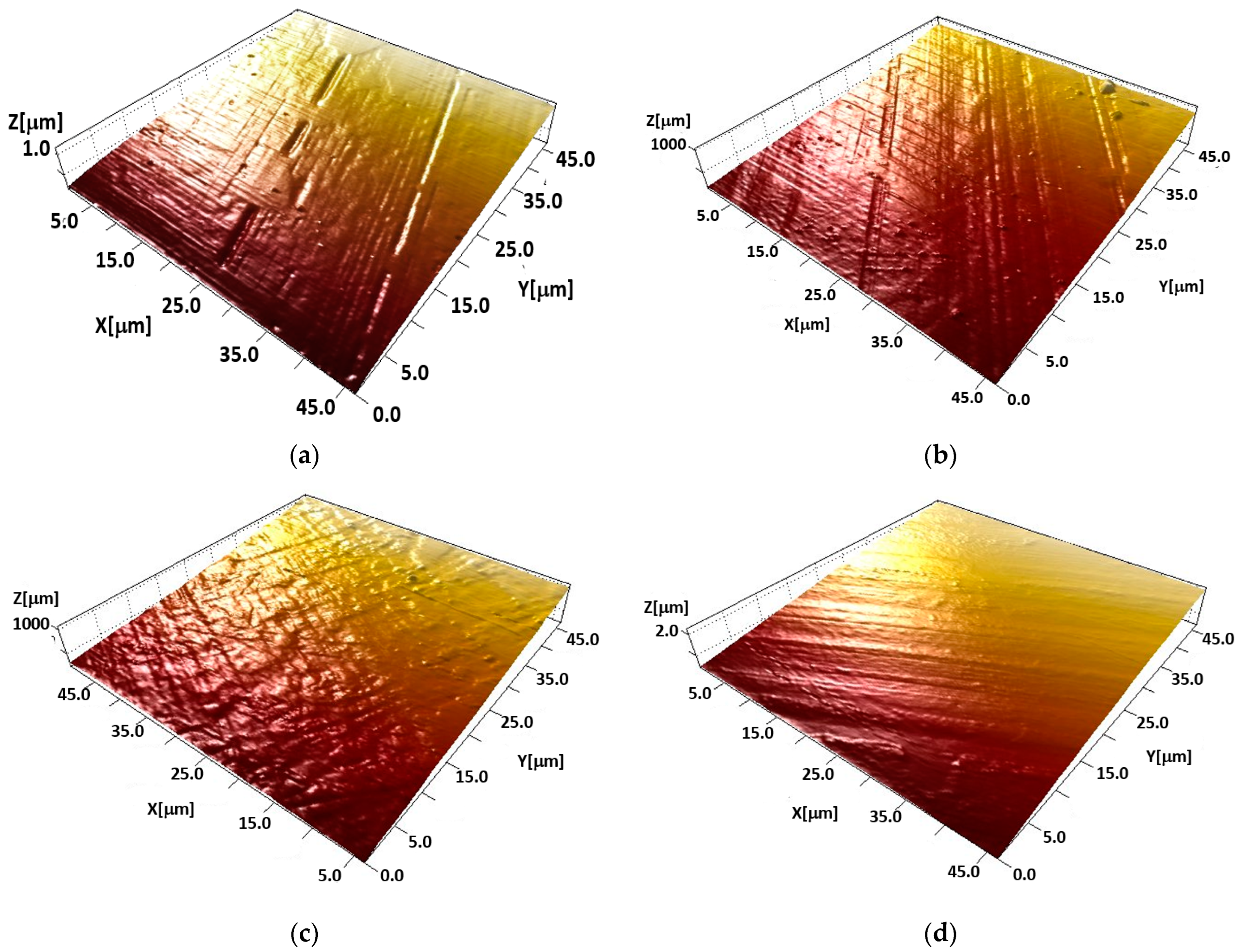
Figure 13 shows the surface micrographs obtained by AFM for each coating after performing the tribology test at different temperatures. When analysing the traces of superficial wear, the presence of grooves generated by the abrasive particles is observed. The most significant damage is exhibited by coatings exposed to 100 °C and 200 °C. The furrows in coatings evaluated at 400 °C and 800 °C are finer, shallower, and with minor wear; no deep marks are evident. In
Figure 13a and
Figure 13b, corresponding to coatings subjected to 100 °C and 200 °C, scratch patterns of various abrasive particles are observed. Wear is related to abrasion mechanisms due to the high hardness of the coating.
Figure 13c corresponds to coatings subjected to 400 °C, and wear traces related to micro-ploughing and micro-cracking mechanisms are evident. Micro-ploughing was produced by the displacement and accumulation of material before the abrasive particle, forming shallow grooves accompanied by slight plastic deformation. In addition, given the brittle nature of the coating due to temperature and the mechanical effect explained in the COF results, the formation of microcracks produced by high surface tension can be seen when the abrasive particles slide, causing material detachment.
Figure 13d shows the material tearing without a defined pattern of grooves. This behaviour evidences the phenomenon of micro fatigues due to the repetitive superficial ploughing of the loose particles of the same coating.
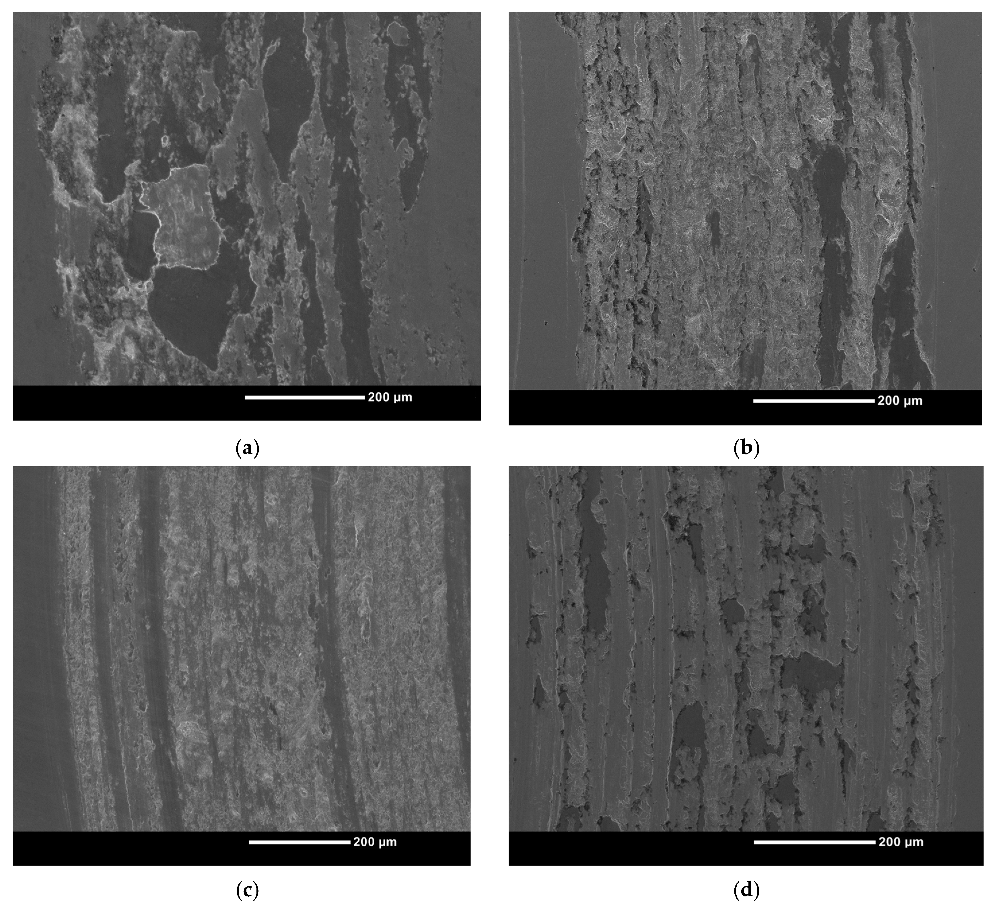
Figure 14 shows the SEM images obtained by the challenge-scattered electron technique for the coatings treated at temperatures of 100 °C (
Figure 14a), 200 °C (
Figure 14b), 400 °C (
Figure 14c), and 800 °C (
Figure 14d). The images show the wear track after the ball-on-disc test for the HfCN layers. In all the cases studied, traces of continuous and smooth wear with a groove depth less than the thickness of the layers. The analysis allows for establishing two types of wear mechanisms, abrasive, and adhesive. Abrasive wear is related to generating free wear particles generated by the Al
2O
3 ball or the coating. These particles interact with the coating causing gouges and scratches on the surface and generating high COF values. Adhesive wear is probably related to material transfer from the ball to the coating. In this study, abrasive wear is dominant at 100 °C and 200 °C. On the other hand, adhesive wear is dominant at temperatures greater than 400 °C.


