1. Introduction
Inconel 718 is a nickel-based superalloy that is widely used for high-temperature applications such as turbine blades, turbocharger rotors and nuclear reactors because of excellent mechanical properties as well as oxidation and corrosion resistance [
1,
2,
3].
Traditionally, Inconel 718 components are made by casting or forging. A feature of the microstructure of cast Inconel 718 is the segregation of alloying elements in the interdendritic regions and leads to the formation of an undesirable Laves phase, which requires multistage homogenization to dissolve [
4]. Forged Inconel 718 also needs post-processing to remove macro-segregation, for example using vacuum arc remelting [
5]. Thus, the cost of manufacturing products from Inconel 718 in the traditional way increases due to the need for post-processing, as well as the occurrence of scrap after machining [
2].
The advantages of additive manufacturing are the possibility of producing parts with complex shapes that are difficult or impossible to produce by traditional methods, a significant reduction in the production time of the final part and a reduction in the formation of scrap. Many researchers have already studied in detail the process parameters, microstructure and mechanical properties when manufacturing products from powder Inconel 718 by methods of selective laser melting (SLM) [
1,
6,
7,
8,
9,
10], electron-beam melting (EBM) [
11,
12,
13,
14] and direct laser deposition (DLD) [
15,
16]. At the same time, binder jetting (BJ) technology, which is promising and has been popular for the past few years in the production of ceramic and metal products [
17,
18,
19], is currently still not sufficiently studied [
20].
In [
2], three different Inconel 718 powders with average sizes of 7 μm, 21 μm and 70 μm were used for printing using the binder jetting method. The densification during sintering and microstructure of the produced samples were investigated. The analysis of the chemical compositions showed some variation in the content of the individual alloy components with respect to each other in the powders considered. This, in turn, led to different solidus and liquidus values being calculated by the software. It was shown that the liquidus temperature of the alloy with an average size of 21 μm in the initial powder was 30 and 40 °C higher than the powders with sizes 7 μm and 70 μm, respectively. All samples were sintered at 1290 °C for 5 h. Density measurements showed that the samples made from 7 μm and 70 μm powders had a relative density of 99.9%; this was in contrast to the sample made from a powder with an average size of 21 μm, which had a relative density of only 92%. The incomplete densification is attributed to sluggish diffusion kinetics due to the small volume fraction of the liquid phase (3%) compared with the samples made from powders of sizes 7 μm (35%) and 70 μm (40%). Complete densification of the sample made from the powder with an average size of 21 μm was achieved when the sintering temperature was increased to 1330 °C. The microstructure of the samples made from 7 μm and 21 μm powders was characterized by the absence of δ and Laves phases in contrast to the sample made from powder with an average size of 70 μm. It should be noted that the binder saturation level was lower (70%) during printing with the 70 μm powder compared with the 7 μm and 21 μm powders (80%). The higher binder saturation resulted in more residual carbon after debinding, which contributed to the formation of the MC phase instead of the δ and Laves phases.
In [
21], Inconel 718 superalloy powder with an average fraction of about 10–14 μm was used for printing by the binder jetting method. The relative density of sintered samples also had a direct dependence on the sintering temperature. The highest relative density, equal to 95%, was achieved after sintering at 1260 °C with dwell time of 3 h. Tensile tests were carried out for sintered samples, as well as after complex heat treatment. In the sintered state, the specimens did not achieve the ASTM F3055-14 target values for ultimate strength and yield strength. This behavior is expected, since Inconel 718 is a dispersion-strengthening alloy and without additional heat treatment not enough precipitates are formed to harden the material. After heat treatment, the yield strength was higher than the previously stated standard and close in value to ASTM B637-18. The ultimate strength increased after heat treatment but still did not reach the values required by the standards.
Improving the mechanical properties of superalloys is an essential aspect of manufacturing parts operating at high temperatures. In addition to complex heat treatments that promote the formation of intermetallic compounds in the matrix, one of the ways to solve this issue could be the creation of metal matrix composites (MMCs) based on superalloys.
Carbide ceramics have the most advantageous properties in terms of their use as the strengthening phase in composites. The advantages are high melting point, high strength even at high temperatures, high wear and corrosion resistance, low density and a high chemical stability. Titanium carbide (TiC) is one of the most important metal carbides used in modern materials science. TiC has a high melting point (3067 °C), high Young’s modulus (410–450 GPa) and high Vickers hardness (28–35 GPa) [
22]. TiC has a NaCl-type cubic crystal lattice with a parameter of 4.33 Å [
23]. Compared with titanium nitride (TiN), the addition of TiC as a strengthening phase in metal matrix composites results in higher sintered material density, higher strength characteristics and hardness [
24].
Due to the increased risk of global warming in recent years, reducing CO
2 emissions is an especially important issue. A significant share of emissions comes from various kinds of transport, including cars. The most effective solution is to reduce the weight of cars by using new, stronger materials. This is why many researchers are devoting their work to the development of advanced third-generation high-strength steel (AHSS) [
25]. The structure of these steels, such as Hardox 400 and Hardox 500, is martensitic with fine, regularly distributed, coherent carbides. Such a structure primarily increases yield strength, hardness and wear resistance [
26]. In paper [
25], the effect of the addition of TiC on the mechanical properties of the Fe–7%Mn alloy was investigated. The average crystallite size decreased when TiC was added to the alloy powders and the yield strength and hardness of the alloy were increased.
Infiltration and reactive sintering are the main types of technological processes for MMC manufacturing using binder jetting [
27].
In paper [
28], MMCs were obtained using a pressure infiltration process with an Inconel 718 melt of a porous ceramic billet made of TiC. The volume fraction of the strengthening phase was about 55%. The resulting composite material was 24% lighter than Inconel 718, and its hardness was almost 1.6 times higher that of Inconel 718. Tensile tests at room temperature showed a resulting ultimate strength of about 819 MPa, which is probably due to the high content of the strengthening phase. The infiltration technology itself implies a high-volume fraction of ceramics in the composite, which results in rather low values for tensile strength and relative elongation of the tested material. Thus, based on the characteristic mechanical properties and heterogeneous microstructure, this method cannot be used for particularly responsible applications [
2].
In [
29], MMCs were obtained by reactive sintering, namely due to in situ synthesis of carbides of alloying elements of Inconel 625 during sintering due to the use of a carbon-containing binder during printing by binder jetting. The sintering process conditions influenced phase composition, morphology and the distribution of carbides. When an inert atmosphere was used throughout the sintering process, the structure consisted of a nickel matrix core with NbC, Mo
2C and Cr
3C
2 phases and a shell consisting of Cr
3C
2. The use of a reducing atmosphere at the debinding stage led to the formation of a core structure without a shell of Cr
3C
2. The authors suggest that a change in the amount of carbon remaining after the debinding stage can be used to change the morphology and composition of the MMC; however, this method does not allow prediction of the exact quantitative ratio of the strengthening phase and the matrix metal and, consequently, the properties of the final MMC.
The authors of [
30] describe the fabrication of an in situ synthesized MMC by hot pressing. Inconel 718 superalloy was used as a metal matrix to which 5 to 15 vol.% Ti
2AlC was added. Exposure to high temperature contributed to the formation of ultradispersed TiC particles evenly distributed in the matrix. The composite made with the addition of 5 vol.% Ti
2AlC had the best properties. At room temperature the ultimate strength of the MMC was 1410 MPa. At 700 °C the ultimate strength of the MMC was 1010 MPa, which was higher than the ultimate strength of the superalloy Inconel 718 by almost 15%.
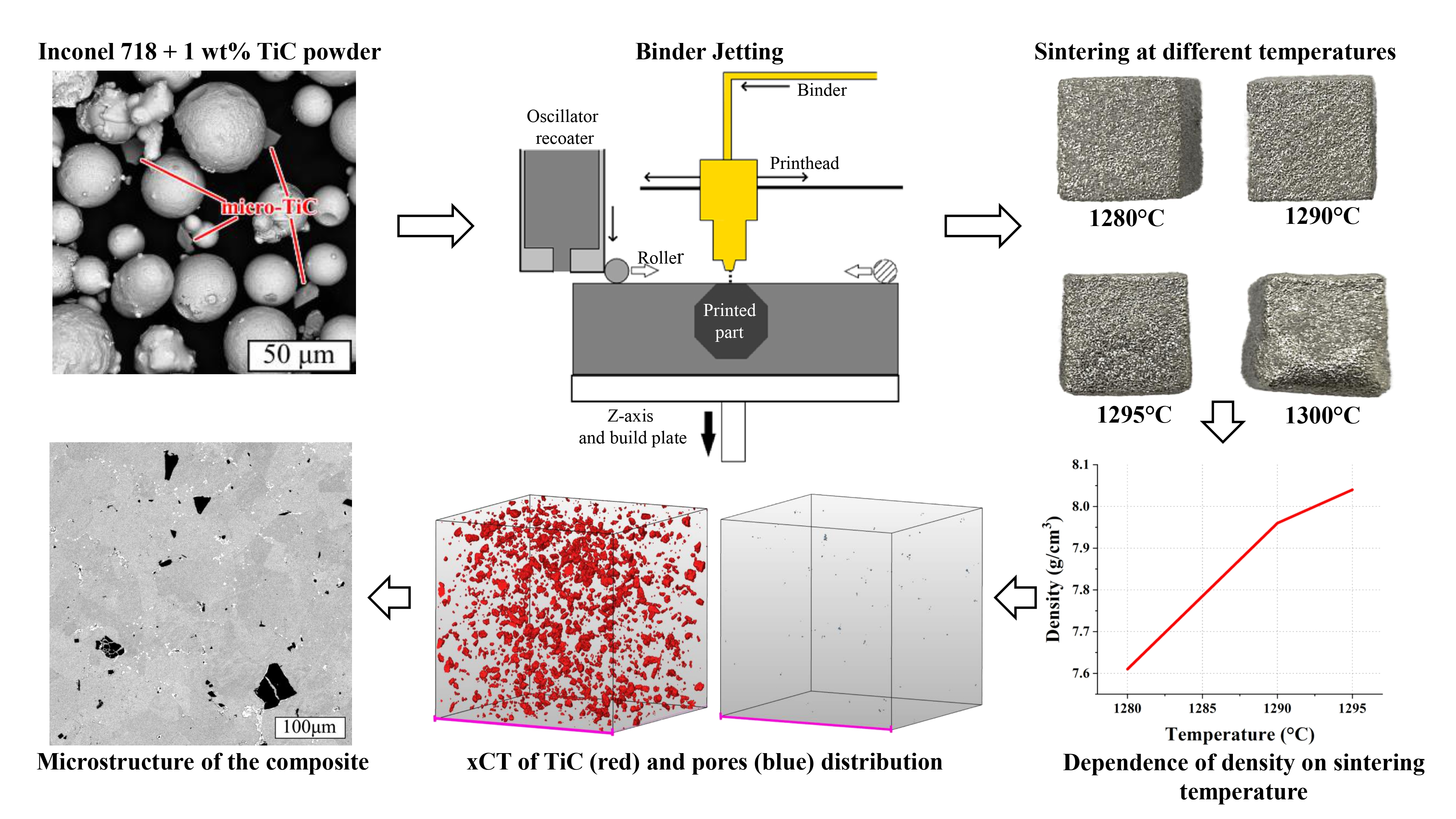
Previously published papers have not investigated the effect of the particle size of the strengthening phase in the fabrication of Inconel 718 and TiC-based MMCs using binder jetting. In the present research, it was decided to fabricate an MMC by adding 1 wt% TiC to Inconel 718 superalloy matrix and investigate the effect of TiC particle size on the microstructure and mechanical properties of the received MMC at different temperatures. The studies were carried out for sintered billets as well as for samples after additional postprocessing by hot isostatic pressing (HIP) and heat treatment (HT).
2. Materials and Methods
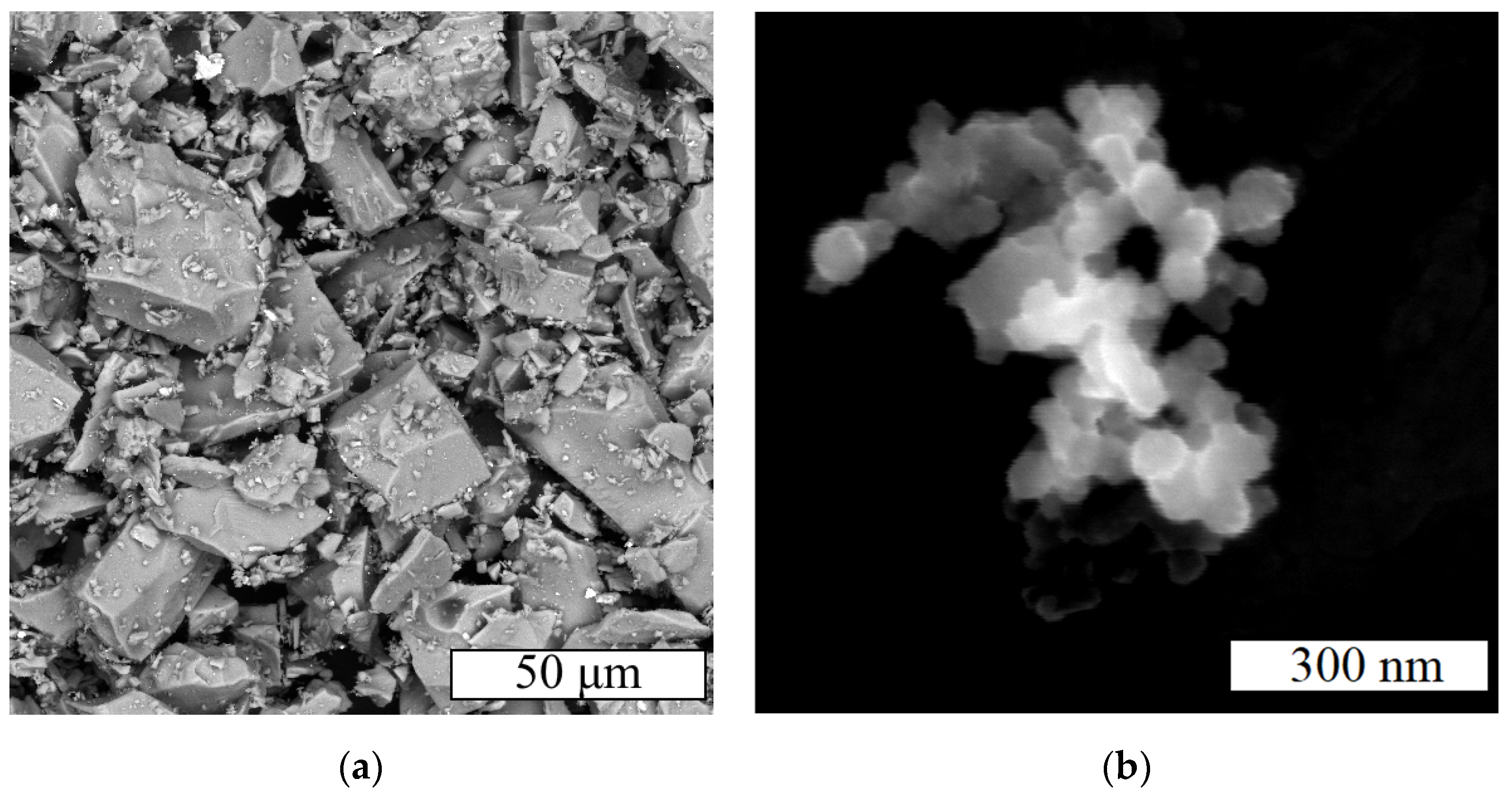
Inconel 718 powders (MetcoAdd 718C, Oerlicon, Pfäffikon, Switzerland), micron-sized TiC (which consists of polyhedral particles with a mean size of 17.1 microns) and nano-sized TiC (representing agglomerations of spherical particles with a mean size of 60 nm) (Sigma-Aldrich, St. Louis, MO, USA) were used as initial materials in this study. The chemical composition of Inconel 718 powder is shown in
Table 1 [
31]. The particle morphologies of micron- and nano-sized TiC powders are shown in
Figure 1.
Powder mixtures of Inconel 718 and 1% TiC were prepared using a gravity mixer for 12 h.
The flowability of powders was determined using a Hall flowmeter. Determination of the apparent density of powders consisted of measuring the mass of the powder, which, in a free-flowing state, filled a container of known volume (25 cm3).
To determine the particle size distribution of the powder, we applied a laser diffraction method using an Analysette 22 NanoTec plus analyzer (Fritsch GmbH, Idar-Oberstein, Germany) with a measuring range of 0.01–2000 µm.
The powder morphology and microstructure of the obtained samples were studied using a Tescan Mira3 LMU (Brno, Czech Republic) scanning electron microscope (SEM), as well as a Leica DMI5000 optical microscope (Leica Microsystems, Germany). A 1:3 mixture of HNO3 and HCl with the addition of a drop of HF was used to etch the samples.
The samples were made using the ExOne Innovent binder jetting system (The ExOne Company, North Huntington, PA, USA).
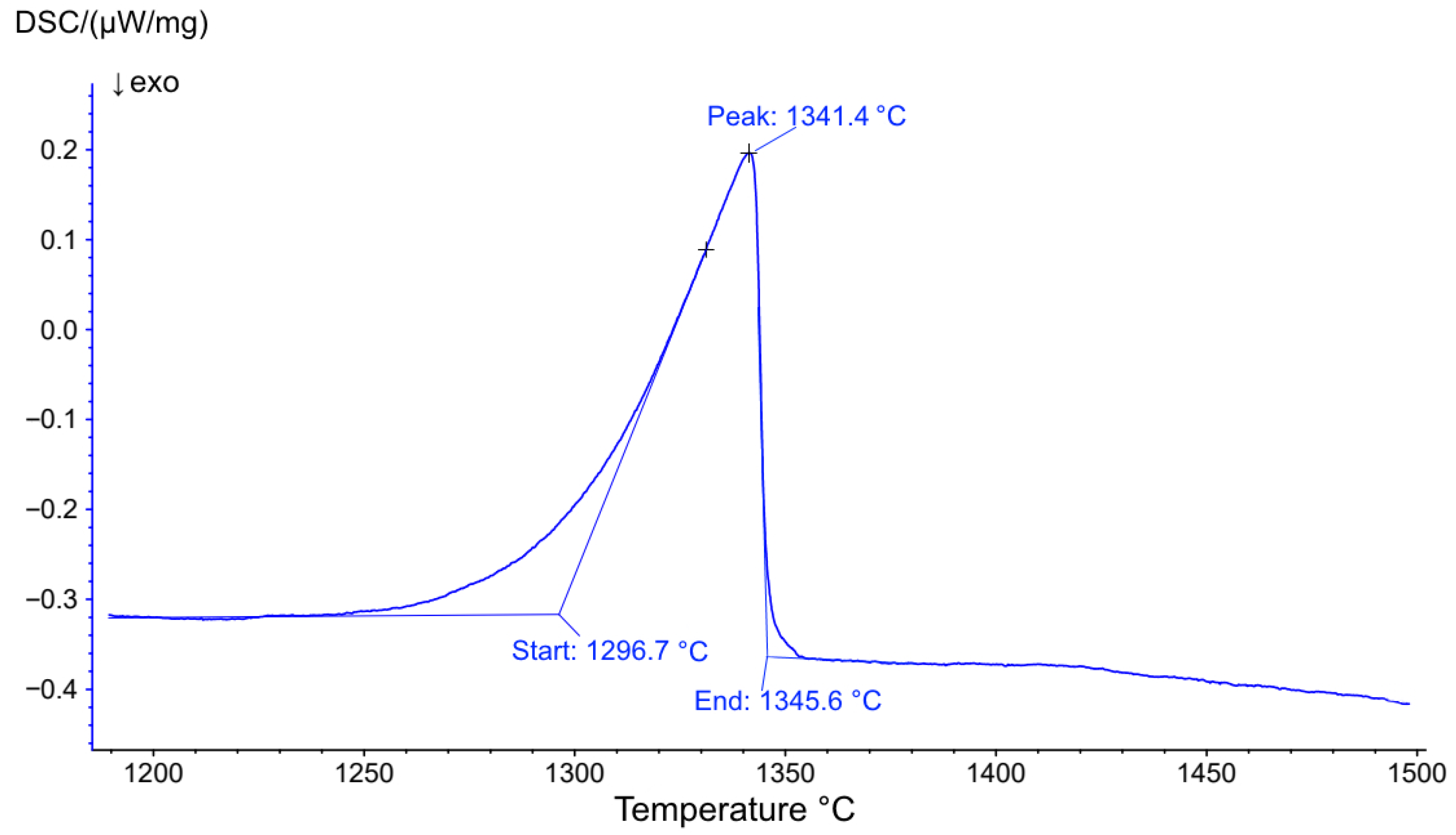
Differential scanning calorimetry (DSC) was used to determine the solidus temperature of the Inconel 718 superalloy, which was necessary to select the sintering temperature.
Phase analysis was performed using a Bruker D8 Advance X-ray diffractometer (XRD) (Billerica, MA, USA) using Cu-Kɑ (1/4 1.5418 Å) irradiation.
Hot isostatic pressing (HIP) was applied at 1160 °C and 130 MPa for 3 h in an argon atmosphere. The heat treatment (HT) of the samples was an annealing at 1060 °C with a holding time of 1 h followed by air cooling and aging. The aging included heating to 760 °C and holding for 10 h, then cooling to 650 °C for 2 h and holding at 650 °C for 8 h followed by air cooling. A Phoenix V|tome|x M300 high-resolution industrial computer tomographic system (Waygate Technologies, Wunstorf, Germany) was used for the X-ray microtomography analysis (xCT) of the samples.
The densities of the sintered samples and the samples after HIP were determined by the Archimedes method in water with the addition of a surfactant.
The hardness of the samples was determined using a Zwick/Roell Zhu hardness tester (Zwick Roell GmbH & Co., Ulm, Germany) using the Vickers method.
Tensile tests to determine the ultimate strength, yield strength and relative elongation were performed using Zwick/Roell z100 testing machines at room temperature and Zwick/Roell z050 at 700 °C (ZwickRoell GmbH & Co., Ulm, Germany).
Author Contributions
Conceptualization, V.S.; methodology, V.S. and A.B.; software, A.B.; validation, V.S., A.B. and D.E.; formal analysis, A.B. and D.E.; investigation, A.B. and D.E.; resources, V.S. and A.P.; data curation, A.B.; writing—original draft preparation, D.E.; writing—review and editing, V.S. and A.B.; visualization, A.B.; supervision, V.S.; project administration, V.S.; funding acquisition, V.S. and A.P. All authors have read and agreed to the published version of the manuscript.
Funding
The research was funded by the Ministry of Science and Higher Education of the Russian Federation: “Agreement on the grant in the form of subsidies from the federal budget for the implementation of state support for the creation and development of world-class scientific centers, those are performing research and development on the priorities of scientific and technological development”, dated 20 April 2022, no. 075-15-2022-311.
Data Availability Statement
Not applicable.
Acknowledgments
The authors thank the OSTEC-SMT company for the X-ray computed tomography analysis.
Conflicts of Interest
The authors declare no conflict of interest.
References
- Jia, Q.; Gu, D. Selective laser melting additive manufacturing of Inconel 718 superalloy parts: Densification, microstructure and properties. J. Alloys Compd. 2014, 585, 713–721. [Google Scholar] [CrossRef]
- Nandwana, P.; Elliott, A.M.; Siddel, D.; Merriman, A.; Peter, W.H.; Babu, S.S. Powder bed binder jet 3D printing of Inconel 718: Densification, microstructural evolution and challenges. Curr. Opin. Solid State Mater. Sci. 2017, 21, 207–218. [Google Scholar] [CrossRef]
- Sufiiarov, V.S.; Popovich, A.A.; Borisov, E.V.; Polozov, I.A. Evolution of structure and properties of heatresistant nickel alloy after selective laser melting, hot isostatic pressing and heat treatment. Tsvetnye Met. 2017, 1, 77–82. [Google Scholar] [CrossRef]
- Radavich, J.F. The Physical Metallurgy of Cast and Wrought Alloy 718. Superalloy 2012, 718, 229–240. [Google Scholar] [CrossRef]
- Ganji, D.K.; Rajyalakshmi, G. Influence of Alloying Compositions on the Properties of Nickel-Based Superalloys: A Review. Recent Adv. Mech. Eng. Sel. Proc. NCAME 2020, 653, 537–555. [Google Scholar] [CrossRef]
- Teng, Q.; Li, S.; Wei, Q.; Shi, Y. Investigation on the influence of heat treatment on Inconel 718 fabricated by selective laser melting: Microstructure and high temperature tensile property. J. Manuf. Process. 2021, 61, 35–45. [Google Scholar] [CrossRef]
- Wang, Z.; Guan, K.; Gao, M.; Li, X.; Chen, X.; Zeng, X. The microstructure and mechanical properties of deposited-IN718 by selective laser melting. J. Alloys Compd. 2012, 513, 518–523. [Google Scholar] [CrossRef]
- Chlebus, E.; Gruber, K.; Kuźnicka, B.; Kurzac, J.; Kurzynowski, T. Effect of heat treatment on the microstructure and mechanical properties of Inconel 718 processed by selective laser melting. Mater. Sci. Eng. A 2015, 639, 647–655. [Google Scholar] [CrossRef]
- Sufiyarov, V.S.; Borisov, E.V.; Polozov, I.A.; Masailo, D.V. Control of structure formation in selective laser melting process. Tsvetnye Met. 2018, 7, 68–74. [Google Scholar] [CrossRef]
- Popovich, A.A.; Sufiiarov, V.S.; Borisov, E.V.; Polozov, I.A.; Masaylo, D.V. Design and manufacturing of tailored microstructure with selective laser melting. Mater. Phys. Mech. 2018, 38, 1–10. [Google Scholar] [CrossRef]
- Pollock, T.M.; Tin, S. Nickel-Based Superalloys for Advanced Turbine Engines: Chemistry, Microstructure, and Properties. J. Propuls. Power 2006, 22, 361–374. [Google Scholar] [CrossRef]
- Kotzem, D.; Dumke, P.; Sepehri, P.; Tenkamp, J.; Walther, F. Effect of miniaturization and surface roughness on the mechanical properties of the electron beam melted superalloy Inconel 718. Prog. Addit. Manuf. 2020, 5, 267–276. [Google Scholar] [CrossRef]
- Strondl, A.; Palm, M.; Gnauk, J.; Frommeyer, G. Microstructure and Mechanical Properties of Nickel Based Superalloy IN718 Produced by Rapid Prototyping with Electron Beam Melting (EBM). Mater. Sci. Technol. 2011, 27, 876–883. [Google Scholar] [CrossRef]
- Kirka, M.M.; Unocic, K.A.; Raghavan, N.; Medina, F.; Dehoff, R.R.; Babu, S.S. Microstructure Development in Electron Beam-Melted Inconel 718 and Associated Tensile Properties. JOM 2016, 68, 1012–1020. [Google Scholar] [CrossRef]
- Blackwell, P.L. The mechanical and microstructural characteristics of laser-deposited IN718. J. Mater. Process. Technol. 2005, 170, 240–246. [Google Scholar] [CrossRef]
- Petrat, T.; Brunner-Schwer, C.; Graf, B.; Rethmeier, M. Microstructure of Inconel 718 parts with constant mass energy input manufactured with direct energy deposition. Procedia Manuf. 2019, 36, 256–266. [Google Scholar] [CrossRef]
- Sufiiarov, V.; Kantyukov, A.; Popovich, A.; Sotov, A. Structure and properties of barium titanate lead-free piezoceramic manufactured by binder jetting process. Materials 2021, 14, 4419. [Google Scholar] [CrossRef]
- Sufiiarov, V.; Kantyukov, A.; Popovich, A.; Sotov, A. Synthesis of Spherical Powder of Lead-Free BCZT Piezoceramics and Binder Jetting Additive Manufacturing of Triply Periodic Minimum Surface Lattice Structures. Materials 2022, 15, 6289. [Google Scholar] [CrossRef]
- Sufiiarov, V.; Polozov, I.; Kantykov, A.; Khaidorov, A. Binder jetting additive manufacturing of 420 stainless steel: Densification during sintering and effect of heat treatment on microstructure and hardness. Mater. Today Proc. 2019, 30, 592–595. [Google Scholar] [CrossRef]
- Li, M.; Du, W.; Elwany, A.; Pei, Z.; Ma, C. Metal binder jetting additive manufacturing: A literature review. J. Manuf. Sci. Eng. Trans. 2020, 142, 090801. [Google Scholar] [CrossRef]
- Eriksson, T. Process Optimization and Characterization of Inconel 718 Manufactured by Metal Binder Jetting. Master‘s Thesis, Luleå University of Technology, Luleå, Sweden, 2021. [Google Scholar]
- Li, R. Synthesis and Structure of a New Mixed Cuprate-Titanate: La2Sr4Cu2Ti2O13. Mater. Res. Bull. 1996, 31, 539–543. [Google Scholar] [CrossRef]
- The Materials Project. Available online: https://Next-Gen.Materialsproject.Org/Materials/Mp-631?Formula=TiC (accessed on 1 July 2023).
- Gülsoy, H.O.; Gunay, V.; Baykara, T. Influence of TiC, TiN and TiC (N) Additions on Sintering and Mechanical Properties of Injection Moulded Titanium Based Metal Matrix Composites. Powder Metall. 2015, 58, 30–35. [Google Scholar] [CrossRef]
- Jeon, J.; Choi, S.; Seo, N.; Moon, Y.H.; Shon, I.J.; Lee, S.J. Effects of TiC Addition on Strain-Induced Martensite Transformation and Mechanical Properties of Nanocrystalline Fe-Mn Alloy Fabricated by Spark Plasma Sintering. Arch. Metall. Mater. 2020, 65, 1249–1254. [Google Scholar] [CrossRef]
- Frydman, S.; Pękalski, G. Modern Low-Alloy Wear-Resistant Steels-Structure And Impact Strength. Int. Sci. J. Mach. Technol. Mater. 2010, 4, 45–46. [Google Scholar]
- Srivatsan, T.S.; Harrigan, W.C., Jr.; Murph, S.H. Metal-matrix Composites; Springer Nature: Cham, Switzerland, 2021; pp. 65–74. [Google Scholar]
- Cho, S.; Lee, Y.H.; Ko, S.; Park, H.; Lee, D.; Shin, S.; Lee, S.K. Microstructure and Properties of TiC-Inconel 718 Metal Matrix Composites Fabricated by Liquid Pressing Infiltration Process. Compos. Res. 2019, 32, 158–162. [Google Scholar] [CrossRef]
- Enrique, D.; Mahmoodkhani, Y.; Marzbanrad, E.; Toyserkani, E.; Zhou, N.Y. In situ formation of metal matrix composites using binder jet additive manufacturing (3D printing). Mater. Lett. 2018, 232, 179–182. [Google Scholar] [CrossRef]
- Hu, W.; Huang, Z.; Yu, Q.; Wang, Y.; Jiao, Y.; Lei, C.; Zhou, Y. Ti2AlC triggered in-situ ultrafine TiC / Inconel 718 composites: Microstructure and enhanced properties. J. Mater. Sci. Technol. 2020, 51, 70–78. [Google Scholar] [CrossRef]
- Oerlikon Metco, MetcoAdd 718C. Available online: https://mymetco-europe.oerlikon.com/en-us/product/metcoadd718c (accessed on 5 July 2023).
- Turker, M.; Godlinski, D.; Petzoldt, F. Effect of production parameters on the properties of IN 718 superalloy by three-dimensional printing. Mater. Charact. 2008, 59, 1728–1735. [Google Scholar] [CrossRef]
- Sicre-Artalejo, J.; Petzoldt, F.; Campos, M.; Torralba, J.M. High-density inconel 718: Three-dimensional printing coupled with hot isostatic pressing. Int. J. Powder Metall 2008, 44, 35–43. [Google Scholar]
- Luu, D.N.; Zhou, W.; Nai, S.M.L.; Yang, Y. Mitigation of solute segregation during solutionization of selective laser melted Inconel 718 through micron-TiC addition. J. Alloys Compd. 2022, 897, 163224. [Google Scholar] [CrossRef]
- Sufiiarov, V.; Erutin, D.; Borisov, E.; Popovich, A. Selective Laser Melting of Inconel 718/TiC Composite: Effect of TiC Particle Size. Metals 2022, 12, 1729. [Google Scholar] [CrossRef]
Figure 1.
SEM images of powders: micron-sized TiC (a) and nano-sized TiC (b).
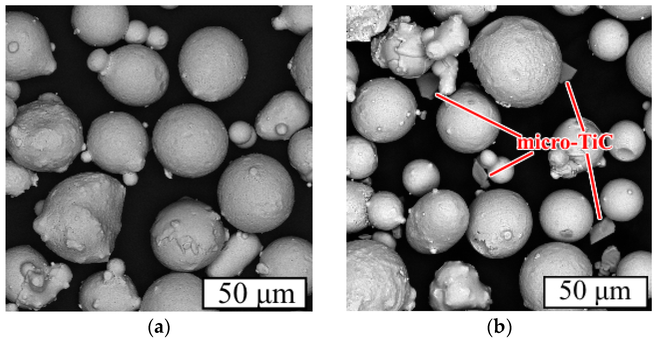
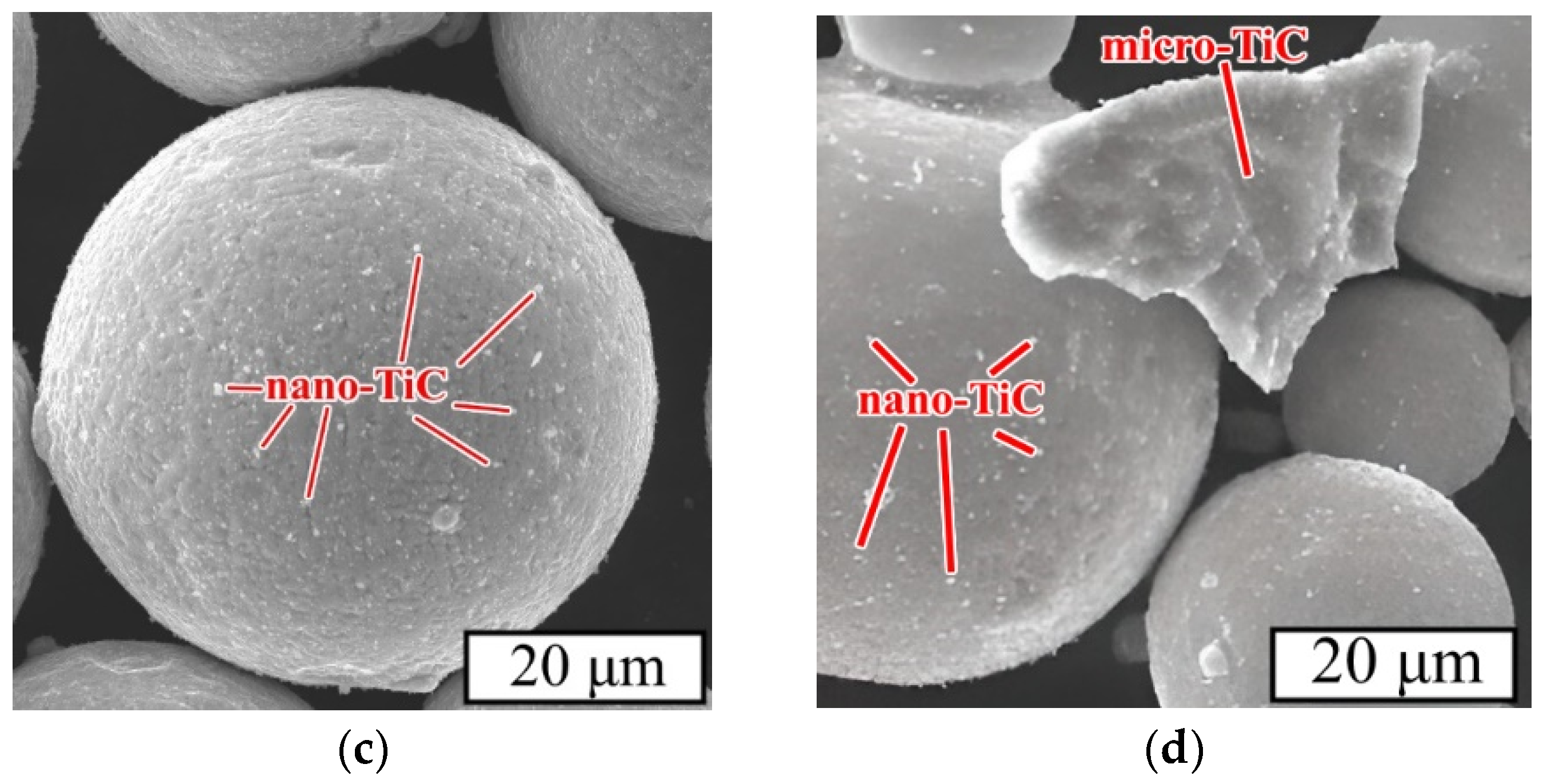
Figure 2.
SEM images of the powders: INC (BSE) (a), INC-m (BSE) (b), INC-n (SE) (c) and INC-mn (SE) (d).
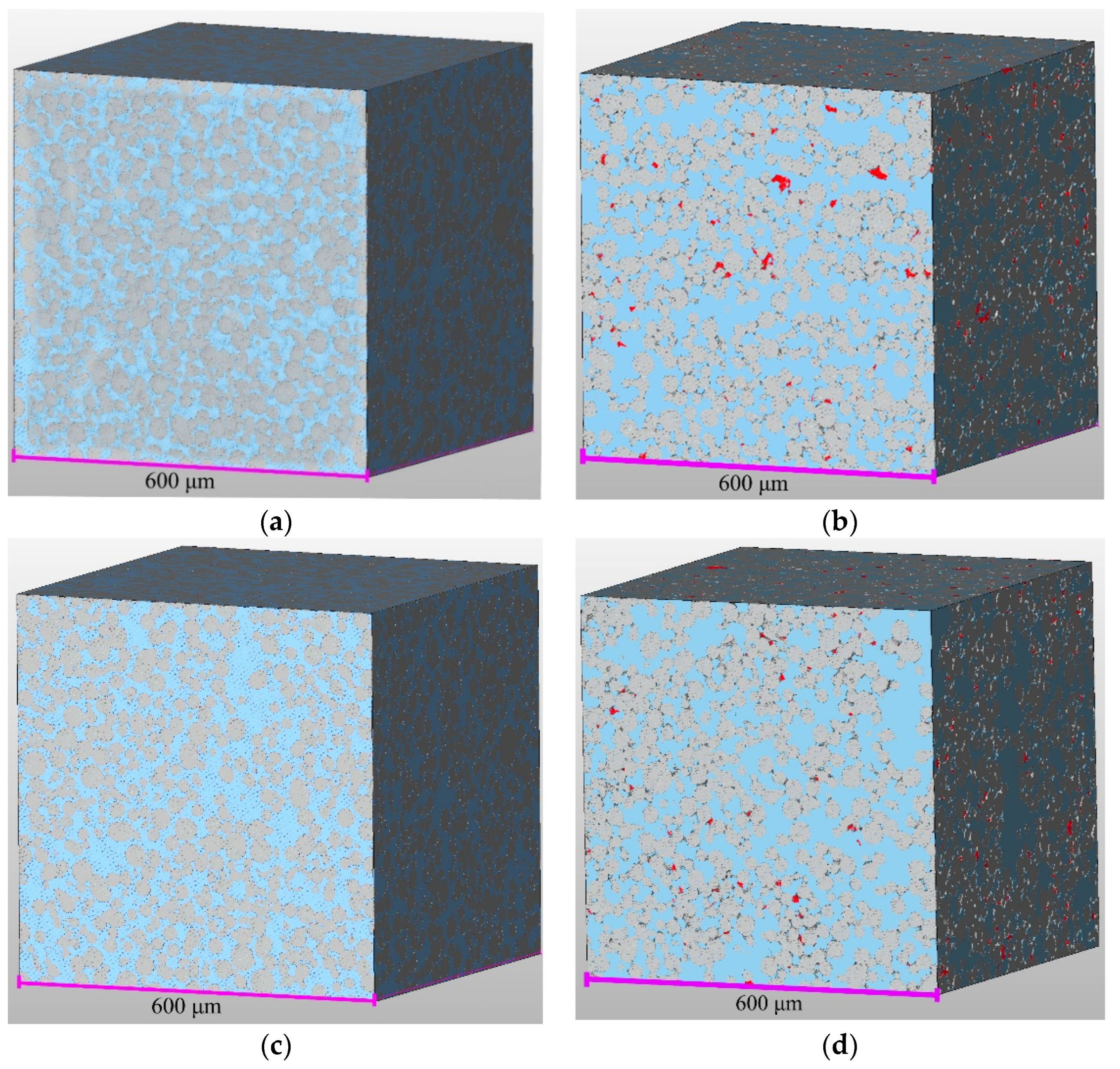
Figure 3.
xCT images of green models, where Inconel 718 matrix is highlighted in gray, TiC particles are in red and pores are in blue: INC (a), INC-m (b), INC-n (c) and INC-mn (d).
Figure 4.
Result of the DSC analysis of INC.
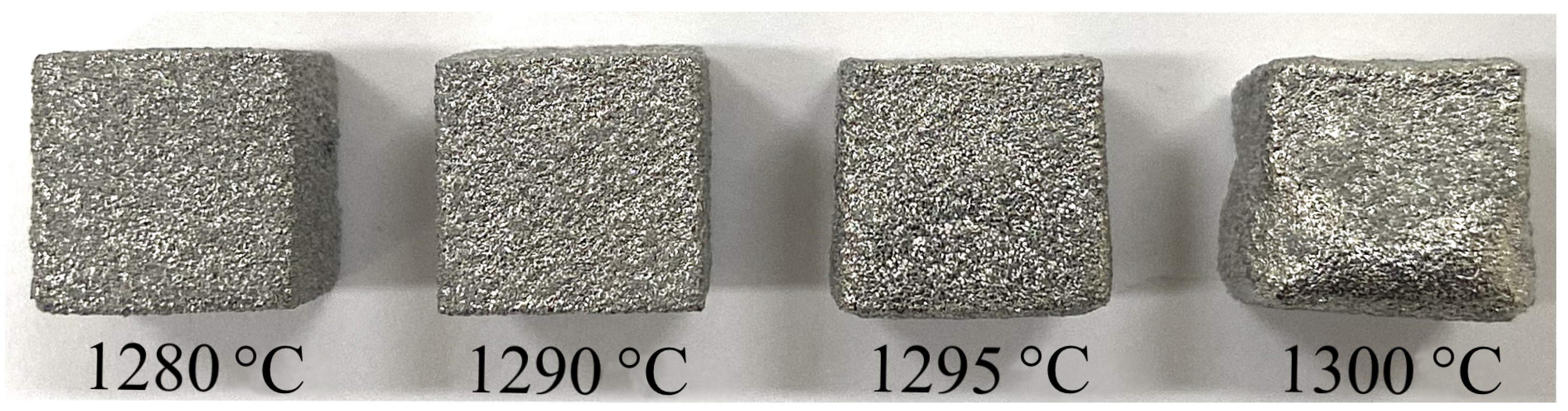
Figure 5.
Image of INC samples sintered at different temperatures.
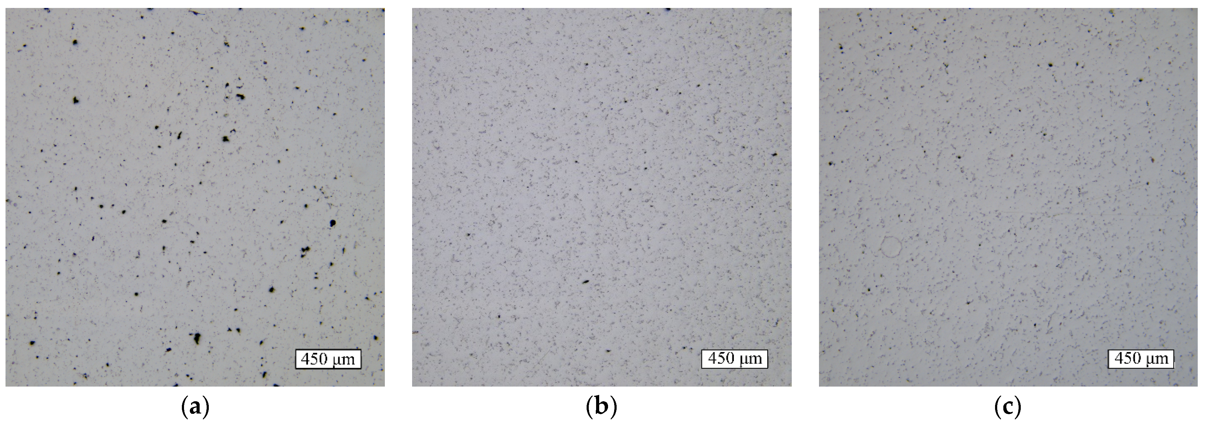
Figure 6.
Images of cross sections with internal distribution of porosity in INC samples sintered at various temperatures: 1280 °C (a), 1290 °C (b) and 1295 °C (c).
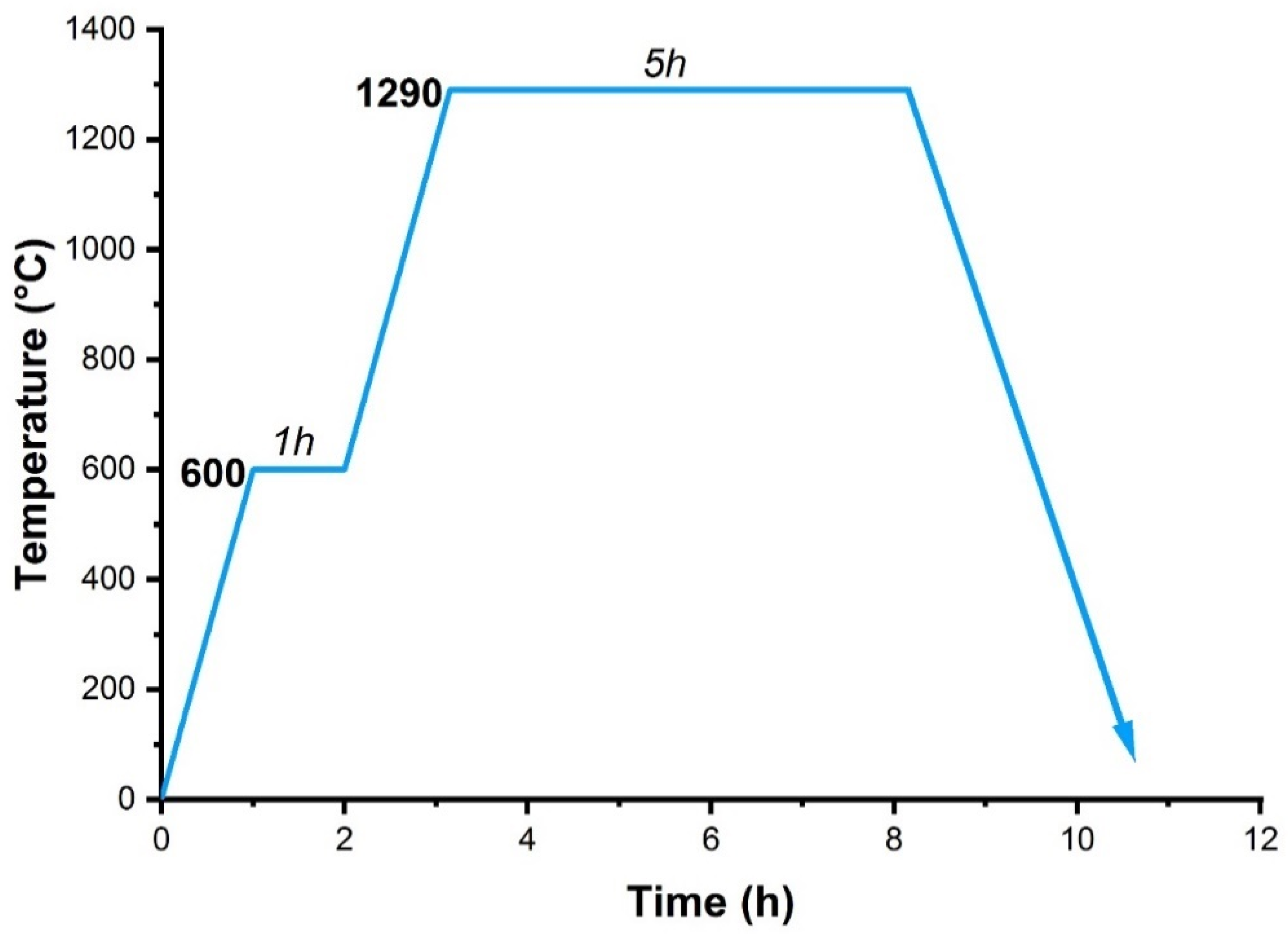
Figure 7.
Thermogram of the sintering process.
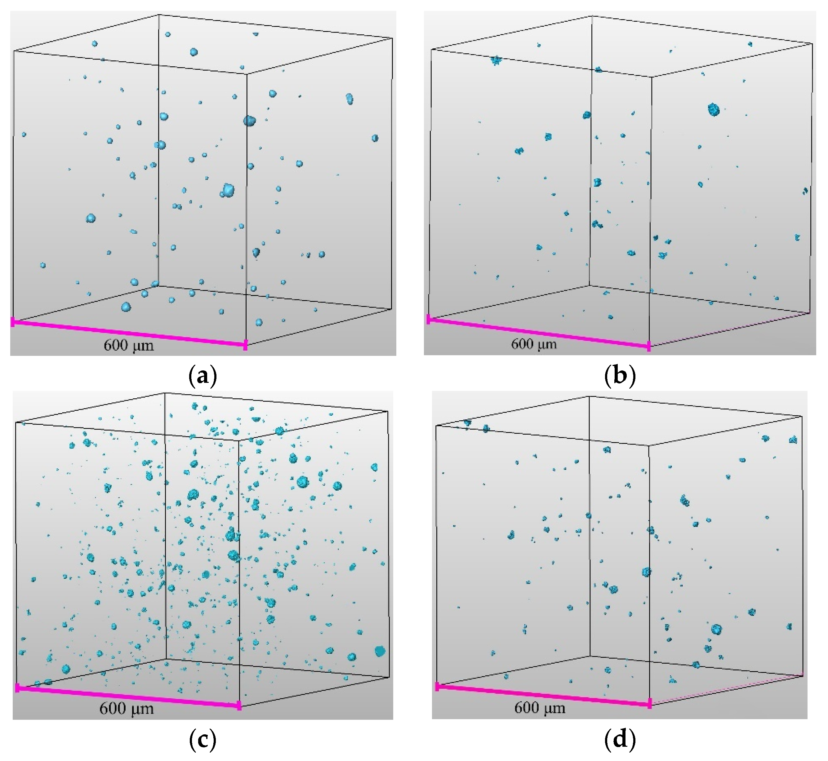
Figure 8.
xCT images of pore distribution (highlighted in blue) in sintered samples: INC (a), INC-m (b), INC-n (c) and INC-mn (d).
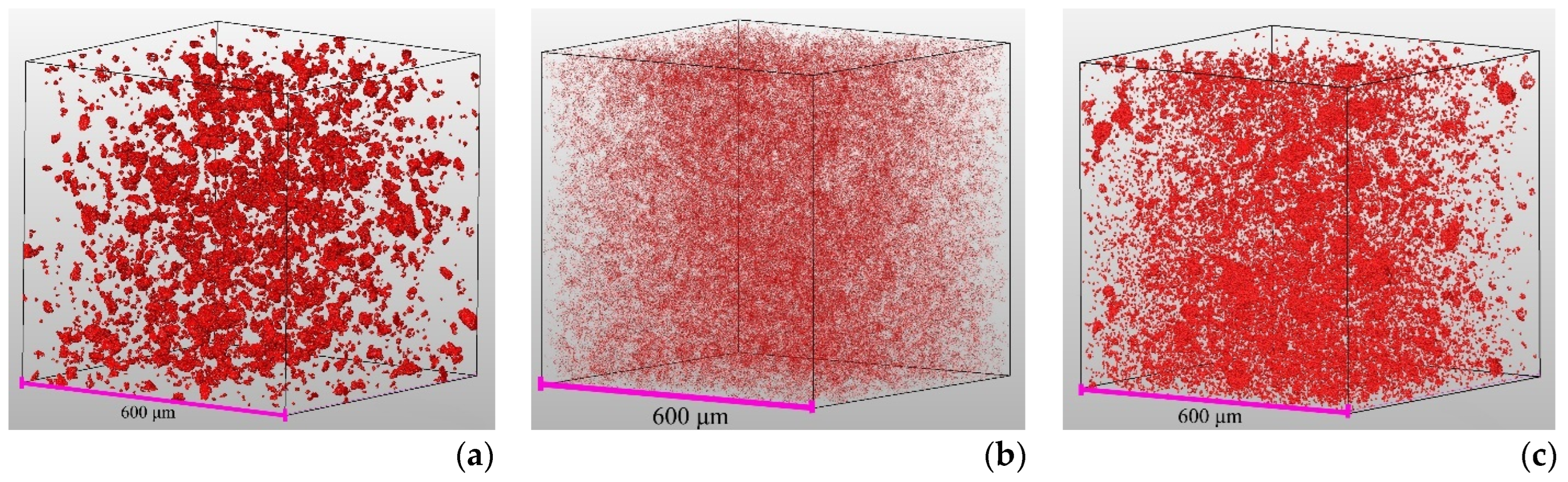
Figure 9.
xCT images of TiC particle distribution (highlighted in red) in sintered samples: INC-m (a), INC-n (b) and INC-mn (c).
Figure 10.
xCT images of pore distribution (highlighted in blue) in samples after HIP: INC (a), INC-m (b), INC-n (c) and INC-mn (d).
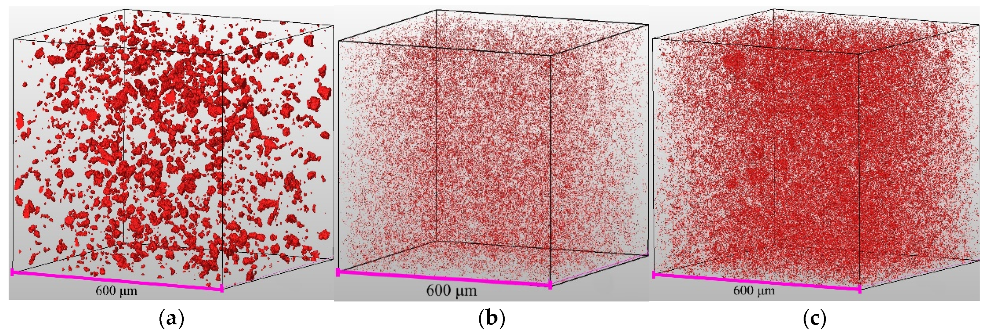
Figure 11.
xCT images of TiC particle distribution (highlighted in red) in samples after HIP: INC-m (a), INC-n (b) and INC-mn (c).
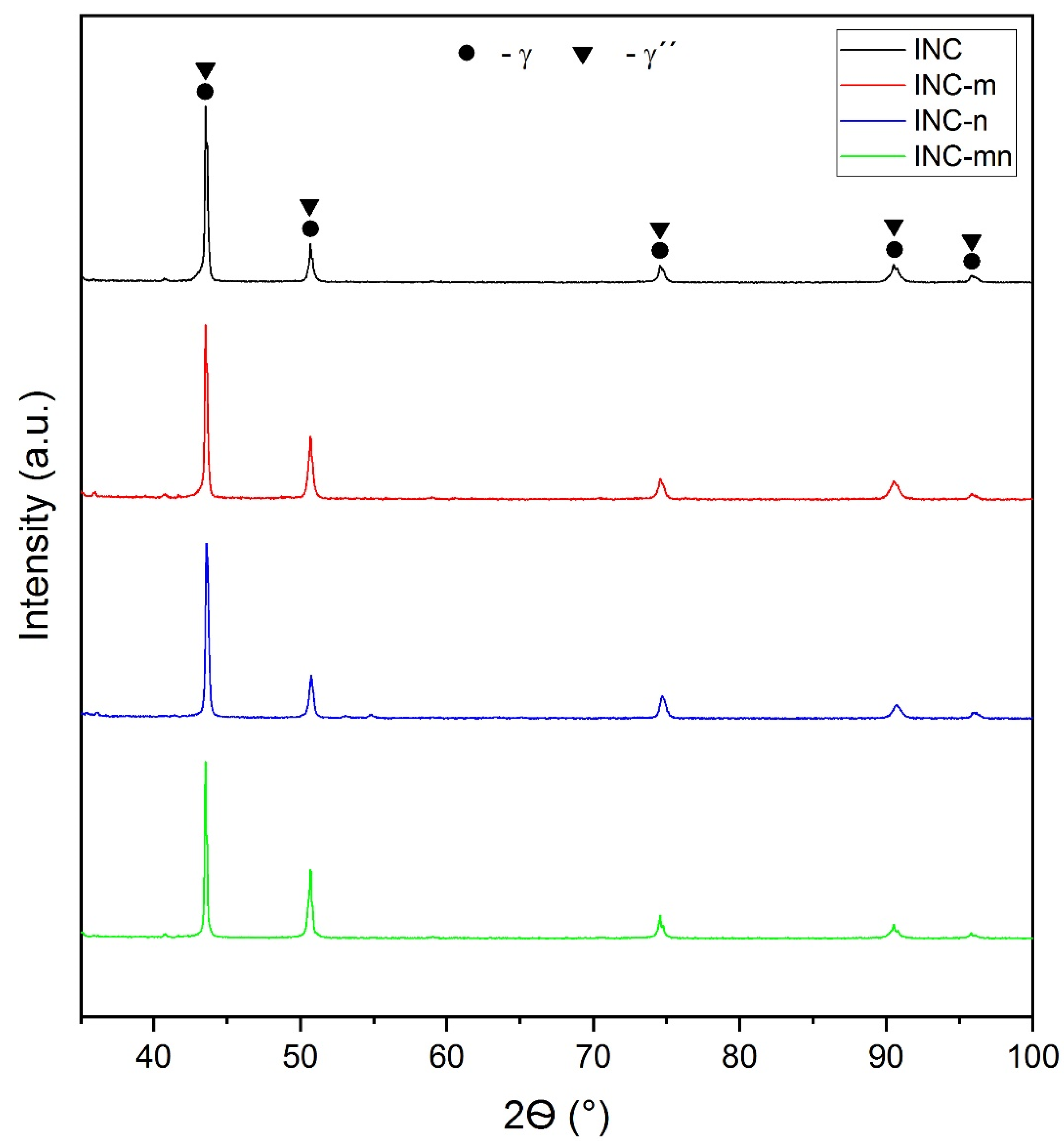
Figure 12.
XRD of the samples after the HIP and HT.
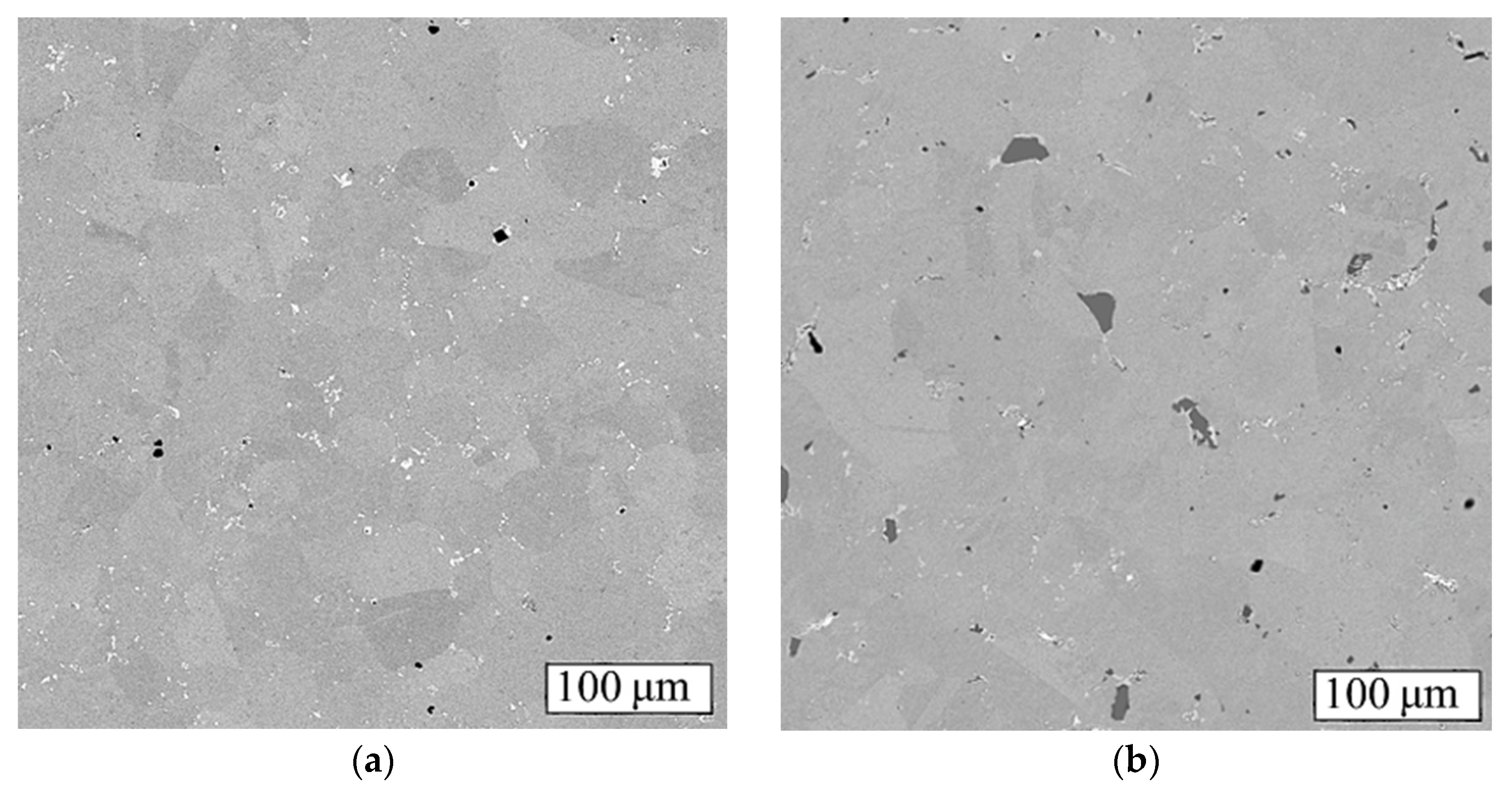
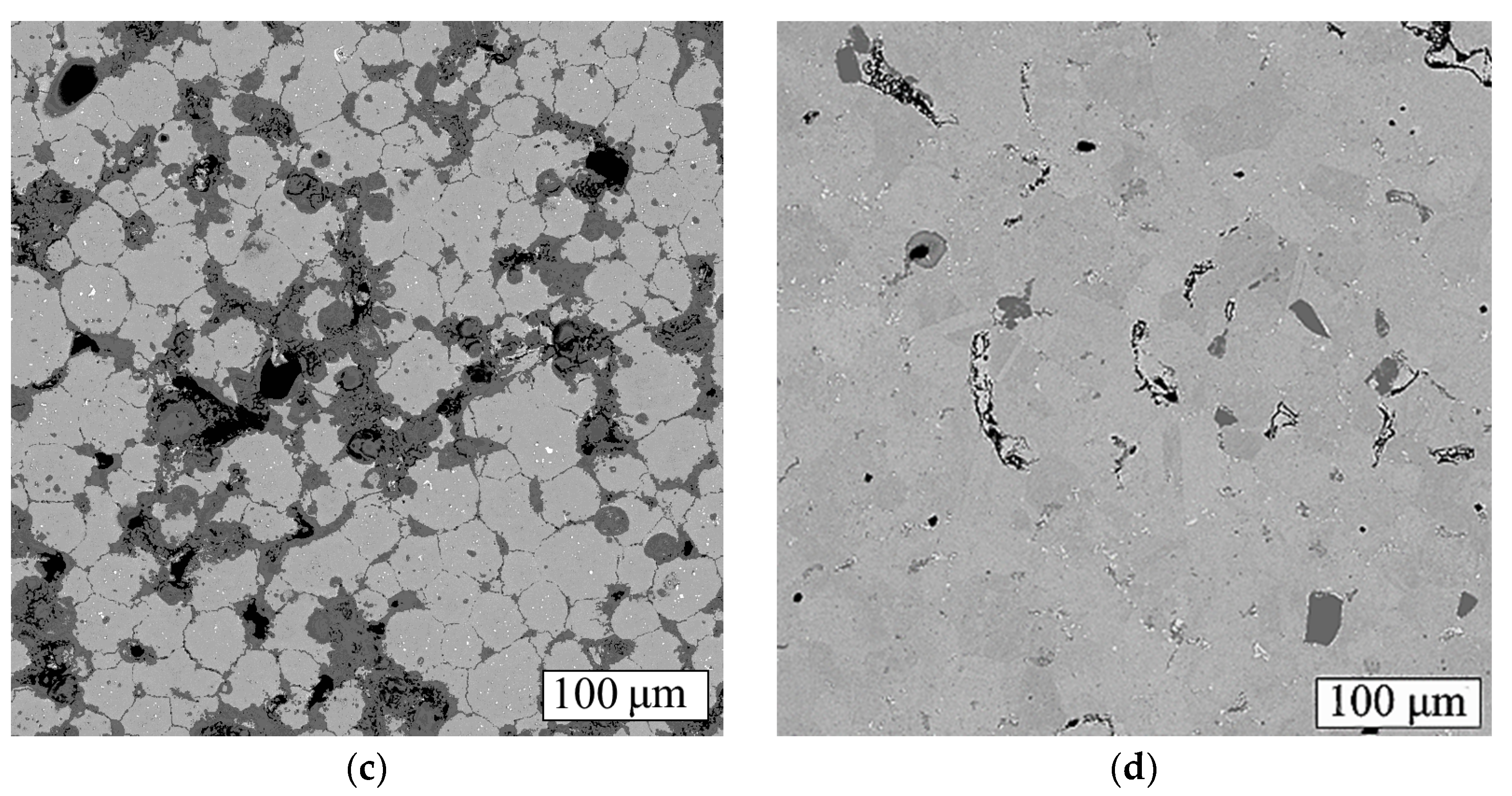
Figure 13.
SEM images (BSE) of samples after HIP and HT: INC (a), INC-m (b), INC-n (c) and INC-mn (d). The black areas are pores and the dark gray areas are clusters of nano-sized TiC and micron-sized TiC particles.
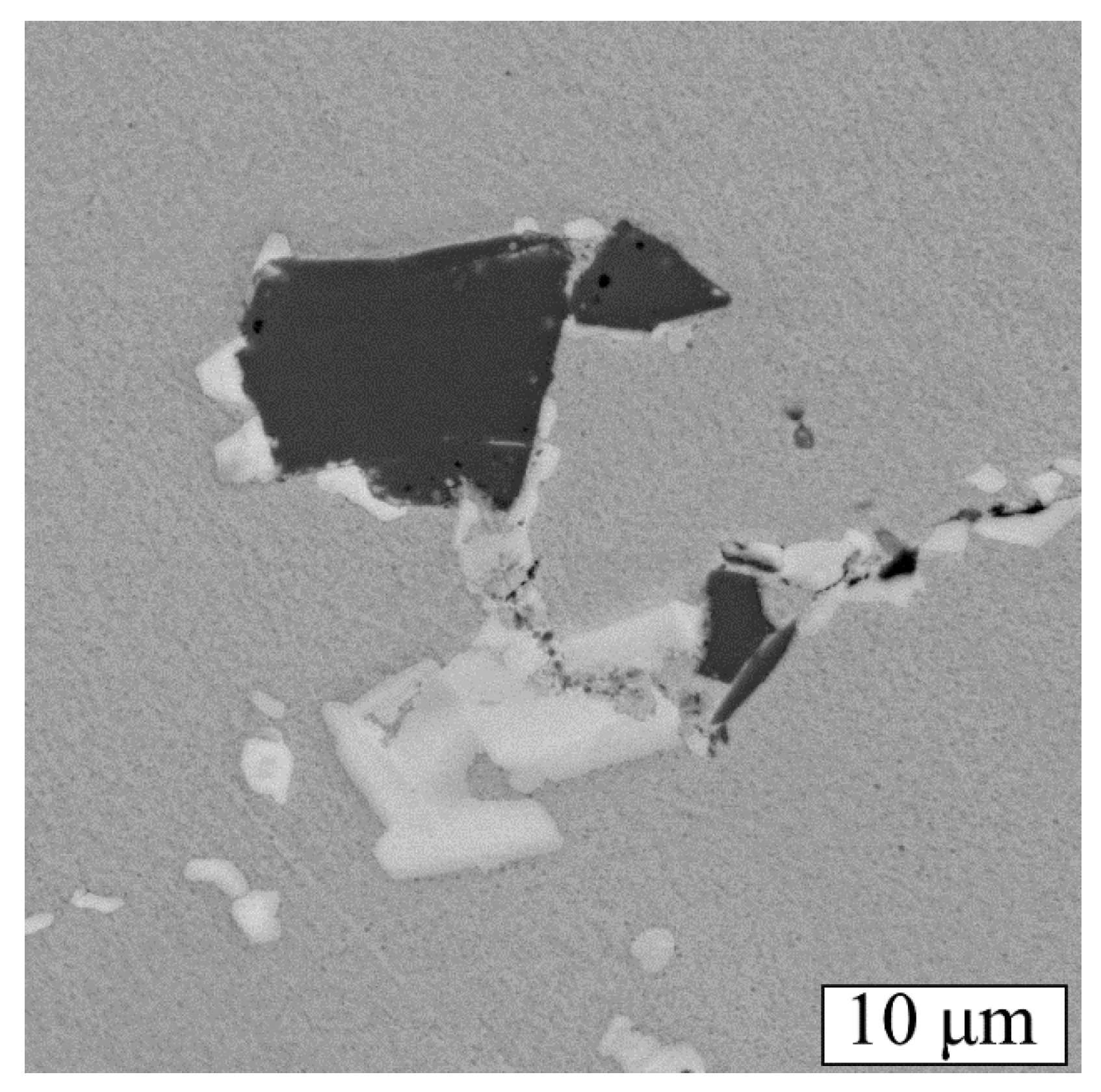
Figure 14.
Precipitated carbide phase in the vicinity of micron-sized TiC particles.
Table 1.
The chemical composition of Inconel 718 powder data from [
31].
| Elements | Cr | Fe | Nb/Ta | Mo | Ti | Al | Ni |
|---|
| wt% | 18 | 18 | 5 | 3 | 1 | 0.6 | Bal. |
Table 2.
Designations for the investigated powders.
| Powder | Designation |
|---|
| Inconel 718 | INC |
| Inconel 718 + 1% micron-sized TiC | INC-m |
| Inconel 718 + 1% nano-sized TiC | INC-n |
| Inconel 718 + 0.5% micron-sized TiC + 0.5% nano-sized TiC | INC-mn |
Table 3.
Technological properties of the powders.
| Powder | Flow Rate, s/50 g | Apparent Density, g/cm3 |
|---|
| INC | 11.9 ± 0.1 | 4.40 ± 0.07 |
| INC-m | 13.6 ± 0.4 | 4.23 ± 0.05 |
| INC-n | 12.4 ± 0.2 | 4.35 ± 0.06 |
| INC-mn | 12.9 ± 0.3 | 4.31 ± 0.08 |
Table 4.
Particle size distribution of the powders.
| Powder | d10, μm | d50, μm | d90, μm |
|---|
| INC | 21.4 ± 1.1 | 38.9 ± 1.1 | 66.4 ± 1.1 |
| INC-m | 21.6 ± 0.9 | 39.8 ± 0.9 | 68.3 ± 0.9 |
| INC-n | 22.7 ± 1.2 | 39.5 ± 1.2 | 69.4 ± 1.2 |
| INC-mn | 22.2 ± 1.0 | 38.5 ± 1.0 | 67.2 ± 1.0 |
Table 5.
Parameters of the printing process.
| Parameter | Value |
|---|
| Layer thickness, mm | 0.1 |
| Saturation (%) | 60 |
| Bed Temp (°C) | 27 |
| Dry (s) | 24 |
Table 6.
Density values of green models and Inconel 718 superalloy.
| Material | Density, g/cm3 |
|---|
| INC | 4.67 ± 0.12 |
| INC-m | 4.39 ± 0.07 |
| INC-n | 4.65 ± 0.10 |
| INC-mn | 4.51 ± 0.10 |
| Inconel 718 | 8.19 |
Table 7.
Density of INC samples sintered at different temperatures.
| Sintering Temperature, °C | Density, g/cm3 |
|---|
| 1280 | 7.61 ± 0.07 |
| 1290 | 7.96 ± 0.08 |
| 1295 | 8.04 ± 0.09 |
Table 8.
Density of samples after sintering and HIP.
| Sample | Density, g/cm3 |
|---|
| After Sintering | After HIP |
|---|
| INC | 7.96 ± 0.08 | 8.17 ± 0.09 |
| INC-m | 7.94 ± 0.09 | 8.09 ± 0.08 |
| INC-n | 7.16 ± 0.06 | 7.21 ± 0.07 |
| INC-mn | 7.51 ± 0.07 | 7.58 ± 0.06 |
Table 9.
Hardness of samples (HV10).
| Sample | After Sintering | After HIP and HT |
|---|
| INC | 229 ± 7 | 411 ± 12 |
| INC-m | 251 ± 8 | 425 ± 13 |
| INC-n | 140 ± 4 | 216 ± 6 |
| INC-mn | 148 ± 5 | 364 ± 10 |
Table 10.
Tensile mechanical properties at different temperatures.
| Sample | Test Temperature, °C | YS, MPa | UTS, MPa | δ, % |
|---|
| INC | 25 | 836 ± 8 | 1014 ± 10 | 4.49 ± 0.05 |
| INC-m | 25 | 975± 10 | 1160 ± 12 | 13.01 ± 0.13 |
| INC-n | 25 | 268 ± 3 | 308 ± 3 | 0.53 ± 0.01 |
| INC-mn | 25 | 587 ± 6 | 695 ± 6 | 1.65 ± 0.02 |
| INC | 700 | 669 ± 7 | 715 ± 7 | 1.45 ± 0.01 |
| INC-m | 700 | 782 ± 9 | 845 ± 8 | 4.17 ±0.08 |
| INC-n | 700 | - | 203 ± 2 | 0.00 |
| INC-mn | 700 | - | 356 ± 4 | 0.00 |
| Disclaimer/Publisher’s Note: The statements, opinions and data contained in all publications are solely those of the individual author(s) and contributor(s) and not of MDPI and/or the editor(s). MDPI and/or the editor(s) disclaim responsibility for any injury to people or property resulting from any ideas, methods, instructions or products referred to in the content. |
© 2023 by the authors. Licensee MDPI, Basel, Switzerland. This article is an open access article distributed under the terms and conditions of the Creative Commons Attribution (CC BY) license (https://creativecommons.org/licenses/by/4.0/).


