Article

Microstructure Refinement and Work-Hardening Behaviors of NiAl Alloy Prepared by Combustion Synthesis and Hot Pressing Technique

1
Key Laboratory of Automobile Materials, Ministry of Education and Department of Materials Science and Engineering, Jilin University, Changchun 130025, China
2
School of Mechanical and Aerospace Engineering, Jilin University, Renmin Street No. 5988, Changchun 130025, China
3
Kocel Intelligent Machinery Limited, Yinchuan 750021, China
*
Authors to whom correspondence should be addressed.
Metals 2023, 13(6), 1143; https://doi.org/10.3390/met13061143
Submission received: 16 May 2023 / Revised: 5 June 2023 / Accepted: 15 June 2023 / Published: 19 June 2023
(This article belongs to the Special Issue Advanced Intermetallic Alloys and Intermetallics)

Abstract

:
Most methods used to synthesize and prepare NiAl intermetallics and their alloys have the disadvantages of complexity and high cost. In this paper, the NiAl alloy was prepared by a Combustion Synthesis and Hot Pressing (CSHP) technique under rapid solidification. The grain size of the NiAl alloy is significantly refined to 60–80 μm, which reduces the stress concentration during deformation and improves the fracture strength and fracture hardness. Moreover, the large internal stress and greater amount of dislocations in the as-cast microstructure are produced by their formation under pressure due to the fast cooling rate in the solidification process. The high dislocation density strengthens the NiAl alloy, giving it higher strength, hardness, and work-hardening ability. The high compression properties are also present in the NiAl intermetallics at room temperature, in which the fracture strength is around 1005 MPa and the fracture strain reaches 21.6%. The compressive fracture strength at room temperature is higher than that of the pure NiAl alloy prepared by the Hot-Pressing-Aided Exothermic Synthesis (HPES, about 632 MPa), while it is slightly lower than that of pure NiAl alloy treated by HPES and Hot Isostatic Pressing (HIP, 1050 MPa). The fracture strain is significantly higher than that of the NiAl alloy prepared by other methods. This study can provide guidance for the successful preparation of the NiAl alloy with high strength and toughness.

1. Introduction

NiAl intermetallic compounds (NiAl), as advanced high-temperature structural materials, are expected to play an important role in realizing the aspirations related to the next-generation aerospace propulsion devices because of their excellent oxidation resistance, good thermal conductivity, high Young’s modulus (240 GPa), and high melting point (1638 °C) [1,2,3,4,5,6]; however, its poor toughness and ductility at room temperature [7,8,9,10], as well as the low strength at high temperatures hamper its further application. The development of NiAl matrix composites has been proven to be a promising way to overcome these shortcomings. In recent decades, considerable efforts have been made to produce NiAl matrix composites reinforced with ceramic particles and NiAl alloys incorporating alloying elements [11,12,13,14,15].
At present, high-temperature melting and arc melting are widely used to synthesize and prepare NiAl intermetallic compounds and their alloys; however, the preparation of the NiAl alloy by melting method usually has the problem of composition segregation and coarse grain [16]. Therefore, powder metallurgy methods, including Hot-Pressing-Aided Exothermic Synthesis (HPES), Hot Isostatic Pressing (HIP), and Self-propagating High-temperature Synthesis (SHS) have been developed. HPES is the rapid heating of the pressed billet to a temperature above the melting point of the metal matrix to cause it to react [11,17,18]. HIP is the sintering and densification of the alloy under the action of high temperature and pressure of the press billet [19,20,21]. SHS refers to the formation of an alloy in an instant by using the self-conducting effect of the heat of reaction of a substance [22,23]. For example, Guo et al. [11] prepared NiAl alloys by HPES and they found that the ultimate compressive strength is 632 MPa and the fracture strain is 4%. In addition, HIP and Heat Treatment (HT) had no significant effect on the Vickers hardness of NiAl intermetallics. Guo et al. and Xing et al. [17,18] prepared NiAl alloys by HPES and they found that the hardness of NiAl is about 314 HV. Xing et al. [18] introduced TiC particles into the NiAl alloy matrix by HPE. They reported that the ultimate strength of NiAl matrix composite containing 20 vol.% TiC is 1479 MPa and its fracture strain is 14.5%. The strength of the NiAl matrix composites containing ceramic particles prepared by HPES technology is obviously improved, but the increase in fracture strain is not significant. Shekari et al. [24] successfully prepared the NiAl alloy using the SHS method and investigated the effect of particle size on the formation of the NiAl alloy. XRD and SEM-EDS analysis showed that the Ni + Al powder mixture was completely transformed into a uniform NiAl alloy. In addition, even with very coarse nickel particles, the combustion front does not lose stability. But the above method has the problem of high energy consumption and high porosity. Sheng et al. and Zhou et al. [25,26] reported that the ductility and hardness of NiAl alloys containing Au or Ag had a slightly increase compared with that of the alloy without the addition of alloying elements. Although alloying elements can somewhat enhance mechanical properties, their expensive cost will limit their widespread use. To sum up, it is necessary for us to find an economical, applicable, and convenient method for preparing the NiAl alloy with good strength and ductility.
In this study, the NiAl alloy was prepared using Combustion Synthesis and Hot Pressing (CSHP) at high temperature, which makes it possible to quickly and effectively prepare NiAl alloys at a low cost and with very little energy. The microstructure, compression properties and work-hardening ability of NiAl alloy are investigated. The effects of different strain rates and loading modes on mechanical properties and work-hardening effect are revealed. It is expected that this study can provide a new preparation idea for the preparation of the NiAl alloy with excellent mechanical properties.

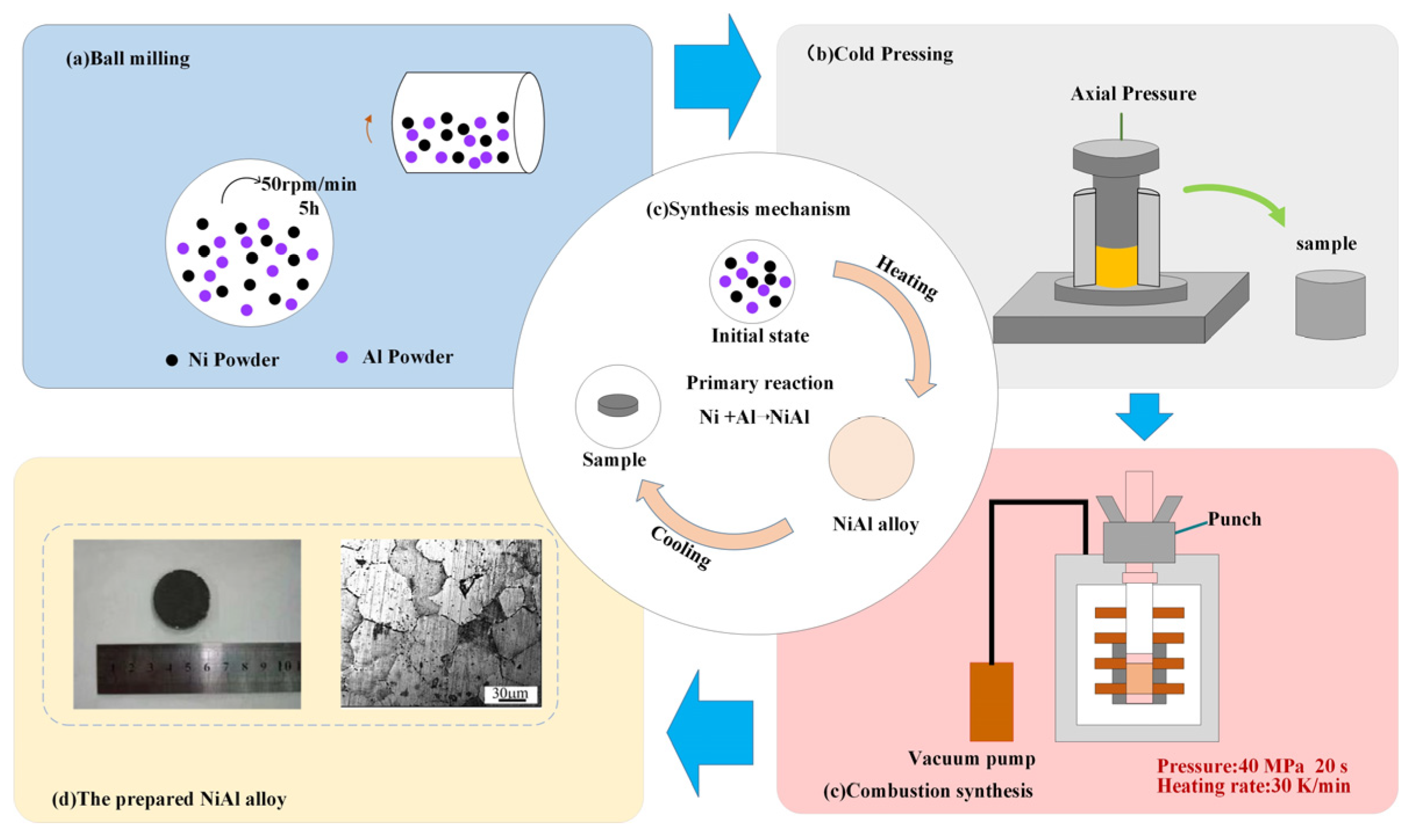
2. Materials and Methods

The raw materials used here are commercially available Ni (45 μ m, 99.5% purity) and Al (29 μ m, 99.0% purity) powders. Ni powder accounted for 68.5 wt.% and Al powder accounted for 31.5 wt.%. They are thoroughly mixed in a ball mill for 6 h, and the ball-milling speed was set to 60 rpm. Then, the powder mixture is pressed into a cylindrical with a theoretical density of 65 ± 2% at room temperature using a stainless-steel mold (28 × Ø35 mm). NiAl was prepared in a vacuum hot-pressing furnace at a heating rate of 30 K/min. As the temperature increases, Ni and Al react in situ to form NiAl alloys and release large amounts of heat, thus further promoting NiAl formation and temperature increase. When the temperature reaches about 400 °C, the reaction of the combustion synthesis reaction system is ignited, it means that reaction between Ni and Al is activated, the temperature of the system rises sharply [24]. Then, an axial stress of 40 MPa is applied and hold it for about 20 s, then cool it to room temperature in the furnace. The preparation process of NiAl is shown in (Figure 1).
The phases of sample were determined using X-ray diffraction (XRD, D/max2500PC Rigaku, Tokyo, Japan). The dislocation density before and after compression was analyzed by XRD line profile analysis method. The dislocation density (ρ) can be calculated by the following formula [27].
ρ = 2 / 3 ( η 2 ) 1 2 / d c × B
where dc is the average grain size, B is Burgers vector (B = 0.286 nm) and ( η 2 ) 1 2 is microstrain. Williamson–Hall method is used for calculating ρ. The relationship between the Bragg diffraction angle (θ) and full width at half maximum (FWHM) intensity was expressed as [27]
FWHM × cos θ = η · 2 sin θ + 0.9 λ / d c
where λ is the Cu-Kα radiation wavelength (λ = 0.154 nm). According to Equations (1) and (2), the dislocation density can be obtained.
The microstructure, element distribution and phase composition were analyzed by SEM (SEM, Evo18, Carl Zeiss, Oberkochen, Germany) and HRTEM (HRTEM, JEM-2100F, JEOL, Tokyo, Japan).
The compressed sample with a diameter of 2 mm and height of 4 mm is taken out from the central area of the sample of NiAl for a room temperature compression test. Its cylindrical face and two end faces are polished in ensuring that the two end faces are parallel to each other and perpendicular to the height direction. The compression properties of the samples are tested by servo hydraulic material testing system (MTS, MTS810, Eden Prairie, MN, USA) at room temperature. Unidirectional axial compression tests were performed on the compressed specimens with a length to diameter ratio of 2:1. The ET-320 density tester is used to measure the density of the NiAl alloy, and the Archimedes drainage method provides the basis for the test.

3. Results and Discussion

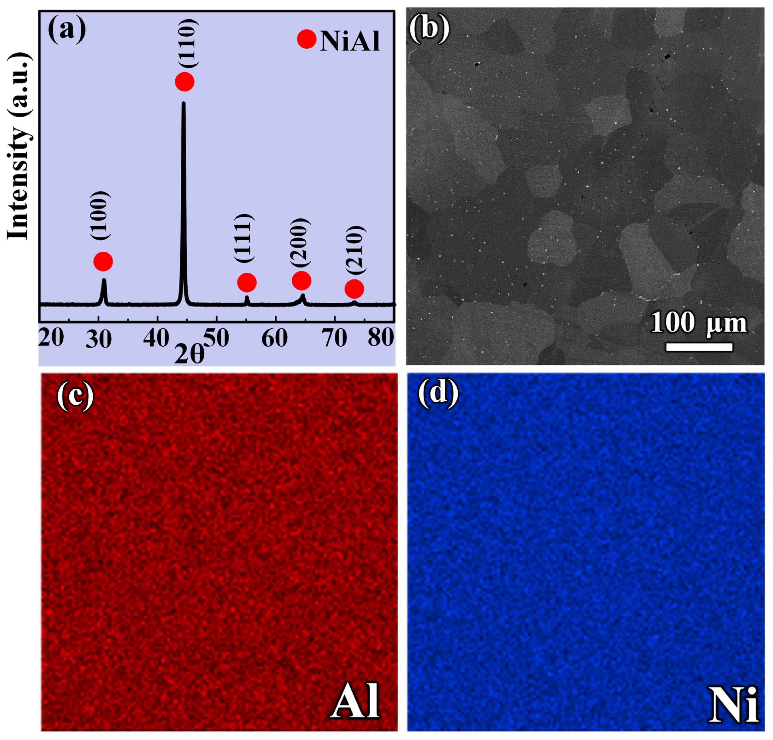
3.1. Phase Composition and Microstructure Analysis

The specimens selected for this part of the characterization are taken from the center of the prepared cylindrical NiAl alloy and the characterization results are constant over the cross section. Figure 2a shows the XRD pattern of the NiAl fabricated by CSHP. As can be seen, a pure NiAl alloy is formed by the combustion synthesis reaction between Ni powder and Al powder. The generated NiAl alloy has a body-centered cubic structure with a lattice constant (a) of 0.2887 nm, and belongs to the space group of pm-3 m. Figure 2b shows the scanning electron microscope (SEM) image of prepared NiAl alloy. As indicated, the grains size of NiAl intermetallics are between 60 μm and 80 μm, which are smaller than that of the pure NiAl alloy reported from Refs. [28,29]. Moreover, no porosity was observed in the SEM image, which indicates that the prepared NiAl alloy is dense. In order to know more accurately the densification of the prepared NiAl alloy, its density was accurately measured. The density of the prepared NiAl alloy was 3.79 g/cm3, with a densification of 98.2%. Figure 2c,d shows the elements distribution of Al and Ni elements in the prepared NiAl alloy, respectively. It can be seen that the distribution of Al and Ni elements are uniform. It indicates that the reaction of Ni and Al is complete. The XRD diffraction analysis also indicates that the reaction of Ni and Al is complete and that a pure NiAl alloy compound is obtained.
In general, homogeneous and heterogeneous nucleation are two methods for nucleation during the solidification of liquid metal. Assuming that a given volume of liquid metal produces n atoms at a certain degree of undercooling and the crystal nucleus is spherical, the Gibbs free energy of the system can be calculated by the following Equation,
G a v e r a g e = 4 3 π r a v e r a g e 3 G V n + 4 π r a v e r a g e 2 σ C L n
where r is the radius of the spherical core, ΔGv is the change in free energy per unit volume in the liquid metal during solidification, n is the number of atoms, and σCL is the interfacial tension between the liquid phase and the crystal nucleus. According to Equation (3), the nucleation process can take place because the free energy of the system is reduced only when r reaches a certain value r*average (the critical size of the crystal nucleus). That is to say, the atomic groups can become the core of stability only when r > r a v e r a g e * . In order to determine r a v e r a g e * , take the derivative of Formula (3) and make the derivative zero, d G a v e r a g e d r = 0
4 π r a v e r a g e * 2 n G V + 8 π r a v e r a g e * n σ C L = 0
r a v e r a g e * = 2 σ C L G V
Substitute G = L T T m into Formula (5) to obtain
r a v e r a g e * = 2 σ C L T m L Δ T
where Tm is the melting point of metal, ΔT is the amount of subcooling, and L is the latent heat of crystallization. Therefore, the greater the degree of supercooling, the more favorable the nucleation. In order to study the supercooling degree of the NiAl alloy prepared by CSHP and its effect on grain size, we studied the temperature change in the process of NiAl alloy synthesis and cooling.
Figure 3a,b shows the phase diagram and the solidification cooling curve of the NiAl alloy, respectively. At low temperatures, some Ni and Al solid solution phases are formed. At about 400 °C, these solid solution phases melted, which began to promote the reaction of Ni and Al to form NiAl and release a lot of heat, and the temperature rose sharply to 2383 °C [24]. As indicated, Ni and Al have completely melted at 2383 °C. Figure 3c proves that the combustion synthesis happens instantaneously. When the temperature rises sharply, an axial pressure is applied to the NiAl alloy. At this time, due to the very low temperature of the upper and lower indenter, the mold and the surrounding environment, compared to the sample, a larger degree of supercooling (ΔT) is caused. According to the inversely proportional relationship between the critical size of the crystal nucleus and the degree of undercooling (Equation (6)), the nucleation is more likely to occur when the degree of supercooling is larger, resulting in an increase in nucleation site density. This may be the reason why the grains of the NiAl alloys are clearly refined.
Figure 4a shows the TEM images of NiAl intermetallics prepared by CSHP. Figure 4b is the selected area electron diffraction (SAED) analysis of region A, which can be used to further determine the matrix phase. The analysis result shows that the NiAl phases are formed in region A, it once again proves that the NiAl alloy has been successfully prepared by CSHP. A high-resolution TEM (HRTEM) of region B in Figure 4a is shown in Figure 4c. A high-resolution tissue image of the region C in Figure 4c is shown in Figure 4d. Figure 4e,f is inverse Fast Fourier Transformation (IFFT) images of Figure 4d, and the illustration is a Fast Fourier Transformation (FFT) image. The symbol “T” in figure represents the dislocations. Figure 4e,f shows that the high dislocation density in the NiAl matrix and serious distortion in the crystal lattice are generated. This is because the NiAl alloy has a very large degree of supercooling during the non-equilibrium solidification. Therefore, a large internal stress results in the formation of more dislocations in the alloy, which plays a positive role in enhancing the mechanical properties of the NiAl alloy.

3.2. Effect of CSHP Process on Mechanical Properties of NiAl

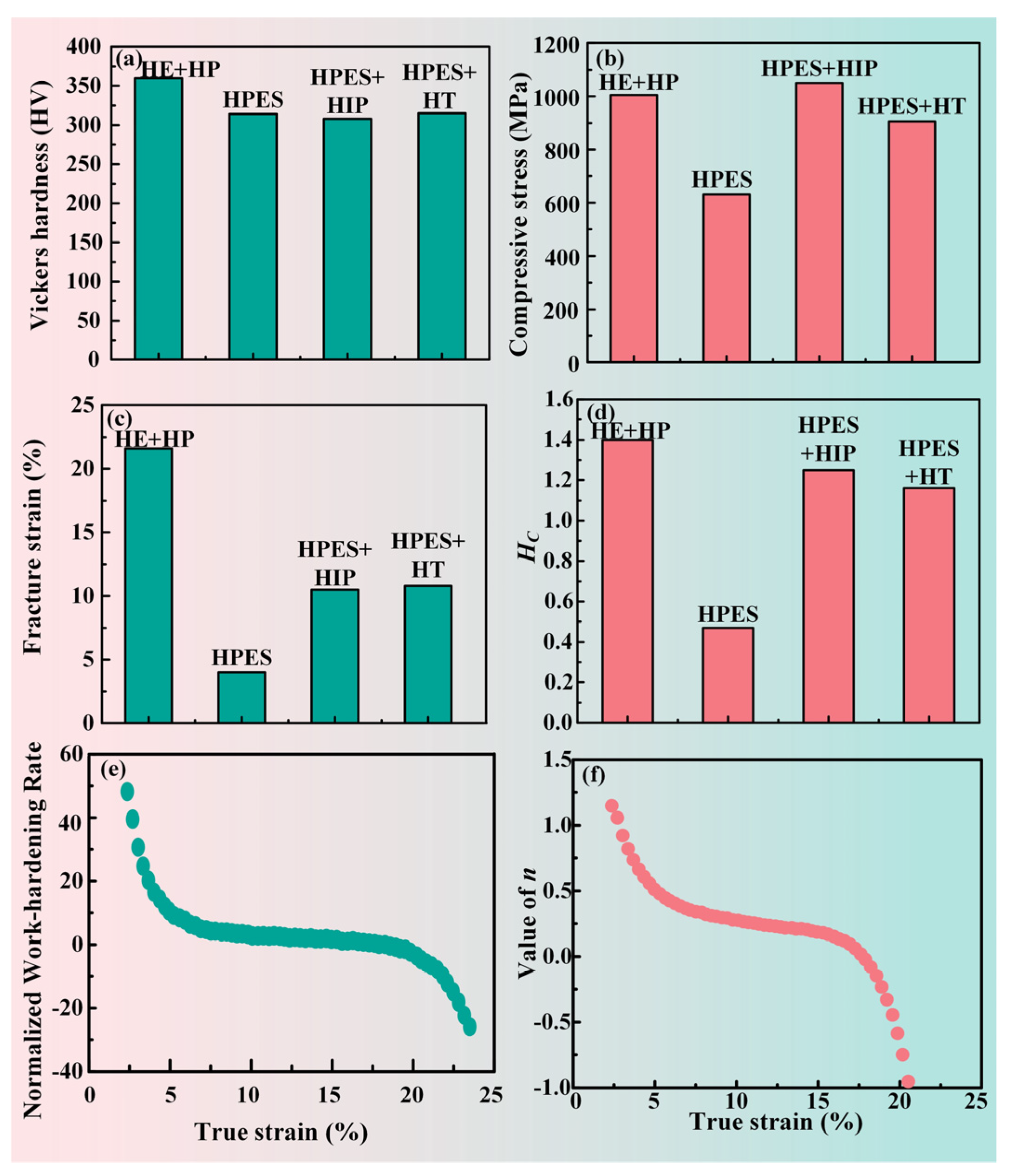
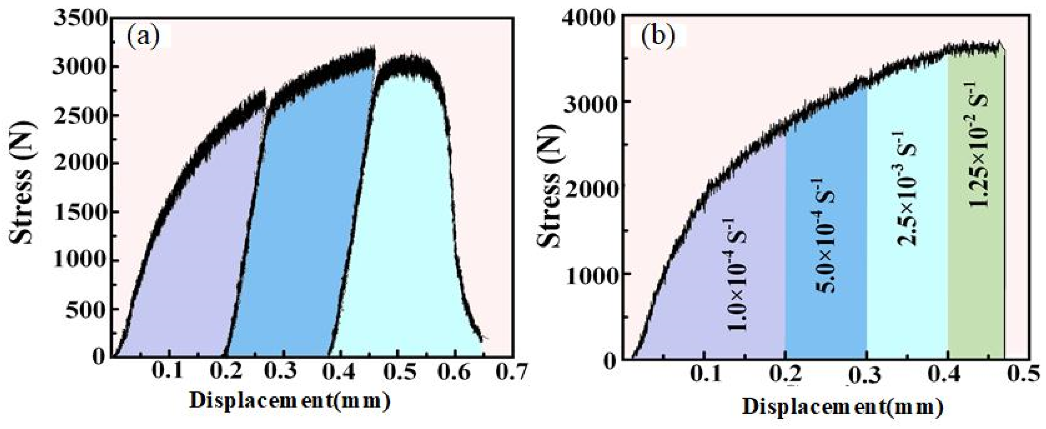
3.2.1. Room Temperature Compression Performance

Figure 5 shows the mechanical properties of the NiAl alloy prepared by CSHP method and the corresponding values are given in Table 1. The hardness (360 HV) of NiAl alloy prepared by CSHP is greater than that of the NiAl alloy prepared by other methods. The room temperature compression fracture strength (about 1005 MPa) is higher than that of the pure NiAl alloy prepared via the HPES method (about 632 MPa), but is slightly lower than that of the pure NiAl alloy treated by HPES and HIP (1050 MPa). The fracture strain of the NiAl alloy is significantly higher than that of the NiAl alloy prepared by other methods, reaching 21.6%. The fracture strains of NiAl alloy treated by other methods are between 4% and 10%. The properties of NiAl alloy prepared by CSHP are similar to those of NiAl alloys prepared by hot isostatic pressing requiring high-pressure equipment. Therefore, the in situ hot pressing, combined with combustion synthesis, is an economical method to prepare a high-performance NiAl alloy.

3.2.2. Work Hardening Ability

In order to evaluate the work-hardening ability of NiAl alloys, Hc was calculated as
H c = σ t r u e f σ t r u e y / σ t r u e y = σ t r u e f / σ t r u e y 1
where σ t r u e f is the true fracture strength and σ t r u e y is the true yield strength. Figure 5d gives a comparative diagram of the work hardening ability of NiAl alloys prepared by different methods. As indicated, the pure NiAl alloy prepared by CSHP has a higher work hardening ability than that of NiAl alloys prepared by other methods.
To estimate the effect of the work hardening on the mechanical properties of the NiAl alloy, the standardized work hardening rate (Θ) is introduced.
Θ = d σ t r u e / d ε t r u e / σ t r u e
where σtrue is real stress and ε t r u e is real strain [30,31,32]. Figure 5e gives the hardening rate–strain curve of pure NiAl alloys prepared by CSHP. The real strain increases while the normalized work-hardening rate decreases. The reduction in the hardening rate of the NiAl alloy prepared by CSHP is relatively low, indicating that the Θ value is higher under the condition of higher strain. Therefore, the NiAl intermetallics prepared by CSHP have a strong work-hardening ability.
In order to further investigate the work hardening capacity of NiAl alloys prepared by CSHP, we used the following Hollomon formula to fit the unidirectional compression curve of the plastic zone.
σ t r u e = K ε t r u e n
where K and n are the strength and work hardening coefficients, respectively [33,34]. The relationship curves between work hardening coefficients (n) and real strain are given in Figure 5f. The n value of the NiAl alloy prepared in this work decreases gradually with the increase in real strain, but the n value of the NiAl alloy prepared by combustion synthesis method still has a positive n value under a higher real strain.
In order to further study the compression properties of NiAl alloy at RT, we investigated the effects of different loading modes on the compression performance of NiAl alloy. Figure 6a shows the stress-displacement curves of NiAl intermetallics under loading, unloading, and cyclic stress compression modes. As indicated, the loading modes have no significant effect on the compression performance of NiAl alloy. In addition, the compression properties of the pure NiAl alloy prepared by CSHP also has no significant dependence on deformation parameters.
Figure 6b shows the variation of room temperature compression engineering strain–stress curve with the strain rate for NiAl intermetallic compound fabricated by CSHP. The strain rate ranges from 1.0 × 10⁻⁴ s−1 to 1.25 × 10⁻² s−1. According to the following Hart instability criterion [35], the plasticity of the material can be improved by increasing the strain rate hardening.
1 σ σ ε i 1 + m 0
As shown in Figure 6b, there is no significant difference in the compression curve for the jump test and the non-jump curves, indicating that the change of strain rate nearly has no influence on the plasticity of pure NiAl alloy prepared by CSHP.

3.3. Strengthening and Toughening Mechanism of Pure NiAl Alloy Prepared by CSHP

3.3.1. Fine Grain Strengthening

The atomic arrangement on the grain boundary is very chaotic, dislocation slip cannot cross the grain boundary, and plugging occurs at the grain boundary. After grain refinement, the grain boundary area increases, and the slip hindering effect of dislocation increases [36]. The finer the grain size of the alloy, the greater the number of internal grains and grain boundaries. Fine grain strengthening takes advantage of the irregular arrangement of atoms on grain boundaries and the high energy of atoms to strengthen materials [37,38]. We speculate that the high strength, hardness, and fracture strain of the NiAl alloy prepared by CSHP may be closely related to its fine grain structure. As is reported in Ref. [39], the relationship between grain size and material strength is
σ = σ 0 + k / d
where σ0 is the strength of the material, k and σ0 are constant. The strength of material is determined by the square root of the grain diameter d. The strength increases with decreasing grain size. In addition, the relationship between microhardness HV and grain size is also expressed as:
H V = H V 0 + k / d
Similarly, the finer the grain, the higher the microhardness. Figure 7a,b gives the strengthening mechanism of the NiAl alloy after CSHP. The NiAl alloy prepared by CSHP has higher strength and microhardness than that of the NiAl alloy prepared by other methods because of the finer grains.
Figure 7c,d shows the toughening mechanism of the NiAl alloy after CSHP. As shown in Figure 7c, when the grain size of the NiAl alloy is large, dislocation is more likely to accumulate at the grain boundary, and, thus, stress concentration is more likely to occur. As shown in Figure 7d, the relatively small grain size of NiAl alloy accompanied by more grain boundaries effectively restrains the movement of dislocations [40]. Therefore, it is difficult for the dislocation to cross the grain boundary in the process of deformation, and thus leading to the accumulation of dislocations at the grain boundary [41]. The further movement of dislocations depends on the formation of the new dislocation. According to the report from Wang et al. [42] that the fine grain or dislocation in the alloy can reduce the size of defect nucleation during deformation and increase the ability to resist crack propagation, so this alloy has higher fracture strength and fracture strain. Moreover, grain refinement reduces the stress concentration in the deformation process, thus the fracture strength and fracture hardness are improved.

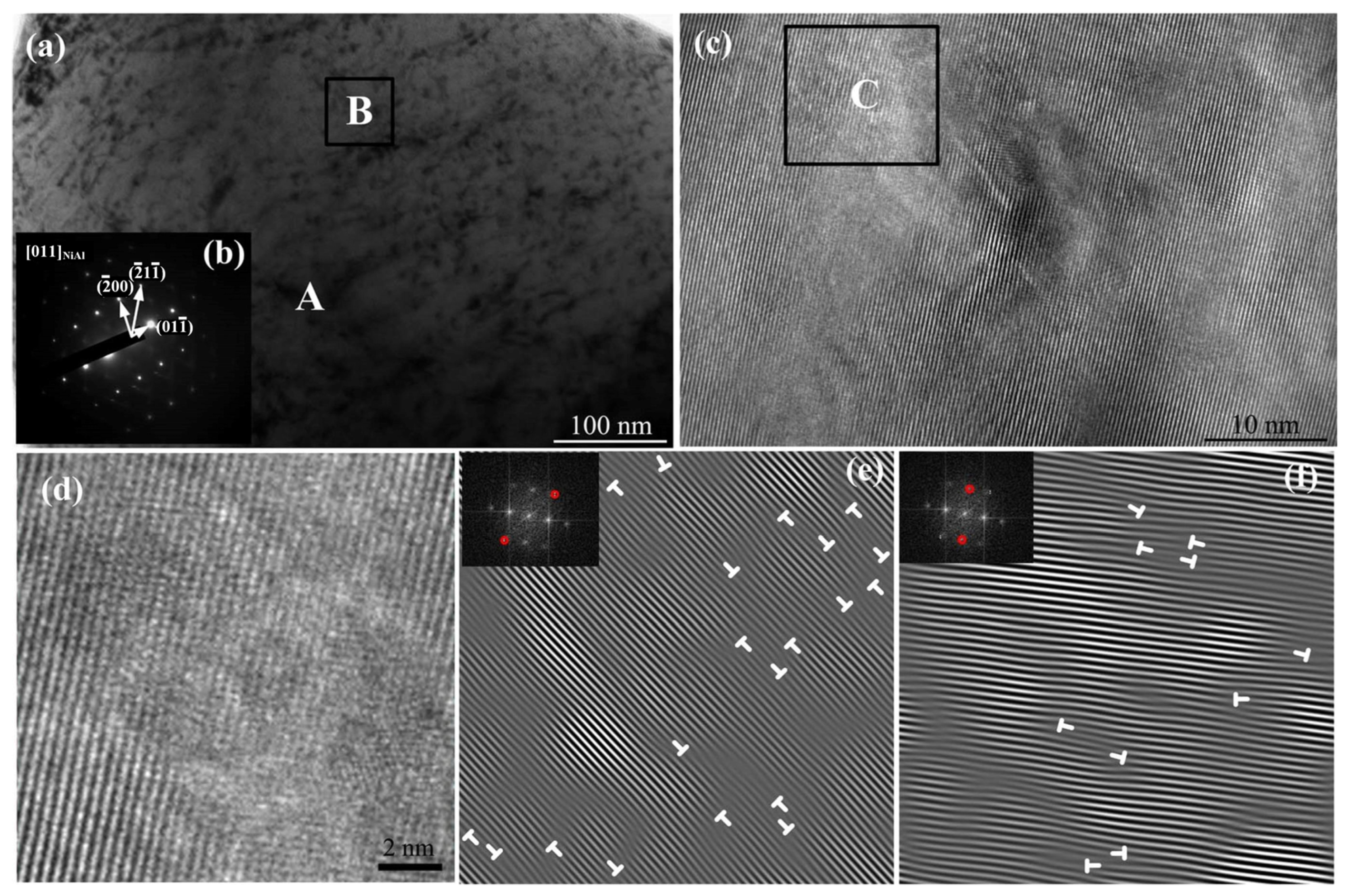
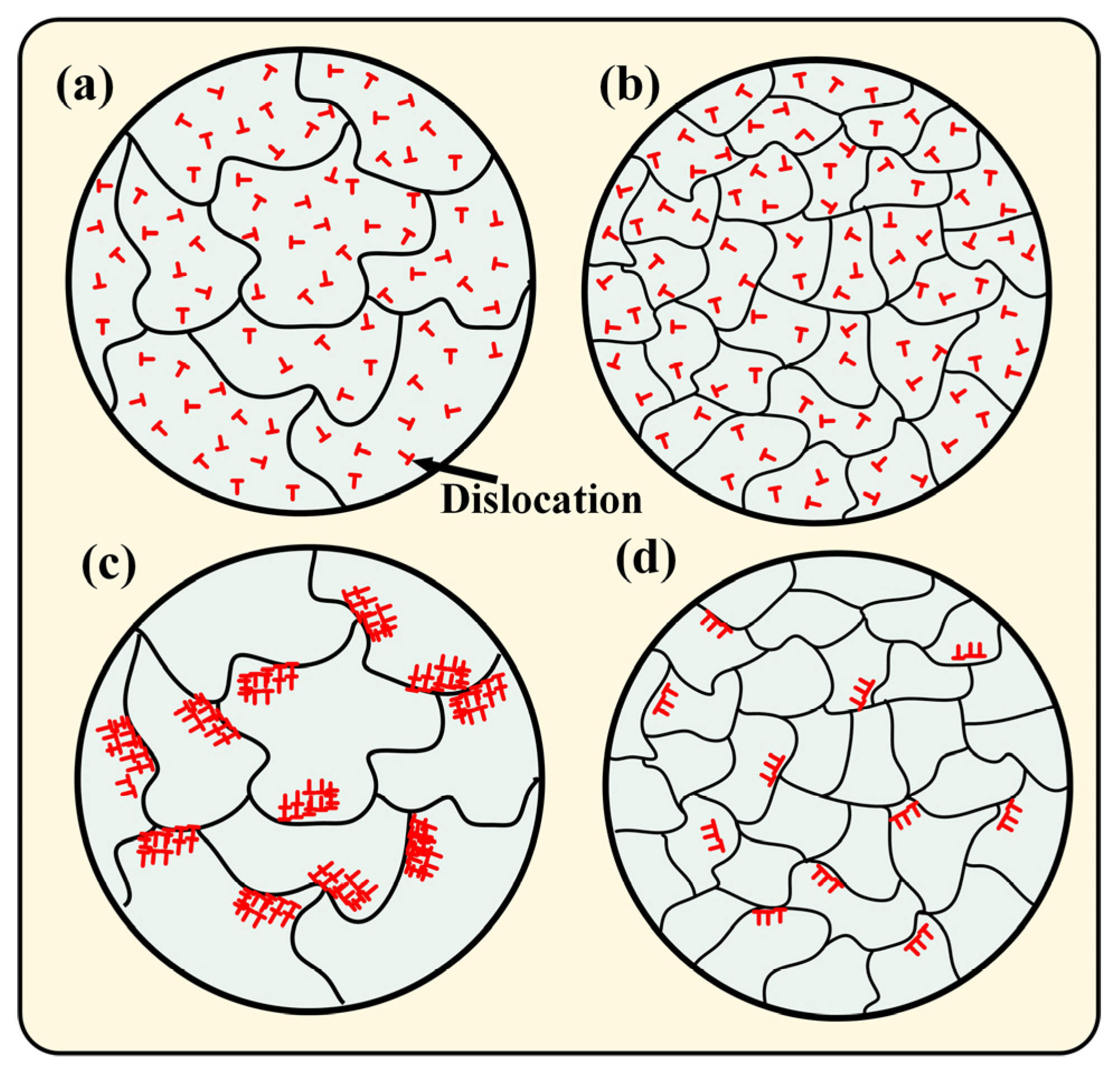
3.3.2. Dislocation Multiplication Behavior of NiAl Alloy during Compression

Table 2 gives the dislocation density of the NiAl alloy fabricated before and after compression. As indicated, the dislocation densities are 5.08 × 1011 cm−2 and 5.92 × 1011 cm−2, respectively, indicating that dislocations can largely proliferate (0.84 × 1011 cm−2) in the alloy after compression. The microstructure evolution before and after fracture also indicate that the dislocation of NiAl alloy increases to a great extent after fracture. This is because a fast cooling rate results in a large degree of undercooling and large internal stress, thus leading to a high proportion of dislocations and lattice distortions in the alloy. Therefore, the higher strength, hardness and work-hardening ability of the NiAl alloy is attributed to the higher dislocation density [43].

4. Conclusions

Most of the methods currently used to synthesize and prepare NiAl alloys have the disadvantages of complexity, high cost, and high energy consumption. In this study, a NiAl alloy with fine grain size and high dislocation density was successfully prepared by CSHP, which allows for the rapid and efficient preparation of NiAl alloys at a low cost using very little energy. The relationship between microstructure and properties of the alloy was investigated. The microstructure evolution behavior, mechanical properties and strengthening mechanism were revealed. This study is anticipated to offer a novel method to synthesize a NiAl alloy with superior mechanical properties. The conclusions were as follows:
(1)
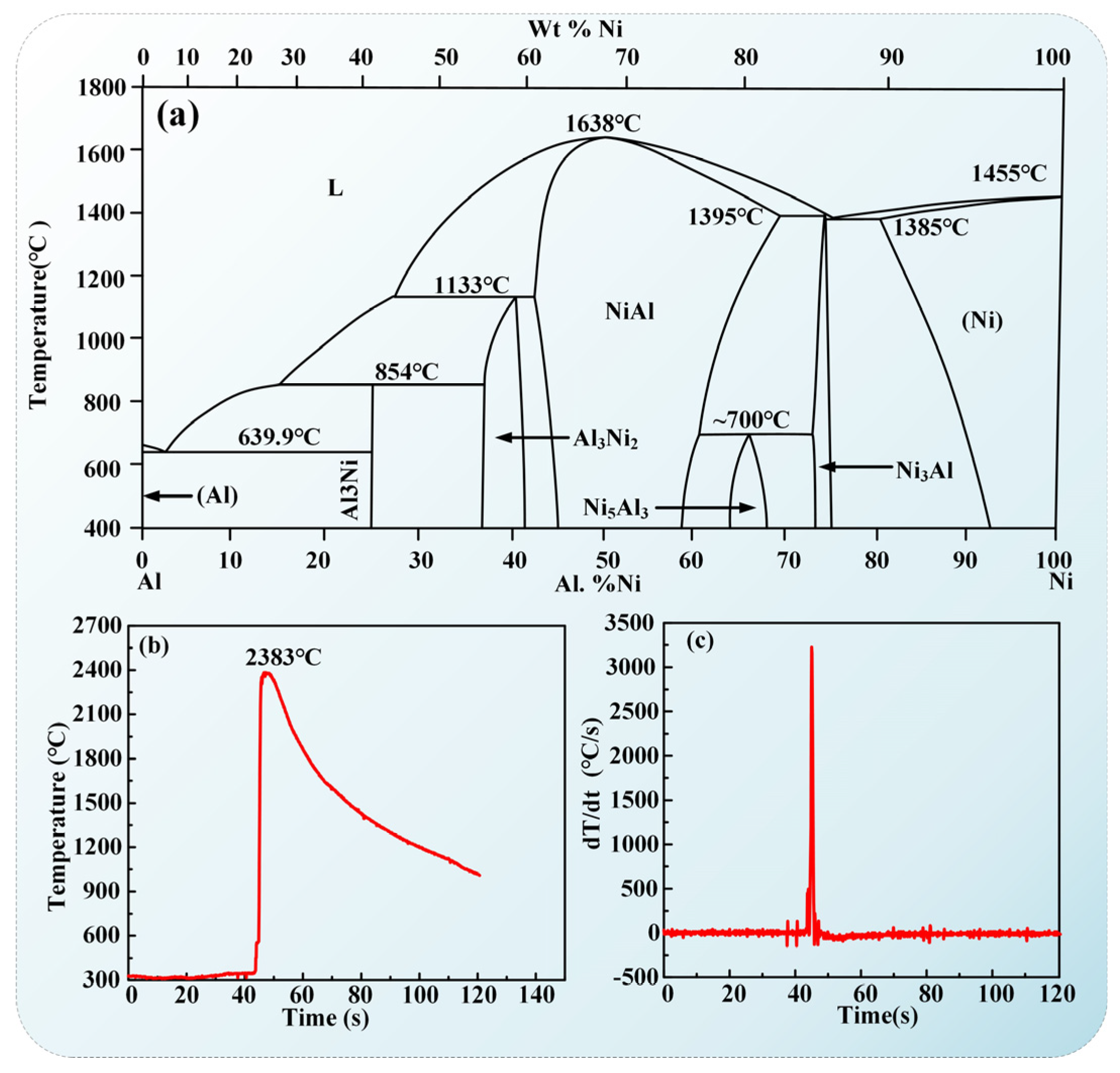
The grain size of NiAl alloy prepared by CSHP is significantly refined under rapid solidification due to the instantly completed combustion synthesis of NiAl intermetallics in the Ni–Al system. That is to say, the fast cooling rate results in a large degree of undercooling, which greatly reduces the size of the critical nucleus in spontaneous nucleation, and thus leads to grain refinement. At the same time, the fast cooling rate and forming under pressure in the solidification process produce a lot of internal stress, which forms a large number of dislocations in the as-cast microstructures.
(2)
The fracture strain of the NiAl intermetallics prepared by CSHP is significantly higher than that of NiAl alloys prepared by other methods. The compression property (1005 MPa) at RT is greater than that of the NiAl alloy prepared by the HPES method (about 632 MPa), while is slightly lower than that of the corresponding NiAl alloys treated by HPES and HIP (1050 MPa). In addition, the NiAl alloy prepared by CSHP has excellent work-hardening ability.
(3)
The main strengthening mechanism of the NiAl alloy is fine grain strengthening, followed by dislocation strengthening. The grain refinement not only increases the grain boundaries but also reduces the stress concentration in the deformation process, thus crack initiation and propagation become difficult.

Author Contributions

Conceptualization, J.-Y.H., S.Z., L.-J.Z., F.P. and F.Q.; data curation, J.-Y.H., S.Z., L.-J.Z., F.P., H.-L.Z. and F.Q.; formal analysis, J.-Y.H., S.Z., L.-J.Z., F.P. and H.-L.Z.; investigation, J.-Y.H., S.Z., L.-J.Z., F.P., H.-L.Z. and F.Q.; supervision, S.Z., F.P. and F.Q.; writing—review and editing, J.-Y.H., S.Z., L.-J.Z., F.P., H.-L.Z. and F.Q. All authors have read and agreed to the published version of the manuscript.

Funding

This work is supported by the undergraduate Innovation Fund of Jilin University, China (No. S202210183219).

Institutional Review Board Statement

Not applicable.

Informed Consent Statement

Not applicable.

Data Availability Statement

Data sharing is not applicable.

Conflicts of Interest

The authors declare no conflict of interest.

References

  1. Bhaumik, S.K.; Divakar, C.; Rangaraj, L.; Singh, A.K. Reaction sintering of NiAl and TiB2–NiAl composites under pressure. Mater. Sci. Eng. A 1998, 257, 341–348. [Google Scholar] [CrossRef]
  2. Darolia, R.; Walston, W.S.; Noebe, R.; Garg, A.; Oliver, B.F. Mechanical properties of high purity single crystal NiAl. Intermetalics 1999, 7, 1195–1202. [Google Scholar] [CrossRef]
  3. Hu, W.; Weirich, T.; Hallstedt, B.; Chen, H.; Zhong, Y.; Gottstein, G. Interface structure, chemistry and properties of NiAl composites fabricated from matrix-coated single-crystalline Al2O3 fibres (sapphire) with and without an hBN interlayer. Acta Mater. 2006, 54, 2473–2488. [Google Scholar] [CrossRef]
  4. Noebe, R.D.; Bowman, R.R.; Nathal, M.V. Physical and mechanical properties of the B2 compound NiAl. Int. Mater. Rev. 1993, 38, 193–232. [Google Scholar] [CrossRef]
  5. Pike, L.M.; Chang, Y.A.; Liu, C.T. Point defect concentrations and hardening in binary B2 intermetallics. Acta Mater. 1997, 45, 3709–3719. [Google Scholar] [CrossRef]
  6. Ni, X.; Wang, X.; Chen, C. Relationship of structural stability and long-range-order parameter for stoichiometry NiAI. J. Univ. Sci. Technol. Beijing 1996, 3, 75. [Google Scholar]
  7. Miracle, D.B. Overview No. 104 The physical and mechanical properties of NiAl. Acta Metall. Mater. 1993, 41, 649–684. [Google Scholar] [CrossRef]
  8. Terada, Y.; Ohkubo, K.; Mohri, T.; Suzuki, T. Effects of ternary additions on thermal conductivity of NiAl. Intermetallics 1999, 7, 717–723. [Google Scholar] [CrossRef]
  9. Whittenberger, J.D.; Noebe, R.D.; Joslin, S.M.; Oliver, B.F. Elevated temperature compressive slow strain rate properties of several directionally solidified NiAl–(Nb,Mo) alloys. Intermetallics 1999, 7, 627–633. [Google Scholar] [CrossRef]
  10. Du, X.-h.; Gao, C.; Wu, B.-l.; Zhao, Y.-h.; Wang, J.-j. Enhanced compression ductility of stoichiometric NiAl at room temperature by Y and Cu co-addition. Int. J. Miner. Metall. Mater. 2012, 19, 348. [Google Scholar] [CrossRef]
  11. Dai, J.Y.; Xing, Z.P.; Wang, Y.G.; Li, D.X.; Guo, J.T.; He, L.L.; Ye, H.Q. HREM study of TiB2/NiAl interfaces in a NiAl-TiB2 in-situ composite. Mater. Lett. 1994, 20, 23–27. [Google Scholar] [CrossRef]
  12. Michalski, A.; Jaroszewicz, J.; Rosiński, M.; Siemiaszko, D. NiAl–Al2O3 composites produced by pulse plasma sintering with the participation of the SHS reaction. Intermetallics 2006, 14, 603–606. [Google Scholar] [CrossRef]
  13. Plazanet, L.; Tetard, D.; Nardou, F. Effect of SiC and ZrO2 particles on the mechanical properties of NiAl. Compos. Sci. Technol. 1999, 59, 537–542. [Google Scholar] [CrossRef]
  14. Yeh, C.L.; Su, S.H.; Chang, H.Y. Effects of TiC addition on combustion synthesis of NiAl in SHS mode. J. Alloys Compd. 2005, 398, 85–93. [Google Scholar] [CrossRef]
  15. Zwigl, P.; Dunand, D.C. Transformation-mismatch plasticity of NiAl/ZrO2 composites—Experiments and continuum modeling. Mater. Sci. Eng. A 2001, 298, 63–72. [Google Scholar] [CrossRef] [Green Version]
  16. Dong, B.-X.; Li, Q.-Y.; Shu, S.-L.; Duan, X.-Z.; Zou, Q.; Han, X.; Yang, H.-Y.; Qiu, F.; Jiang, Q.-C. Investigation on the elevated-temperature tribological behaviors and mechanism of Al-Cu-Mg composites reinforced by in-situ size-tunable TiB2-TiC particles. Tribol. Int. 2023, 177, 107943. [Google Scholar] [CrossRef]
  17. Guo, J.T.; Xing, Z.P. Investigation of NiAl–TiB2 in situ composites. J. Mater. Res. 1997, 12, 1083–1090. [Google Scholar] [CrossRef]
  18. Xing, Z.P.; Guo, J.T.; Yu, L.G.; Dai, J.Y.; Hu, Z.Q. Influence of HIP processing on the interface of NiAl TiC in situ composite. Mater. Lett. 1996, 28, 361–363. [Google Scholar] [CrossRef]
  19. Dong, M.G.; Tishkevich, D.I.; Hanfi, M.Y.; Semenishchev, V.S.; Sayyed, M.I.; Zhou, S.Y.; Grabchikov, S.S.; Khandaker, M.U.; Xue, X.X.; Zhaludkevich, A.L.; et al. WCu composites fabrication and experimental study of the shielding efficiency against ionizing radiation. Radiat. Phys. Chem. 2022, 200, 110175. [Google Scholar] [CrossRef]
  20. Sun, Y.; Lin, P.; Yuan, S.J. A novel method for fabricating NiAl alloy sheet components using laminated Ni/Al foils. Mater. Sci. Eng. A 2019, 754, 428–436. [Google Scholar] [CrossRef]
  21. Tishkevich, D.I.; Zubar, T.I.; Zhaludkevich, A.L.; Razanau, I.U.; Vershinina, T.N.; Bondaruk, A.A.; Zheleznova, E.K.; Dong, M.; Hanfi, M.Y.; Sayyed, M.I.; et al. Isostatic Hot Pressed W–Cu Composites with Nanosized Grain Boundaries: Microstructure, Structure and Radiation Shielding Efficiency against Gamma Rays. Nanomaterials 2022, 12, 1642. [Google Scholar] [CrossRef] [PubMed]
  22. Muñoz-Saldaña, J.; Valencia-Ramirez, A.; Castillo-Perea, L.A.; Díaz-De la Torre, S.; Caceres-Diaz, L.A.; Alvarado Orozco, J.M.; Giraldo Betancur, A.L.; Schulz, U. Oxidation behavior of dense Yttrium doped B2-NiAl bulk material fabricated by ball milling self-propagating high-temperature synthesis and densified by spark plasma sintering. Surf. Coat. Technol. 2021, 421, 127448. [Google Scholar] [CrossRef]
  23. Nikbakht, R.; Assadi, H. Phase-field modelling of self-propagating high-temperature synthesis of NiAl. Acta Mater. 2012, 60, 4041–4053. [Google Scholar] [CrossRef]
  24. Shekari, M.; Adeli, M.; Khobzi, A.; Kobashi, M.; Kanetake, N. Induction-activated self-propagating, high-temperature synthesis of nickel aluminide. Adv. Powder Technol. 2017, 28, 2974–2979. [Google Scholar] [CrossRef]
  25. Sheng, L.; Zhang, W.; Guo, J.; Yang, F.; Liang, Y.; Ye, H. Effect of Au addition on the microstructure and mechanical properties of NiAl intermetallic compound. Intermetallics 2010, 18, 740–744. [Google Scholar] [CrossRef]
  26. Zhou, J.; Guo, J.T. Effect of Ag alloying on microstructure, mechanical and electrical properties of NiAl intermetallic compound. Mater. Sci. Eng. A 2003, 339, 166–174. [Google Scholar] [CrossRef]
  27. Baghdadi, A.H.; Rajabi, A.; Selamat, N.F.M.; Sajuri, Z.; Omar, M.Z. Effect of post-weld heat treatment on the mechanical behavior and dislocation density of friction stir welded Al6061. Mater. Sci. Eng. A 2019, 754, 728–734. [Google Scholar] [CrossRef]
  28. Guo, H.-B.; Wang, X.-Y.; Li, J.; Wang, S.-X.; Gong, S.-K. Effects of Dy on cyclic oxidation resistance of NiAl alloy. Trans. Nonferrous Met. Soc. China 2009, 19, 1185–1189. [Google Scholar] [CrossRef]
  29. Yin, S. Self-Propagating High Temperature Synthesis Technology and Materials; Metallurgical Industry Press: Beijing, China, 1995. [Google Scholar]
  30. Afrin, N.; Chen, D.L.; Cao, X.; Jahazi, M. Strain hardening behavior of a friction stir welded magnesium alloy. Scr. Mater. 2007, 57, 1004–1007. [Google Scholar] [CrossRef]
  31. Qiu, F.; Shen, P.; Jiang, Z.; Liu, T.; Jiang, Q. Strong work-hardening effect in a multiphase ZrCuAlNiO alloy. Appl. Phys. Lett. 2008, 92, 151912. [Google Scholar] [CrossRef]
  32. Van Swygenhoven, H.; Spaczer, M.; Caro, A.; Farkas, D. Competing plastic deformation mechanisms in nanophase metals. Phys. Rev. B 1999, 60, 22–25. [Google Scholar] [CrossRef]
  33. Wang, Y.M.; Ma, E.; Chen, M.W. Enhanced tensile ductility and toughness in nanostructured Cu. Appl. Phys. Lett. 2002, 80, 2395–2397. [Google Scholar] [CrossRef]
  34. Chen, X.H.; Lu, L. Work hardening of ultrafine-grained copper with nanoscale twins. Scr. Mater. 2007, 57, 133–136. [Google Scholar] [CrossRef]
  35. Lu, L.; Chen, X.; Huang, X.; Lu, K. Revealing the Maximum Strength in Nanotwinned Copper. Science 2009, 323, 607–610. [Google Scholar] [CrossRef]
  36. Yi, H.-l.; Du, L.-x.; Wang, G.-d.; Liu, X.-h. Strengthening Mechanism of a New 700 MPa Hot Rolled High Strength Steel. J. Iron Steel Res. Int. 2008, 15, 76–80. [Google Scholar] [CrossRef]
  37. Dong, B.-X.; Li, Q.; Wang, Z.-F.; Liu, T.-S.; Yang, H.-Y.; Shu, S.-L.; Chen, L.-Y.; Qiu, F.; Jiang, Q.-C.; Zhang, L.-C. Enhancing strength-ductility synergy and mechanisms of Al-based composites by size-tunable in-situ TiB2 particles with specific spatial distribution. Compos. Part B Eng. 2021, 217, 108912. [Google Scholar] [CrossRef]
  38. Dong, B.-X.; Li, Q.; Yang, H.-Y.; Liu, T.-S.; Qiu, F.; Shu, S.-L.; Jiang, Q.-C.; Zhang, L.-C. Synergistic optimization in solidification microstructure and mechanical performance of novel (TiCxNy−TiB2)p/Al nanocomposites: Design, tuning and mechanism. Compos. Part A Appl. Sci. Manuf. 2022, 155, 106843. [Google Scholar] [CrossRef]
  39. Hall, E.O. The Deformation and Ageing of Mild Steel: III Discussion of Results. Proc. Phys. Soc. Sect. B 1951, 64, 747. [Google Scholar] [CrossRef]
  40. Yang, H.-Y.; Yan, Y.-F.; Liu, T.-S.; Dong, B.-X.; Chen, L.-Y.; Shu, S.-L.; Qiu, F.; Jiang, Q.-C.; Zhang, L.-C. Unprecedented enhancement in strength-plasticity synergy of (TiC + Al6MoTi + Mo)/Al cermet by multiple length-scale microstructure stimulated synergistic deformation. Compos. Part B Eng. 2021, 225, 109265. [Google Scholar] [CrossRef]
  41. Liu, T.-S.; Qiu, F.; Yang, H.-Y.; Liu, S.; Jiang, Q.-C.; Zhang, L.-C. Exploring the potential of FSW-ed Al–Zn–Mg–Cu-based composite reinforced by trace in-situ nanoparticles in manufacturing workpiece with customizable size and high mechanical performances. Compos. Part B Eng. 2023, 250, 110425. [Google Scholar] [CrossRef]
  42. Wang, Y.M.; Ma, E. Three strategies to achieve uniform tensile deformation in a nanostructured metal. Acta Mater. 2004, 52, 1699–1709. [Google Scholar] [CrossRef]
  43. Bao, H.-S.; Cheng, S.-C.; Liu, Z.-D.; Tan, S.-P. Aging precipitates and strengthening mechanism of T122 boiler steel. J. Iron Steel Res. Int. 2010, 17, 67–73. [Google Scholar] [CrossRef]
Figure 1. Preparation process of Ni-Al; (a) ball milling; (b) cold Pressing; (c) combustion synthesis reaction process; (d) the prepared NiAl alloy; and (e) synthesis mechanism.
Metals 13 01143 g001
Figure 2. (a) The XRD pattern of the NiAl fabricated by CSHP; (b) SEM image of NiAl alloy; (c) the distribution of element Al; and (d) the distribution of element Ni.
Metals 13 01143 g002
Figure 3. (a) The phase diagram of Ni-Al; (b) the solidification cooling curve of NiAl alloy; and (c) the first derivative of the solidification cooling curve of NiAl alloy.
Metals 13 01143 g003
Figure 4. (a) TEM pictures of the NiAl following fracture; (b) SAED pattern at the area A; (c) a HRTEM image of the area B in Figure 3a; (d) a magnified image of the area C in Figure 4c; and (e,f) IFFT images of the area C in Figure 4d, with insets being the FFT images.
Metals 13 01143 g004
Figure 5. Room temperature (a) Vickers hardness, (b) compression stress and (c) fracture strain of the NiAl alloys; (d) Hc of the NiAl alloys fabricated by the different methods; (e) normalized work-hardening rate vs. true strain curves; and (f) n vs. true strain curves.
Metals 13 01143 g005
Figure 6. (a) The strain−stress curve of NiAl intermetallic compound fabricated by the CSHP technique during continuous compression test (1.0 × 10⁻¹ s−1) and (b) room temperature compression engineering strain–stress curve obtained in a strain change test with the strain rate varied from 1.0 × 10⁻⁵ s−1 to 1.25 × 10⁻² s−1 for NiAl intermetallic compound fabricated by CSHP.
Metals 13 01143 g006
Figure 7. The schematic diagram of (a,b) strengthening mechanism and (c,d) toughening mechanism of the NiAl alloy after CSHP.
Metals 13 01143 g007
Table 1. RT mechanical properties and work-hardening capacity (Hc) of the NiAl alloys fabricated by the different methods. Partial data from Ref. [17].
Alloy CompositionPreparation MethodMicrohardness (HV)True Yield Strength (MPa)True Fracture Strength (MPa)True Fracture Strain (%)Work Hardening Ability (Hc)
NiAlCombustion synthesis + hot pressing360419100521.61.40
HPES31442963240.47
HPES + HIP308465105010.51.25
HPES + HT31542090610.81.16
Table 2. The dislocation density of the NiAl fabricated by CSHP technique before and after compression.
AlloyCompression of Pre-Dislocation Density (cm−2)Dislocation Density after Compression (cm−2)Dislocation Multiplication before and after Compression (cm−2)
NiAl5.08 × 10115.92 × 10110.84 × 1011
Disclaimer/Publisher’s Note: The statements, opinions and data contained in all publications are solely those of the individual author(s) and contributor(s) and not of MDPI and/or the editor(s). MDPI and/or the editor(s) disclaim responsibility for any injury to people or property resulting from any ideas, methods, instructions or products referred to in the content.

