Article

The Corrosion and Wear-Corrosion of the Iron-Base Amorphous Coating Prepared by the HVOF Spraying

1
Department of Optoelectronics and Materials Technology, National Taiwan Ocean University, Keelung 20224, Taiwan
2
Chung Yo Materials Co., Ltd., Kaohsiung 82059, Taiwan
*
Author to whom correspondence should be addressed.
Metals 2023, 13(6), 1137; https://doi.org/10.3390/met13061137
Submission received: 19 May 2023 / Revised: 16 June 2023 / Accepted: 16 June 2023 / Published: 18 June 2023

Abstract

:
In this work, the corrosion behaviors of an iron-based amorphous coating produced by high-velocity oxy-fuel (HVOF) spraying were investigated. Potentiodynamic and potentiostatic polarization and corrosion pin-on-ring (corrosion-wear) tests were conducted to evaluate the corrosive properties of the coating as compared with the 316L substrate. The corrosion behaviors of the 316L substrate and coated sample were tested in 3.5 wt.% NaCl, 1 M HCl, and 0.5 M H2SO4 solutions. In the 3.5 wt.% NaCl and 1 M HCl solutions, the corrosion resistance of the coating was a little inferior or equivalent to that of the 316L substrate after potentiodynamic polarization tests. In the 0.5 M H2SO4 solution, the two tested samples exhibited wide passivated zones in the polarization curves. In such a mild acid, the corrosion resistance of the 316 substrate was superior to that of the amorphous coating, possibly due to the presence of defects in the coating. After potentiodynamic polarization tests, the linkage of initial fine pits into large, deep pores was seen in the corroded 316L substrate. By contrast, extensive corrosion along with preferentially corroded defective sites was seen in the coating. Moreover, the coating exhibited a much higher resistance to corrosion-wear, or low weight loss, in 3.5 wt.% NaCl solution. After the corrosion-wear tests, deep furrows were present in the 316L substrate, whereas a rubbed smooth surface and a corroded zone were seen in the coating. The greater weight loss of the 316L substrate confirmed its poor resistance to corrosion-wear relative to the amorphous coating in 3.5 wt.% NaCl solution.

1. Introduction

High-velocity oxy-fuel (HVOF) spraying can produce a coating of distinctive surface properties for industrial structures and components in aggressive environments [1,2,3]. The feedstock powders are heated and accelerated to extremely high speed by the spraying gun, and then they constantly impact with and are deposited onto the substrate surface to form a dense, low-defect coating [4,5]. It is reported that high compressive residual stress is induced inside the HVOF coating [1]. In addition, HVOF can be used to prepare different coatings, including metallic [6,7], cermet [8], and ceramic [9,10] materials.
During the past few decades, bulk glassy metals have been developed in different alloy systems [11,12,13,14,15,16]. Among the different amorphous alloys, iron-based ones have been attracting much attention because of their inherent excellent mechanical and chemical properties, as well as their cost-effectiveness [17,18,19,20]. However, the high cooling rates required after solidification to form the amorphous phase limit their applicability as prospective structural materials. A good alternative is to use an iron-based amorphous alloy as the feedstock powder for a thermal spray coating [21,22,23,24,25,26,27,28,29]. Moreover, HVOF is advantageous for forming an amorphous coating because the high cooling rate of the deposits enhances the formation of the amorphous phase [30,31]. With an increase in spraying power, the microhardness and wear resistance of the amorphous Fe-10W-4Cr-3Ni-2Mo-4B-4Si-1C coating increases [32]. The bonding strength of the Fe48Cr15Mo14C15B6Y2 amorphous coating increases with increasing substrate roughness but decreases with coating thickness [33]. Moreover, an amorphous coating produced from fine powder is more likely to have a dense structure, while one from coarse powder will have superior corrosion resistance [34]. The low wear rate of the Fe52Cr15Mo25C3B2Y3 amorphous coating is associated with the decreased porosity in the coating [35], which can be affected by the fuel and oxygen flow rate of HVOF spraying [36]. In both 3.5% NaCl and 0.5 M H2SO4 solutions, the corrosion resistance of the Fe43Cr16Mo16C15B10 coating in the amorphous form is superior to that in the crystalline form [37]. It is reported that an amorphous coating has been successfully applied to extend the service life of marine pumps [25,27].
The Fe-(Cr,Mo)-(C,B) system has been noted to have a high glass-forming ability [38,39,40,41,42,43], and minor elements can be added to it to further improve that ability. In fact, the amorphous feedstock for a coating need not have the same high glass-forming ability as for large glassy structural components. A lean alloy composition (Fe-2.5Cr-6.7Si-2.5B-0.7C wt%) has been developed for an amorphous thermal coating [44]. In this work, to reduce the high cost of the Mo, Co, and Y elements, the Mo content was lowered but other elements were added to the FeCrMoCB system to maintain the glass-forming ability. Moreover, such a modified alloy powder can be used to form an amorphous coating for conventional thermal spraying. Herein, a seven-element alloy system, FeCrNiMoCBSi, is proposed as an alternative to a thermal spray coating. In the open literature, the application of an iron-based amorphous coating to improve the corrosion and wear resistance of structural components is an important issue and has received much attention in the past few years [45,46,47]. In this study, the corrosion behaviors of the coated samples were studied in three distinct solutions using potentio-polarization tests and the results were compared with those of the 316L substrate. The microstructures of the investigated samples were examined using a scanning electron microscope (SEM). The corrosion-wear properties of distinct samples were determined with a pin-on-ring corrosion abrasion instrument.

2. Materials and Experimental Procedures

2.1. Thermal Spray and Microstructural Investigations

The amorphous feedstock powder (7 elements) used in this work was fabricated by Ar-gas atomization and provided by Chung Yo Materials Co., Ltd. (Kaohsiung City, Taiwan). The chemical composition of the feedstock powder in weight percent (wt%) was as follows: 21.53 Cr, 13.65 Ni, 14.41 Mo, 2.07 C, 2.73 Si, 2.30 B, and the balance Fe. The amorphous powder ranged from +15 to −45 μm in size. HVOF was applied to perform the amorphous coating onto the 316L plates of 6 mm thickness and the 316 round bars with a diameter of 20 mm. The process parameters of HVOF spraying were as follows: a kerosine flow rate of 5 GPH, an oxygen flow rate of 1700 SCFH, a gun moving speed of 600 mm/s, a spraying distance of 380 mm, and a powder feeding rate of 30 g/min. The total thickness of the coating was about 150 μm. The phases of the powder and coating were analyzed with a D2 X-ray diffractometer (XRD, Bruker, Billerica, MA, USA) using Cu Kα radiation. A 404 F3 high-temperature differential scanning calorimeter (HT-DSC, Netzsch, Selb, Germany) was applied to determine the transformation temperature of the powder. The samples were heated to about 1400 °C at a heating rate of 10 °C/min, followed by cooling to room temperature. The samples for metallographic examinations were ground with SiC papers up to 1500 grit, then polished with a colloidal silica suspension. The microstructures of the prepared specimens were inspected with a 4800 SEM (Hitachi, Tokyo, Japan). The micro-hardnesses of the distinct samples were determined using an MVK-G1500 Vickers hardness tester (Mitutoyo, Kanagawa, Japan) loaded at 50 gf and a dwell time of 15 s.

2.2. Corrosion and Corrosion-Wear Resistance Determinations

The potentiodynamic polarization curves of the coating were determined in a standard three-electrode cell system with a Zahner-Elektrik potentiostate (Zahner-Elektrik, Landkreis Kronach, Germany) and compared with those of the 316L substrate. A saturated calomel electrode (SCE) was used as the reference electrode and a platinum plate acted as the counter electrode. The potentiodynamic polarization tests were carried out at room temperature in three solutions within a potential range from −1.0 V to +2.0 V and at a scanning rate of 1 mV/sec. Three testing solutions including 3.5 wt.% NaCl, 1 M HCl, and 0.5 M H2SO4 were applied in this work. Corrosion-wear tests were performed using coated cylindrical samples with dimensions of about 20.3 mm diameter × 10 mm. An alumina cube (21 mm × 21 mm × 21 mm) with a hardness of about Hv 1450 was used as the wear counter. For the corrosion-wear test, the applied load was 29.4 N, the rotating speed was 200 rpm, and the duration was 30 min.

3. Results

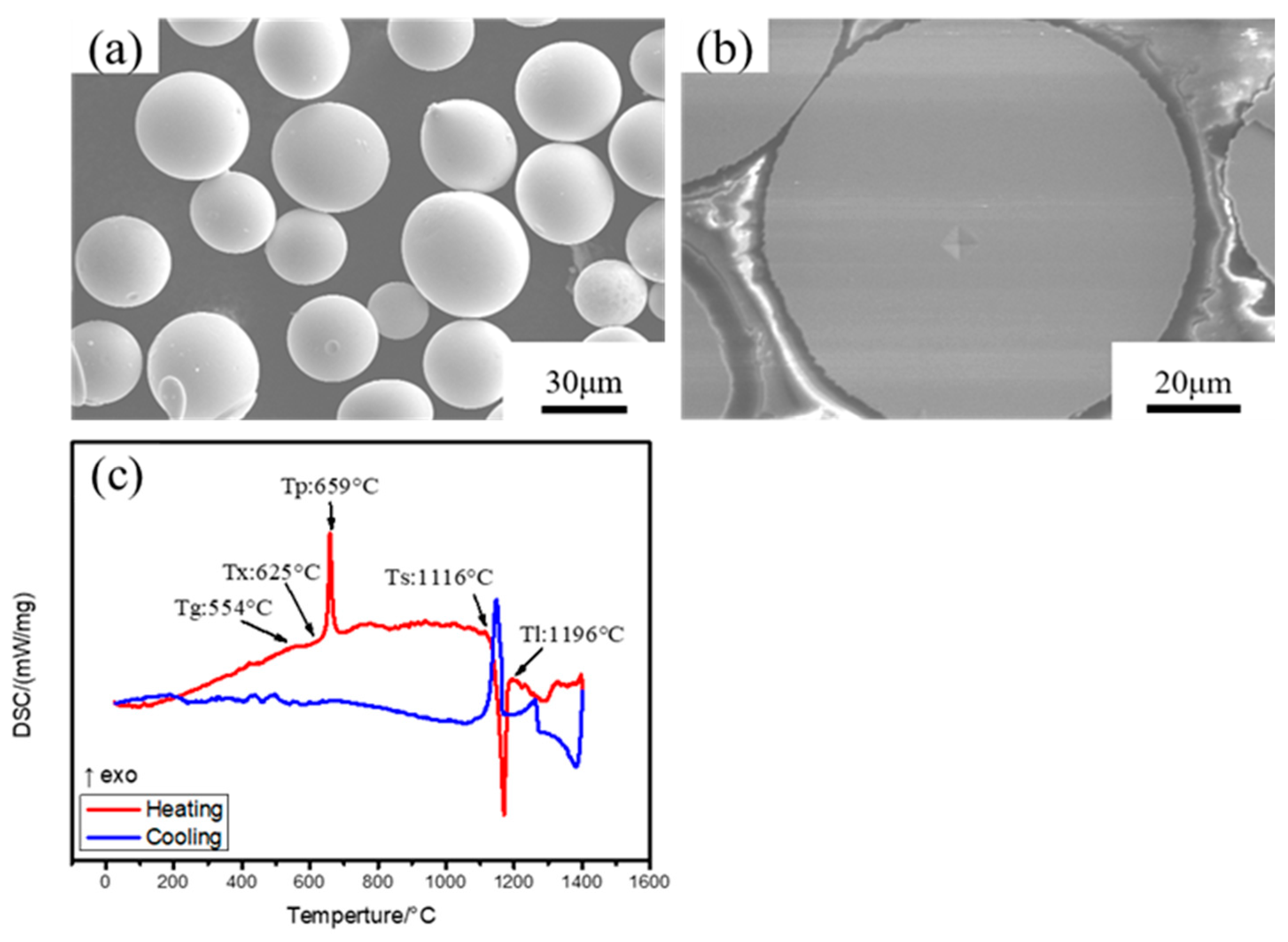
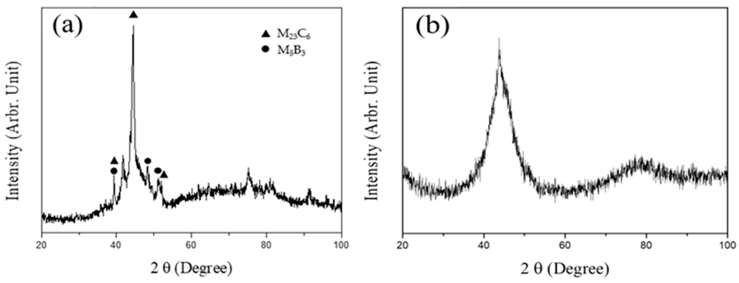
3.1. Transformation Temperature of the Feedstock Powders and Phase Identification

Figure 1 shows the morphology of the feedstock powder and its differential scanning calorimeter (DSC) curve, which was used to identify the phase transformation temperature. Figure 1a displays the amorphous powder in a round shape with diameters of 15–45 μm for HVOF spraying. It was noticed that the external surfaces of the powders were very smooth and lacked any sign of dendritic structure. As shown in Figure 1b, the cross-sectional view of the powder with micro-hardness indentation revealed that the powder hardness could be as high as Hv 1400, which was much harder than the conventional alloys in the market. It was expected that the amorphous coating would have a very high hardness. Figure 1c presents the DSC curve of the feedstock powder; the red line and the blue line are the temperature-rising and the temperature-cooling curves, respectively. The DSC curves of the amorphous powder displayed the glass transition temperature (Tg, 554 °C), crystallization temperature (Tx, 625 °C), peak crystallization temperature (Tp, 659 °C), solidus temperature (TS, 1116 °C), and liquidus temperature (TL, 1196 °C). The results indicated that the addition of certain amounts of C, B, and Si into the Fe-based amorphous alloy had caused a drop of about 250 °C in the liquidus temperature as compared with that of the conventional alloy steels.
Figure 2 shows the X-ray diffractometer (XRD) patterns of the powder and coating. The results indicated broad halo peaks in both samples, indicating very high amorphous contents. It was noticed that a few sharp peaks were present in the XRD pattern of the powder, indicating the formation of second phases or fine precipitates inside the powder. Those precipitates in the feedstock powders could be the complex alloy carbides, borides, and intermetallics, as shown in Figure 2a. By contrast, no such precipitates were found in the coating; their absence could be associated with the high cooling rate of the coating after HVOF spraying. Overall, the glass-forming ability of this developed FeCrNiMoCBSi powder could meet the requirements of thermal spray coating. Moreover, the high cooling rate of HVOF spraying also contributed to forming an amorphous phase in the coating, as compared with the feedstock powder.

3.2. SEM Images of the Coating

Figure 3 shows the SEM images of the top and cross-sectional views of the amorphous coating. Figure 3a shows the surface appearance of the amorphous coating; it reveals the partially molten zone mixed with residual powders. The partially molten powder could be accelerated to extremely high speed in the HVOF combustion chamber. The cross-sectional images (Figure 3b,c) of the coating indicated that it was a dense layer showing the HVOF deposits, and only very fine voids were visible. As shown in Figure 3b, the coating had a thickness of about 150 μm and there was a ripple-like interface between the coating and the 316L substrate. It was noticed that fine porosities (indicated by the arrows) were trapped along the coating interface (Figure 3b). It is reported that large voids located between flattened droplets are due to the loosely packed layer, while pinholes are the cause of shrinkage porosity [48]. Those pinholes in the coating could be related to the shrinkage of the molten amorphous layer. Moreover, the use of a fine powder for HVOF spraying can reduce porosity [34]. The micro-hardness of the as-deposited coating was above Hv 1120 (Figure 3c), indicating that it was obviously harder than conventional alloy steels and precipitation-hardening alloys. This hardness could be attributed to the influence of minute defects in the coating, which would lower its hardness to less than that of the feedstock powder. A nano-indenter loaded at 2000 μN was used to measure the hardness and elastic modulus of the amorphous coating (indicated by the circle in Figure 3d) and the 316L substrate. Detracting those data highly deviated from the average, the nano-hardness of the coating fell in the range of 11–14 GPa and had an elastic modulus of 200–220 GPa. Moreover, the nano-hardness of the 316L substrate was within the range of 2.5–4.6 GPa and had an elastic modulus of 180–200 GPa. It was obvious that the Fe-based amorphous coating had about the same elastic modulus as that of commercial alloy steels, but was much harder than the alloy steels. In fact, the elastic modulus of the metals is strongly dependent on the atomic attraction force between atoms, therefore, the Fe-based amorphous coating had the similar elastic property as the commercial steels. Overall, the results of nano-indentation were roughly consistent with the micro-hardness measurement. Nevertheless, the amorphous coating provided by HVOF spraying was expected to have a high wear resistance to external loading, as compared with the conventional alloys.

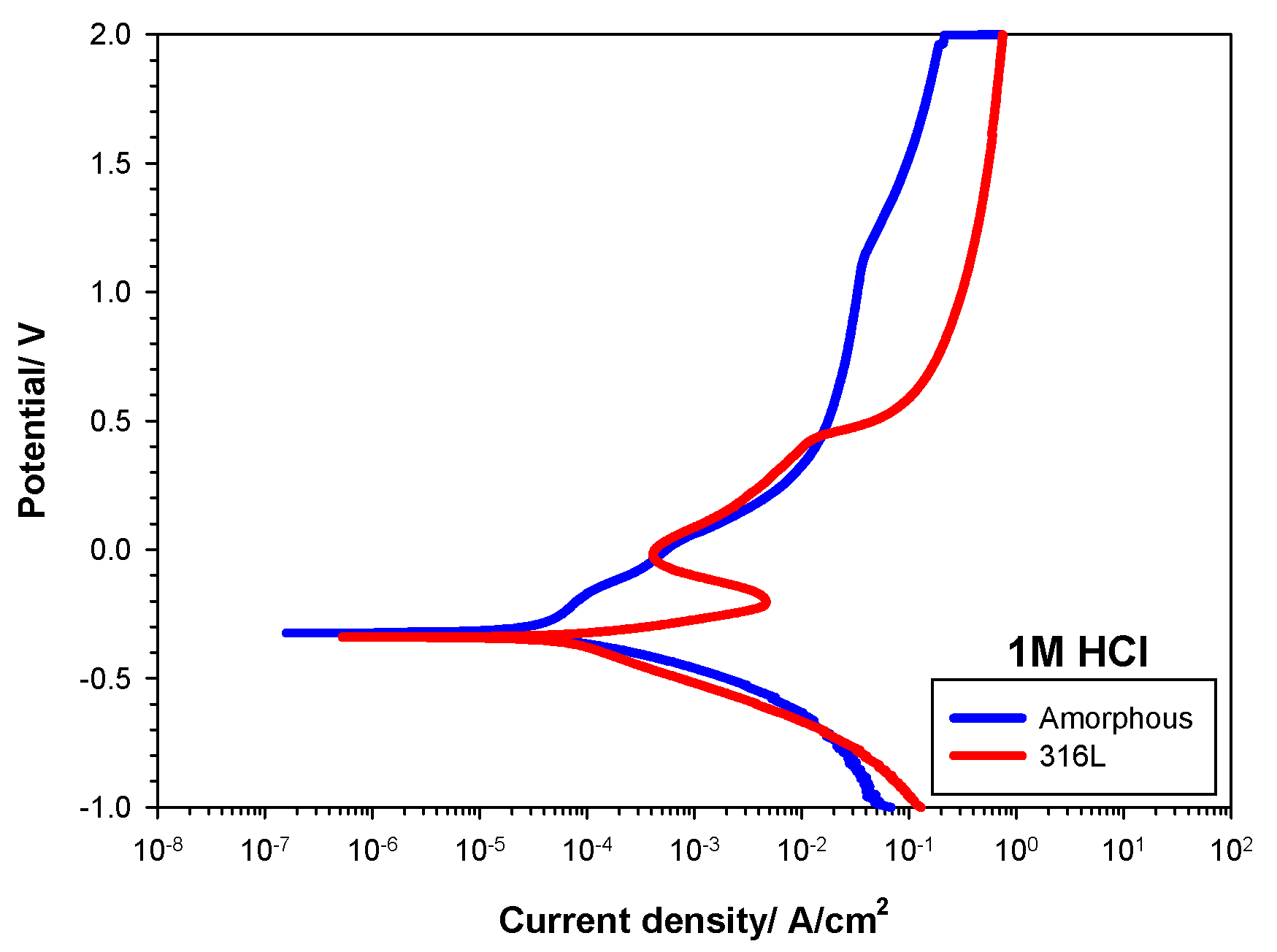
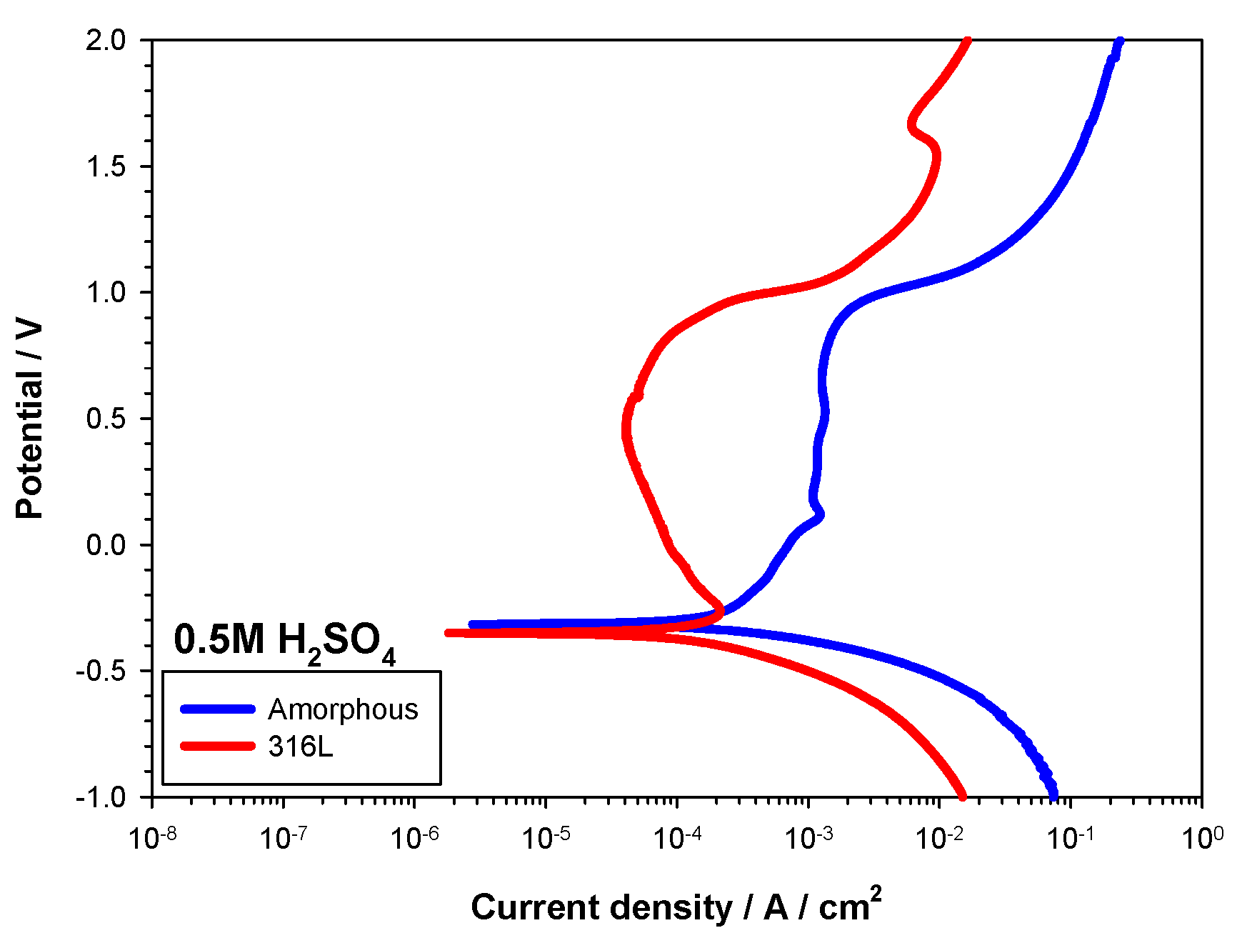
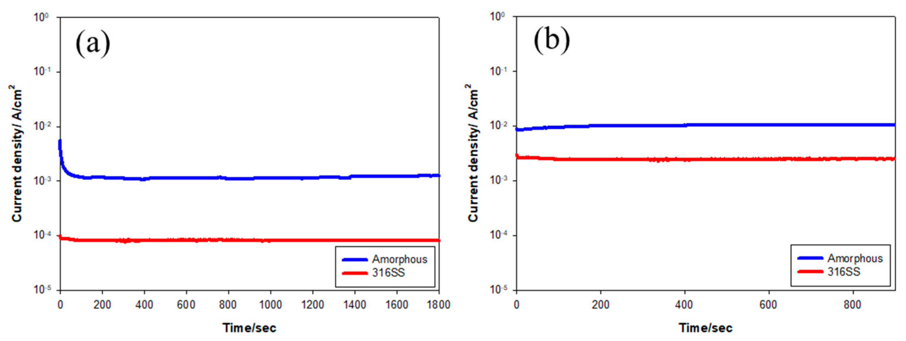
3.3. Corrosion Resistance of the 316L Substrate and the Coated Samples

The potentiodynamic polarization curves of the 316L substrate and an amorphous coated sample in distinct solutions are shown in Figure 4, Figure 5 and Figure 6. The corrosion potential (ECorr), corrosion current density (iCorr), and pitting potential (EPit) are listed in Table 1. Figure 4 shows the results of the potentiodynamic polarization tests for the samples tested in 3.5 wt.% NaCl solution. It indicated that the ECorr of both samples was about −0.55 V. The iCorr of the 316L substrate and the coating were about 3.96 and 4.70 μA/cm2, respectively. There was not much difference in ECorr and iCorr between the two samples tested in 3.5 wt.% NaCl solution. The pitting potential was determined at the inflection point of the polarization curve in the anodic side. As shown in Figure 4, the limited passive regions of the two tested samples implied a low ability to resist pitting corrosion in 3.5% NaCl solution. The EPit of the 316L substrate was about +0.10 V, with a value of −0.12 V for the coating. In addition, the passive current density of the 316L substrate was about one order smaller than that of the amorphous coating.
Figure 5 shows the potentiodynamic polarization curves of the samples tested in 1M HCl solution. The corrosion current densities of the tested samples in 1M HCl solution were much higher than those of the counterpart samples tested in 3.5 wt.% NaCl. The ECorr and iCorr of the 316L substrate were about −0.34 V and 58.2 μA/cm2, respectively. By contrast, those of the coating were about −0.29 V and 39.2 μA/cm2, accordingly. In harsh HCl solution, both samples showed lowered resistance to pitting corrosion and uniform corrosion. No passive zones in the polarization curves were found in both samples tested in 1M HCl solution. As shown in Figure 5, the EPit of the 316L substrate and the coating was about −0.08 V and −0.20 V, respectively. In addition, the corrosion current density of the coated sample was found to be smaller than that of the 316L substrate at an applied potential of −200 mV, which meant that the corrosion resistance of the coated sample would be higher than that of the 316L substrate.
The potentiodynamic polarization curves of the samples tested in 0.5 M H2SO4 solution are shown in Figure 6. The results showed marked passive regions in the two samples tested in such a mild acid. The ECorr and iCorr of the 316L substrate were −0.35 V and 55.0 μA/cm2, respectively. The ECorr and iCorr of the coated sample were −0.32 V and 62.0 μA/cm2. Moreover, the Epit of both samples was about 0.8 V, but the current density of the 316L substrate was obviously lower than that of the coating. The presence of a passive region in the polarization curve of the coating meant the formation of a protective film in 0.5M H2SO4 solution, but the high corrosion current density implied the occurrence of local corrosion.
Potentiostatic polarization tests at a constant applied potential were performed to confirm the change in corrosion current density with time, and the results are shown in Figure 7 and Figure 8. The chosen potentials were based on the potentiodynamic polarization curves shown in Figure 4 and Figure 6. In the 3.5% NaCl solution, the applied potential would be the open circuit potential (−500 mV), in the passivated zone (−200 mV), or near the transpassive dissolution range (+300 mV). As shown in Figure 7a, the coating had about the same current density (or corrosion rate) as the 316L substrate in 3.5% NaCl solution at −500 mV. Figure 7b showed that a drop in current density with increasing time occurred for the coated sample, which could be due to the gradual formation of protective film in the passivated zone (−200 mV). In 3.5% NaCl solution at +300 mV (Figure 7c), pitting corrosion resulted in an increase in the current densities of the tested samples with increasing time. It was noticed that the coating displayed slightly higher corrosion resistance than the 316L substrate in 3.5% NaCl solution at the applied potentials of −200 and +300 mV. By contrast, the 316L substrate had better corrosion resistance than the coating in the passivated (+500 mV) and transpassive dissolution (+1000 mV) states in 0.5 M H2SO4 solution (Figure 8). The results revealed that in 0.5 M H2SO4 solution, i.e., in mild acid, the corrosion resistance of the 316L substrate was superior to that of the amorphous coating, possibly due to the presence of defects in the latter.

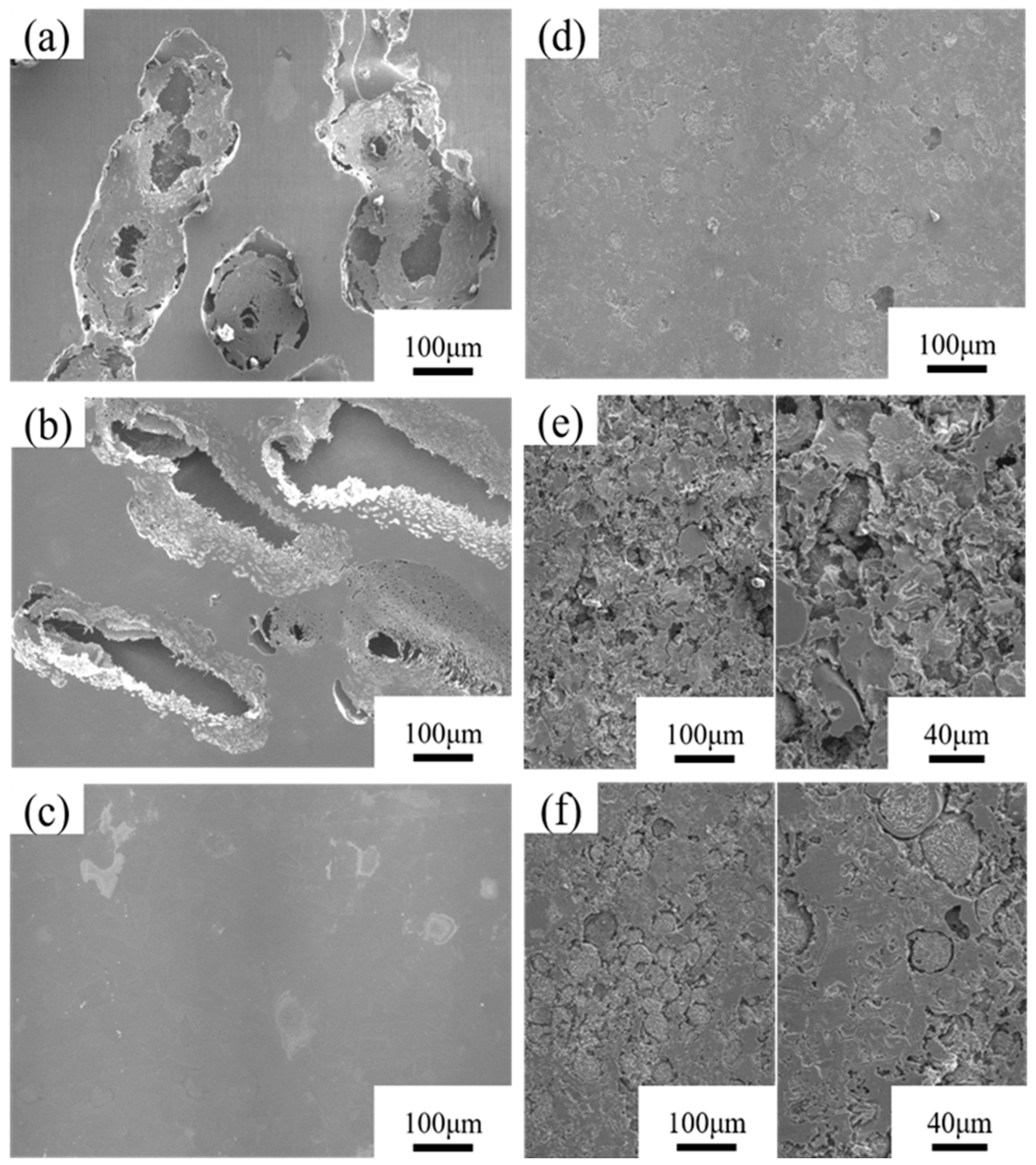
3.4. Surface Morphology of the Samples after Potentiodynamic Polarization Tests

The surface morphologies of the 316L substrate and the coating after potentiodynamic polarization tests are shown in Figure 9. After testing in 3.5% NaCl and 1 M HCl solutions, the 316L substrate exhibited clear corrosion damage due to the linkage of fine corrosion pits into large elongated pores (Figure 9a,b). The severe corrosion in 1 M HCl solution resulted in the formation of deep ditches and pores in the 316L substrate (Figure 9b). By contrast, only a few fine, shallow pits formed in the 316L substrate tested in 0.5M H2SO4 solution (Figure 9c). The potentiodynamic polarization curve of the 316L substrate also confirmed that the 0.5 M H2SO4 solution was a mild acid relative to the 3.5% NaCl and 1 M HCl solutions. The 316L substrate displayed high corrosion resistance in the 0.5 M H2SO4 solution. The corroded appearances of the coatings after potentiodynamic polarization tests are shown in Figure 9d–f. Overall, the corrosion features of the coatings in distinct solutions were quite different from those of the 316L substrate under the same testing conditions. Predominantly fine pits, which formed initially at the interface of residual powders and the molten zone, connected into fine ditches around the residual powders. Large corrosion pits or pores were not seen in the corroded coating, regardless of the testing solution. The results revealed that the amorphous coating had more capacity to resist uniform/pitting corrosion than the 316L substrate.

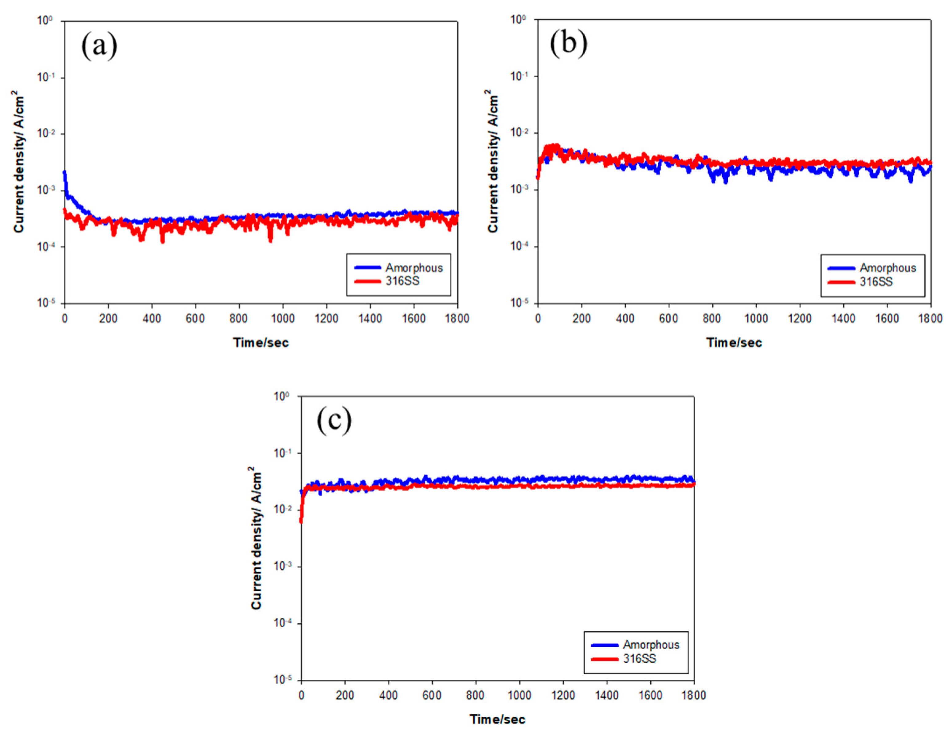
3.5. Corrosion-Wear in 3.5% NaCl Solution

With the applied potential and loading, corrosion-wear tests were performed to determine the wear resistance in 3.5% NaCl solution for the coating and the 316L substrate. Weight loss was the index used to evaluate the corrosion-wear resistance of the tested samples. Figure 10 shows the change in corrosion current density vs. time at a fixed load of 29.4 N at different potentials. Despite the different applied potentials, it was found that the corrosion current density of the coating was about the same as that of the 316L substrate and changed little with time. As compared with the potentiostatic polarization tests (Figure 7), the corrosion current density of the corrosion-wear samples was much higher than that of the samples without loading. At a potential of −500 mV, the corrosion current density would change from 6 × 10⁻⁶ A/cm2 to about 3 × 10⁻⁴ A/cm2 if an external load was applied. The same situation occurred when the potential was increased to −200 or +300 mV. Even at the passivated potential (−200 mV), the corrosion-wear current density could be as high as 3 × 10⁻³ A/cm2, which implied the disappearance of passivation or a high corrosion rate (Figure 10b). The rupture of the passivated film during contact wear was responsible for the increased corrosion rate. Increasing the potential also caused an increase in current density or corrosion rate in the corrosion-wear test (Figure 10c). Table 2 lists the weight loss of the corrosion-wear samples at distinct potentials. Increasing the potential caused increases in the weight loss of the tested samples. Moreover, the wear-corrosion tests showed that the samples with the amorphous coating had obviously low wear loss in 3.5%NaCl solution, as compared with the 316L substrate under the same testing conditions.

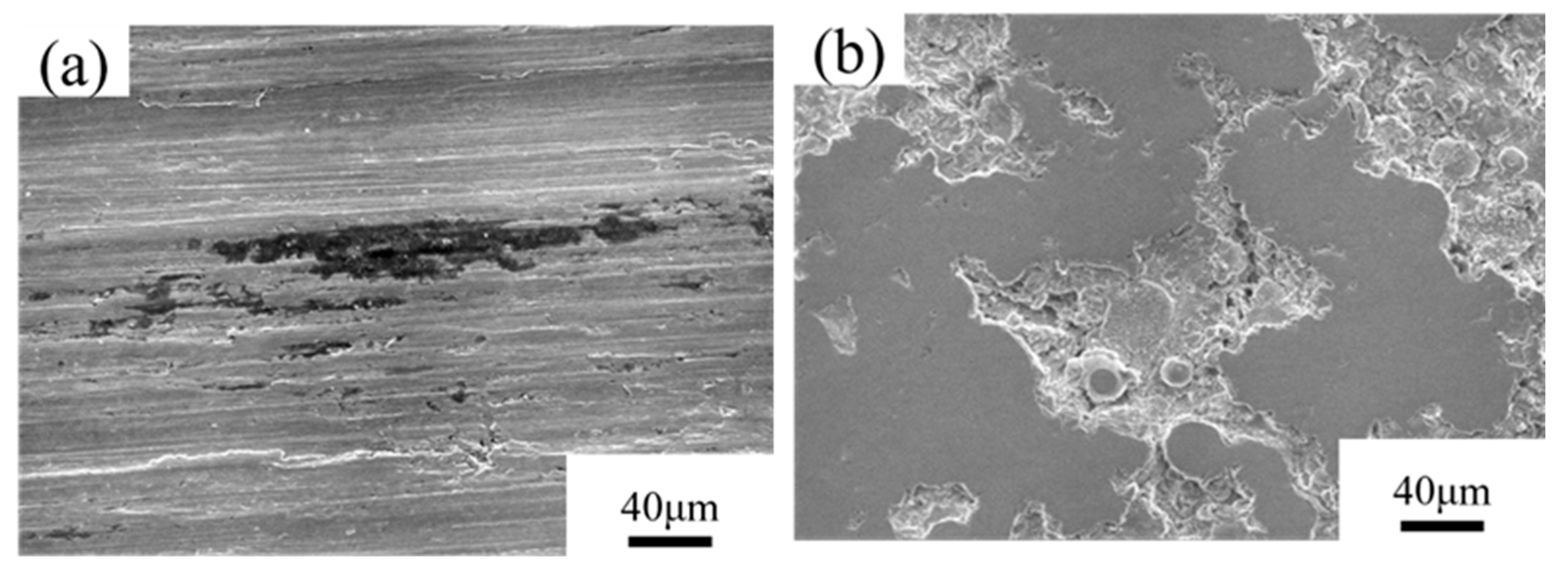
3.6. SEM Observations of the Samples after Corrosion-Wear Tests

Figure 11 exhibits the worn surface morphologies of the 316L substrate and amorphous coating after the wear-corrosion tests in 3.5%NaCl solution. It was found that the surface features of the tested sample changed little with increasing potential after the corrosion-wear test. Parallel plastic furrows were seen on the contact surface of the 316L substrate after the corrosion-wear tests (Figure 11a). This morphology was related to the micro-cutting mechanism. In addition, adhesive wear occurred in combination with micro-cutting. In contrast, no plastic furrows or adhesive wear were found on the contact surface of the amorphous coating after the tests (Figure 11b). A rubbed smooth surface and a corroded zone on the worn surface of the coating (Figure 11b) implied that corrosion-wear dominated the failure of the amorphous coating in the tests. In addition, the corrosion was more likely to initiate at and propagate along the defective sites such as fine voids and interfaces in the coating. According to the damaged surface morphology, the deep furrows were responsible for the greater weight loss of the 316L substrate in the corrosion-wear test. Undoubtedly, the amorphous coating was more resistant to corrosion-wear than the 316L substrate in 3.5%NaCl solution.

4. Discussion

The XRD pattern of the powder (Figure 2) consisted of a few sharp peaks, which could be associated with the complex alloy carbides, borides, and intermetallics, whereas no such precipitates or nanostructures were found in the amorphous coating (Figure 2). Therefore, the high cooling rate of the HVOF spraying enforced the formation of the amorphous phase in the coating. This developed FeCrNiMoCBSi powder had a sufficiently high glass-forming ability for thermal spray coating. In this work, the HVOF coating contained only very fine pinholes and microcracks/interfaces between the molten zone and partially melted powders (Figure 3). The micro-hardness of the as-deposited coating was above Hv 1120, which was obviously harder than conventional alloys. Therefore, the coating was expected to be able to provide high resistance to wear. In addition, the amorphous coating possessed a similar elastic constant as the conventional steel alloy.
In prior studies, the 316 coating fabricated by HVOF in seawater has shown corrosion resistance inferior to the 316 substrate [49,50]. The corrosion behavior of the 316 coating is affected by the porosity, unmelted particles, and micro- and macro-cracks [49,50]. Therefore, the defects present in the coating are expected to obviously deteriorate its corrosion resistance. The high uniform and pitting corrosion resistance of the amorphous alloys is attributed to their homogeneous structure, which lacks grain boundaries. The addition of Cr and Mo into the Fe-based amorphous coating assists in the formation of a passive surface film to increase corrosion resistance and passivity. [51]. Moreover, the corrosion resistance of a Fe-based amorphous coating in 3.5% NaCl solution is affected by the powder size [34], spraying power [52], and kerosene/oxygen flow rate [23]. The defective sites and interfaces between the unmelted powders and the molten zone in the amorphous coating are the preferential sites for corrosion [23,34]. It has been pointed out that the influence of porosities on the corrosion resistance of the coating has a long-lasting effect [53].
The potentiodynamic polarization curves showed that the coating had about the same corrosion rate as the 316L substrate in the 3.5% NaCl and 1 M HCl solutions. In 0.5M H2SO4 solution, the passive current density of the 316L substrate was lower and the passive range of the 316L substrate was wider than those of the coating. The results of potentiostatic polarization at a constant applied potential confirmed that the coating and the 316L substrate had about the same corrosion rate in the 3.5% NaCl solution, but that it was inferior to the 316L substrate in the 0.5 M H2SO4 solution. However, the corroded features of the coating were clearly different from those of the 316L substrate under the same testing conditions. Predominantly fine pits, which formed initially at the interface between partially melted powders and the molten zone, connected to form fine ditches around the residual powders. By contrast, large pores and deep ditches were observed in the corroded 316L substrate exposed to the 3.5% NaCl and 1M HCl solutions. It was obvious that the amorphous coating had higher resistance to uniform/pitting corrosion than the 316L substrate.
With applied potential and loading, the pin-on-ring tests were carried out to determine the corrosion-wear resistances of the coated sample and the 316L substrate in 3.5% NaCl solution. Despite different applied potentials, the corrosion current density of the coating was about the same as that of the 316L and changed little with time (Figure 10). When the potentiostatic polarization test was conducted with a constant applied potential, a great increase in current density at the same applied potential during the corrosion-wear test implied an obvious increase in the corrosion rate. Such events could be attributed to the continuous removal of passive film during contact wear. As listed in Table 2, the amorphous coating had an obviously low wear loss in 3.5%NaCl solution, as compared with the 316L counterpart tested under the same conditions. The worn surface morphology of the 316L substrate contained parallel plastic furrows formed on the contact surface of the 316L after the corrosion-wear tests (Figure 11a). By contrast, a rubbed smooth surface and a corroded zone were found on the worn surface of the coating (Figure 11b). The less damaged surface also confirmed that the coating had greater corrosion-wear resistance than the 316L substrate in 3.5%NaCl solution.
The corrosion resistance of Fe-based amorphous coatings is reported to be better than that of 304 but not far from that of 316 stainless steel [47]. Lee et al. [47] pointed out that the Fe40-Cr19-Mo18-C15-B8 alloy’s amorphous coating has a corrosion resistance equivalent to that of the 316 and is better than that of the 304. As mentioned previously in this work, the corrosion resistance of the coating will be affected by the alloy compositions and the original defects in the coating or the coating quality. It is reported that Ni-based coatings are also widely used in marine environments [53,54,55,56,57,58,59,60,61]. Referring to the open literature, the corrosion resistance and hardness of the investigated amorphous coating are compared to those of the Ni-based coatings, as listed in Table 3. The coating hardness of NiCr or NiCrBSi was in the range of Hv 570–Hv 660, which was lower than that of the Fe-based amorphous coating. In 3.5% NaCl solution or seawater, the potentiodynamic polarization tests of NiCr or NiCrBSi coatings show that the ECorr of the coating is in the range of −350 to −580 mV. However, a great variation in iCorr from 0.11 to 30 μA/cm2 is found for the distinct coatings, which can be attributed to the difference in compositions and the original defects in the as-deposited coating. Therefore, reducing the defects in the coating definitely improved the corrosion resistance of the coating.
Overall, the newly developed FeCrNiMoCBSi alloy system possessed a sufficiently high glass-forming ability and met the requirement as the feedstock for HVOF coating. The results of corrosion and corrosion-wear tests showed that the defective sites present in the amorphous coating obviously deteriorated its properties. To improve the resistance to wear and corrosion, the number of defects in the coating had to be reduced by optimizing the spray process parameters, remelting the coating to densify the surface layer [61], or applying other advanced spraying technologies. Therefore, the use of Fe-based glassy metals for coating will be an effective way to enhance the surface properties of structural components.

5. Summary

  • The FeCrNiMoCBSi alloy system has been developed and proposed as the feedstock for HVOF coating. The XRD spectra revealed that the feedstock powder possessed few carbides and borides, and no such precipitates were found in the amorphous coating. The micro-hardness of the as-deposited coating was above Hv 1120, and it was expected to provide high wear resistance.
  • In potentiodynamic and potentiostatic polarization tests, the coating and the 316L substrate had roughly the same corrosion rates in 3.5% NaCl and 1M HCl solutions. The corrosion resistance of the coating in the 0.5M H2SO4 solution was inferior to that of the 316L, which could be attributed to the presence of defects in the former. SEM features of the corroded samples revealed large pores and deep ditches in the 316L corroded in the 3.5% NaCl and 1 M HCl solutions, whereas predominantly fine ditches around the residual powders were observed in the corroded coating.
  • The corrosion-wear tests of the coating and the 316L substrate in 3.5% NaCl solution showed that the corrosion current densities of the two were about the same. For comparison with the counterpart samples in potentiostatic polarization tests, a large increase in corrosion current density during corrosion-wear tests at the same applied potential implied an obvious increase in corrosion rate. Such results were due to the continuous removal of the passive film of the samples during contact wear. The worn surface morphology of the 316L SS displayed parallel plastic furrows. In contrast, a rubbed smooth surface and corroded zone were found on the worn surface of the coating. The less damaged surface confirmed that the coating had greater corrosion-wear resistance than the 316L substrate in 3.5% NaCl solution.

Author Contributions

P.-H.L.: Investigation. J.-W.J.: Investigation, Writing—Review & Editing, Visualization. L.-W.T.: Conceptualization, Methodology, Resources, Writing—Original Draft, Supervision, Project administration, Funding acquisition. All authors have read and agreed to the published version of the manuscript.

Funding

This research was funded by the Ministry of Science and Technology, R.O.C., grant number MOST 109-2221-E-019-023-MY3 and MOST 110-2622-E-019-008.

Data Availability Statement

Data available on request due to restrictions, e.g., privacy or ethical.

Acknowledgments

The authors are grateful to the HT-DSC data from Thermal Analysis System of Instrumentation Center, National Taiwan University. Thank Precious Instrumentation Center at NTUST for Hysitron TI 980 TriboIndenter, Nanoindentation analysis.

Conflicts of Interest

The authors declare no conflict of interest.

References

  1. Kuroda, S.; Tashiro, Y.; Yumoto, H.; Taira, S.; Fukanuma, H.; Tobe, S. Peening action and residual stresses in high-velocity oxygen fuel thermal spraying of 316L stainless steel. J. Therm. Spray Tech. 2001, 10, 367–374. [Google Scholar] [CrossRef]
  2. Wang, Y.Y.; Li, C.J.; Ohmori, A. Influence of substrate roughness on the bonding mechanisms of high velocity oxy-fuel sprayed coatings. Thin Solid Films 2005, 485, 141–147. [Google Scholar] [CrossRef]
  3. Zhou, Z.; Wang, L.; He, D.Y.; Wang, F.C.; Liu, Y.B. Microstructure and Wear Resistance of Fe-Based Amorphous Metallic Coatings Prepared by HVOF Thermal Spraying. J. Therm. Spray Technol. 2010, 19, 1287–1293. [Google Scholar] [CrossRef]
  4. Oksa, M.; Turunen, E.; Suhonen, T.; Varis, T.; Hannula, S.P. Optimization and Characterization of High Velocity Oxy-fuel Sprayed Coatings: Techniques, Materials, and Applications. Coatings 2011, 1, 17–52. [Google Scholar] [CrossRef] [Green Version]
  5. Verdian, M.M.; Raeissi, K.; Salehi, M. Corrosion performance of HVOF and APS thermally sprayed NiTi intermetallic coatings in 3.5% NaCl solution. Corros. Sci. 2010, 52, 1052–1059. [Google Scholar] [CrossRef]
  6. Lindner, T.; Löbel, M.; Lampke, T. Phase Stability and Microstructure Evolution of Solution-Hardened 316L Powder Feedstock for Thermal Spraying. Metals 2018, 8, 1063. [Google Scholar] [CrossRef] [Green Version]
  7. Kutschmann, P.; Lindner, T.; Börner, K.; Reese, U.; Lampke, T. Effect of Adjusted Gas Nitriding Parameters on Microstructure and Wear Resistance of HVOF-Sprayed AISI 316L Coatings. Materials 2019, 12, 1760. [Google Scholar] [CrossRef] [PubMed] [Green Version]
  8. Brezinová, J.; Landová, M.; Guzanová, A.; Dulebová, Ľ.; Draganovská, D. Microstructure, wear behavior and corrosion resistance of WC-FeCrAl and WC-WB-Co coatings. Metals 2018, 8, 399. [Google Scholar] [CrossRef] [Green Version]
  9. Ksiazek, M.; Boron, L.; Tchorz, A. Study on the Microstructure, Mechanical Properties, and Erosive Wear Behavior of HVOF Sprayed Al2O3-15 wt.% TiO2 Coating with NiAl Interlayer on Al–Si Cast Alloy. Materials 2020, 13, 4122. [Google Scholar] [CrossRef]
  10. Berger, L.M.; Sempf, K.; Sohn, Y.J.; Vaßen, R. Influence of Feedstock Powder Modification by Heat Treatments on the Properties of APS-Sprayed Al2O3-40% TiO2 Coatings. J. Therm. Spray Technol. 2018, 27, 654–666. [Google Scholar] [CrossRef]
  11. Tantavisut, S.; Lohwongwatana, B.; Khamkongkaeo, A.; Tanavalee, A.; Tangpornprasert, P.; Ittiravivong, P. The novel toxic free titanium-based amorphous alloy for biomedical application. J. Mater. Res. 2018, 7, 248–253. [Google Scholar] [CrossRef]
  12. Kuball, A.; Gross, O.; Bochtler, B.; Adam, B.; Ruschel, L.; Zamanzade, M.; Busch, R. Development and characterization of titanium-based bulk metallic glasses. J. Alloys Compd. 2019, 790, 337–346. [Google Scholar] [CrossRef]
  13. Inoue, A.; Yokoyama, Y.; Shinohara, Y.; Masumoto, T. Preparation of Bulky Zr-Based Amorphous Alloys by a Zone Melting Method. Mater. Trans. 1994, 35, 923–926. [Google Scholar] [CrossRef] [Green Version]
  14. Wang, F.; Yin, D.; Lv, J.; Zhang, S.; Ma, M.; Zhang, X.; Liu, R. Effect on microstructure and plastic deformation behavior of a Zr-based amorphous alloy by cooling rate control. J. Mater. Sci. Technol. 2021, 82, 1–9. [Google Scholar] [CrossRef]
  15. Xu, D.; Duan, G.; Johnson, W.L.; Garland, C. Formation and properties of new Ni-based amorphous alloys with critical casting thickness up to 5 mm. Acta Mater. 2004, 52, 3493–3497. [Google Scholar] [CrossRef]
  16. Wang, A.P.; Chang, X.C.; Hou, W.L.; Wang, J.Q. Corrosion behavior of Ni-based amorphous alloys and their crystalline counterparts. Corros. Sci. 2007, 49, 2628–2635. [Google Scholar] [CrossRef]
  17. Otsubo, F.; Kishitake, K. Corrosion Resistance of Fe-16%Cr-30%Mo-(C,B,P) Amorphous Coatings Sprayed by HVOF and APS Processes. Mater. Trans. 2005, 46, 80–83. [Google Scholar] [CrossRef] [Green Version]
  18. Huang, D.; Li, R.; Huang, L.; Ji, V.; Zhang, T. Fretting wear behavior of bulk amorphous steel. Intermetallics 2011, 19, 1385–1389. [Google Scholar] [CrossRef]
  19. Suryanarayana, C.; Inoue, A. Iron-based bulk metallic glasses. Int. Mater. Rev. 2013, 58, 131–166. [Google Scholar] [CrossRef]
  20. Souza, C.A.C.; Ribeiro, D.V.; Kiminami, C.S. Corrosion resistance of Fe–Cr-based amorphous alloys: An overview. J. Non Cryst. Solids 2016, 442, 56–65. [Google Scholar] [CrossRef]
  21. Kobayashi, A.; Yano, S.; Kimura, H.; Inoue, A. Mechanical property of Fe-base metallic glass coating formed by gas tunnel type plasma spraying. Surf. Coat. Technol. 2008, 202, 2513–2518. [Google Scholar] [CrossRef]
  22. Liu, X.Q.; Zheng, Y.G.; Chang, X.C.; Hou, W.L.; Wang, J.Q.; Tang, Z.; Burgess, A. Microstructure and properties of Fe-based amorphous metallic coating produced by high velocity axial plasma spraying. J. Alloys Compd. 2009, 484, 300–307. [Google Scholar] [CrossRef]
  23. Zhou, Z.; Wang, L.; Wang, F.C.; Zhang, H.F.; Liu, Y.B.; Xu, S.H. Formation and corrosion behavior of Fe-based amorphous metallic coatings by HVOF thermal spraying. Surf. Coat. Technol. 2009, 204, 563–570. [Google Scholar] [CrossRef]
  24. Zhang, C.; Liu, L.; Chan, K.C.; Chen, Q.; Tany, C.Y. Wear behavior of HVOF-sprayed Fe-based amorphous coatings. Intermetallics 2012, 29, 80–85. [Google Scholar] [CrossRef]
  25. Wang, Y.; Zheng, Y.G.; Ke, W.; Sun, W.H.; Hou, W.L.; Chang, X.C.; Wang, J.Q. Slurry erosion–corrosion behaviour of high-velocity oxy-fuel (HVOF) sprayed Fe-based amorphous metallic coatings for marine pump in sand-containing NaCl solutions. Corros. Sci. 2011, 53, 3177–3185. [Google Scholar] [CrossRef]
  26. Huang, Y.; Guo, Y.; Fan, H.; Shen, J. Synthesis of Fe–Cr–Mo–C–B amorphous coating with high corrosion resistance. Mater. Lett. 2012, 89, 229–232. [Google Scholar] [CrossRef]
  27. Wang, Y.; Zheng, Y.G.; Ke, W.; Sun, W.H.; Wang, J.Q. Corrosion of high-velocity oxy-fuel (HVOF) sprayed iron-based amorphous metallic coatings for marine pump in sodium chloride solutions. Mater. Corros. 2011, 63, 685–694. [Google Scholar] [CrossRef]
  28. Qiao, L.; Wu, Y.; Hong, S.; Zhang, J.; Shi, W.; Zheng, Y. Relationships between spray parameters, microstructures and ultrasonic cavitation erosion behavior of HVOF sprayed Fe-based amorphous/nanocrystalline coatings. Ultrason. Sonochem. 2017, 39, 39–46. [Google Scholar] [CrossRef] [PubMed]
  29. Tului, M.; Bartuli, C.; Bezzon, A.; Marino, A.L.; Marra, F.; Matera, S.; Pulci, G. Amorphous Steel Coatings Deposited by Cold-Gas Spraying. Metals 2019, 9, 678. [Google Scholar] [CrossRef] [Green Version]
  30. Ni, H.S.; Liu, X.H.; Chang, X.C.; Hou, W.L.; Liu, W.; Wang, J.Q. High performance amorphous steel coating prepared by HVOF thermal spraying. J. Alloys Compd. 2009, 467, 163–167. [Google Scholar] [CrossRef]
  31. Xie, L.; Wang, Y.M.; Xiong, X.; Chen, Z.K. Comparison of Microstructure and Tribological Properties of Plasma, High Velocity Oxy-Fuel and Detonation Sprayed Coatings from an Iron-Based Powder. Mater. Trans. 2018, 59, 1591–1595. [Google Scholar] [CrossRef] [Green Version]
  32. Zhang, H.; Hu, Y.; Hou, G.; An, Y.; Liu, G. The effect of high-velocity oxy-fuel spraying parameters on microstructure, corrosion and wear resistance of Fe-based metallic glass coatings. J. Non Cryst. Solids 2014, 406, 37–44. [Google Scholar] [CrossRef]
  33. Peng, Y.; Zhang, C.; Zhou, H.; Liu, L. On the bonding strength in thermally sprayed Fe-based amorphous coatings. Surf. Coat. Technol. 2013, 218, 17–22. [Google Scholar] [CrossRef]
  34. Zhang, C.; Guo, R.Q.; Yang, Y.; Wu, Y.; Liu, L. Influence of the size of spraying powders on the microstructure and corrosion resistance of Fe-based amorphous coating. Electrochim. Acta 2011, 56, 6380–6388. [Google Scholar] [CrossRef]
  35. Xie, L.; Xiong, X.; Zeng, Y.; Wang, Y. The wear properties and mechanism of detonation sprayed iron-based amorphous coating. Surf. Coat. Technol. 2019, 366, 146–155. [Google Scholar] [CrossRef]
  36. Wang, G.; Xiao, P.; Huang, Z.J.; He, R.J. Microstructure and Wear Properties of Fe-based Amorphous Coatings Deposited by High-velocity Oxygen Fuel Spraying. J. Iron Steel Res. Int. 2016, 23, 699–704. [Google Scholar] [CrossRef]
  37. Bakare, M.S.; Voisey, K.T.; Chokethawai, K.; McCartney, D.G. Corrosion behaviour of crystalline and amorphous forms of the glass forming alloy Fe43Cr16Mo16C15B10. J. Alloys Compd. 2012, 527, 210–218. [Google Scholar] [CrossRef] [Green Version]
  38. Pang, S.J.; Zhang, T.; Asami, K.; Inoue, A. New Fe–Cr–Mo–(Nb, Ta)–C–B Glassy Alloys with High Glass-Forming Ability and Good Corrosion Resistance. Mater. Trans. 2001, 42, 376–379. [Google Scholar] [CrossRef] [Green Version]
  39. Pang, S.J.; Zhang, T.; Asami, K.; Inoue, A. Synthesis of Fe–Cr–Mo–C–B–P bulk metallic glasses with high corrosion resistance. Acta Mater. 2002, 50, 489–497. [Google Scholar] [CrossRef]
  40. Pang, S.J.; Zhang, T.; Asami, K.; Inoue, A. Bulk glassy Fe–Cr–Mo–C–B alloys with high corrosion resistance. Corros. Sci. 2002, 44, 1847–1856. [Google Scholar] [CrossRef]
  41. Shen, J.; Chen, Q.; Sun, J.; Fan, H.; Wang, G. Exceptionally high glass-forming ability of an FeCoCrMoCBY alloy. Appl. Phys. Lett. 2005, 86, 151907. [Google Scholar] [CrossRef]
  42. Amiya, K.; Inoue, A. Fe–(Cr, Mo)–(C, B)–Tm Bulk Metallic Glasses with High Strength and High Glass-Forming Ability. Mater. Trans. 2006, 47, 1615–1618. [Google Scholar] [CrossRef] [Green Version]
  43. Hirata, A.; Hirotsu, Y.; Amiya, K.; Inoue, A. Crystallization process and glass stability of an Fe48Cr15Mo14C15B6Tm2 bulk metallic glass. Phys. Rev. B 2008, 78, 144205. [Google Scholar] [CrossRef]
  44. Kumar, A.; Kumar, R.; Bijalwab, P.; Dutta, M.; Banerjee, A.; Laha, T. Fe-based amorphous/nanocrystalline composite coating by plasma spraying: Effect of heat input on morphology, phase evolution and mechanical properties. J. Alloys Compd. 2019, 771, 827–837. [Google Scholar] [CrossRef]
  45. Pan, T.J.; Leng, Y.; Liu, S.; Jiang, J.; Shen, J.; Xiang, J.H. Wear and Corrosion Resistance Performance of Iron-Based Metallic Amorphous Coating Produced by Twin Wire Arc Spraying. J. Mater. Eng. Perform. 2022. [Google Scholar] [CrossRef]
  46. Iqbal, A.; Iqbal, A.; Moskal, G.; Yasir, M.; Al-Mansour, A.I.; Khan, M.A.; Alam, S.; Shahbaz, M.; Zia, A.; Ejaz, A. Long-Term Potentiodynamic Testing and Tribometric Properties of Amorphous Alloy Coatings under Saline Environment. Molecules 2022, 27, 1421. [Google Scholar] [CrossRef] [PubMed]
  47. Lee, H.B.; Lin, T.J.; Lee, C.Y. Corrosion of High-Velocity-Oxygen-Fuel (HVOF) Sprayed Non-crystalline Alloy Coating in Marine Environment. Surf. Coat. Technol. 2021, 409, 126896. [Google Scholar] [CrossRef]
  48. Soboley, V.V.; Guilemany, J.M. Investigation of coating porosity formation during high velocith oxy-fuel (HVOF) spraying. Mats. Lett. 1994, 18, 304–305. [Google Scholar] [CrossRef]
  49. Suegama, P.H.; Fugivara, C.S.; Benedetti, A.V.; Fernandez, J.; Delgado, J.; Guilemany, J.M. Electrochemical behavior of thermally sprayed stainless steel coatings in 3.4% NaCl solution. Corros. Sci. 2005, 47, 605–620. [Google Scholar] [CrossRef]
  50. Kawakita, J.; Fukushima, T.; Kuroda, S.; Kodama, T. Corrosion behavior of HVOF sprayed SUS316 stainless steel in seawater. Corros. Sci. 2002, 44, 2561–2581. [Google Scholar] [CrossRef]
  51. Ning, W.C.; Zhai, H.M.; Xiao, R.Z.; He, D.G.; Liang, G.; Wu, Y.R.; Li, W.S.; Li, X.Q. The corrosion resistance mechanism of Fe-based amorphous coatings synthesized by detonation gun spraying. J. Mater. Eng. Perf. 2020, 29, 3921–3929. [Google Scholar] [CrossRef]
  52. Zhang, C.; Chu, Z.; Wei, F.; Qin, W.; Yang, Y.; Dong, Y.; Huang, D.; Wang, L. Optimazing process and the properties of the sprayed Fe-based metallic glassy coating by plasma spraying. Surf. Coat. Technol. 2017, 319, 1–5. [Google Scholar] [CrossRef]
  53. Zhao, W.M.; Wang, Y.; Han, T.; Wu, K.Y.; Xue, J. Electrochemical evaluation of corrosion resistance of NiCrBSi coatings deposited by HVOF. Surf. Coat. Technol. 2004, 183, 118–125. [Google Scholar] [CrossRef]
  54. Li, Y.J.; Dong, T.S.; Fu, B.G.; Li, G.L.; Liu, Q. Study of the Microstructure and Properties of Cold Sprayed NiCr Coating. J. Mater. Eng. Perform. 2021, 30, 9067–9077. [Google Scholar] [CrossRef]
  55. Wang, K.; Hong, S.; Wei, Z.; Hu, N.; Cheng, J.; Wu, Y. Long-term corrosion behavior of HVOF sprayed Cr3C2-NiCr coatings in sulfide-containing 3.5 wt.% NaCl solution. J. Mater. Res. Technol. 2021, 15, 3122–3132. [Google Scholar] [CrossRef]
  56. Tabatabaei, F.S.K.; Ghasemi, B.; Mirzaee, O.; Azadi, M.; Tabatabaei, S.S.K. An Investigation on Microstructural and Electrochemical Characteristics of NiCrBSi/WCCoCr Composite Coatings in 3.5 wt.% NaCl Solution. J. Mater. Eng. Perform. 2023. [Google Scholar] [CrossRef]
  57. Xiao, J.K.; Wu, Y.Q.; Zhang, W.; Chen, J.; Wei, X.L.; Zhang, C. Microstructure, wear and corrosion behaviors of plasma sprayed NiCrBSi-Zr coating. Surf. Coat. Technol. 2019, 360, 172–180. [Google Scholar] [CrossRef]
  58. Li, G.; Yang, X.; Guo, J.; Wu, Y.; Wang, X.; Zhang, J. Study on Corrosion Resistance and Mechanism of NiCrBSiFeCoC Coating in 3.5 wt% NaCl Solution. Trans. Indian Inst. Met. 2017, 70, 2213–2219. [Google Scholar] [CrossRef]
  59. Lee, H.B.; Hong, Y.H.; Sheu, H.H.; Hsiao, R.C.; Li, W.K.; Lin, H.E. Effects of Cr contents on tribological and corrosion behavior of HVOF sprayed Ni-based alloy coating. Tribol. Int. 2023, 183, 108384. [Google Scholar] [CrossRef]
  60. Ho, K.C.; Sheu, H.H.; Chang, J.K.; Lin, H.E.; Lee, Y.W.; Hsiao, P.S.; Lee, H.B.; Li, W.K. Study on the corrosion-wear behavior of Ni67.57Cr15.59Fe2.83C0.6Si3.98B3.47O0.045Mo2.97Co2.94 nickel alloy coating prepared by high velocity oxygen fuel spraying. Mater. Corros. 2023; ahead of print. [Google Scholar] [CrossRef]
  61. Zhao, W.M.; Wang, Y.; Dong, L.X.; Wu, K.Y.; Xue, J. Corrosion mechanism of NiCrBSi coatings deposited by HVOF. Surf. Coat. Technol. 2005, 190, 293–298. [Google Scholar] [CrossRef]
Figure 1. (a) The external morphology of the feedstock powder, (b) the cross-sectional view with hardness indentation of the powder and (c) the differential scanning calorimeter (DSC) curves of the feedstock powder.
Metals 13 01137 g001
Figure 2. X-ray diffractometer (XRD) spectra of (a) the feedstock powder and (b) the coating.
Metals 13 01137 g002
Figure 3. SEM images showing (a) the top and (b,c) cross-sectional views of the amorphous coating, and (d) the nano-indentation sites of the coating.
Metals 13 01137 g003
Figure 4. The potentiodynamic polarization curves of the 316L substrate and the amorphous coating in 3.5 wt.% NaCl solution.
Metals 13 01137 g004
Figure 5. The potentiodynamic polarization curves of the 316L substrate and the amorphous coating in 1M HCl solution.
Metals 13 01137 g005
Figure 6. The potentiodynamic polarization curves of the 316L substrate and the amorphous coating in 0.5M H2SO4 solution.
Metals 13 01137 g006
Figure 7. The change in corrosion current density with time in 3.5% NaCl solution at a constant potential: (a) −500 mV, (b) −200 mV and (c) +300 mV.
Metals 13 01137 g007
Figure 8. The change in corrosion current density with time in 0.5M H2SO4 solution at a constant potential: (a) +500 mV and (b) +1000 mV.
Metals 13 01137 g008
Figure 9. The typical surface morphologies of (ac) the 316L substrate and (df) the coating after potentiodynamic polarization tests. (a,d) in 3.5% NaCl; (b,e) in 1M HCl; (c,f) in 0.5M H2SO4 solutions.
Metals 13 01137 g009
Figure 10. The change in the corrosion current density vs. time at a fixed load of 29.4 N at (a) −500 mV, (b) −200 mV, and (c) +300 mV.
Metals 13 01137 g010
Figure 11. The worn surface morphologies of the (a) 316 substrate and (b) amorphous coating after the corrosion-wear tests.
Metals 13 01137 g011
Table 1. The ECorr, iCorr, and EPit of the coating and the 316L substrate tested in distinct solutions.
SampleCorrosion
Propertiesy
Testing Solution
3.5% NaCl1M HCl0.5M H2SO4
316LECorr (V)−0.55−0.34−0.35
iCorr (μA/cm2)3.9658.255.0
EPit (V)+0.10−0.08+0.80
CoatingECorr (V)−0.55−0.29−0.32
iCorr (μA/cm2)4.7039.262.0
EPit (V)−0.12−0.20+0.88
Table 2. The weight loss of the corrosion-wear samples in 3.5% NaCl solution at distinct potentials.
Weight Loss (mg)−500 mV−200 mV+300 mV
Sample
316L5292106
Coating81622
Table 3. The ECorr (vs. SCE), iCorr, and micro-vickers hardness of different coatings.
SamplesProperties
ECorr (mV)iCorr (μA/cm2) Hardness (Hv)
NiCr [54]−3971.08574
NiCr-Cr3C2 [55]−51518.98-*
NiCrBSi [53]−3506.95-
NiCrBSi [56]−4990.11-
NiCrBSi [57]−5654.31 600
NiCrBSi [58]−3900.91-*
NiCrBSi [59]−58030650**
NiCrBSiFeMoCo [60]−49018660**
Fe-amorphous−5504.701120
* polarization test after 1 day immersion in 3.5% NaCl solution. ** polarization test in seawater, other referenced results are tested in 3.5% NaCl solution.
Disclaimer/Publisher’s Note: The statements, opinions and data contained in all publications are solely those of the individual author(s) and contributor(s) and not of MDPI and/or the editor(s). MDPI and/or the editor(s) disclaim responsibility for any injury to people or property resulting from any ideas, methods, instructions or products referred to in the content.

