Article

Ductile Fracture Behavior of ASTM A516 Gr.70 Pressure Vessel Steel by ASTM and ISO Fracture Toughness Standards

by
Gabriel de Castro Coêlho
1,
Antonio Almeida Silva
2,
Marco Antonio dos Santos
2,
José J. M. Machado
3 and
João Manuel R. S. Tavares
3,*
1
Graduate Program of Materials Science and Engineering, Federal University of Campina Grande, Campina Grande 58429-900, Brazil
2
Department of Mechanical Engineering, Federal University of Campina Grande, Campina Grande 58429-900, Brazil
3
Instituto de Ciência e Inovação em Engenharia Mecânica e Engenharia Industrial, Departamento de Engenharia Mecânica, Faculdade de Engenharia, Universidade do Porto, Rua Dr. Roberto Frias s/n, 4200-465 Porto, Portugal
*
Author to whom correspondence should be addressed.
Metals 2023, 13(5), 867; https://doi.org/10.3390/met13050867
Submission received: 8 April 2023 / Revised: 26 April 2023 / Accepted: 27 April 2023 / Published: 29 April 2023
(This article belongs to the Special Issue Advances in Nuclear Reactor Pressure Vessel Steels)

Abstract

:
Fracture toughness determination is crucial for the design phase of pressure vessels, and, although ASTM E1820 and ISO 12135 fracture toughness standards have existed for some time, some differences have been reported in the determination of this property. This study investigates the ductile fracture behavior of ASTM A516 Gr.70 pressure vessel steel and assesses the differences in estimating both standards. The steel’s tensile properties and initiation fracture toughness (JIC) were evaluated, taking into account the parallel and perpendicular orientations to the rolling direction. The results reveal the properties’ dependence on the rolling direction, mainly attributed to perlite banding. Additionally, as for the JIC determination, the differences were associated with the different blunting line slope estimations on each standard, reinforcing the necessity of a work-hardening-based blunting line for each material assessed.

1. Introduction

Pressure vessels are process equipment designed to contain determined fluids under specified internal pressure and temperature. These structures withstand severe operational regimes during which damage may occur, leading to their catastrophic failure. Among several damage types, a fracture is one of the most difficult to prevent once crack-like flaws initiate their growth along some direction on the structure. Naturally, a material’s property translates its resistance to a crack advance and plays an important role in material selection during a pressure vessel, or any other engineering structure, design phase. This property is known as fracture toughness, and its estimation is vital for the engineering design phase since pressure vessels’ design routines are based either on the ‘yield-before-break’ (YBB) or ‘leak-before-break’ (LBB) criterion for the sake of safety. Small pressure vessels are designed so a significant amount of plastic deformation, triggered by slight internal pressure, precedes unstable crack growth, a criterion known as YBB [1,2,3]. Therefore, materials with high fracture toughness-to-yield stress ratio ( K c σ Y S ) are preferred. On the other hand, for larger pressure vessels, this might not be possible to achieve, leaving designers with the option to allow the crack to stably grow until it reaches full thickness depth, accepting some leakage to occur, a criterion known as LBB [1,4,5]. In this case, materials having high K c 2 σ Y S ratio are preferred.
Typically, pressure vessel steels exhibit elastic–plastic behavior and high toughness, requiring the assessment of their fracture toughness using the J-Integral or crack tip opening displacement (CTOD) method by deriving the materials’ resistance curve. Worldwide commonly accepted standards for fracture toughness measurement are the ASTM 1820 [6] and the ISO 12135 standards [7]. Despite existing for quite some time, those standards have produced differences in determining the fracture toughness [8,9,10,11], with blunting (or construction) line slope, exclusion lines’ distance, and fitting equations pointed out as the main reasons for the found differences.
The blunting line defines the crack advance due to the blunt of the original sharp crack front [12,13,14,15], specifically the crack front displacement due to elastic–plastic deformation. For ASTM 1820 [6], the blunting line is given by:
δ = 1.4 Δ a ,
And, for ISO 12135 [7], it is given by:
δ = 1.87 ( σ U S σ Y S ) Δ a ,
where δ is the CTOD and σ Y S and σ U S are the materials’ yield and ultimate strength, respectively. Equation (1) was derived under the consideration of an elastic–perfect plastic material whose crack front should be blunt in a semicircular shape [16], while Equation (2) was derived under the supposition of a power law tensile material behavior [12]. Both standards base their fracture toughness determination methodology on using an arbitrary offset line to the blunting line with the same slope, justified by the fact that stable tearing does not initiate simultaneously along the entire crack front [9,17].
The exclusion lines are plotted with the same slope as the blunting line and are used to ensure that enough data points are available for the fitting procedure of the resistance curve, especially for lower δ Δ a points. According to ASTM E1820 [6], at least one point should lie between 0.15 and 0.5 mm of the exclusion lines, and at least another point should lie between 0.5 and 1.5 mm of the exclusion lines. On the other hand, ISO 12135 [7] establishes that at least one point should lie between the 0.1 mm and the 0.3 mm exclusion lines and at least two points between 0.1 mm and 0.5 mm of the exclusion lines.
The fitting equations are power law equations given as:
δ = C 1 Δ a C 2 ,
for ASTM E1820 [6] and
δ = α + β Δ a γ ,
for ISO 12135 [7]. These fittings are performed to estimate the initiation fracture toughness (JIC) with enough data.
Landes [8] used J-Integral resistance curves to conclude that the slope difference of the blunting line of both standards should be re-evaluated as this difference was responsible for the determined scattered JIC values; namely, the ISO 12135 [7] blunting line slope was twice as large as the ASTM 1820 [6] blunting line slope. Regarding the fitting equations, Landes [8] also stated that both equations yield almost the same behavior. Arora and Viehrig [9] also determined the influence of the blunting line slope yielding on the different fracture toughness values and pointed out the lower exclusion line of ISO 12135 [7] on estimating lower fracture toughness values. Khandelwal et al. [10] also assessed the significant influence of the blunting line slope on the estimation of JIC, and, in their study, the ISO 12135 [7] blunting line slope was almost twice the value obtained with ASTM 1820 [6], although they attributed no influence of the fitting equations to it. Li et al. [11] drew the same conclusions as Khandelwal et al. [10] and recognized the differences in the considerations for the material’s behavior during the derivation of Equations (3) and (4).
The inconsistency of the methodology to determine JIC is still an aspect to be explored. The primary purpose of this study was to investigate the ductile fracture behavior of the ASTM A516 Gr.70 pressure vessel steel and assess the differences in the estimation of the ASTM 1820 [6] and ISO 12135 [7] fracture toughness standards.

2. Materials and Methods

ASTM A516 Gr.70 is a structural steel recommended for constructing pressure vessels with applications in moderate-to-low temperatures, and it is supplied as hot-rolled with no post-heat treatment normalization for plates up to 25 mm thickness. The experimental analysis consisted of metallographic analysis for microstructural characterization, tensile tests, and fracture toughness tests at room temperature.

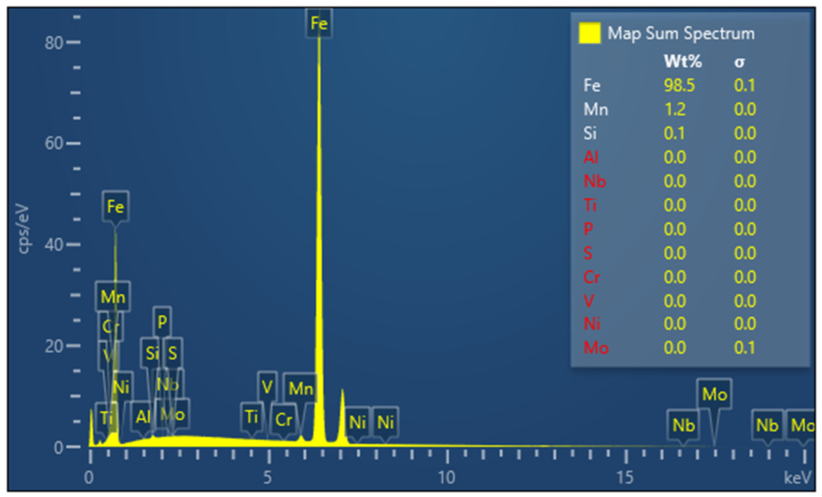
2.1. Chemical Composition

To confirm the ASTM A516 Gr.70 chemical composition, an energy-dispersive spectroscopy (EDS) analysis was performed, which led to the spectrum shown in Figure 1, which confirmed that the materials follow the chemical composition according to the current standard [18]. From the obtained values, the carbon content (C) was found to be 0.20%.

2.2. Metallographic Analysis
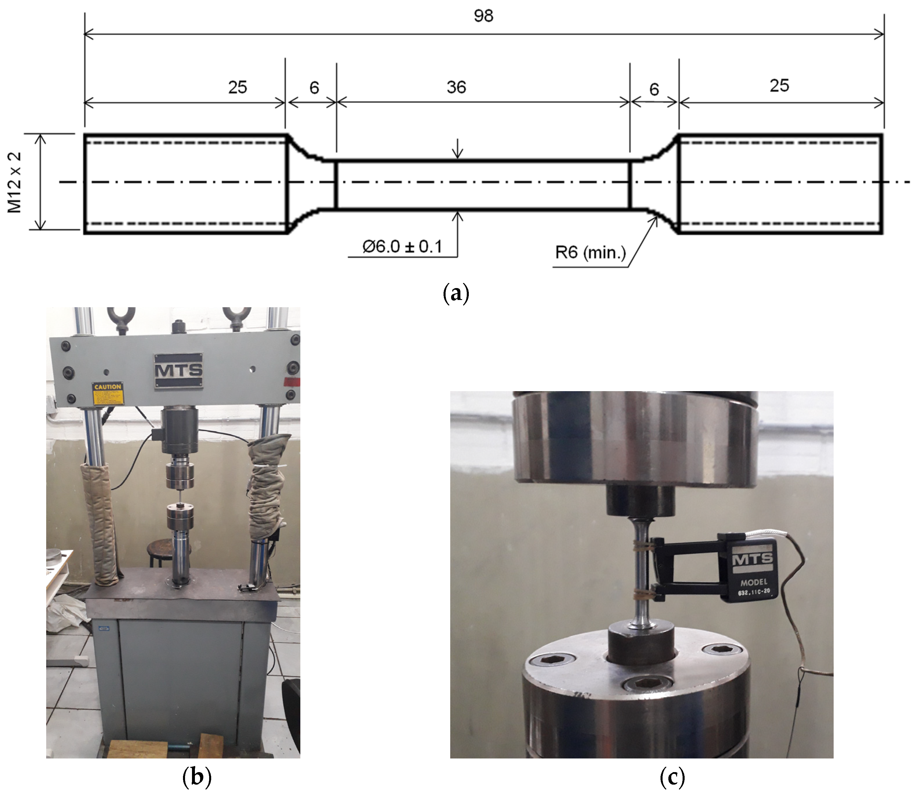
This analysis followed the recommendations of the ASTM E3 [19] standard. The metallographic samples were cut with approximately 13 mm × 13 mm × 12.7 mm (superficial area of 169 mm2) on the rolling direction (RD) and along the plate thickness. The samples were embedded on Bakelite and then grinded with wet sandpaper (200, 320, 400, 600, 800, and 1200 grit). Then, they were mechanically polished with alumina (particle sizes of 1 (one), 0.5, and 0.3 μm) so the inclusions could be observed by optical microscopy. Subsequently, the samples were etched with 5% Nital (5 mL HNO3 + 95 mL ethylic alcohol) by immersion for a few seconds, as recommended by ASTM E407 [20], and the microstructure of the material was observed.
The ASTM grain size was estimated according to the ASTM E112-13 [21] standard by the intersection technique, where the number crossing ( N L ) of a group of lines (total length of L defined at the micrograph scale) with grain boundaries is counted, and the mean linear intersection ( l ) is calculated as l = L N L . Following, the ASTM grain size is estimated as:
G = ( 6.65 l ) 3.29 ,
where l is given in mm.

2.3. Tensile Test

The tensile tests were conducted according to the ASTM E8/E8M [22] standard. Firstly, twelve specimens were machined according to the dimensions shown in Figure 2a, and it is important to mention that six specimens had their gauge length parallel to the rolling direction and the other six perpendicularly. The tests were performed on an MTS 810 servo-hydraulic universal testing machine with a 100 kN load cell capacity, which is depicted in Figure 2b. As an example, one of the specimens assembled on the testing machine is shown in Figure 2c. The load vs. displacement (PL) and the final diameter were measured, so the engineering stress vs. strain curve and tensile properties, such as Young’s modulus, yield stress, ultimate stress, rupture stress, and strain at failure, could be derived.

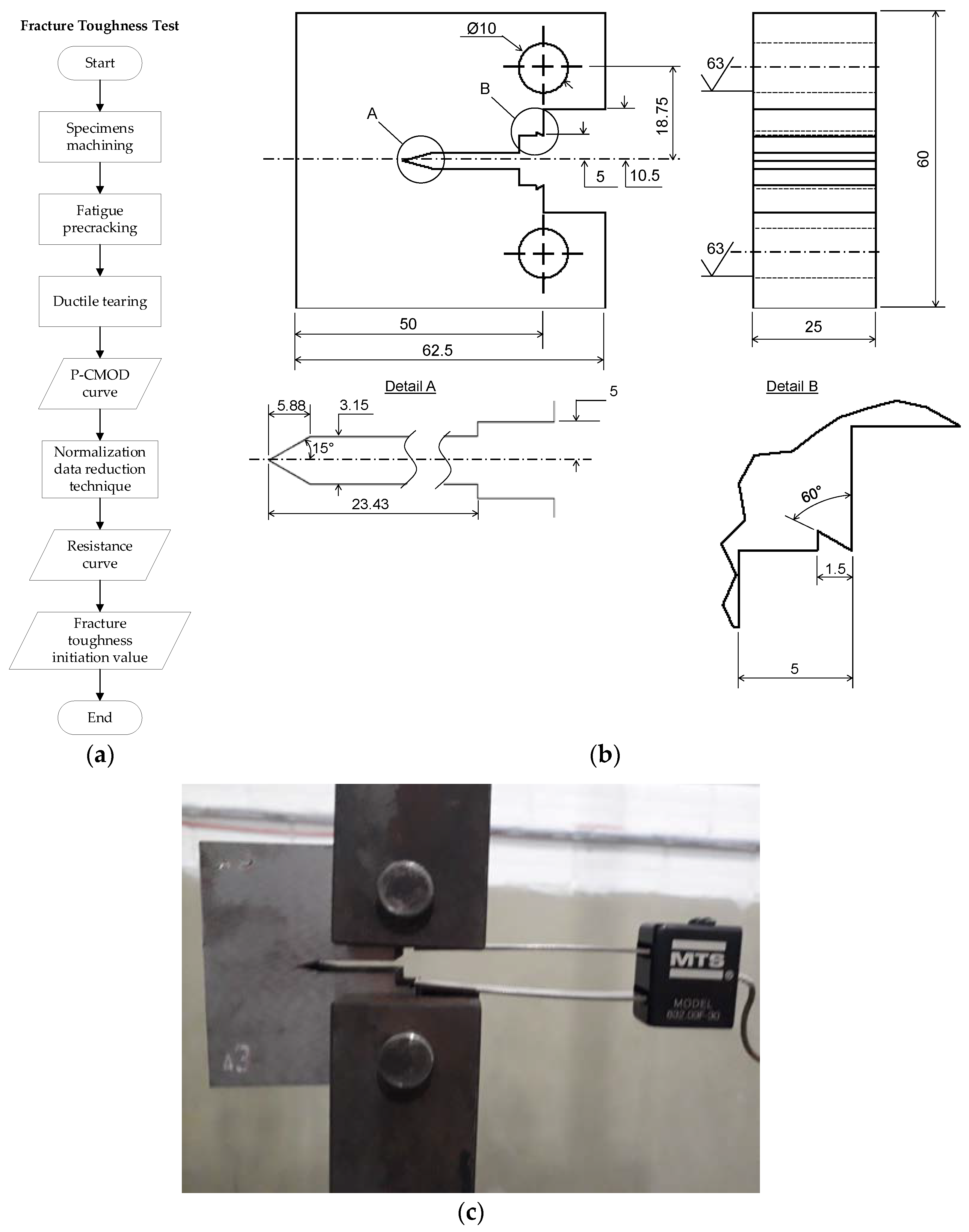
2.4. Fracture Toughness Test and Resistance Curve

The fracture toughness tests were conducted according to the ASTM E1820 [6] and ISO 12135 [7] standards. Figure 3a shows the flowchart with the basic steps involved. The compact tension (CT) specimens were machined according to the dimensions shown in Figure 3b, and step notches were produced using an electric discharge machine. A total of eight specimens had their notches machined parallelly to the rolling direction, while the other eight had their notches machined perpendicularly to the rolling direction. Following, the specimens were submitted to fatigue pre-cracking under cyclic loading with 30 Hz frequency and 0.1 load ratio with an MTS 810 servo-hydraulic universal testing machine. Figure 3c shows one of the specimens assembled and ready to be tested. Later, the specimens were submitted to ductile tearing using a loading ramp of 0.33 kN/s. After tearing, the specimens were taken to 300 °C for 20 min so that the fatigue pre-crack and stable ductile tearing surface were highlighted by heat tinting. Subsequently, specimens were cooled in liquid nitrogen and broken.
The load-crack mouth opening displacement (P vs. CMOD) curve was acquired for every specimen; hence, the resistance curve was derived according to the normalization data reduction technique as per the ASTM E 1820 [6] standard. This technique is used as an alternative method for the construction of resistance curves [23] and has been fully described by Herrera and Landes [24], Landes et al. [25], and Joyce [26]. The method does not require crack growth ( Δ a ) monitoring but the P vs. CMOD curve, the fatigue pre-crack extension ( Δ a f ), and final tearing extension ( Δ a t ) instead [27,28,29]. The crack growth length was inferred iteratively through the agreement of loading, CMOD plastic component ( V p l ) , and crack length, all of them normalized regarding a calibration curve after testing [24,25] with the form:
P N = A + B V p l + C ( V p l ) 2 D + ( V p l W ) ,
where A, B, C, and D are the fitting coefficients determined by the minimum square method and W is a specimen’s dimension. For more details about the steps of this technique, it is advised to consult the ASTM E1820 [6] standard.
Regarding its efficiency, Landes et al. [25], Zhu and Joyce [30], and Landes and Herrera [31] showed very close resistance curves derived with this technique in comparison to the unloading compliance technique for specimens with low and high depth ratios ( a 0 / W ) up to a crack growth length of Δ a = 2 − 6 mm depending on the specimen’s geometry and material.
In the present study, the code written in Matlab® by Linares et al. [32] was used, which is referred to as an open-source alternative for the normalization technique [6,33,34,35]. The code derives J-Integral resistance curves (J-R), which were converted to CTOD resistance curves ( δ -R) according to:
δ = J m X ,
where J is the J-Integral value, X = σ Y S + σ U S 2 for ASTM E1820 [6] and ISO 12135 [7], and m is defined for step-notched CT specimens as:
m = A 0 + A 1 ( σ Y S σ U S ) + A 2 ( σ Y S σ U S ) 2 + A 3 ( σ Y S σ U S ) 3
such that A 0 = 3.62 , A 1 = 4.21 , A 2 = 4.33 , and A 3 = 2.00 .

2.5. Fractography by Scanning Electronic Microscopy

The fracture surfaces for tensile and fracture toughness specimens were analyzed using a Tescan® Vega 3 Scanning Electron Microscope (SEM). The surfaces were carried out following the methodology of González-Velázquez [36] and were cleaned using pressurized air blow and an organic bristle brush, followed by ultrasonic cleaning using an ethylic alcohol solution for 10 min. On the CT fracture surfaces, the stretch zone width ( Δ a s z w ) was measured according to the ISO 12135 [7] standard.

3. Results

3.1. Metallographic Analysis

A metallographic analysis was performed to observe and assess the presence of inclusions, the microstructures, and estimate the grain size.

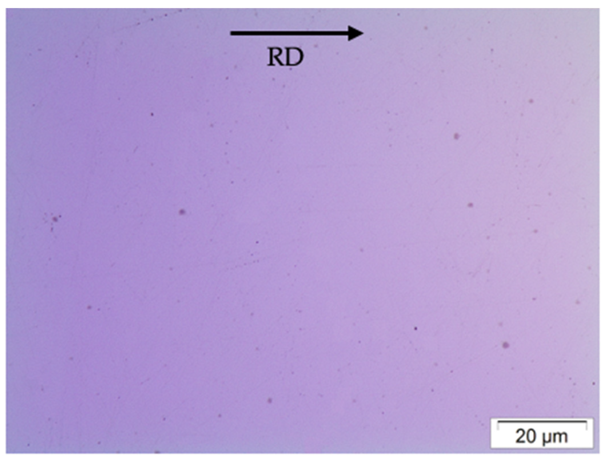
3.1.1. Inclusions Observation

Manganese Sulphide (MnS) inclusions were observed in the steel through optical microscopy as finely dispersed particles with globular morphology, as presented in Figure 4. These inclusions are classified as type I and are formed when oxygen and sulfur solubilities are high and low, respectively [37,38,39,40].

3.1.2. Microstructure Observation

The microstructure revealed by etching is shown in Figure 5. It comprises polygonal ferrite grains (PF) with perlite (P) banding. The estimation analysis of phase volume fraction was obtained using ImageJ® software based on pixel–area relationship and the found results are summarized in Table 1. The mean average percentage of volume fraction obtained when associated with the standard deviation (SD) through the lever rule suggests a hypoeutectoid steel with a carbon content of 0.17 < %C < 0.21, which comprises the estimated carbon content by EDS.

3.1.3. Grain Size Estimation

A total of six metallographic samples were used with 200× amplification for the grain size estimation. On each sample, four parallel and another four perpendicular lines were used to estimate grain size as a function of the rolling direction. Table 2 summarizes the estimates, which allows one to conclude that, despite the rolling process, there was no significant difference in the grain size regarding the plate orientation.

3.2. Tensile Test

3.2.1. Tensile Properties

Figure 6a displays the engineering stress–strain curves obtained from the tensile tests of the specimens with gauge lengths parallel to the rolling direction (SP01, SP02, and SP03) and perpendicular to this direction (SP04, SP05, and SP05). All the tests were performed at a crosshead speed of 0.2 mm/s in the linear region and 1 mm/s for the remainder of the testing. From the twelve specimens (six in each direction), only three of each were validated; that is, necking occurred at the central portion of the gauge length, as shown in Figure 6b. Table 3 presents the obtained mean average mechanical properties as a function of the rolling direction.

3.2.2. Fractography of Tensile Specimens

Figure 7 displays the fracture surface of the SP01 tensile specimen. Figure 7a shows the typical “cup and cone” fracture, which is commonplace in ductile fractures. Highlights are provided to the shear zone (“cone”) and the fibrous zone (“cup”). Figure 7b shows an amplification of the fracture surface, emphasizing the fibrous zone (indicated in yellow and amplified in Figure 7c) and the shear zone (indicated in red and amplified in Figure 7d).
It is possible to observe that the fibrous zone consists of dimples, which suggests the micromechanism of ductile fracture by nucleation, growth, and coalescence of voids. Larger dimples are due to more prominent inclusions and are connected by more minor dimples generated by smaller inclusions. The fracture profile is flat, which is due to the internal necking (or intervoid necking) coalescence mode [41,42,43,44], mainly because of the equiaxial dimples formation, where the highlight in Figure 7c (indicated by yellow dashed circles) presents coalescence larger dimples. It is possible to identify the same coalescence mode on the shear fracture zone, but, in this region, the voids were more enlarged in one direction than the other (indicated by red dashed circles in Figure 7d) due to the shear stress component developed on the onset of necking.
The inclusions’ morphology, distribution, and dimension are perceived by analyzing the fracture surface of the SP02 tensile specimen in Figure 8a,b, an inclusion cluster of varied dimensions, but all with globular morphology. Figure 8c shows an inclusion chosen to be analyzed by EDS, and, in Figure 8d, the obtained spectrum of the elements confirms the chemical composition for MnS inclusions.

3.3. Fracture Toughness Test

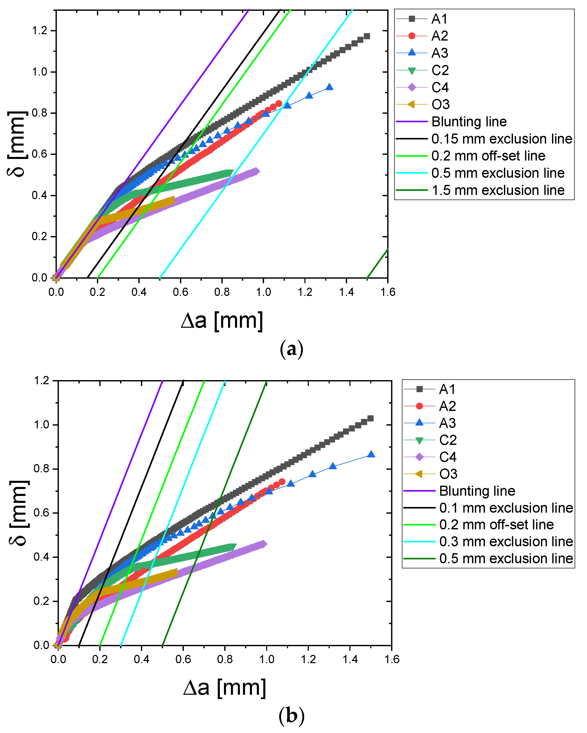
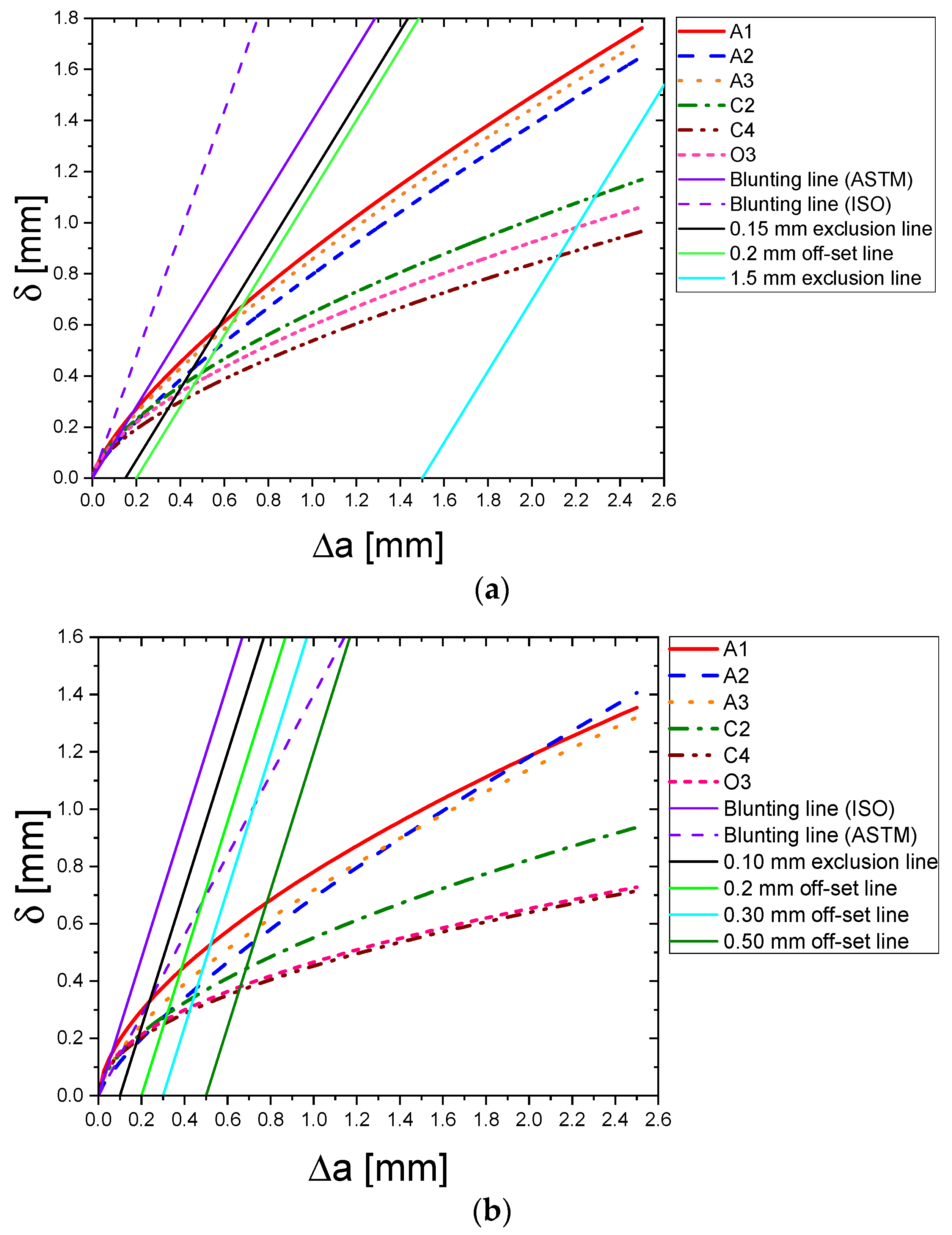
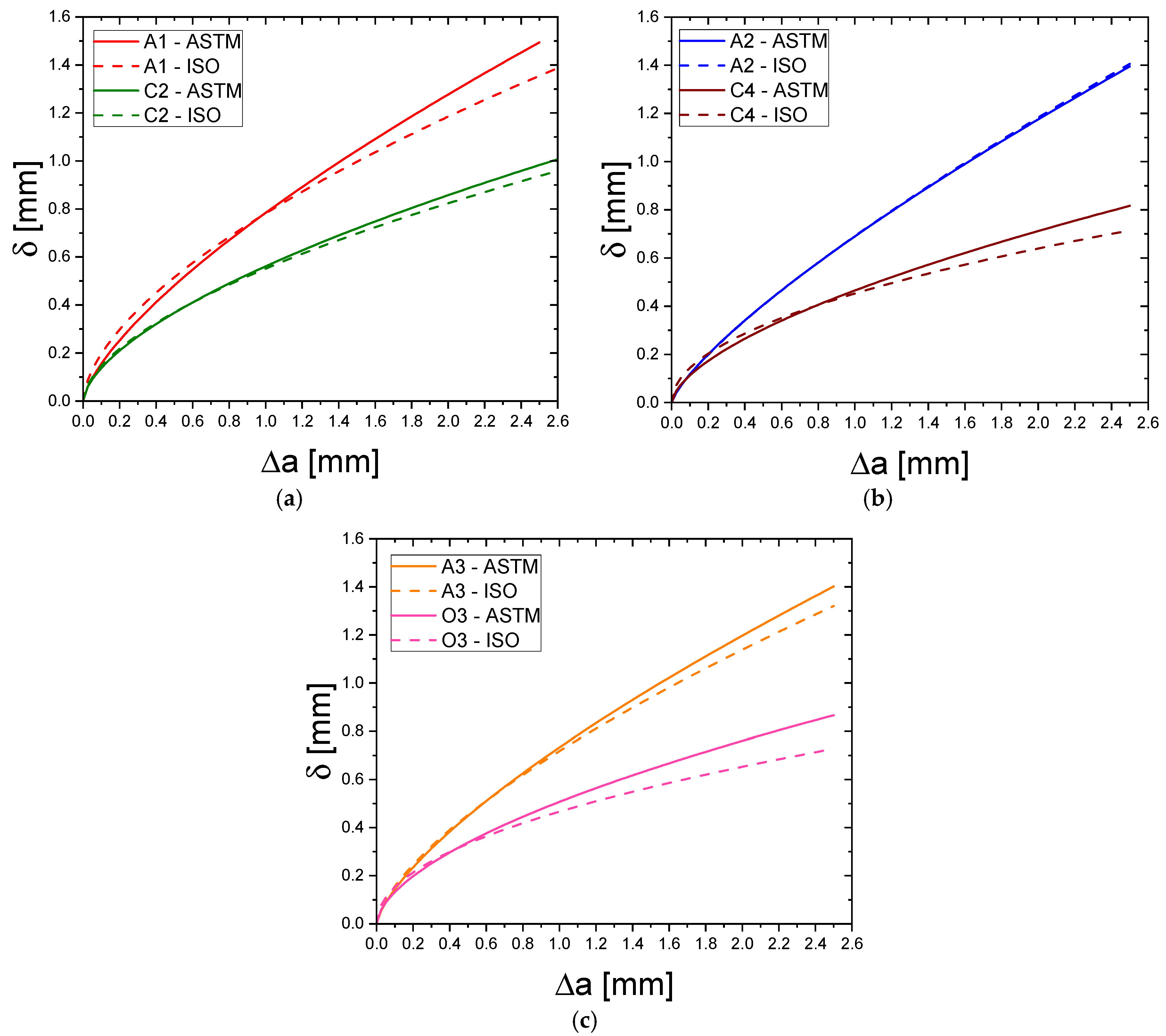
3.3.1. Resistance Curve

From the six specimens tested in each direction, only three were validated by the normalization data reduction technique. The CT specimens were machined such that the A1, A2, and A3 specimens have their notches perpendicular to the rolling direction, while the C2, C4, and O3 specimens possess notches parallel to the rolling direction. All specimens were fatigue pre-cracked, heat tinted, cooled, and broken according to the procedure previously described, and Figure 9a shows an example of a fracture surface obtained. For each specimen, nine surface measurements for fatigue pre-crack and stable ductile tearing were taken and the obtained mean values presented in Table 4; further, other data for each specimen were obtained. Figure 9b shows the load–CMOD curves obtained for each specimen, while Figure 9c displays the obtained resistance curves.
Several authors have reported unstable crack driving forces for a small amount of crack extension when using the normalization data reduction technique [25,28,31,45,46]. Menezes et al. [46] assigned this phenomenon to the high sensibility of crack sizes inferred by Equation (6). On the other hand, Scibetta et al. [47] explained it for small amounts of plastic displacement. However, this phenomenon is not a particular consequence of the normalization data reduction technique and has also been reported for the unload compliance technique [48,49,50], having no physical meaning assigned.
Regardless of the method used, the blunting line is reported as a reference for correcting the data. While some authors [25,31,45,46,47] proposed only the dislocation of the unstable points to the blunting line, others, such as Rosenthal et al. [48], proposed the dislocation of all the resistance curve points proportional to a constant calculated value. In contrast, Seok [49] proposed a dislocation of the curve proportional to the most negative value up to the blunting line, and Underwood et al. [50] calculated the mean value of the distance between the unstable points and the blunting line, dislocating the curve proportionally to that value. The present study considered the dislocation of the unstable points to the blunting line. The corrected curves are shown in Figure 10a,b using the blunting line of the ASTM E1820 [6] and ISO 12135 [7] standards, respectively.
Afterward, a non-linear regression was performed to fit the experimental data to Equation (3) for ASTM E1820 and Equation (4) for ISO 12135. The non-linear regression was performed using MATLAB® with a Levenberg–Marquardt [51] for its robustness regarding the order ascending or descending optimization method and for handling models with multiple free parameters [52]. The coefficients and their analysis of variance (ANOVA) for each resistance curve are presented in Table 5 and Table 6 for ASTM E1820 [6] and ISO 12135 [7], respectively. For every fitted curve in Table 5 and Table 6, the F-value obtained for each regression is much higher than the one on Snedecor’s F-Distribution with a 95% confidence interval, which makes the obtained regression models statistically well-fitted and predictive. The curves are shown in Figure 11a for ASTM E1820 [6] and in Figure 11b for ISO 12135 [7], respectively.
According to both standards, provisional initiation fracture toughness, i.e., the possible crack driving force for which stable crack propagation begins, should be determined by the intersection of the 0.2 mm offset line with the fitted curve. In this manner, the provisional CTOD initiation ( δ Q ) values are provided in Table 7 for ASTM E1820 [6] and ISO 12135 [7], alongside the corresponding tearing modulus ( T = d δ d a ) obtained as the inclination of a line equation from the δ > δ Q points.
Some criteria are required for both standards to be considered valid initiation values (Table 8). Furthermore, Table 9 condenses the criteria calculated for each specimen, where a f is the sum of the notch length to the fatigue pre-crack extension. It can be perceived by comparing Table 7 and Table 9 that the provisional CTOD can be accepted as CTOD initiation according to both standards. Table 10 comprises the CTOD initiation for each specimen according to the standards and a mean and standard deviation as a function of the notch orientation regarding rolling direction.

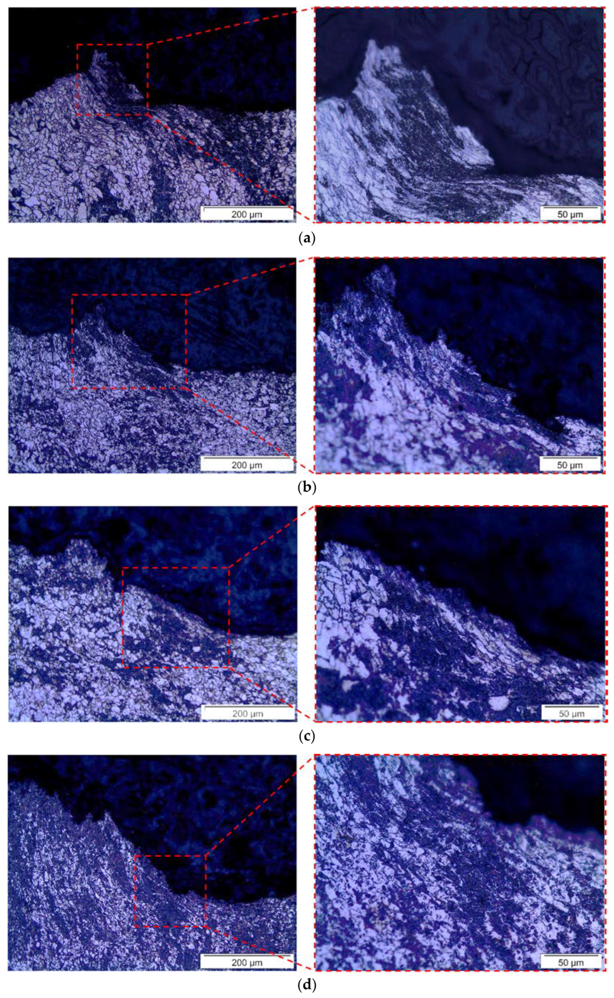
3.3.2. Fractography of C(T) Specimens

Figure 12 shows the fracture surface of the A1 specimen, highlighting the fatigue pre-crack, stretching zone, and stable ductile tearing regions. Typical strain marks are perceivable of the fatigue pre-crack surface, and the formation of dimples by void nucleation, growth, and coalescence features the stable ductile tearing surface.
The stretch zone, delimited between the yellow dashed lines, was measured according to the methodology of ISO 12135 [7], where, on each measured region of the nine points outlined in Figure 9a, five measurements ( Δ a S Z W , i ) were performed such that the local stretch zone width ( Δ a S Z W , L ) was calculated as:
Δ a S Z W , L = 1 k i = 1 k Δ a S Z W , i ,   k 5 ,
and the stretch zone width ( Δ a S Z W ) was calculated as:
Δ a S Z W = 1 9 L = 1 9 Δ a S Z W , L ,
Table 11 summarizes the measurements that were performed.
Using the width of the stretch zone as a crack extension for stable ductile tearing initiation, a stretch zone CTOD initiation ( δ S Z W ) was estimated using the regression models derived for both standards, as illustrated in Figure 11. Table 12 summarizes the results obtained. Taking a mean δ S Z W on each notch orientation, two blunting lines were estimated for the ASTM A516 Gr.70 steel as displayed in Figure 13 alongside the blunting lines of the ASTM E1820 [6] and ISO 12135 standards [7].

3.3.3. Crack Path and Microstructure Interaction

To verify the anisotropy of the fracture toughness outlined by the resistance curves for different notch orientations to the rolling direction, the interaction between the crack path and the microstructure was observed by cutting two of the specimen’s fracture surfaces along the A-A plane, as shown in Figure 9a. These samples were prepared following the steps on the flowchart of Figure 2. Figure 14 reveals the microstructure surrounding the blunted crack tip. Figure 14a,b refers to the A1 and A3 specimens, while Figure 14c,d refers to the C2 and C4 specimens, respectively.

4. Discussion

This article presents an investigation regarding the fracture toughness of the ASTM A516 Gr.70 pressure vessel steel. The presented results indicated an anisotropy when considering the investigated properties. Moreover, the fracture toughness determination according to the ASTM E1820 [6] and ISO 12135 [7] standards yielded different values. Therefore, this research aimed to assess the reasons behind properties’ anisotropy and highlight reasons for the different fracture toughness values obtained for each standard.

4.1. Tensile and Fracture Toughness Anisotropy

The differences observed can be due to the heterogeneity of the material’s microstructure and to the variation of the specimens’ dimensions. Although all specimens followed rigorously the ASTM E8/8M [22] standard regarding their dimensions, different stress–strain curves are still expected because of the dimensional tolerance permitted by the standard, which is explained at its X1 appendix. Specifically, about the differences in terms of the load–CMOD curves of the CT specimens on the same orientation, small differences in dimensions and the microstructure heterogeneity itself are enough to justify such differences. The differences are more pronounced on the fracture toughness specimens because stress triaxiality level ahead of crack front is higher (2.5 or more) than in smooth tensile specimens’ case (1/3), which intensifies the differences observed on the load–CMOD curves. Moreover, small differences in the a 0 W ratio have high impact on the achieved maximum load because of the reduction in the amount of material ligament ahead of the crack front.
It is noticeable from the obtained results that the forming process plays a vital role in the anisotropy of the investigated properties. This is not so perceived on the tensile properties as the mean values in Table 3 are close regarding the gauge length orientation to the rolling direction. However, the fracture surface of tensile specimens exhibited an elliptical geometry (Figure 8a), a clear sign of anisotropy.
The anisotropy is more perceived in the fracture toughness. Figure 9b,c shows that, when the notch is oriented perpendicular to the rolling direction, higher loading values were achieved for the same CMOD value, indicating that more energy was required to initiate the material’s stable ductile tearing, which reflected a higher CTOD initiation and tearing modulus, as indicated in Table 7 and Table 10. This seems to rely on pearlite banding due to the hot-rolling forming process, as Figure 5c highlights. Matrosov and Polyakov [53] indicated an anisotropy index, i.e., a ratio of the highest to the lowest fracture toughness, of 1.25 due only to banding. At the same time, Spitzig [54] and Wilson et al. [55] observed the beneficial effect of microstructure homogenization, specifically the elimination of banding for the upper shelf impact energy, although this impact was not perceived on tensile properties. The justification for this is related to breaking the perlite bands into equiaxial perlite grains or spherical perlite [55]. Although ferrite did not change its grain size statistically due to the forming process, as concluded by the mean grain size measured on both orientations shown in Table 2, when perlite bands are oriented perpendicular to specimens’ notches, they follow the ferrite plastic flow during crack front blunting, as illustrated by Figure 14a,b for the A1 and A3 specimens, respectively. The perlite bands act as a mechanical reinforcement, requiring more energy to initiate stable tearing across perlite and ferrite grains.
On the other hand, when perlite bands are oriented parallel to specimens’ notches, a lower amount of energy is required since tearing seems to initiate between the perlite and ferrite interface, which is evidenced by the presence of a perlite band along the blunted crack fronts on Figure 14c,d for the C2 and C4 specimens, respectively. Because of this, the fracture toughness anisotropy indexes were equal to 1.55 and 1.35, which were calculated from the mean values of Table 12 according to the estimates of ASTM E1820 [6] and ISO 12135 [7] standards’ 0.2 mm offset line. For the estimated stretch zone CTOD initiation, the indexes were equal to 1.25 and 1.22, also calculated by the mean values in Table 12 approximately using ASTM E1820 [6] and ISO 12135 [7] fitted resistance curves, which is consistent with the observations of Matrosov and Polyakov [53].
The morphology of nonmetallic inclusions has been reported by several authors as one of the most responsible for fracture toughness anisotropy in carbon steels, especially when an elongated morphology is to be expected due to forming processes [56,57]. When deformed elongated inclusions are formed, a diminishing fracture toughness is expected at the transverse to the rolling direction [44,45], which was already expected compared to globular-shaped inclusions [54]. The content of inclusions also plays a significant role in fracture anisotropy, as Ghosh et al. [46] observed for two steels with different sulfur content, and, therefore, different sizes and fractions of MnS inclusions. Steels of higher sulfur content tend to produce a higher fraction of MnS inclusions of greater size. As MnS inclusions have relatively great deformation capacity, a significant portion of them of larger sizes will tend to produce type III elongated inclusions after rolling, which were responsible for the lower toughness of the higher-sulfur-content steels observed by Ghosh et al. [58] due to large and elongated dimples formed during ductile tearing. Lower-sulfur-content steels have produced more diminutive and more equiaxial globular type I inclusions, which occasioned more dimple formation, responsible for higher fracture toughness obtained for these steels. Therefore, although inclusions of any type may be detrimental to fracture toughness, type III elongated inclusions are more detrimental than type I globular inclusions [54,57]. Type I MnS inclusions were observed (Figure 4 and Figure 8a,b) and were the main reason for the high fracture toughness of the studied ASTM A516 Gr.70 steel. This was due to the low content of sulphur verified by EDS, shown in Figure 8d, which was also the main reason for the low dimensions of these inclusions (Figure 8b). As the MnS type I inclusions were randomly distributed, it did not seem to contribute to fracture toughness anisotropy on the studied material.
Mohan et al. [56] suggest three main contributors to fracture toughness anisotropy: morphology, content, and distribution of inclusions; banding of microstructure; and crystallographic texture. The last one is absent from previous discussions. Crystallographic texture, or preferred orientation, refers to planes and directions that are oriented by, for example, the forming process of the metalworking direction. Therefore, certain slip systems are conditioned to the rolling direction, which has an important influence on fracture toughness anisotropy [56,59]. Ju, Lee, and Jang [60] demonstrated the effect of crystallographic texture on the fracture toughness of the API 5L X65 pipeline steel using texture analysis through pole figure measurement of the volume fraction of crystallographic planes as a function of the angle to the rolling direction of the plates. Their results showed that all the planes had uniform distribution, but the {110} plane showed more density in the transverse to the rolling direction [61,62]. The {110} plane is one of the most densely packed planes of body-centered cubic (BCC) ferrite crystals, being, therefore, responsible for the plastic deformation that precedes ductile tearing at the upper shelf regime, and this was the reason the authors provided to explain the higher fracture toughness observed at the transverse direction in comparison to the rolling direction. Inoue and Kimura [56,59] used electron backscattered diffraction (EBSD) to infer the slip systems of each direction of a hot-rolled ultra-fine-grain steel and found that, at the rolling direction, there was a density of {100}<110> slip systems, which contain the {100} plane, which is known to be an easy cleavage plane [63], and, therefore, responsible for the lower fracture toughness at this direction. The same conclusions were stated by Das et al. [64] for a 13%Cr hot-rolled oxide-dispersion-strengthened steel. In the current study, the crystallographic texture was not explored, but its influence on the fracture toughness of the ASTM A516 Gr.70 steel is a possibility.
The relation between the anisotropy and the orientation of the specimens is the following: when the crack plane is perpendicular to the rolling direction, more energy is required to tear the material volume ahead of the crack front, which was the case of the A1, A2, and A3 CT specimens, which exhibited higher tearing modulus and CTOD initiation values, and the case of the SP04, SP05, and SP06 tensile specimens, which visually exhibited higher areas under the stress–strain curves, i.e., higher toughness. On the other hand, lower toughness was observed on the C2, C4, and O3 CT specimens, which exhibited lower tearing modulus and CTOD initiation values, and SP01, SP02, and SP03 tensile specimens, which visually exhibited lower areas under the stress–strain curves. One question may arise concerning the repeatability of this microstructural-to-macromechanical effect on fracture toughness: would a similar trend be observed on a steel plate of the ASMT A516 Gr.70 steel from another manufacturer? According to its standard, the ASTM A516 Gr.70 steel plates are manufactured by hot rolling [18]. Plates with thickness up to 40 mm are normally supplied in the as-rolled condition, while plates over 40 mm in thickness shall be normalized. Therefore, the same effect would be perceived when comparing ASTM A516 Gr.70 steel plates from different manufacturers, but differences could arise when comparing plates with different thicknesses, as previously discussed. Since normalization is a heat treatment on which cooling rates assume higher values than annealing, the austenitic transformation occurs out of thermodynamic equilibrium, placing an adverse condition for atomic diffusion of carbon atoms [65]. Then, the pearlite formation is only assured by the decrease in the mean interlamellar spacing, which results in higher perlite volume fraction and higher ferrite content in the perlite, therefore, resulting in higher mechanical strength [65,66]. Specifically, concerning fracture toughness, this increase is justified by higher ferrite content in the perlite, making it more tough, and also by the decrease in the mean interlamellar spacing itself [65], which would result in more pearlite bands acting as mechanical reinforcements ahead of the crack front.

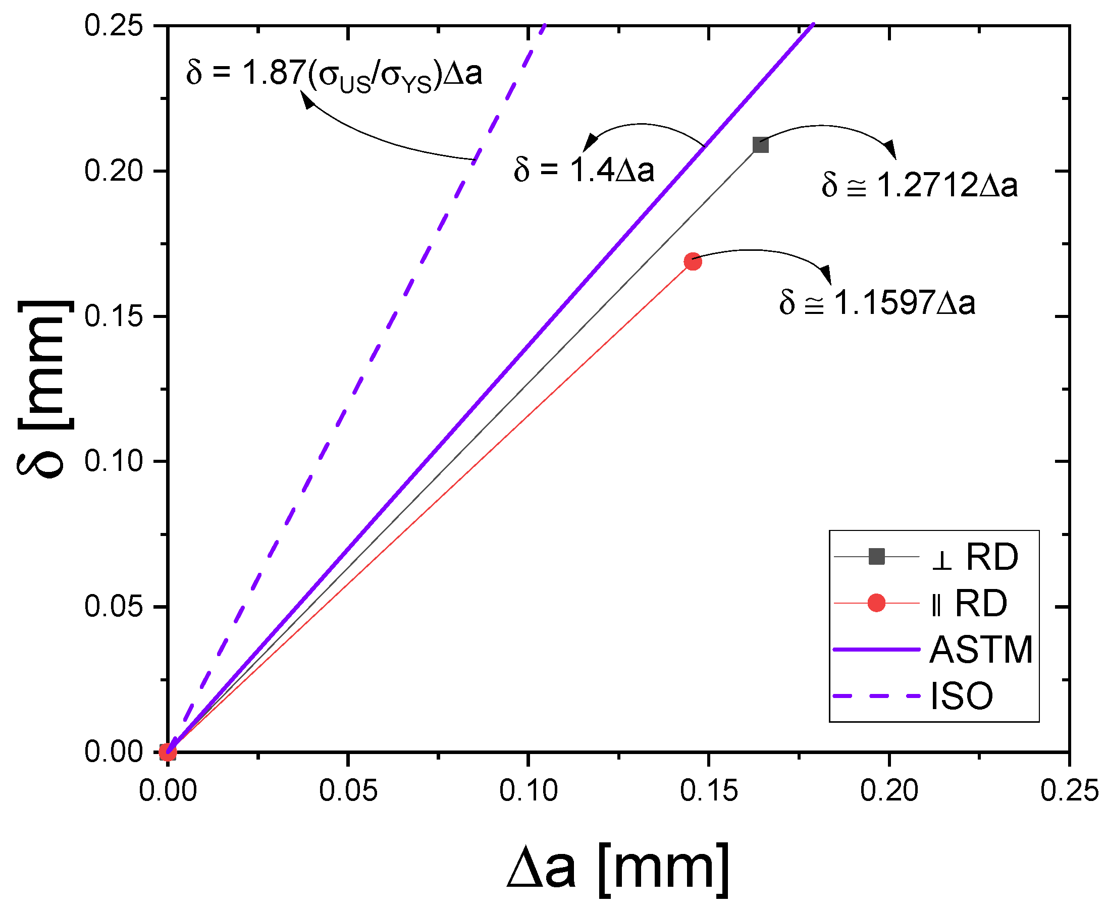
4.2. Differences between ASTM and ISO Estimated Fracture Toughness

ASTM E1820 [6] and ISO 12135 [7] have yielded different results for CTOD initiation regardless of notch orientation to the rolling direction and despite both standards using the same approach based on the interception of a 0.2 mm offset line with the same slope as the blunting line to the fitted resistance curve. The slope of the blunting line is precisely the justification for the different estimated CTOD initiation values. Since the ISO 12135 [7] blunting line (Equation (2)) exhibits a higher slope for the present material than the ASTM E1820 [6] blunting line (Equation (1)), as observed in Figure 13, the CTOD initiation values estimated by the former are lower than the ones estimated by the latter, which has been an issue pointed out by some authors [8,9,11]. The estimated blunting lines for the ASTM A516 Gr.70 steel are shown in Figure 13 and were based on the CTOD initiation values estimated by the stretch zone width. This reinforces the necessity of a blunting line estimation based on the materials’ deformation behavior since the slope also depends on the material’s work hardening coefficient [17,67].
Other minor contributions to the different reported fracture toughness estimations are the distance between the exclusion lines and the fitting equations. The former relates to the number of δ Δ a points to be considered for the resistance curve validation. According to ASTM E1820 [6], at least one point should lie between the 0.15 mm and the 0.5 mm exclusion lines, and at least another point should lie between the 0.5 mm and 1.5 mm exclusion lines. From Figure 11a, it is possible to observe that, considering this criterion, the A2, C2, and O3 specimens would not have their resistance curve validated. On the other hand, according to ISO 12135 [7], at least one point must lie between the 0.1 mm and 0.3 mm exclusion lines and at least two points must lie between the 0.1 mm and 0.5 mm exclusion lines, making all specimens’ resistance curves valid, as shown in Figure 11b, and, therefore, it can be stated that the ISO 12135 [7] exclusion lines allow more points to be included in the resistance curves validation procedure.
The fitted resistance curves of Figure 11 are shown in Figure 15 for each standard fitting equation to allow their comparison. It can be noticed that both ASTM E1820 [6] and ISO 12135 [7] curves are very close for Δ a < 1   mm and, in the current study, have almost no influence on the predicted initiation fracture toughness values. This is also corroborated by the close mean values estimated by the width of the stretch zone indicated in Table 12.
Comparing the estimated CTOD initiation values by the standards with the estimated values using the stretch zone width (Table 12), it can be realized that the standard estimated values are as high as approximately 2.56 times the values estimated by the width of the stretch zone depending on the standard and orientation. Since the stretch zone width is defined as physical evidence of the ductile tearing initiation [9,17,68,69,70], this implies some concerns about the methodology adopted by both ASTM E1820 [6] and ISO 12135 [7] using the 0.2 mm offset line and emphasizes the necessity of estimating the fracture initiation toughness based on the stretch zone measurement.

5. Conclusions

Fracture toughness tests were carried out, and the ductile fracture behavior of the ASTM A516 Gr.70 pressure vessel steel was studied employing the resistance curve with toughness fracture initiation estimated according to the ASTM E1820 and ISO 12135 standards. The toughness fracture anisotropy observed on this steel seems to be mainly originated from the banding of perlite that acts as mechanical reinforcement when the specimens’ notches are perpendicular to the rolling direction of the plate, demanding more tearing energy across the perlite and ferrite grains. Therefore, higher fracture toughness was observed. On the other hand, when specimens’ notches are parallel to the rolling direction, a lower amount of tearing energy is required since tearing seems to initiate between the perlite and ferrite interface.
The toughness fracture initiation estimated by the ASTM E1820 and ISO 12135 standards led to different results, even considering the same orientation, and the values obtained with ISO 12135 were lower than the ones obtained by ASTM E1820. The difference is mainly attributed to the blunting line slope used on each standard. Other minor influences cited by other authors, such as the distance between exclusion lines and fitting equations, did not significantly affect the estimated values. Regardless of the adopted standard, a concerning overestimation of the fracture initiation values was observed when compared to the initiation value estimated by the stretch zone measurement, which suggests the zone’s dimension as a more real fracture toughness estimator.

Author Contributions

Conceptualization, G.d.C.C., A.A.S. and M.A.d.S.; methodology, G.d.C.C.; formal analysis, G.d.C.C., J.J.M.M. and J.M.R.S.T.; investigation, G.d.C.C. and M.A.d.S.; resources, A.A.S. and M.A.d.S.; writing—original draft preparation, G.d.C.C.; writing—review and editing, G.d.C.C., A.A.S., M.A.d.S., J.J.M.M. and J.M.R.S.T.; visualization, G.d.C.C.; supervision, A.A.S. and M.A.d.S.; project administration, A.A.S.; funding acquisition, A.A.S. All authors have read and agreed to the published version of the manuscript.

Funding

This research was funded by the Brazilian National Council for Scientific and Technological Development (CNPq): grant number 408131/2018-7, and the Coordination for the Improvement of Higher Education Personnel (CAPES).

Data Availability Statement

The data presented in this study are available on request from the corresponding author. The data are not publicly available due to privacy.

Conflicts of Interest

The authors declare no conflict of interest.

References

  1. Ashby, M.F. Materials selection in conceptual design. Mater. Sci. Technol. 1989, 5, 517–525. [Google Scholar] [CrossRef]
  2. Underwood, J.H.; Troiano, E. Critical Fracture Processes in Army Cannons: A Review. J. Press. Vessel. Technol. 2003, 125, 287–292. [Google Scholar] [CrossRef]
  3. Underwood, J.H.; Farrara, R.A.; Audino, M.J. Yield-Before-Break fracture mechanics analysis of high-strength steel pressure vessels. J. Press. Vessel. Technol. 1995, 117, 79–84. [Google Scholar] [CrossRef]
  4. Bourga, R.; Moore, P.; Janin, Y.J.; Wang, B.; Sharples, J. Leak-before-break: Global perspectives and procedures. Int. J. Press. Vessel. Pip. 2015, 129–130, 43–49. [Google Scholar] [CrossRef]
  5. Ukadgaonker, V.G.; Babu, R.S. Review of work related to ‘leak-before-break’ assessment. Int. J. Press. Vessel. Pip. 1996, 69, 135–148. [Google Scholar] [CrossRef]
  6. ASTM E1820-22e1; Standard Test Method for Measurement of Fracture Toughness. ASTM International: West Conshohocken, PA, USA, 2022. [CrossRef]
  7. ISO 12135:2016; Metallic Materials—Unified Method of Test for the Determination of Quasistatic Fracture Toughness. ISO: Geneva, Switzerland, 2021.
  8. Landes, J.D. Evaluation of the ISO J initiation procedure using the EURO fracture toughness data set. Int. J. Fract. 2007, 145, 285–297. [Google Scholar] [CrossRef]
  9. Arora, K.S.; Viehrig, H.W. Evaluation of the ASTM and ISO J initiation procedures by applying the unloading compliance technique to reactor pressure vessel steels. J. Test. Eval. 2011, 39, 975–984. [Google Scholar] [CrossRef]
  10. Khandelwal, H.; Singh, R.; Chakravartty, J. Fracture-toughness evaluation of solution heat-treated Zr-2.5 Nb alloys as per ASTM and ISO standards. J. Test. Eval. 2016, 44, 1542–1557. [Google Scholar] [CrossRef]
  11. Li, X.; Ding, Z.; Liu, C.; Bao, S.; Gao, Z. Evaluation and comparison of fracture toughness for metallic materials in different conditions by ASTM and ISO standards. Int. J. Press. Vessel. Pip. 2020, 187, 104189. [Google Scholar] [CrossRef]
  12. Landes, J.D. The blunting line in elastic-plastic fracture. Fatigue Fract. Eng. Mater. Struct. 1995, 18, 1289–1297. [Google Scholar] [CrossRef]
  13. Gao, H.; Wang, W.; Wang, Y.; Zhang, B.; Li, C.Q. A modified normalization method for determining fracture toughness of steel. Fatigue Fract. Eng. Mater. Struct. 2021, 44, 16. [Google Scholar] [CrossRef]
  14. Malito, L.G.; Sov, J.V.; Gludovatz, B.; Ritchie, R.O.; Pruitt, L.A. Fracture toughness of ultra-high molecular weight polyethylene: A basis for defining the crack-initiation toughness in polymers. J. Mech. Phys. Solids 2019, 122, 15. [Google Scholar] [CrossRef]
  15. Mokhtarishirazabad, M.; Mostafavi, M. Some observations on failure of austenitic stainless steel: Effects of in- and out of plane constraint. Procedia Struct. Integr. 2019, 18, 15. [Google Scholar] [CrossRef]
  16. Rice, J.R.; Sorensen, E.P. Continuing crack-tip deformation and fracture for plane-strain crack growth in elastic-plastic solids. J. Mech. Phys. Solids 1978, 26, 163–186. [Google Scholar] [CrossRef]
  17. Bansal, S.; Nath, S.K.; Ghosh, P.K.; Ray, S. Stretched zone width and blunting line equation for determination of initiation fracture toughness in low carbon highly ductile steels. Int. J. Fract. 2009, 159, 43–50. [Google Scholar] [CrossRef]
  18. ASTM A516/A516M-17; Standard Specification for Pressure Vessel Plates, Carbon Steel, for Moderate- and Lower-Temperature Service. ASTM International: West Conshohocken, PA, USA, 2017. [CrossRef]
  19. ASTM E3-11; Standard Guide for Preparation of Metallographic Specimens. ASTM International: West Conshohocken, PA, USA, 2017. [CrossRef]
  20. ASTM E407-07; Standard Practice for Microetching Metals and Alloys. ASTM International: West Conshohocken, PA, USA, 2015. [CrossRef]
  21. ASTM E112-13; Standard Test Methods for Determining Average Grain Size. ASTM International: West Conshohocken, PA, USA, 2021. [CrossRef]
  22. ASTM E8/E8M-22; Standard Test Methods for Tension Testing of Metallic Materials. ASTM International: West Conshohocken, PA, USA, 2022. [CrossRef]
  23. Zhu, X.-K.; Joyce, J.A. Review of fracture toughness (G, K, J, CTOD, CTOA) testing and standardization. Eng. Fract. Mech. 2012, 85, 1–46. [Google Scholar] [CrossRef]
  24. Herrera, R.; Landes, J.D.; Direct, J.-R. Curve Analysis: A Guide to the Methodology. In Fracture Mechanics: Twenty-First Symposyum—ASTM STP 1074; Gudas, J.P., Joyce, J.A., Hackett, E.M., Eds.; ASTM International: Conshohocken, PA, USA, 1990; pp. 24–43. [Google Scholar] [CrossRef]
  25. Landes, J.; Zhou, Z.; Lee, K.; Herrera, R. Normalization method for developing JR curves with the LMN function. J. Test. Eval. 1991, 19, 305–311. [Google Scholar] [CrossRef]
  26. Joyce, J.A. Analysis of a high rate round robin based on proposed annexes to ASTM E 1820. J. Test. Eval. 2001, 29, 329–351. [Google Scholar] [CrossRef]
  27. Fernández-Pisón, P.; Rodríguez-Martínez, J.A.; García-Tabarés, E.; Avilés-Santillana, I.; Sgobba, S. Flow and fracture of austenitic stainless steels at cryogenic temperatures. Eng. Fract. Mech. 2021, 258, 28. [Google Scholar] [CrossRef]
  28. Rybakina, O.G.; Strogonova, O.A. A Method of the JR-curve Determination Using Linear Normalization. In Advances in Solid and Fracture Mechanics: A Liber Amicorum to Celebrate the Birthday of Nikita Morozov, 1st ed.; Altenbach, H., Bauer, S.M., Belyaev, A.K., Indeitsev, D.A., Matveenko, V.P., Petrov, Y.V., Eds.; Springer International Publishing: Cham, Switzerland, 2022; pp. 211–220. [Google Scholar] [CrossRef]
  29. Gao, H.; Li, C.-Q.; Wang, W.; Wang, Y.; Zhang, B. Factors affecting the agreement between unloading compliance method and normalization method. Eng. Fract. Mech. 2020, 235, 14. [Google Scholar] [CrossRef]
  30. Zhu, X.-K.; Joyce, J.A. J–Resistance curve testing of HY80 steel using SE(B) specimens and normalization method. Eng. Fract. Mech. 2007, 74, 2263–2281. [Google Scholar] [CrossRef]
  31. Landes, J.D.; Herrera, R. A new look at J-R curve analysis. Int. J. Fract. 1988, 36, R9–R14. [Google Scholar] [CrossRef]
  32. Linares, A.E.; Clowers, L.; Chen, X.; Sokolov, M.; Nanstad, R. Using automated J-R Curve analysis software to simplify testing and save time. Adv. Mater. Process. 2019, 177, 4. [Google Scholar]
  33. Lucon, E.; Benzing, J.; Hrabe, N. Effect of Precrack Configuration and Lack-of-Fusion on the Elastic-Plastic Fracture Toughness of Additively Manufactured Ti-6Al-4V parts. Mater Perform Charact 2020, 9, 25. [Google Scholar] [CrossRef] [PubMed]
  34. Tan, L.; Chen, X.F. Intermediate-Term Thermal Aging Effect Evaluation for Grade 92 and 316L at the LWR Relevant Temperature; Oak Ridge National Lab. (ORNL): Oak Ridge, TN, USA, 2020; p. 27. [Google Scholar]
  35. Tan, L.; Chen, X. Long-Term Thermal Aging Effect Evaluation for Grade 92 and 316L at The LWR Relevant Temperature; Oak Ridge National Lab. (ORNL): Oak Ridge, TN, USA, 2021; p. 32. [Google Scholar]
  36. González-Velázquez, J.L. Fractography and Failure Analysis, 1st ed.; Springer: Cham, Switzerland, 2018; p. 165. [Google Scholar] [CrossRef]
  37. Liu, D.; Xue, Z.; Song, S. Effect of Manganese on the Formation Mechanism of Nonmetallic Inclusions in Fe–xMn–7Al–0.7 C Lightweight Steel. Steel Res. Int. 2023, 94, 10. [Google Scholar] [CrossRef]
  38. Xu, X.-Y.; Zeng, Z.-Q.; Tian, Q.-R.; Cao, C.-W.; Shen, P.; Fu, J.-X. Application of fractal theory to study morphology of manganese sulfide inclusion in resulfurized free-cutting steels. J. Iron Steel Res. Int. 2023, 30, 13. [Google Scholar] [CrossRef]
  39. Liu, N.; Tian, Q.; Wang, Z.; Xu, X.; Fu, J. Modification of MnS inclusion with trace tellurium to improve the machinability of medium-carbon low-sulfur steel. Ironmak. Steelmak. 2023, 1–9. [Google Scholar] [CrossRef]
  40. Tian, Q.; Liu, B.; Shen, W.; Hu, T.; Fu, J.; Xu, X. Nucleation, Growth, Sintering, and Densification of Sulfide in 1215MS Free-Cutting Steel Billet. Steel Res. Int. 2023, 1–11. [Google Scholar] [CrossRef]
  41. Chen, Z.; Butcher, C. Micromechanics Modelling of Ductile Fracture, 1st ed.; Springer: Dordrecht, The Netherlands, 2013; p. 307. [Google Scholar] [CrossRef]
  42. Pineau, A.; Pardoen, T. Failure of Metals. In Comprehensive Structural Integrity; Milne, I., Ritchie, R.O., Karihaloo, B., Eds.; Pergamon: Oxford, UK, 2007; Volume 2, pp. 684–797. [Google Scholar] [CrossRef]
  43. Argon, A.S.; Im, J.; Safoglu, R. Cavity formation from inclusions in ductile fracture. Metall. Trans. A 1975, 6, 825. [Google Scholar] [CrossRef]
  44. Pineau, A.; Benzerga, A.A.; Pardoen, T. Failure of metals I: Brittle and ductile fracture. Acta Mater. 2016, 107, 424–483. [Google Scholar] [CrossRef]
  45. Džugan, J.; Viehrig, H.W. Application of the normalization method for the determination of J–R curves. Mater. Sci. Eng. A 2004, 387–389, 307–311. [Google Scholar] [CrossRef]
  46. de Menezes, J.T.O.; Ipiña, J.E.P.; Castrodeza, E.M. Normalization method for J-R curve determination using SENT specimens. Eng. Fract. Mech. 2018, 199, 658–671. [Google Scholar] [CrossRef]
  47. Scibetta, M.; Lucon, E.; Schuurmans, J.; van Walle, E. Numerical simulations to support the normalization data reduction technique. Eng. Fract. Mech. 2006, 73, 524–534. [Google Scholar] [CrossRef]
  48. Rosenthal, Y.; Tobler, R.; Purtscher, P. JIC Data Analysis Methods with a “Negative Crack Growth” Correction Procedure. J. Test. Eval. 1990, 18, 301–304. [Google Scholar] [CrossRef]
  49. Seok, C.-S. Correction methods of an apparent negative crack growth phenomenon. Int. J. Fract. 2000, 102, 259–269. [Google Scholar] [CrossRef]
  50. Underwood, J.; Troiano, E.; Abbott, R. Simpler JIC Test and Data Analysis Procedures for High-Strength Steels. In Fracture Mechanics: Twenty-Fourth Volume; Landes, J.D., McCabe, D.E., Boulet, J.A.M., Eds.; ASTM International: Philadelphia, PA, USA, 1994; Volume 24, pp. 410–421. [Google Scholar] [CrossRef]
  51. Marquardt, D.W. An algorithm for least-squares estimation of nonlinear parameters. J. Soc. Ind. Appl. Math. 1963, 11, 431–441. [Google Scholar] [CrossRef]
  52. Nelles, O. Nonlinear System Identification: From Classical Approaches to Neural Networks, Fuzzy Models, and Gaussian Processes, 1st ed.; Springer: Cham, Switzerland, 2020; p. 1225. [Google Scholar] [CrossRef]
  53. Matrosov, Y.I.; Polyakov, I.E. Increasing the toughness and ductility and decreasing the property anisotropy of low-allow steels. Stal 1976, 2, 162–167. [Google Scholar]
  54. Spitzig, W.A. Effect of sulfide inclusion morphology and pearlite banding on anisotropy of mechanical properties in normalized C-Mn steels. Metall. Trans. A 1983, 14, 271–283. [Google Scholar] [CrossRef]
  55. Wilson, P.C.; Murty, Y.V.; Kattamis, T.Z.; Mehrabian, R. Effect of homogenization on sulphide morphology and mechanical properties of rolled AISI 4340 steel. Met. Technol. 1975, 2, 241–244. [Google Scholar] [CrossRef]
  56. Mohan, R.; Marschal, C.; Krishnaswamy, P.; Brus, F.; Ghadiali, N.; Wilkowski, G.M. Effects of Toughness Anisotropy and Combined Tension, Torsion, and Bending Loads on Fracture Behavior of Ferritic Nuclear Pipe; NUREG/CR-6299; U.S. Nuclear Regulatory Commission: Columbus, OH, USA, 1995; p. 117.
  57. Baker, T.J.; Gave, K.B.; Charles, J.A. Inclusion deformation and toughness anisotropy in hot-rolled steels. Met. Technol. 1976, 3, 183–193. [Google Scholar] [CrossRef]
  58. Ghosh, A.; Modak, P.; Dutta, R.; Chakrabarti, D. Effect of MnS inclusion and crystallographic texture on anisotropy in Charpy impact toughness of low carbon ferritic steel. Mater. Sci. Eng. A 2016, 654, 298–308. [Google Scholar] [CrossRef]
  59. Inoue, T.; Kimura, Y. Effect of initial notch orientation on fracture toughness in fail-safe steel. J. Mater. Sci. 2013, 48, 4766–4772. [Google Scholar] [CrossRef]
  60. Ju, J.-B.; Lee, J.-S.; Jang, J.-I. Fracture toughness anisotropy in a API steel line-pipe. Mater. Lett. 2007, 61, 5178–5180. [Google Scholar] [CrossRef]
  61. Wang, Y.; Ma, H.; Zhang, Y. Effect of the notch depth on fracture behavior of TC4 titanium alloy sheets. Eng. Fract. Mech. 2023, 277, 18. [Google Scholar] [CrossRef]
  62. Ji, S.; Ren, Y.; Zhang, L. Inclusions in Calcium-Treated and Resulfurized Al-Killed Steels. Steel Res. Int. 2023, 18, 2200838. [Google Scholar] [CrossRef]
  63. Krasovskii, A.Y.; Vainshtok, V.A. Crystallography of cleavage in BCC metals. Strength Mater. 1977, 9, 1091–1099. [Google Scholar] [CrossRef]
  64. Das, A.; Viehrig, H.W.; Bergner, F.; Heintze, C.; Altstadt, E.; Hoffmann, J. Effect of microstructural anisotropy on fracture toughness of hot rolled 13Cr ODS steel—The role of primary and secondary cracking. J. Nucl. Mater. 2017, 491, 83–93. [Google Scholar] [CrossRef]
  65. González, J.I.V.; Fernández-González, D.; González, L.F.V. Physical Metallurgy and Heat Treatment of Steel; Springer: Cham, Switzerland, 2022; p. 332. [Google Scholar] [CrossRef]
  66. Ray, B.C.; Prusty, R.K.; Nayak, D. Phase Transformations and Heat Treatments of Steels, 1st ed.; CRC Press: Boca Raton, FL, USA, 2020; p. 222. [Google Scholar] [CrossRef]
  67. Mills, W.J. On the relationship between stretch zone formation and the J Integral for high strain-hardening materials. J. Test. Eval. 1981, 9, 56–62. [Google Scholar] [CrossRef]
  68. Weidner, A.; Mottitschka, T.; Biermann, H.; Henkel, S. Determination of stretch zone width and height by powerful 3D SEM imaging technology. Eng. Fract. Mech. 2013, 108, 294–304. [Google Scholar] [CrossRef]
  69. Park, S.; Kayani, S.H.; Park, E.H.; Kim, J.G.; Kim, S.; Sung, H.; Seol, J.B. Microstructural Effects on J-Integral Fracture Toughness of Welded High-Mn Steels at 298 and 77 K. Steel Res. Int. 2023, 94, 8. [Google Scholar] [CrossRef]
  70. Sakurai, T.; Umezawa, O. Fracture toughness and martensitic transformation in type 316LN austenitic stainless steel extra-thick plates at 4.2 K. Mater. Sci. Eng. A 2023, 862, 12. [Google Scholar] [CrossRef]
Figure 1. EDS spectrum for the chemical composition of the studied ASTM A516 Gr.70 steel.
Metals 13 00867 g001
Figure 2. (a) Drawing of the tensile specimens (dimensions in mm). (b) Used MTS 810 servo-hydraulic universal testing machine. (c) One tensile specimen assembled on the testing machine.
Metals 13 00867 g002
Figure 3. (a) Flowchart of the adopted fracture toughness test. (b) Drawing of the CT fracture toughness specimens (dimensions in mm). (c) One CT specimen assembled for testing.
Metals 13 00867 g003
Figure 4. Type I MnS inclusions found on the studied ASTM A516 Gr.70 steel (amplification: 1000×).
Metals 13 00867 g004
Figure 5. Microstructure of the studied ASTM A516 Gr.70 steel (amplification: (a) 50×, (b) 100×, (c) 200×, and (d) 500×).
Metals 13 00867 g005
Figure 6. (a) Engineering stress–strain curve for the tensile specimens. (b) One tensile specimen with necking and rupture at the central portion of the gauge length.
Metals 13 00867 g006
Figure 7. Fracture surface of the SP01 tensile specimen. (a) Fibrous (indicated in yellow) and shear (indicated in red) zone (amplification of 69×). (b) “Cup and cone” fracture (amplification of 200×). (c) Dimpled surface of the fibrous zone (amplification of 1000×) and (d) shear zone (amplification: 1000×).
Metals 13 00867 g007
Figure 8. Fracture surface of the SP02 tensile specimen. (a) Cluster of inclusions and (b) varied dimensions but globular morphology. (c) Inclusion chosen for EDS and (d) spectrum confirming the chemical composition of MnS inclusion.
Metals 13 00867 g008
Figure 9. (a) Example of mean nine points of crack length measurement on the C2 specimen. Load-CMOD curves for the CT specimens with notches (b) perpendicular and (c) parallel to the rolling direction.
Metals 13 00867 g009
Figure 10. Resistance curve with blunting line correction for (a) ASTM E1820 [6] and (b) ISO 12135 standards [7].
Metals 13 00867 g010
Figure 11. Fitted resistance curve for (a) ASTM E1820 [6] and (b) ISO 12135 standards [7].
Metals 13 00867 g011
Figure 12. Fracture surface of the A1 CT specimen (amplification of 10×), fatigue pre-crack (amplification of 1000×), stretch zone (amplification of 230×), and stable ductile tearing (amplification of 1000×).
Metals 13 00867 g012
Figure 13. Comparison between blunting lines according to the ASTM E1820 [6] and ISO 12135 [7] standards and the estimated lines for the ASTM A516 Gr.70 steel.
Metals 13 00867 g013
Figure 14. Microstructure surrounding the blunted crack front (amplification of 200×) with the corresponding highlight (amplification of 500×) for the (a) A1, (b) A3, (c) C2, and (d) C4 specimens.
Metals 13 00867 g014
Figure 15. Comparison between the ASTM E1820 [6] and ISO 12135 [7] fitted resistance curves for the (a) A1 and C2, (b) A2 and C4, and (c) A3 and O3 specimens.
Metals 13 00867 g015
Table 1. Volumetric fraction percentage obtained for each studied sample.
SamplePerliteFerrite
123.64%76.37%
221.70%78.30%
319.47%80.53%
426.05%73.95%
Mean22.71%77.29%
SD2.80%
Table 2. Estimated ASTM grain size as a function of rolling direction for each studied sample.
Sample L
[μm]
N L
[μm]
l
[μm]
ASTM Grain Size
G Mean ± SDASTM N°
‖ RD
11934.85254.507.6010.7910.66 ± 0.2511
21971.94278.007.0910.99
32065.25225.009.1810.25
41922.48246.507.8010.72
52160.52268.008.0610.62
62023.45246.008.2310.56
⊥ RD
11564.11205.507.6110.7910.80 ± 0.1211
21444.95194.007.4510.85
31590.55216.507.3510.89
41622.51224.007.2410.93
51500.16195.007.6910.76
61461.99179.008.1710.58
Table 3. Mean average mechanical properties obtained from the tensile test on both plate orientations.
Mechanical Property‖ D.L.⊥ D.L.
Mean ± SDMean ± SD
Young’s modulus, E [GPa]215.05 ± 15.86256.03 ± 4.20
Upper yield stress, σ Y S u p [MPa]366.94 ± 5.71351.36 ± 1.87
Lower yield stress, σ Y S l o w [MPa]346.73 ± 17.31349.61 ± 2.12
Ultimate stress, σ U S [MPa]454.93 ± 22.96457.72 ± 8.11
Engineering Stress at failure, σ f [MPa]223.50 ± 32.08216.18 ± 12.06
Elongation [%]27.33 ± 1.9834.84 ± 0.23
Reduction of the area [%]80.33 ± 2.1981.10 ± 0.75
Table 4. Information regarding fatigue pre-crack and stable ductile tearing for each studied CT specimen ( a 0 is the notch length).
Specimen a 0 W Δ a f
[mm]
Δ a t
[mm]
P m a x
[kN]
V ( P m a x )
[mm]
A10.573.121.5646.384.84
A20.571.391.1838.763.91
A30.563.711.5035.772.52
C20.573.310.8435.842.15
C40.562.860.9839.702.59
O30.573.540.6735.471.55
Table 5. Non-linear regression coefficients for the resistance curve according to ASTM E1820 [6].
Specimen C 1 C 2 R² adj.F95%F Test
Value ± SDValue ± SD
A10.78 ± 0.0030.704 ± 0.0040.990.993.8457,158.58
A20.69 ± 0.0010.768 ± 0.0011.001.00462,113.71
A30.73 ± 0.0050.708 ± 0.0040.980.9825,532.14
C20.56 ± 0.0040.612 ± 0.0060.960.9619,038.07
C40.47 ± 0.0020.613 ± 0.0030.990.9972,052.92
O30.51 ± 0.0150.585 ± 0.0070.950.9518,083.97
Table 6. Non-linear regression coefficients for the resistance curve according to ISO 12135 [7].
Specimen α β γ R² adj.F95%F Test
Value ± SDValue ± SDValue ± SD
A10 ± 0.0040.78 ± 0.0040.60 ± 0.0080.995220.99523.0038,943.32
A20 ± 0.0010.69 ± 0.0020.78 ± 0.0040.996520.9965111,406.22
A30 ± 0.0030.72 ± 0.0050.67 ± 0.0080.989310.989321,062.20
C20 ± 0.0050.55 ± 0.0040.58 ± 0.0150.971430.97139044.47
C40 ± 0.0030.45 ± 0.0030.50 ± 0.0100.977160.977116,320.73
O30 ± 0.0060.47 ± 0.0040.49 ± 0.0180.974640.97459606.48
Table 7. Provisional CTOD for each studied specimen according to ASTM E1820 [6] and ISO 12135 standards [7] with respective tearing modulus.
Specimens δ Q   [ mm ] T   [ mm ]
ValueMean ± SDValueMean ± SD
ASTM E1820
A10.540.47 ± 0.070.490.48 ± 0.02
A20.390.50
A30.470.47
C20.340.30 ± 0.040.310.27 ± 0.03
C40.300.25
O30.260.27
ISO 12135
A10.440.36 ± 0.080.420.45 ± 0.05
A20.290.51
A30.360.44
C20.280.27 ± 0.020.290.23 ± 0.05
C40.250.20
O30.260.20
Table 8. Criteria required by each standard for validation of provisional CTOD.
CriteriaStandard
( W a f ) 10 m δ Q ASTM
a f , B , ( W a f ) 15 δ Q ISO
T = ( d δ d a ) 0 , 2 < 0.94 ( σ U σ Y S )
Table 9. Criteria calculated for each studied specimen for validation of provisional CTOD.
Specimen W a f   [ mm ] a f   [ mm ] B
[mm]
10   m δ Q
[mm]
15   δ Q
[mm]
0.94   ( σ U σ Y S )
A118.3831.6225.0010.836.591.20
A220.3629.937.934.29
A318.5032.279.545.34
C218.2431.796.904.27
C419.0931.186.143.75
O317.6032.405.243.96
Table 10. CTOD initiation for each studied specimen according to ASTM E1820 [6] and ISO 12135 standards [7].
SpecimenASTMISONote
ValueMean ± SDValueMean ± SD
A10.540.47 ± 0.0710.440.36 ± 0.08⊥ RD
A20.390.29
A30.470.36
C20.340.30 ± 0.040.280.27 ± 0.02‖ RD
C40.300.25
O30.260.26
Table 11. Stretch zone width measurements for each studied specimen.
SpecimensA1A2A3C2C4O3
Δ a S Z W , L
[μm]
256.45124.94204.03175.35194.2771.98
319.43140.33108.78119.86154.3596.17
290.8086.17161.03126.05173.44145.79
249.8558.61142.79155.25154.7587.64
252.7482.07190.66167.98193.69110.01
317.9764.77149.29161.67168.41115.89
245.02112.13148.32156.50157.77105.83
202.04131.52175.97153.77204.16110.31
24.2569.71129.50274.84100.2495.49
Δ a S Z W
[μm]
239.8496.69156.71165.70166.79104.35
Table 12. CTOD initiation found for each studied specimen according to ASTM E1820 [6] and ISO 12135 [7].
Specimen δ I C
[mm]
δ S Z W
[mm]
δ I C δ S Z W Note
ValueMeanValueMeanValueMean
ASTM E1820
A10.540.470.290.201.872.56⊥ RD
A20.390.113.43
A30.470.202.40
C20.340.300.190.161.831.90‖ RD
C40.300.161.96
O30.260.141.92
ISO 12135
A10.440.360.330.221.32511.84⊥ RD
A20.290.112.5007
A30.360.211.7019
C20.360.270.200.181.82571.69‖ RD
C40.280.191.5368
O30.260.161.6972
Disclaimer/Publisher’s Note: The statements, opinions and data contained in all publications are solely those of the individual author(s) and contributor(s) and not of MDPI and/or the editor(s). MDPI and/or the editor(s) disclaim responsibility for any injury to people or property resulting from any ideas, methods, instructions or products referred to in the content.

