Article

Biaxial Deformation Behavior of AZ31 Magnesium Alloy along RD and Diagonal Direction Degree between TD and ND

1
Key Laboratory for Light-Weight Materials, Nanjing Tech University, Nanjing 210009, China
2
School of Chemical Engineering and Technology, Tianjin University, Tianjin 300072, China
3
School of Mechanical Engineering, Yangzhou University, Yangzhou 225127, China
4
Department of Mechanical Engineering, McMaster University, Hamilton, ON L8S 4L7, Canada
*
Authors to whom correspondence should be addressed.
These authors contributed equally to this work.
Metals 2023, 13(5), 845; https://doi.org/10.3390/met13050845
Submission received: 4 April 2023 / Revised: 20 April 2023 / Accepted: 24 April 2023 / Published: 25 April 2023
(This article belongs to the Special Issue Mechanical Behaviors and Damage Mechanisms of Metallic Materials)

Abstract

:
The multiaxial deformation behavior of magnesium alloys is an important factor in understanding the service performance of structures. In the present research, the deformation mechanism of a Mg AZ31 sheet under biaxial tension with various stress ratios ( σ RD : σ 45 ) along the rolling direction (RD) and the diagonal direction (45° direction) between the normal direction (ND) and transverse direction (TD) was systematically studied for the first time using cruciform specimens. The impacts of the stress ratio, σ RD : σ 45 , on the mechanical response, twinning behavior, texture and slip behavior were investigated. The results showed that the contribution of twinning to plastic deformation was limited and governed by the Schmid law. The activation of twinning induced a twin texture component with c-axes largely parallel to the 45° between ND and TD. The deformation induced by biaxial tension was accommodated mainly by prismatic and basal slips under the stress ratio of σ RD : σ 45 = 4 : 1 , and the fraction of grains favoring basal slip increased with lower stress ratio along the RD. The characteristics of flow stress can be effectively explained by the relative activities of twinning and slip with stress ratio.

1. Introduction

Magnesium (Mg) alloys have drawn increasing attention due to their characteristics, such as light weight and well damping properties [1,2,3]. The main hurdle to efficient implementation of these alloys is related to their limited room temperature (RT) formability. Overcoming this challenge requires a deeper learning in deformation mechanisms and mechanical behavior of the materials. In essence, the plastic behavior of Mg alloys is a reflection of competition between dislocation slip and twinning [4,5]. The main slip modes of magnesium are basal slip, prismatic slip, and pyramidal slip [6,7,8,9]. The basal slip is an extremely easy slip mode [10]. The pyramidal slip by contrast is difficult to activate at RT. The 10 1 ¯ 2 extension twin and 10 1 ¯ 1 contraction twin are the most frequent in magnesium alloys [11,12,13,14,15,16]. Extension twins are active when a tensile force is present parallel to the HCP c-axis. On the contrary, the activation of the contraction twins requires the tensile stress perpendicular to c-axis.
The deformation mechanism in a general loading process is complex, involving several interacting mechanisms. Extensive investigation of the mechanisms under uniaxial tension has been performed [17,18,19,20,21]. When compression stress is applied to the rolling direction (RD), twinning is the dominate mechanism in small strains; the dominate mechanism then transforms into the basal slip [22,23]. With tension applied along the normal direction (ND), plastic deformation is mainly contributed to by slip within 3%, and the dominate mechanism transforms in the strain range of 3–9% [17]. The basal and pyramidal slip activities under uniaxial compression in the ND [20]. In addition, Wang et al. rotated the basal texture by an angle (α) of 0°, 15°, 30°, or 45° according to the transverse direction (TD) and researched the deformation response to uniaxial tension along the RD using different textured materials. The results of this study indicated that the strain is offered mainly by basal and prismatic slip. For α = 0°, the contribution of basal and prismatic slip is similar for small strains. The activation of the basal slip decreases with the increase in the strain, and prismatic slip increases steadily. For α = 45°, the plastic deformation is mainly contributed by basal slip [6]. Similarly, both slip and twinning took part in the deformation during compression at an angle of 45° to the ND and TD [19]. During plastic forming and service, materials are often subjected to multiaxial deformation. Several studies have examined such deformation behaviors in Mg alloys, e.g., ring hoop tension, simple shear, deep drawing and bending [24,25,26,27]. In this context, a biaxial tension study using a cruciform sample has attracted considerable attention, owing to an easy measurement of the plane strain and continuous stress–strain curves. Such experiments can be used to quantitatively study the influence of the biaxial stress on deformation behaviors [28,29]. At present, most previous studies fall into the category of biaxial tension in the RD-TD plane. Tension along the RD or TD of basal-textured plate is generally dominated by prismatic slip, and there is very limited mechanical anisotropy. In fact, Mg alloys exhibit a strong mechanical anisotropy. Therefore, biaxial tensions in the RD–TD plane cannot effectively investigate the mechanical anisotropy. Recently, in one of our previous studies, biaxial tensions along the ND and the TD have been investigated. Because the Mg alloy response to uniaxial tension along the TD and the ND shows a great deformation anisotropy, the combination of 10 1 ¯ 2 twinning and prismatic slip is closely related to the stress ratio [30].
Generally, the uniaxial tensions along the RD and the diagonal direction between ND and TD (‘45° direction’) favor the activation of prismatic slip and basal slip, respectively, with the Mg alloy exhibiting a strong mechanical anisotropy. In this paper, the deformation behaviors of a Mg AZ31 sheet under biaxial tension, along with various stress ratios ( σ RD : σ 45 ) along the RD and 45° direction, were systematically studied for the first time, allowing an investigation of the impact of stress ratio on the competition of basal and prismatic slip and mechanical anisotropy.

2. Materials and Methods

2.1. Material and Mechanical Tests

The material used in this study is a commercially available Mg AZ31 hot-rolled plate with a thickness of 60 mm. The as-received plate was annealed at 400 °C for 2 h to obtain a fully recrystallized structure. The initial texture of the material is a typical strong basal texture with basal poles largely parallel to the ND and a random distribution of prismatic planes in the RD–TD plane. The cruciform specimens were fabricated by laser cutting from the plate with the x-axes parallel to RD and y-axes parallel to 45° between ND and TD, as shown in Figure 1a. Here, x and y indicate the loading direction during biaxial tension. The cruciform specimen was shown in Figure 1b. The rationality of cruciform specimen geometry has been researched in our previous research [30].
Biaxial tensile tests were carried out at RT using an IPBF-8000 biaxial tension testing system. The nominal stress ratios σ RD : σ 45 = 4:1, 2:1, 1:1, 1:2 and 1:4 was chosen. For the sake of comparison, the effects of uniaxial tension along the RD ( σ RD : σ 45 = 1:0) and 45° direction ( σ RD : σ 45 = 0:1) at RT were also measured.

2.2. Characterization of Microstructure and Texture

The initial and deformed samples were examined using an electron back-scattered diffraction (EBSD) technique. The specimens for the EBSD recording were cut from the center of the gauge area and ground using SiC papers followed by electrochemical polishing in an AC2 electrolyte (800 mL ethanol, 100 mL propanol, 18.5 mL distilled water, 10 g hydroxyquinoline, 75 g citric acid, 41.5 g sodium thiocyanate, 15 mL perchloric acid) at 20 V for 90 s. All EBSD data were analyzed using the Channel 5 software. The inverse pole figure (IPF) map and the pole figure of 0001 and 10 1 ¯ 0 for the initial sample are shown in Figure 2. These results reveal that the initial sample (as-received plate) has no twins. The average grain size of the material used in this work was 39 μm. The c-axes of the most grains were largely parallel to the 45° direction in the X–Z plane.

3. Results

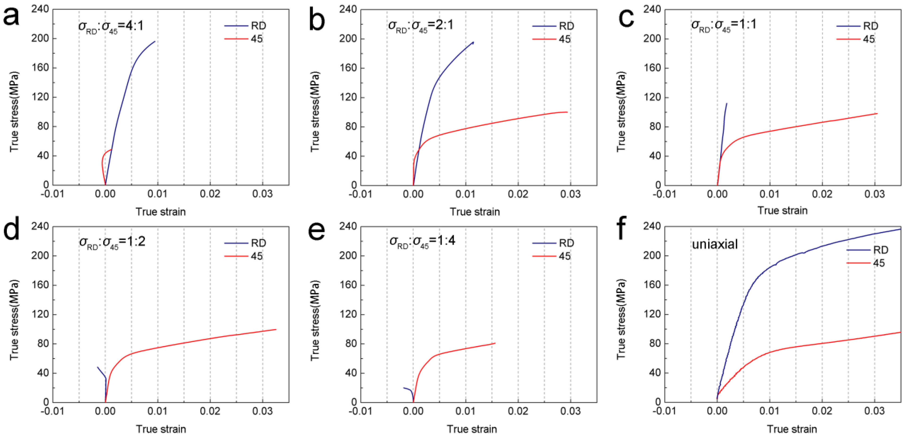
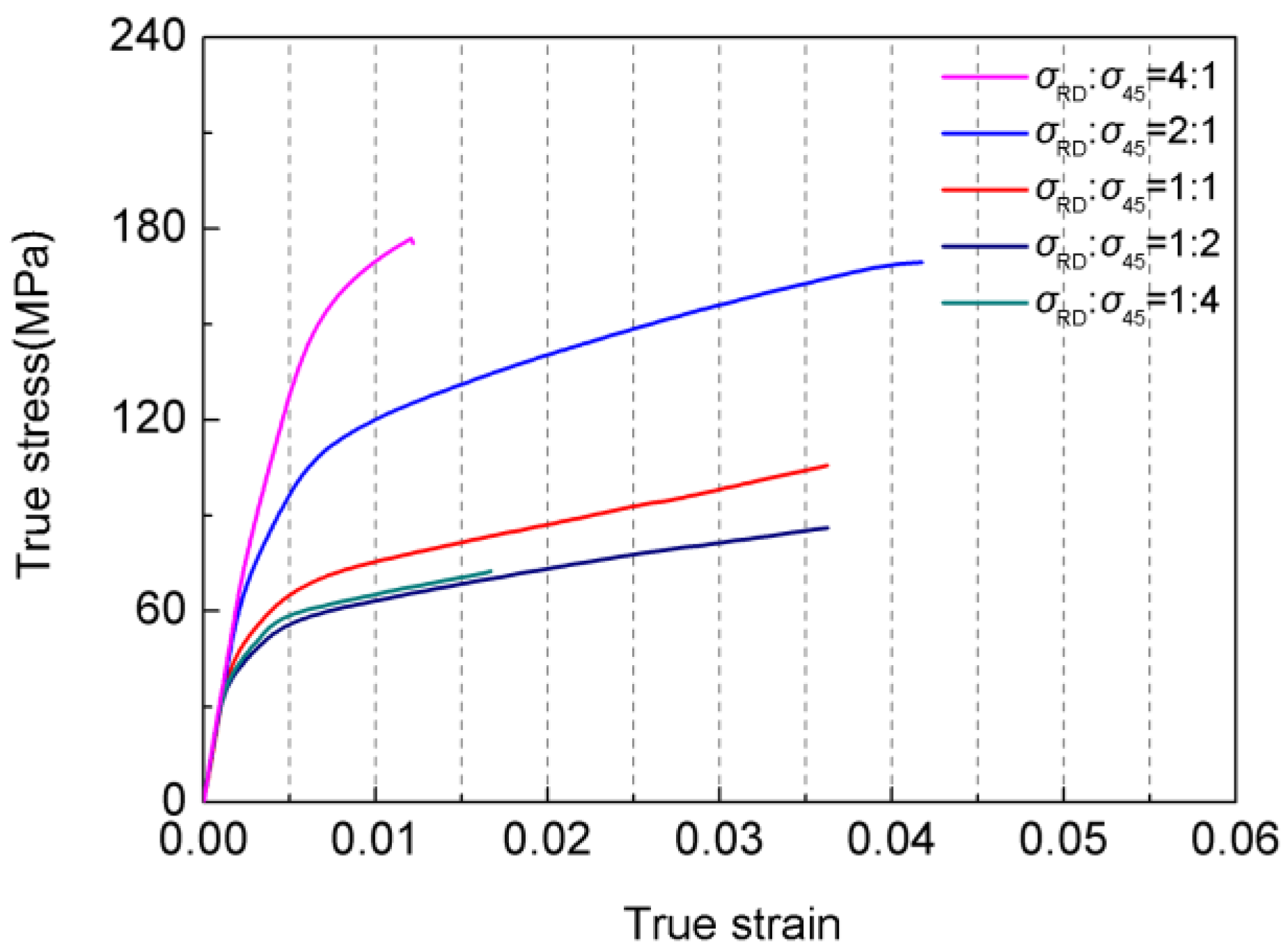
3.1. Mechanical Behavior

The true strain-stress curves for the broken samples subjected to biaxial tension and the uniaxial tension samples for strain levels up to 3% are depicted in Figure 3. Under biaxial stress with σ RD : σ 45   < 2:1, the 45° curve describes a state of tensile strain throughout, and the shape of the 45° curves as well as their yield stresses are similar to the result of performing a uniaxial tensile test along the 45° direction. For the stress ratio σ RD : σ 45 = 4:1, the 45° curves describe a state of compressive strain initially and a state of tensile strain at larger stress values. Compressive strain can be observed as well for the RD curve, for the ratios σ RD : σ 45 = 1:2 and 1:4. For σ RD : σ 45 = 1:1, evidence of tensile plastic strain is clearly visible on the 45° curve, but no yield plateau is observed on the RD curve. When σ RD : σ 45 > 1:1, a tensile strain is present for the RD curves, the shapes of which qualitatively resemble the result of a uniaxial tension along the RD.
The equivalent stress and equivalent strain are generally given by:
σ q = 3 2 σ ij d σ ij d
ε q = 2 3 d ε ij d ε ij
The equivalent stress and equivalent strain can be ascribed by the principal stress and principal strain as below:
σ q = σ x σ y 2 + σ y σ z 2 + σ z σ x 2 2
ε q = 2 9 ε x ε y 2 + ε y ε z 2 + ε z ε x 2
The biaxial tension can be seen as a plane-stress state. Hence, the equivalent stress can be calculated as:
σ q = σ x σ y 2 + σ y 2 + σ x 2 2
The calculations are shown in Figure 4. The yield stress of the equivalent stress-strain curve was found to decrease with decreasing stress ratio. For σ RD : σ 45 = 1:4, 1:2 and 1:1, the shapes of the equivalent stress-strain curves and yield stresses value resemble the results of a uniaxial tension along the 45° direction, whereas the yield stress and curve shape for σ RD : σ 45 = 4:1 resemble the result of a uniaxial tension along the RD. The sample under biaxial tension always show a lower strain [31,32,33].

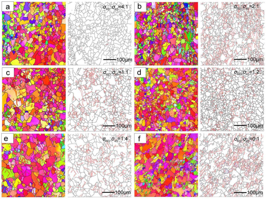
3.2. Twinning Behavior

The IPF maps for the samples in Section 3.1 with the stress ratios σ RD : σ 45 = 4:1, 2:1, 1:1, 1:2 1:4 and 0:1 is shown in Figure 5. The 10 1 ¯ 2 twins are observed, and the extension twins are found to cluster in particular grains. It seems that there are more twins for σ RD : σ 45 = 2:1, 1:1, 1:2 and 0:1 but fewer twins for σ RD : σ 45   = 4 : 1 . The measured 10 1 ¯ 2 TV fractions are tabulated along with the corresponding (see Figure 3 and Figure 4) RD strain, 45° strain and equivalent-strain (Equ-strain) in Table 1. The low TV fraction observed for the case of biaxial stress with σ RD : σ 45 = 4 : 1 was ascribed to limited plastic deformation. The TV fraction values for σ RD : σ 45 = 2 : 1 ,   1 : 1 ,   1 : 2 and 1:4 decreased with the decreasing stress ratio, and with plastic deformation of the RD transformation from positive to negative under the similar 45° and equivalent strain. In addition, the TV fractions for σ RD : σ 45 = 1 : 1 ,   1 : 2 and 1:4 were evidently lower than what was observed for the case of uniaxial tension ( σ RD : σ 45 = 1 : 0 ) at the same strain. However, the TV fraction for σ RD : σ 45 = 2 : 1 was higher than the uniaxial tension observation.
The textures under different biaxial stress ratio are displayed in Figure 6. Biaxial stress with σ RD : σ 45 = 1 : 4 caused a portion of c-axes on the right hemisphere to reorient to the left hemisphere, which can be ascribed to the reorient of the tension twinning. Specifically, the c-axis of grain for initial component was parallel to the 45° direction; The component induced by twinning was composed by the grain with (0002) poles almost perpendicular to this direction. Note that except for the case σ RD : σ 45 = 1 : 4 (Figure 6b), the twin component was not observed due to the low TV fraction.

4. Discussion

4.1. Twinning and Slip Behavior under Biaxial Tension
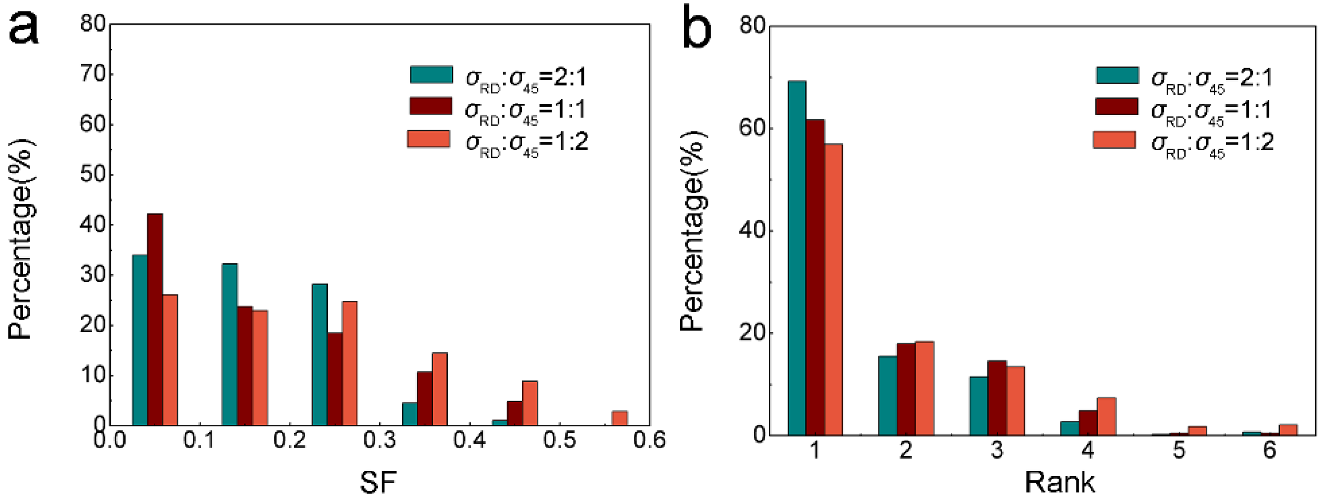
4.1.1. Schmid Factor Analysis of the 10 1 ¯ 2 Twinning System

There is a debate in the literature [17,34,35] concerning the extent to which activation of a given twin variant depends on its Schmid factor (SF). In order to quantitatively research the twinning behavior under biaxial tension, the SF for 10 1 ¯ 2 twinning under this condition was calculated. The present paper has employed the GSF modified by Xia et al. [36] for this purpose. This expression can be applied to any stress state. To arrive at the modified GSF, the stress intensity is introduced with the objective to normalize the stress tensor ( σ ¯ ).
σ ¯ = σ x σ y 2 + σ y σ z 2 + σ z σ x 2 + 6 τ x y 2 + τ y z 2 + τ z x 2 2
By introducing the stress intensity, the SF is a solid result that only correlates with the stress ratio, although the σ x ,   σ y can be arbitrary numbers. The modified GSF is calculated as Equation (4).
G S F = b T · σ · n / σ   ¯
The SFs for the activated 10 1 ¯ 2 twinning under biaxial tension with the stress ratios 2:1, 1:1 and 1:2 (see Figure 5) was calculated according to Equation (4) and ranked from 1 to 6, with the highest SF having rank 1. The distribution of SFs is shown in Figure 7a. The SF ranks and the associated percentage of experimentally observed twins are shown in Figure 7b. Under biaxial tension, the twin of rank 1 occurs much more frequently. The percentage of ranks 1 and 2 combine approximately 85% for σ RD : σ 45 = 2 : 1 , 80% for σ RD : σ 45 = 1 : 1 , and 75% for σ RD : σ 45 = 1 : 2 . These results show that most activation of 10 1 ¯ 2 twinning obeys Schmid’s law.

4.1.2. Contribution of the Twinning to Plastic Deformation

In order to clarify the contribution of the 10 1 ¯ 2 twinning for plasticity deformation, the strain accommodated by the activated 10 1 ¯ 2 twinning for similar equivalent strain under the conditions σ RD : σ 45 =   2 : 1 , 1 : 1 , and 1 : 2 was calculated. This strain may be computed as follows [17]:
ε t w i n = f t w i n · m ¯ · γ t w i n
where ε t w i n , f t w i n , m ¯ and γ t w i n represent the twinning strain, the volume fraction of twins, the average SF of the observed twin, and the characteristic twinning shear, respectively. For 10 1 ¯ 2 twinning in Mg alloys, ε t w i n is known to be 0.129. As described earlier, however, two factors, m ¯ and f t w i n , are significantly dependent on the stress ratio. m ¯ was 0.1347, 0.113 and 0.1957 for the stress ratios of σ RD : σ 45 = 2 : 1 , 1 : 1 and 1 : 2 , respectively. The twin volume fractions shown in Table 1 were used in the calculations. The results show that, 8% deformation is dominated by twinning under the stress ratio σ RD : σ 45 = 2 : 1 and 5% deformation was dominated by twinning for σ RD : σ 45 = 1:1 and 1:2. As the total strain is accommodated by twinning and slip, the strain accommodated by slip is equal to 1 minus the strain by twinning. Therefore, the plastic deformation under biaxial tension along RD and 45° was dominated by slip.

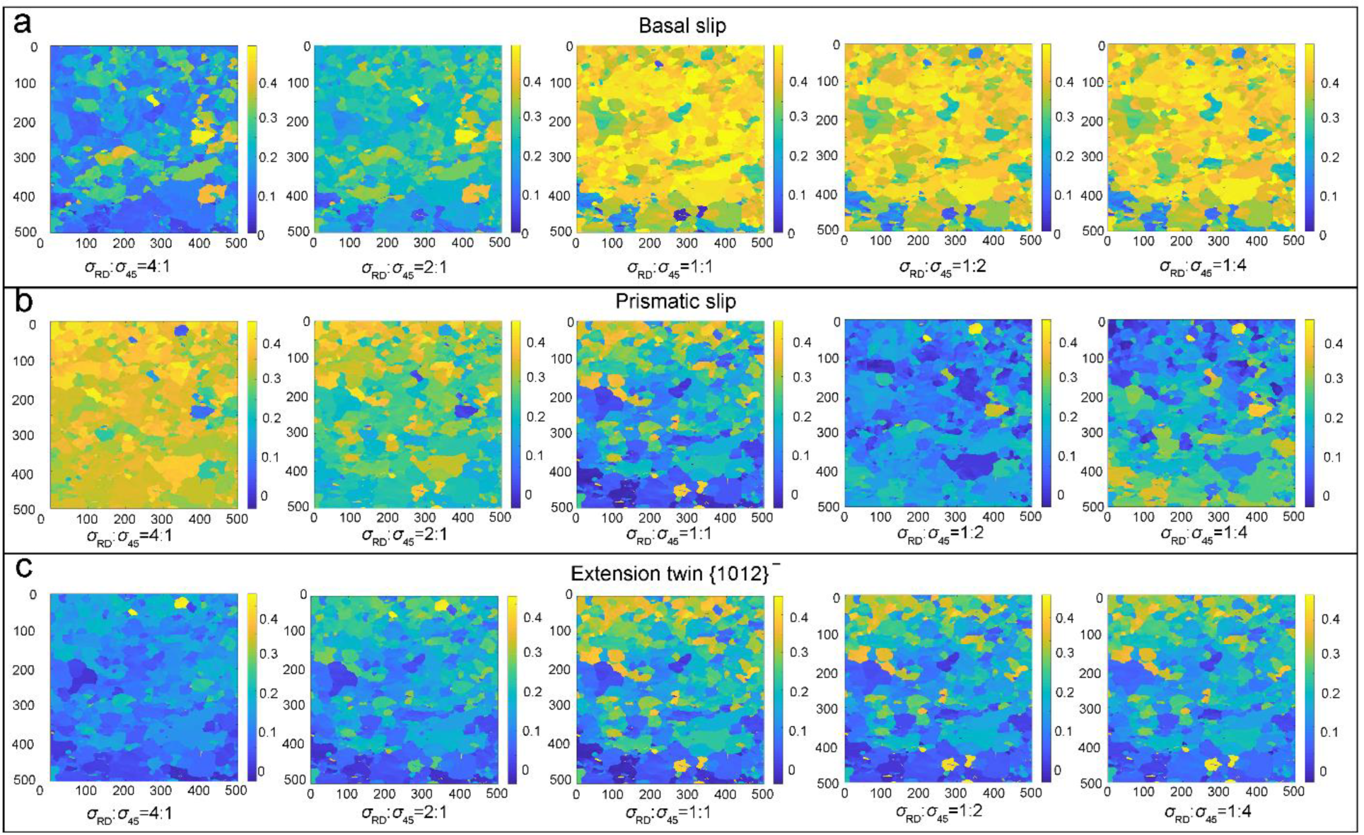
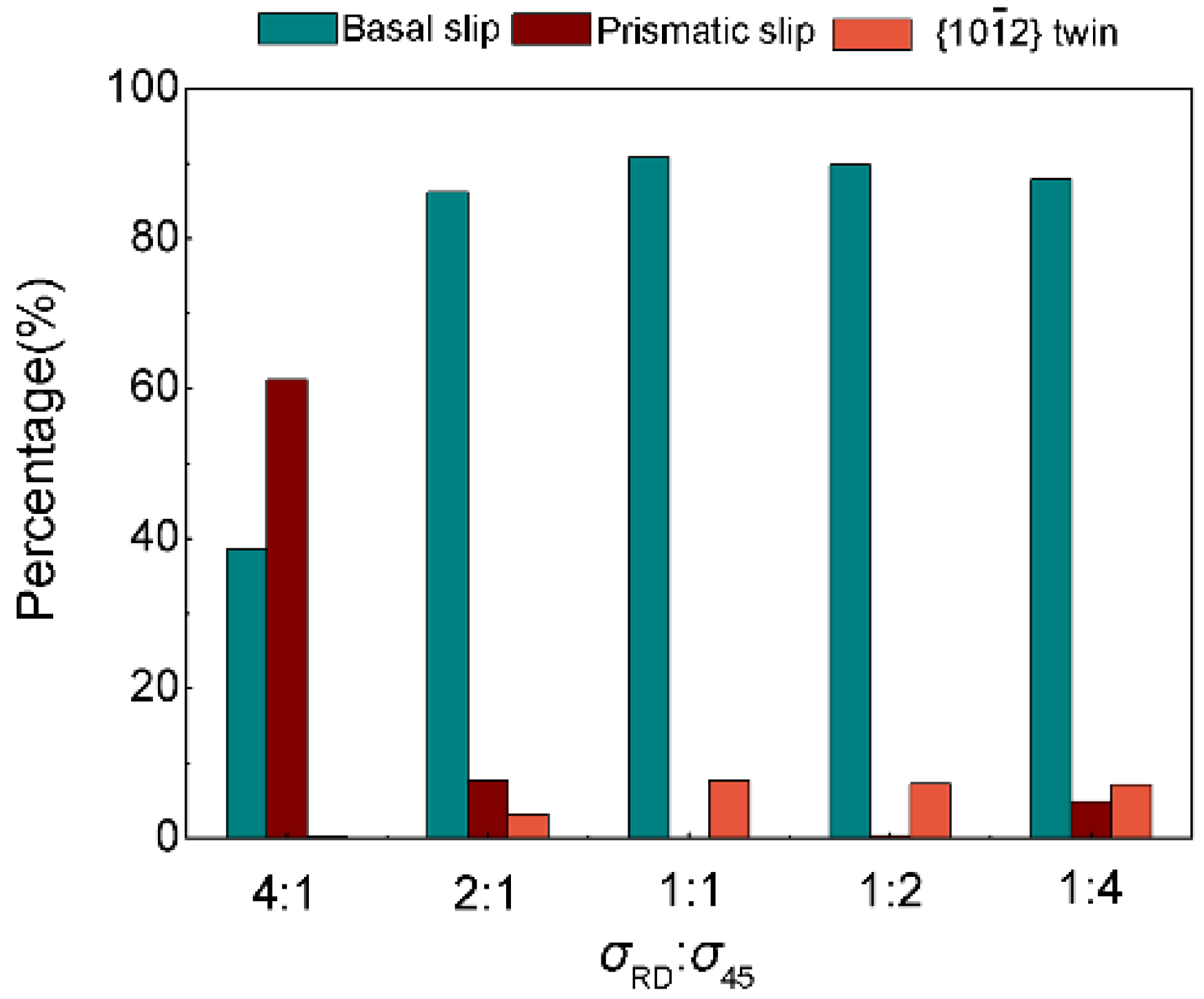
4.1.3. Activities of Slip Systems in the Deformation

The activation of slip and twinning was governed by the combined action of SF and CRSS, as the CRSS for different deformation modes vary significantly. The deformation mode with a minimum value of CRSS/SF is the dominant one.
The variation in SFs for basal slip, prismatic slip and 10 1 ¯ 2 twinning as a function of the crystallographic orientation for the initial texture with respect to biaxial stress ratio was calculated using the method in Section 4.1. Figure 8 shows the SFs varies with the relative spatial position in IPF map. Due to the polarity of twinning, the SF of the twin with a negative SF is seen as zero. Clearly, the SFs for basal slip are high for the biaxial stress ratio σ RD : σ 45   1. Conversely, the SFs for prismatic slip are high for σ RD : σ 45 > 1. The 10 1 ¯ 2 twinning always maintains a low SF under all biaxial stress ratios. For further comparison, the SF distribution for basal slip, prismatic slip and 10 1 ¯ 2 twinning under biaxial stress of σ RD : σ 45 =   4 : 1 , 2 : 1 , 1 : 1 , 1 : 2 , and 1 :   4 was shown in Figure 9. The SF of the prismatic slip increased with an increasing stress ratio along the RD. That is, the role of prismatic slip played in plasticity increases with a higher stress ratio along the RD. The SF for 10 1 ¯ 2 twinning was noted to increase with decreasing biaxial stress ratio. Hence, it is easy to understand the observed decrease in the TV fraction with the decreasing stress ratio.
Following the above analysis, CRSS/SF ratios were calculated for basal slip, prismatic slip and 10 1 ¯ 2 twinning to determine the predominant modes during biaxial tension [37]. The CRSS for basal slip (10 MPa):   10 1 ¯ 2 twinning (10 MPa): prismatic slip (20 MPa) is chosen in the present study according to research by Koike et al. [8]. The percentage of the grain, in which the most easily activation deformation modes is basal slip, prismatic slip, and 10 1 ¯ 2 twinning under biaxial tension is given in Figure 10. The fractions favoring basal slip and prismatic slip for the stress ratio σ RD : σ 45   = 4:1 reach 38% and 61%, respectively. The grains favoring basal slip increase significantly for σ RD : σ 45   < 4:1, reaching 91% at σ RD : σ 45   = 1:1. A very low percentage is noted to favor prismatic slip as the stress ratio decreases. Hence, both prismatic slip and basal slip will play an important role in deformation at the stress ratio σ RD : σ 45   = 4:1, whereas the contribution from basal slip will become the more important with a decrease in the stress ratio.

4.2. Effect of the Deformation Mechanism on the Flow Stress

The mechanical characteristics of stress–strain curves are known to originate from the detailed deformation mechanism [21]. As depicted in Section 3.1, the flow stress for tension along the 45° direction hardly varies with σ RD : σ 45 (stress ratios σ RD : σ 45 = 2:1, 1:1, 1:2 and 1:4 examined). Similarly, the flow stress of the RD curve for the biaxial stress ratios σ RD : σ 45 = 4:1, 2:1 and 1:1 also followed a similar trend, resembling the result of the RD uniaxial tension. It is well known that the dominates deformation mechanism during uniaxial tension along the RD was prismatic slip, whereas basal slip occurs when applying tension at an angle of 45° to ND and TD [6,38,39]. In the case of biaxial stress with σ RD : σ 45 = 1:1, 1:2 and 1:4, the deformation along the 45° direction was dominated by basal slip, which can be ascribed to the similar levels of flow stress. However, under those conditions, the stress along the RD is too low to support activation of prismatic slip. For a stress ratio σ RD : σ 45 = 4:1, the deformation along the RD was dominated by prismatic slip. It is noted that for the condition σ RD : σ 45   = 4:1, the strain along the 45° direction was initially compressive. With the increase in stress, the strain turned tensile, which can be ascribed to the activation of basal slip.
The equivalent yield stress for the case of biaxial tension is determined by the resolved shear stress σ R S S , that is CRSS/SF, of the deformation mechanism. The σ R S S values for the activated deformation mechanism during biaxial tension were averaged and named σ ¯ R S S . Using the data in Section 4.2, we obtained the ratio of σ ¯ R S S for σ RD : σ 45 = 1:0, 4:1, 2:1, 1:1, and 1:2. The values of σ ¯ 4 : 1 :   σ ¯ 1 : 4 , σ ¯ 2 : 1 :   σ ¯ 1 : 4 , σ ¯ 1 : 1 :   σ ¯ 1 : 4 , σ ¯ 1 : 2 :   σ ¯ 1 : 4 were 1.67, 1.54, 0.94, 1.01, respectively, which has the same tendency with the yield stress by equivalent stress–strain curve. Note that this method can only predict the tendency but not the actual values, as a consequence of the controversy concerning the CRSS of basal slip, prismatic slip and twinning. In fact, for σ RD : σ 45   = 1:1, 1:2 and 1:4, the essential reason for yielding behavior is basal slip. Hence, a similar equivalent yield stress value is easy to understand. However, with the increase in the biaxial stress ratio, the contribution of the prismatic slip will increase, which makes the yield stress increase gradually and approach the values obtained for uniaxial tension along the RD.

5. Conclusions

In this work, the biaxial deformation behavior of a Mg AZ31 sheet along the RD and the diagonal direction (‘45° direction’) between ND and TD was comprehensively researched. The impacts of the stress ratio along the RD and 45° direction on the mechanical response, twinning behavior, texture and slip behavior were investigated. The activation of 10 1 ¯ 2 twinning was found to obey Schmid’s law. The 8% deformation is dominated by twinning for σ RD : σ 45 = 2:1 and 5% for σ RD : σ 45 = 1:1 and 1:2. The activation of twinning generate a twin texture with the c-axes of grains largely parallel the 45° between TD and ND. The twin volume fraction for σ RD : σ 45 = 1 : 1 ,   1 : 2 and 1:4 was evidently lower the fraction observed for the case of uniaxial tension ( σ RD : σ 45 = 1 : 0 ) at the same strain. The TV fraction for σ RD : σ 45 = 2 : 1 is higher than the uniaxial tension result. The deformation induced by the biaxial tension was dominated by basal slip and prismatic slip, and grains favoring basal slip were found to increase in number upon decreasing the biaxial stress ratio. These differences in twinning and slip characteristics introduced different flow stresses, and could be explained successfully by incorporating existing theories on the variation of the relative activities of twinning, basal slip and prismatic slip during plastic deformation.

Author Contributions

Y.C.: Investigation, Writing—Original Draft, Writing—Review and Editing, Visualization. J.M.: Investigation, Data Curation, Writing—Original Draft, Writing—Review and Editing, Visualization. Y.F.: Investigation, Data Curation, Writing—Original Draft, Visualization. Q.H.: Original Draft, Visualization. L.Z.: Writing—Original Draft, Writing—Review and Editing. Y.X.: Conceptualization, Validation, Formal analysis, Writing—Original Draft, Writing—Review and Editing, Project administration, Funding acquisition. G.C.: Conceptualization, Validation, Supervision, Formal analysis. P.W.: Methodology, Writing—Original Draft, Writing—Review and Editing, Supervision. Q.L.: Writing—Review and Editing, Supervision. All authors have read and agreed to the published version of the manuscript.

Funding

This research was funded by the National Natural Science Foundation of China (No. 52201123 and No. 52071039), China Postdoctoral Science Foundation (No. 2022M721582), and Natural Science Foundation of Jiangsu Province (No. BK20202010), Jiangsu Funding Program for Excellen Postdoctoral Talent(No. 2022ZB380).

Data Availability Statement

Not applicable.

Conflicts of Interest

The authors declare no conflict of interest.

References

  1. Kuji, C.; Soyama, H. Mechanical Surface Treatment of Titanium Alloy Ti6Al4V Manufactured by Direct Metal Laser Sintering Using Laser Cavitation. Metals 2023, 13, 181. [Google Scholar] [CrossRef]
  2. Li, Y.; Han, T.; Chu, Z.; Xue, C.; Yang, Q.; Zhao, X.; Gao, H. Effect of Loading Direction on the Tensile Properties and Texture Evolution of AZ31 Magnesium Alloy. Crystals 2021, 11, 1193. [Google Scholar] [CrossRef]
  3. Pérez, P.; Medina, J.; Vega, M.F.; Garcés, G.; Adeva, P. Control of the Microstructure in a Al5Co15Cr30Fe25Ni25 High Entropy Alloy through Thermo-Mechanical and Thermal Treatments. Metals 2023, 13, 180. [Google Scholar] [CrossRef]
  4. Čapek, J.; Panzner, T.; Sofinowski, K.; Drozdenko, D.; Máthis, K. In Situ Neutron Diffraction and Acoustic Emission during the Biaxial Loading of AZ31 Alloy. In Magnesium Technology 2018; Orlov, D., Joshi, V., Solanki, K.N., Neelameggham, N.R., Eds.; Springer International Publishing: Cham, Switzerland, 2018; pp. 199–202. [Google Scholar]
  5. Thirumalai, R.; Senthilkumaar, J.S.; Selvarani, P.; Ramesh, S. Machining characteristics of Inconel 718 under several cutting conditions based on Taguchi method. Proc. Inst. Mech. Eng. Part C J. Mech. Eng. Sci. 2012, 227, 1889–1897. [Google Scholar] [CrossRef]
  6. Wang, H.; Wu, P.D.; Gharghouri, M.A. Effects of basal texture on mechanical behaviour of magnesium alloy AZ31B sheet. Mater. Sci. Eng. A 2010, 527, 3588–3594. [Google Scholar] [CrossRef]
  7. Chun, Y.B.; Davies, C.H.J. Investigation of Prism <a> Slip in Warm-Rolled AZ31 Alloy. Metall. Mater. Trans. A 2011, 42, 4113–4125. [Google Scholar]
  8. Zhao, B.; Wu, W.; Zhi, J.; Su, C.; Yao, T. Effect of CeO2 Content on Melting Performance and Microstructure of CaO-Al2O3-SiO2-MgO Refining Slag. Metals 2023, 13, 179. [Google Scholar] [CrossRef]
  9. Zhang, J.; Xin, S.; Zhang, Y.; Guo, P.; Sun, H.; Li, T.; Qin, C. Effects of Elements on the Microstructure and Mechanical Properties of AlCoCrFeNiTi High-Entropy Alloys. Metals 2023, 13, 178. [Google Scholar] [CrossRef]
  10. Sun, X.; Liu, P.; Jiang, Z.; Yang, Y.; Wang, Z.; Mu, Z. Analysis of Design Method and Mechanical Properties of Plug-In Composite Shear Wall. Metals 2023, 13, 177. [Google Scholar] [CrossRef]
  11. Máthis, K.; Čapek, J.; Zdražilová, Z.; Trojanová, Z. Investigation of tension—Compression asymmetry of magnesium by use of the acoustic emission technique. Mater. Sci. Eng. A 2011, 528, 5904–5907. [Google Scholar] [CrossRef]
  12. Máthis, K.; Csiszár, G.; Čapek, J.; Gubicza, J.; Clausen, B.; Lukáš, P.; Vinogradov, A.; Agnew, S.R. Effect of the loading mode on the evolution of the deformation mechanisms in randomly textured magnesium polycrystals—Comparison of experimental and modeling results. Int. J. Plast. 2015, 72, 127–150. [Google Scholar] [CrossRef]
  13. Xiong, Y.; Yu, Q.; Jiang, Y. Deformation of extruded ZK60 magnesium alloy under uniaxial loading in different material orientations. Mater. Sci. Eng. A 2018, 710, 206–213. [Google Scholar] [CrossRef]
  14. Barnett, M.R.; Ghaderi, A.; da Fonseca, J.Q.; Robson, J.D. Influence of orientation on twin nucleation and growth at low strains in a magnesium alloy. Acta Mater. 2014, 80, 380–391. [Google Scholar] [CrossRef]
  15. Ma, Q.; El Kadiri, H.; Oppedal, A.L.; Baird, J.C.; Li, B.; Horstemeyer, M.F.; Vogel, S.C. Twinning effects in a rod-textured AM30 Magnesium alloy. Int. J. Plast. 2012, 29, 60–76. [Google Scholar] [CrossRef]
  16. Chen, J.; Zhu, M.; Gan, M.; Wang, X.; Gu, C.; Tu, J. Rapid Electrodeposition and Corrosion Behavior of Zn Coating from a Designed Deep Eutectic Solvent. Metals 2023, 13, 172. [Google Scholar] [CrossRef]
  17. Hong, S.-G.; Park, S.H.; Lee, C.S. Role of {10–12} twinning characteristics in the deformation behavior of a polycrystalline magnesium alloy. Acta Mater. 2010, 58, 5873–5885. [Google Scholar] [CrossRef]
  18. Lou, X.Y.; Li, M.; Boger, R.K.; Agnew, S.R.; Wagoner, R.H. Hardening evolution of AZ31B Mg sheet. Int. J. Plast. 2007, 23, 44–86. [Google Scholar] [CrossRef]
  19. Chapuis, A.; Wang, B.; Liu, Q. A comparative study between uniaxial compression and plane strain compression of Mg–3Al–1Zn alloy using experiments and simulations. Mater. Sci. Eng. A 2014, 597, 349–358. [Google Scholar] [CrossRef]
  20. Wang, H.; Raeisinia, B.; Wu, P.D.; Agnew, S.R.; Tomé, C.N. Evaluation of self-consistent polycrystal plasticity models for magnesium alloy AZ31B sheet. Int. J. Solids Struct. 2010, 47, 2905–2917. [Google Scholar] [CrossRef]
  21. Wang, B.; Xin, R.; Huang, G.; Liu, Q. Effect of crystal orientation on the mechanical properties and strain hardening behavior of magnesium alloy AZ31 during uniaxial compression. Mater. Sci. Eng. A 2012, 534, 588–593. [Google Scholar] [CrossRef]
  22. Knezevic, M.; Levinson, A.; Harris, R.; Mishra, R.K.; Doherty, R.D.; Kalidindi, S.R. Deformation twinning in AZ31: Influence on strain hardening and texture evolution. Acta Mater. 2010, 58, 6230–6242. [Google Scholar] [CrossRef]
  23. Wang, H.; Wu, P.D.; Wang, J.; Tomé, C.N. A crystal plasticity model for hexagonal close packed (HCP) crystals including twinning and de-twinning mechanisms. Int. J. Plast. 2013, 49, 36–52. [Google Scholar] [CrossRef]
  24. Xie, S.; Yuan, X.; Liu, F.; Zhao, B. Control of Copper Content in Flash Smelting Slag and the Recovery of Valuable Metals from Slag—A Thermodynamic Consideration. Metals 2023, 13, 153. [Google Scholar] [CrossRef]
  25. Molodov, K.D.; Al-Samman, T.; Molodov, D.A.; Gottstein, G. On the role of anomalous twinning in the plasticity of magnesium. Acta Mater. 2016, 103, 711–723. [Google Scholar] [CrossRef]
  26. Luo, J.R.; Godfrey, A.; Liu, W.; Liu, Q. Twinning behavior of a strongly basal textured AZ31 Mg alloy during warm rolling. Acta Mater. 2012, 60, 1986–1998. [Google Scholar] [CrossRef]
  27. Molodov, K.D.; Al-Samman, T.; Molodov, D.A.; Gottstein, G. Mechanisms of exceptional ductility of magnesium single crystal during deformation at room temperature: Multiple twinning and dynamic recrystallization. Acta Mater. 2014, 76, 314–330. [Google Scholar] [CrossRef]
  28. Tomlinson, P.; Azizi-Alizamini, H.; Poole, W.J.; Sinclair, C.W.; Gharghouri, M.A. Biaxial Deformation of the Magnesium Alloy AZ80. Metall. Mater. Trans. A 2013, 44, 2970–2983. [Google Scholar] [CrossRef]
  29. Kuwabara, T.; Ikeda, S.; Kuroda, K. Measurement and analysis of differential work hardening in cold-rolled steel sheet under biaxial tension. J. Mater. Process. Technol. 1998, 80–81, 517–523. [Google Scholar] [CrossRef]
  30. Cheng, Y.; Fu, Y.; Xin, Y.; Chen, G.; Wu, P.; Huang, X.; Liu, Q. 10 1 ¯ 2 twinning behavior under biaxial tension of Mg–3Al–1Zn plate. Int. J. Plast. 2020, 132, 102754. [Google Scholar] [CrossRef]
  31. Kim, H.L.; Bang, W.K.; Chang, Y.W. Effect of initial texture on deformation behavior of AZ31 magnesium alloy sheets under biaxial loading. Mater. Sci. Eng. A-Struct. Mater. Prop. Microstruct. Process. 2012, 552, 245–251. [Google Scholar] [CrossRef]
  32. Van Petegem, S.; Wagner, J.; Panzner, T.; Upadhyay, M.V.; Trang, T.T.T.; Van Swygenhoven, H. In-situ neutron diffraction during biaxial deformation. Acta Mater. 2016, 105, 404–416. [Google Scholar] [CrossRef]
  33. Steglich, D.; Jeong, Y.; Andar, M.O.; Kuwabara, T. Biaxial deformation behaviour of AZ31 magnesium alloy: Crystal-plasticity-based prediction and experimental validation. Int. J. Solids Struct. 2012, 49, 3551–3561. [Google Scholar] [CrossRef]
  34. Godet, S.; Jiang, L.; Luo, A.; Jonas, J. Use of Schmid factors to select extension twin variants in extruded magnesium alloy tubes. Scr. Mater. 2006, 55, 1055–1058. [Google Scholar] [CrossRef]
  35. Jonas, J.J.; Mu, S.; Al-Samman, T.; Gottstein, G.; Jiang, L.; Martin, Ė. The role of strain accommodation during the variant selection of primary twins in magnesium. Acta Mater. 2011, 59, 2046–2056. [Google Scholar] [CrossRef]
  36. Xia, D.; Chen, X.; Huang, G.; Jiang, B.; Tang, A.; Yang, H.; Gavras, S.; Huang, Y.; Hort, N.; Pan, F. Calculation of Schmid factor in Mg alloys: Influence of stress state. Scr. Mater. 2019, 171, 31–35. [Google Scholar] [CrossRef]
  37. Hutchinson, W.B.; Barnett, M.R. Effective values of critical resolved shear stress for slip in polycrystalline magnesium and other hcp metals. Scr. Mater. 2010, 63, 737–740. [Google Scholar] [CrossRef]
  38. Yu, H.; Li, C.; Xin, Y.; Chapuis, A.; Huang, X.; Liu, Q. The mechanism for the high dependence of the Hall-Petch slope for twinning/slip on texture in Mg alloys. Acta Mater. 2017, 128, 313–326. [Google Scholar] [CrossRef]
  39. Zhang, J.; Xi, G.; Wan, X.; Fang, C. The dislocation-twin interaction and evolution of twin boundary in AZ31 Mg alloy. Acta Mater. 2017, 133, 208–216. [Google Scholar] [CrossRef]
Figure 1. (a) RD, TD, 45° and the cruciform specimen in the hot-rolled plate, (b) image of cruciform specimen with dimensions indicated.
Metals 13 00845 g001
Figure 2. (a) ND inverse pole figure map and (b) pole figures of AZ31 plate after annealing at 400 °C for 2 h.
Metals 13 00845 g002
Figure 3. Ture stress-strain curves under biaxial stress: σ RD : σ 45 = (a) 4:1, (b) 2:1, (c) 1:1, (d) 1:2, (e) 1:4 and (f) 1:0 and 0:1.
Metals 13 00845 g003
Figure 4. Equivalent stress-strain curves under biaxial tension of σ RD : σ 45 = 4:1, 2:1, 1:1, 1:2 and 1:4.
Metals 13 00845 g004
Figure 5. Inverse pole figure maps of uniaxial and biaxial tension with a 1.5% strain along the ND: σ RD : σ 45 = (a) 4:1, (b) 2:1, (c) 1:1, (d) 1:2, (e) 1:4 and (f) 0:1.
Metals 13 00845 g005
Figure 6. Pole figures for specimens after uniaxial and biaxial tension with σ RD : σ 45 = (a) 4:1, (b) 2:1, (c) 1:1, (d) 1:2 and (e) 1:4.
Metals 13 00845 g006
Figure 7. (a) Distribution of SF and (b) SF rank and its percentage of experimentally observed twins SF rank of experimentally observed 10 1 ¯ 2 twin for σ RD : σ 45 = 2:1, 1:1, and 1:2.
Metals 13 00845 g007
Figure 8. Schmid factor (SF) as a function of the relative spatial position in EBSD maps for (a) basal slip, (b) prismatic slip and (c) 10 1 ¯ 2 twinning under biaxial stress of σ RD : σ 45 = 4:1, 2:1, 1:1, 1:2, and 1:4.
Metals 13 00845 g008
Figure 9. Distribution of SF for basal slip, prismatic slip and 10 1 ¯ 2 twinning under biaxial stress of σ RD : σ 45 = (a) 4:1, (b) 2:1, (c) 1:1, (d) 1:2, and (e) 1:4.
Metals 13 00845 g009
Figure 10. Fractions of grains favoring basal slip, prismatic slip, and 10 1 ¯ 2 twinning during under biaxial stress of σ RD : σ 45 = 4:1, 2:1, 1:1, 1:2, and 1:4. The used CRSS ratio of basal slip: 10 1 ¯ 2 twinning: prismatic slip is 1:1:2.
Metals 13 00845 g010
Table 1. RD strain, 45° strain, equivalent strain, and twin volume fraction of the broken samples under σ RD : σ 45 = 4:1, 2:1, 1:1, 1:2, 1:4 and 0:1.
σ RD : σ 45 4:12:11:11:21:40:1
RD strain0.449%0.79%0%−0.16%−0.5%_
45° strain0.11%2.85%2.87%3.05%2.87%3%
Equ-strain0.7%3.7%3.38%3.38%3.5%3%
TV0.831%18.9%12.3%7%8.8%15.7%
Disclaimer/Publisher’s Note: The statements, opinions and data contained in all publications are solely those of the individual author(s) and contributor(s) and not of MDPI and/or the editor(s). MDPI and/or the editor(s) disclaim responsibility for any injury to people or property resulting from any ideas, methods, instructions or products referred to in the content.

