Article

Room- and High-Temperature Fatigue Strength of the T5 and Rapid T6 Heat-Treated AlSi10Mg Alloy Produced by Laser-Based Powder Bed Fusion

Department of Industrial Engineering (DIN), Alma Mater Studiorum, University of Bologna, Viale Risorgimento 4, 40136 Bologna, Italy
*
Author to whom correspondence should be addressed.
Metals 2023, 13(2), 263; https://doi.org/10.3390/met13020263
Submission received: 5 January 2023 / Revised: 20 January 2023 / Accepted: 26 January 2023 / Published: 29 January 2023
(This article belongs to the Special Issue Mechanical Behaviors and Damage Mechanisms of Metallic Materials)

Abstract

:
The AlSi10Mg alloy produced by laser-based powder bed fusion (L-PBF) is widely used to produce high-value-added structural parts subjected to cyclic mechanical loads at high temperatures. The paper aims to widen the knowledge of the room- and high-temperature (200 °C) fatigue behavior of the L-PBF AlSi10Mg alloy by analyzing the fully reversed rotating bending test results on mechanically polished specimens. Two heat-treated conditions are analyzed: T5 (direct artificial aging: 4 h at 160 °C) and novel T6R (rapid solution: 10 min at 510 °C, artificial aging: 6 h at 160 °C). The study highlights that (i) the T6R alloy is characterized by higher fatigue strength at room (108 MPa) and high temperatures (92 MPa) than the T5 alloy (92 and 78 MPa, respectively); (ii) thermal exposure at 200 °C up to 17 h does not introduce macroscopical microstructural variation; (iii) fracture surfaces of the room- and high-temperature-tested specimens show comparable crack initiation, mostly from sub-superficial gas and keyhole pores, and failure propagation mechanisms. In conclusion, the L-PBF AlSi10Mg alloy offers good cyclic mechanical performances under various operating conditions, especially for the T6R alloy, and could be considered for structural components operating at temperatures up to 200 °C.

1. Introduction

Laser-based powder bed fusion (L-PBF) technology offers several advantages over conventional processing, providing unique opportunities for component design to enhance mechanical performance and reduce the environmental impact by producing strength-optimized structures [1,2]. Heat sinks, engine and gas turbine parts, and aerodynamic components are a few of the possible high-value-added parts manufactured by L-PBF technology [3,4]. In particular, the AlSi10Mg alloy represents an up-and-coming solution for producing structural components: its near-eutectic composition, high powder laser absorption, and narrowed solidification range ensure good flowability and crack-free solidification compared to other Al cast alloys, easing L-PBF printing [5,6,7].
The as-built (AB) L-PBF AlSi10Mg alloy has an ultrafine microstructure consisting of supersatured α-Al cells and a Si-rich eutectic phase, which solidifies within a melt pool (MP) structure according to the adopted layer-by-layer deposition and scanning strategy [2,4]. The strengthening mechanisms derived from this peculiar microstructure promote high hardness and tensile strength values at the expense of ductility [8]. In particular, the interconnected eutectic Si network ensures high work hardening and tensile strength, but the brittleness of the hard Si phase and poor cohesion with the soft Al cells promote low-strain failure [9].
Instead, an optimal balance between the static mechanical properties is essential for improving fatigue performance in the structural component. High yield strength and ductility improve fatigue strength; they mitigate, in fact, the adverse effects of the local stress intensification factor at the defect tip and make the component less susceptible to fatigue crack initiation [2,10]. For this reason, several authors focused on optimizing post-processing heat treatments to overcome the limitations of the AB alloy, thus increasing fatigue strength [10,11,12,13,14,15,16,17,18]. In particular, the T6 heat treatment was evaluated as the most efficient heat treatment to increase the cyclic mechanical response of the L-PBF AlSi10Mg as the result of residual stress relieving, high strength–ductility balance, and microstructural homogenization [10,13,17]. It consists of a solution (SHT) step, which dissolves the intermetallics formed during solidification and releases Mg and Si into the Al matrix, followed by rapid quenching from the solution temperature (TSHT), usually performed in water (T ≈ 60 °C), to form a supersaturated Al solid solution. Finally, artificial aging (AA) promotes the fine precipitation of the β-Mg2Si precursor phases and nanosized Si particles [19,20]. After applying the T6 heat treatment, the microstructural anisotropy of the AB alloy disappears; the eutectic Si network evolves into a uniform distribution of spheroidal Si particles throughout the Al matrix, characterized by a more isotropic mechanical behavior and excellent ductility and toughness [21,22,23]. During the SHT step, Si particle growth occurs for coalescence induced by diffusion-driven phenomena and governed by solution parameters (TSHT and solution soaking time (tSHT)), which profoundly influence the Si particle features [7,18].
Brandl et al. [24] and Domfang Ngnekou et al. [13] extensively reported improving effects of the T6 heat treatment on fatigue performance, explaining it through the evolution of the eutectic Si network and the increase in resistance to crack initiation due to the higher cohesion between hard Si spheroidal particles and the soft Al matrix. Zhang et al. [18] also supported the Si particles’ leading role, analyzing the influence of their morphology, size, and distribution on the fatigue performances of the heat-treated L-PBF AlSi10Mg alloy. In particular, the detrimental effects of the coarser Si particles in stress intensification at the crack tip were related to loss of coherence at the Al/Si interface.
Even though the fatigue properties of the L-PBF AlSi10Mg parts have been the subject of an increasing investigation inherent to room-temperature fatigue properties, the effects of the high temperatures on the cyclic mechanical response have been quite completely neglected [2]. The progressive loss of the strengthening mechanisms above 200 °C due to the low thermal stability of the L-PBF AlSi10Mg alloy can limit the use in producing components directly or indirectly exposed to high temperatures. In particular, high-tech structural components in the transportation and energy industry are subjected to cyclic mechanical loads over a wide range of temperature distribution and mechanical load conditions [5]. Therefore, evaluating the effects of high temperatures on fatigue resistance is essential, particularly given the limited information in the literature [25,26,27].
Scope of the Paper
The present study aims to widen the knowledge of the relationships between room- and high-temperature fatigue behavior, microstructural features, and residual stresses of the L-PBF AlSi10Mg alloy and assess the main fracture mechanisms using fractographic analyses. In particular, based on previous static mechanical property characterization [28,29], full reversal rotating bending tests at room temperature and 200 °C were performed on specimens submitted to an optimized direct aging treatment (4 h at 160 °C), hereafter T5, and to a novel T6 heat treatment (SHT at 510 °C for 10 min and AA at 160 °C for 6 h), hereafter T6R, using a staircase method.

2. Materials and Methods

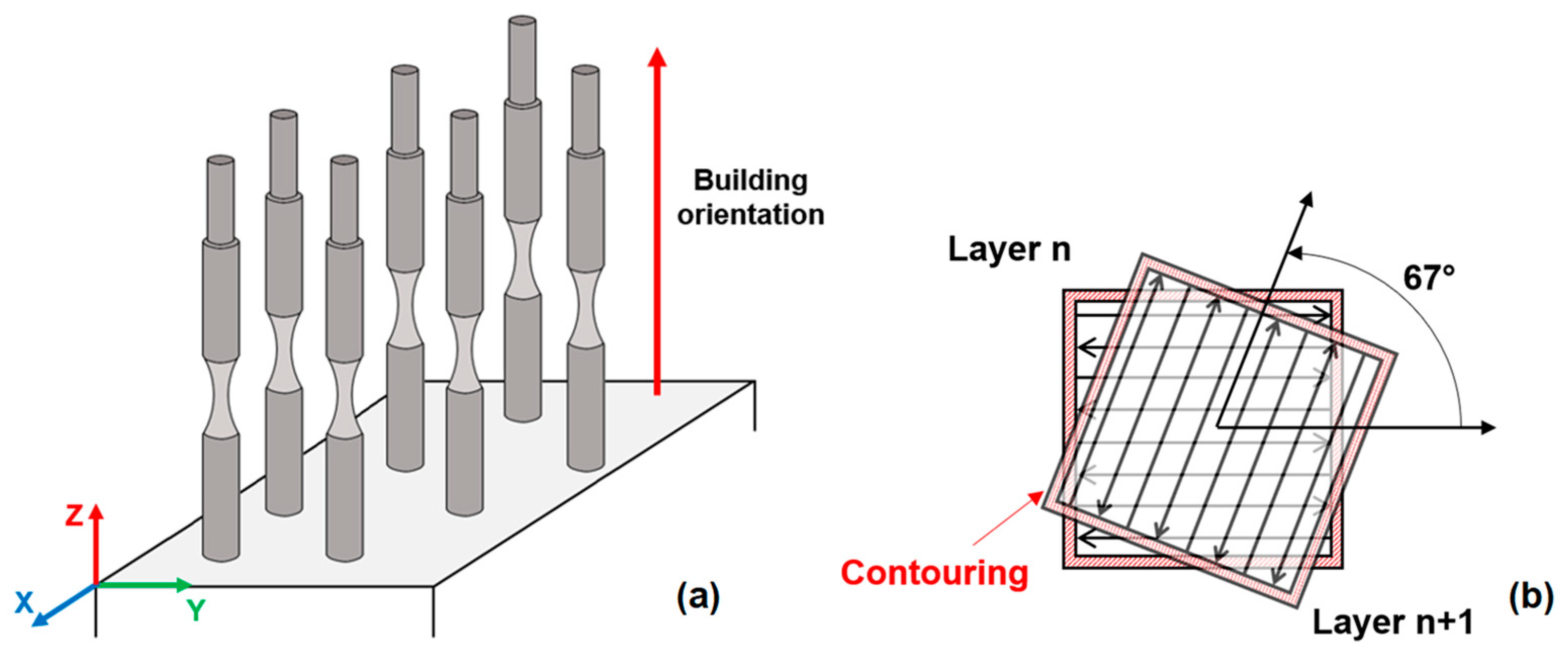
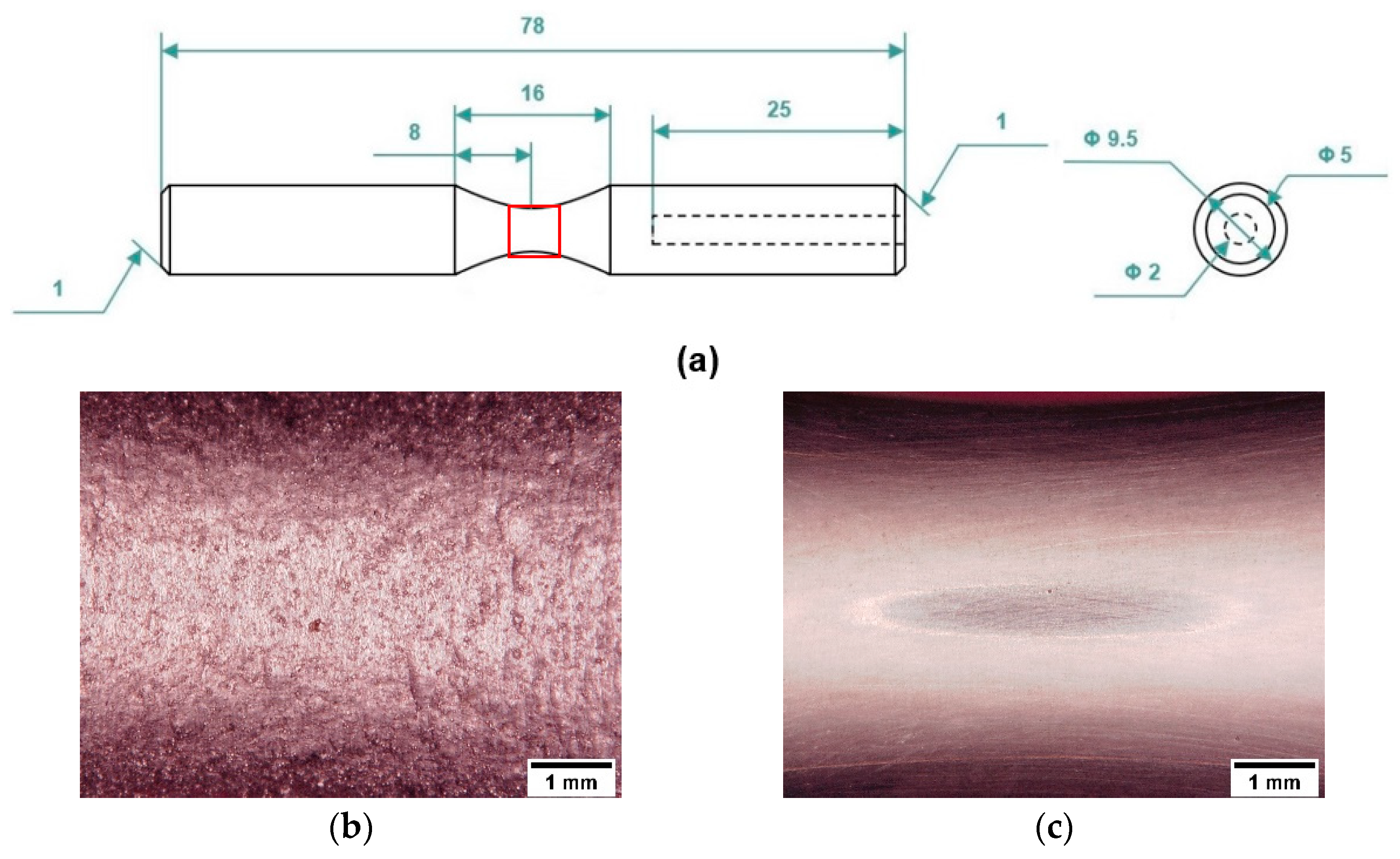
2.1. Specimen Production and Characterization

Near-net-shape specimens were printed with the longitudinal axis perpendicular to the platform, as schematically shown in Figure 1a, to reduce industrial costs [2,3] and consider the worst-case scenario in terms of mechanical strength [16,17]. An SLM500 system (SLM Solutions, Lübeck, Germany), characterized by a build chamber of 280 × 500 × 350 mm3 and four Yttrium fiber lasers operating in parallel, printed the fatigue specimens. The build chamber was filled with high-purity Ar gas to reduce the O2 level to 0.2 vol.%, and a 150 °C heated-platform temperature was used to reduce the thermal gradient during printing [22]. The process parameters were set as 350 W laser power, 1150 mm/s scan speed, 170 μm hatch distance, and 50 μm layer thickness. A bidirectional stripe scan strategy of 67° counter-clockwise rotation between subsequent layers was employed to increase the density and microstructural isotropy of the L-PBF-produced parts [30]. Remelted contour zone strategy was used at the end of each scanning to improve the surface quality of the specimens (Figure 1b).
The gas-atomized powder diameter ranged from 20 to 63 µm. The chemical composition of the L-PBF-produced specimens was checked using a glow discharge optical emission spectroscope (GD-OES) (GDA 650, Spectruma Analytik GmbH, Hof in Bayern, Germany) according to ISO 14707:2021. The instrument uses a Grimm-style glow discharge lamp in DC mode to analyze an area of about 5 mm2. The chemical compositions agree with the nominal composition of the AlSi10Mg alloy reported in the EN AC-43000 designation (Table 1).

2.2. Heat Treatment and Specimen Preparation

The fatigue specimens were subjected to optimized T5 and novel rapid T6R heat treatments, whose parameters are reported in Table 2. More details on the optimization of heat treatment parameters can be found in the Authors’ previous scientific article [28].
Near-net shape specimens were made with a 0.2 mm allowance on the gauge section and manually polished with emery paper from 250 to 1200 grit to ensure the geometric and dimensional tolerances required for the hourglass fatigue specimens shown in Figure 2a, consistent with ISO 1143:2021. A final polishing step with 2500 grit emery paper was performed in the direction parallel to the specimen axis to remove any circumferential marks (Figure 2b,c). The gauge section of the specimens was polished to consider near-net-shape surfaces in high-technological applications that require extremely low and controlled roughness [16,31,32].
The roughness was evaluated on all the tested specimens using stylus profilometry (Hommelwerke T2000, Schwenningen, Germany, radius of curvature of the stylus tip equal to 5 μm) on the grip section, which was polished by the same steps employed for the gauge length and used as a reference. A set of 8 measurements along the specimen longitudinal axis, spaced 45° around the circumference, were performed according to ISO 4288:2000. The average value was Ra = 4.6 ± 0.5 and Rq = 5.9 ± 0.6 on the as-built specimens and Ra = 0.2 ± 0.1 and Rq = 0.3 ± 0.1 on polished specimens.

2.3. Residual Stress Measurements

The effect of heat treatments on residual stresses (σRes) was assessed using a G.N.R. StressX X-ray diffractometer (GNR s.r.l., Novara, Italy) equipped with a Cr source, V filter, and a 1 mm2 collimator, operating at 25 kV and 4 mA, according to the BS EN 15305:2008. Measurements were performed on the ⟨311⟩ Al reflection peak in Χ configuration according to the sin2ψ method, with the following operating parameters: ψ angle scanned between −40 and +40°, and 9 acquisition points with 30 s acquisition time per point. Residual stresses were evaluated along the longitudinal direction (parallel to the specimen axis) on the cylindrical grip ends (ø = 9.5 mm), both in surface and sub-surface positions. For sub-surface measurements, controlled material removal was performed using a Struers MoviPol-5 electrolytic polisher (Struers LLC, Cleveland, OH, USA). A polishing cycle of 30 s at 24 V followed by 10 s at 10 V was applied, using Struers A3 electrolyte composed of 4% perchloric acid HClO4 diluted in methanol CH3OH and 2-butoxyethanol. In-depth residual stress profiles were evaluated by iteratively performing electrolytic material removal and measurement at increasing depths. In addition to heat-treated specimens, residual stress measurements were also performed on AB condition, assumed as a reference, to evaluate the effect of subsequent heat treatments without applying any surface polishing (surface finishing resulting from the L-PBF process). Measurements on T5 and T6R specimens were performed on polished conditions (only surface measurements), representative of fatigue-tested specimens, and unpolished conditions (in-depth σRes profiles).

2.4. Microstructural Analyses

Metallographic samples for microstructural analysis were embedded in conductive resin, ground by emery papers up to 1200 grit, polished by diamond suspensions from 9 to 1 µm, according to ASTM E3-11 (2017), and then etched with Weck’s reagent (3 g NH4HF2, 4 mL HCl, 100 mL H2O) according to ASTM E407-07 (2015). Microstructural analyses were carried out using AXIO optical microscope (Carl Zeiss AG, Oberkochen, Germany) and field emission-gun scanning electron microscopy (FEG-SEM) MIRA3 (TESCAN, Brno, Czech Republic) with energy dispersive X-ray spectroscopy (EDS, Brucker Quantax 200/30 mm2, Billerica, MA, USA).

2.5. Fatigue, Hardness Tests, and Fractography

Room- and high-temperature full reversal fatigue tests (R = −1) were performed according to ISO 1143:2021 using a single-point rotating-bending machine equipped with a resistance furnace (TP Engineering s.r.l, Parma, Italy). The staircase method with a step size of 10 MPa, defined by ISO 12107:2012, was used to evaluate the fatigue strength at a 50% probability of failure (σfs,50%) and the standard deviation of the fatigue strength distribution.
Tests were carried out on hourglass specimens (Figure 2) at 33 Hz frequency with a run-out equal to 2 × 10⁶ cycles. For each staircase, 15 tests were performed for a total of 60 specimens tested. For the high-temperature fatigue test, 200 ± 5 °C was held for 60 min before the start of the test to homogenize the specimen temperature. The temperature reproduced the average operating conditions typical of racing engine heads [29]. Two K-type thermocouples monitored the temperature during the tests.
After high-temperature fatigue tests, Brinell tests (Officine Galileo, LTF SpA, Bergamo, Italy) were performed with a 2.5 mm diameter steel ball and a 62.5 kgf load (hereafter HB10) on polished cross-sections of all specimens, according to the ASTM E10-18 standard. Five measurements were performed to check the residual hardness.
Fractographic analyses were carried out on fatigue fracture surfaces using a multi-focus 3D-digital microscope (HIROX, Tokyo, Japan) and MIRA3 FEG-SEM to assess the failure mechanisms and crack nucleation sites.

3. Results

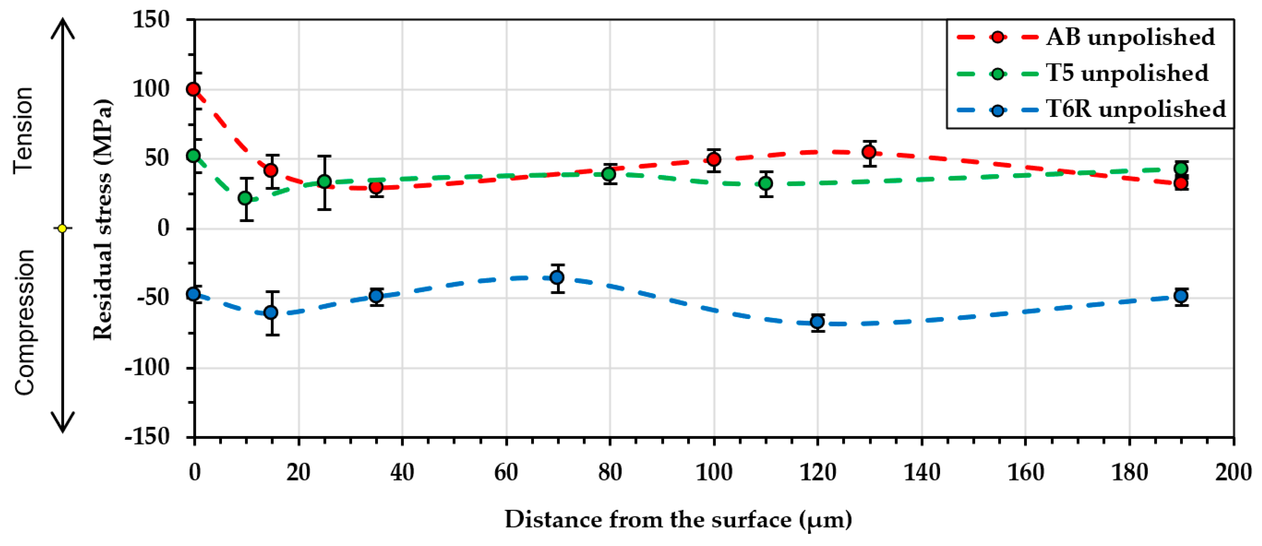
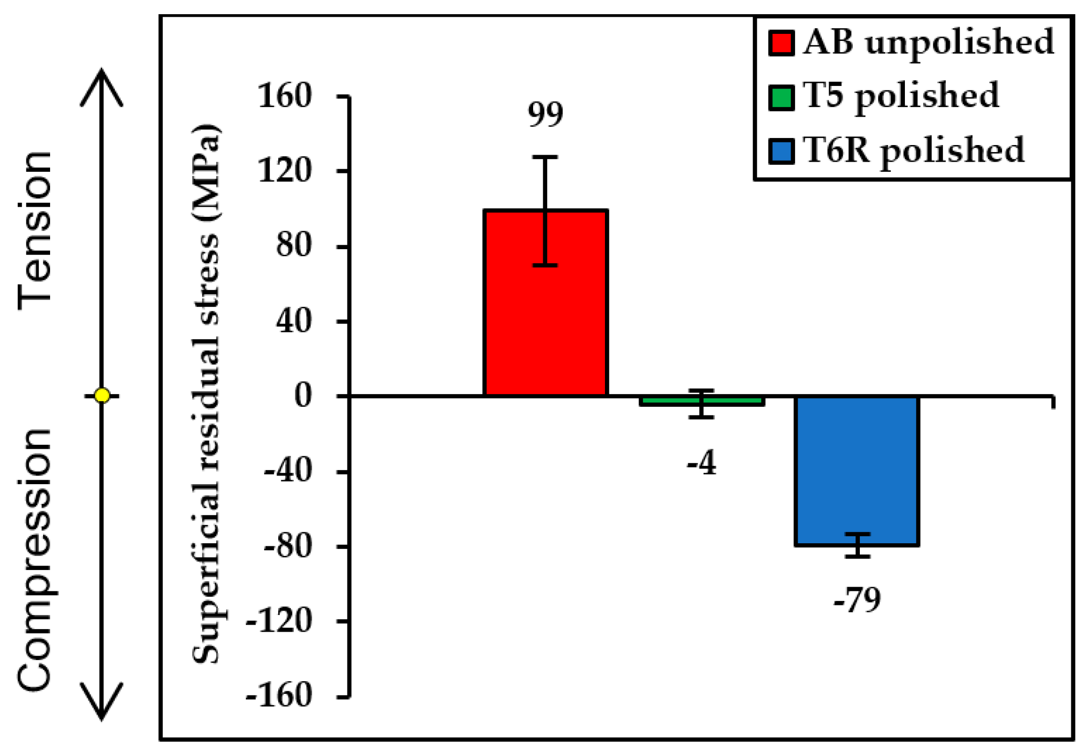
3.1. Residual Stresses Measurements

Figure 3 reports the in-depth σRes profiles in AB, T5, and T6R unpolished specimens, while Figure 4 compares the residual stress σRes evaluated on the surface of AB unpolished specimens and the T5 and T6R polished ones. The AB specimens have a maximum tensile residual stress on the surface equal to 99 ± 29 MPa and a relatively constant in-depth σRes profile up to approximately 200 μm depth, with an average tensile stress of about 50 MPa, comparable to the value reported in [17]. Using a heated platform (150 °C) during printing (30 h) did not relieve the residual stress of the material. Similarly, the low-temperature T5 heat treatment does not significantly relieve the tensile σRes resulting from the L-PBF printing, as visible in Figure 3 from the surface tensile σRes of 52 ± 12 MPa and the in-depth profile comparable to the profile of the AB condition.
The T6R heat treatment determines a completely different residual stress condition. A compressive σRes of −47 ± 16 MPa is measured in the surface position of unpolished specimens, and the in-depth σRes profile appears constant for all the investigated depths, with an average value of approximately −50 MPa (Figure 3).
Figure 4 shows the effects of the surface polishing with emery papers performed on T5 and T6R fatigue specimens. As reported in [16,33,34], it modifies the pre-existing residual stresses introducing compressive stresses for depths up to about 50 μm. Therefore, the polished T5 shows a slight compressive stress (−4 ± 6 MPa), while in the polished T6R, the compressive residual stress increases from −47 ± 16 to −79 ± 6 MPa.
The results of the residual stresses measurements confirm the literature data [14,16,17,35,36,37]: heat treatments, surface polishing, and machining can reduce the residual tensile stresses or even introduce compressive residual stresses in the L-PBF AlSi10Mg alloy, thus improving its cyclic mechanical performances.

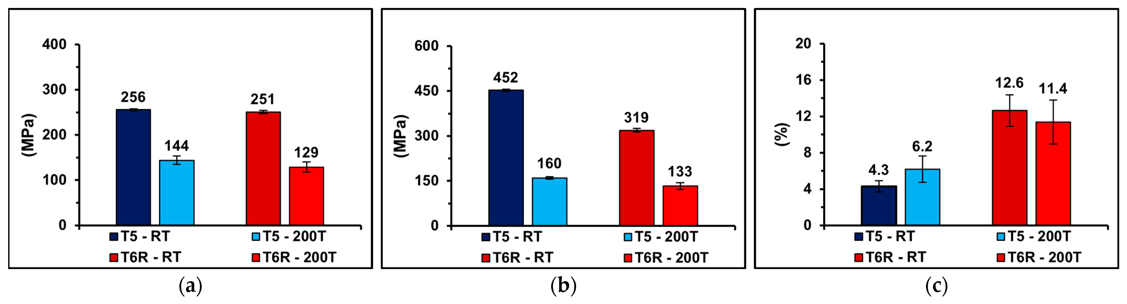
3.2. Microstructural and Mechanical Characterization

The T5 alloy preserves the ultrafine cellular structure of the AB alloy in the melt pool core (MPC), promoting, at the same time, the precipitation of nanosized Si particles from the supersatured α-Al cells (Figure 5c) and the β′′ and β′ strengthening phases (precursors of the Mg2Si equilibrium phase) [19,22]. However, large areas of the microstructure are characterized by an inhomogeneous intercellular eutectic Si network (Figure 5a). In particular, the lower eutectic Si content in the heat-affected zones (HAZs) of the cellular boundaries and the coarse microstructure in the melt pool boundaries (MPBs) (Figure 5b) lead to more straightforward dislocation motion and, therefore, to localized plastic deformation during tensile tests [38].
Under the conditions of maximum thermal exposure, 17 h at 200 °C for run-out specimens, no evidence of thermal degradation, such as the initial dissolution of the eutectic Si network or the formation of primary spheroidal Si particles, appears on the cellular microstructure in the T5 alloy (Figure 6). However, a slight increase in nanosized Si particle size and density within the α-Al cells is evident in Figure 6c, as reported in [29].
The T6R heat treatment forms a homogeneous composite-like microstructure of fine Si particles in the α-Al phase matrix (Figure 7) and fine precipitation of β′′ and β′ strengthening phases, as widely described by [20,37]. However, the high TSHT and long tSHT lead to gas expansion within the bulk material and significant pore growth, around 20% in volume, as reported in a previous study [28]. The specimens observed before the high-temperature test (Figure 7a,c) and after 2 × 10⁶ cycles (about 17 h) at 200 °C (Figure 7b,d) do not show significant differences in Si particle features. In particular, in both conditions, the average area of the Si particles is 0.14 ± 0.02 µm2.
After run-out tests, the T5 hardness decreases from 122 ± 1 HB10 to 110 ± 2 HB10, while the T6R hardness reduces from 94 ± 3 HB10 to 72 ± 2 HB10. As no macroscopic evidence of the microstructural evolution of the T5 and T6R alloys is found (Figure 5, Figure 6 and Figure 7), precipitation hardening is probably the strengthening mechanism most affected by thermal exposure at temperatures up to 200 °C [20,39]. However, decreased solid solution strengthening, lower cohesion between the soft Al and hard Si phases, partial dislocation annihilation, and Al matrix softening may have played a role in the hardness reduction.
As the authors described in [28], the microstructural characteristics of the T5 alloy result in high ultimate tensile strength (UTS) and yield strength (YS) but limited ductility at room temperature (Figure 8). In contrast, the complete microstructural evolution in the T6R alloy led to a different balance between the tensile properties at room temperature. In particular, it led to a lower UTS, a comparable YS, and a significant increase in elongation to failure (ef) compared to the T5-RT (Figure 8).
As described by the authors in [29], at 200 °C, the YS and UTS values decrease similarly (Figure 8): (i) 45 and 50% in YS and (ii) 65 and 60% in UTS for T5-200T and T6R-200T, respectively. The deterioration of the strengthening mechanisms and the thermal softening are the leading causes of the decrease in the strength properties. The ef of the T6R-200T does not increase as expected due to the inhomogeneous and localized plastic deformation of the α-Al matrix and the consequent premature failure of the specimens. However, it is about twice the ef of the T5-200T.
The microstructural changes occurring during the heat treatment and the effect of high temperatures on tensile mechanical properties can help explain the alloy’s different cyclic mechanical responses at room temperature and 200 °C, as summarized in Figure 9.
The room-temperature data show a σfs,50% value equal to 92 ± 15 MPa for the T5-RT and 108 ± 5 MPa for the T6R-RT. The best strength-to-ductility trade-off and the compressive residual stress contribute to higher T6R fatigue strength, as Farkoosh et al. [40] reported for AlSi cast alloys. The inhomogeneous microstructure and lower ductility of the T5 probably constitute a minor obstacle to crack initiation, leading to a lower σfs value and a higher data scattering, despite a higher UTS value than T6R.
The high-temperature fatigue results confirm the well-known effect of thermal exposure on the AlSi alloys [41,42]; in fact, thermal exposure at 200 °C during the fatigue test significantly affects the σfs of the T5-200T and T6R-200T, with results equal to 74 ± 12 MPa and 91 ± 4 MPa, respectively. The higher T6R-200T ductility reduces the material’s defect sensitivity, increasing fatigue strength, as reported in the room temperature data.
As already observed at 200 °C for YS and UTS, comparable percentage reductions of the cyclic mechanical performances, equal to 20% and 15%, characterize the T5-200T and the T6R-200T, respectively. It would explain that for short-term exposure to 200 °C, the decrease in static and cyclic strength properties is mainly due to thermal softening rather than microstructural degradation or excessive overaging of the strengthening precipitates (less than 17 h).

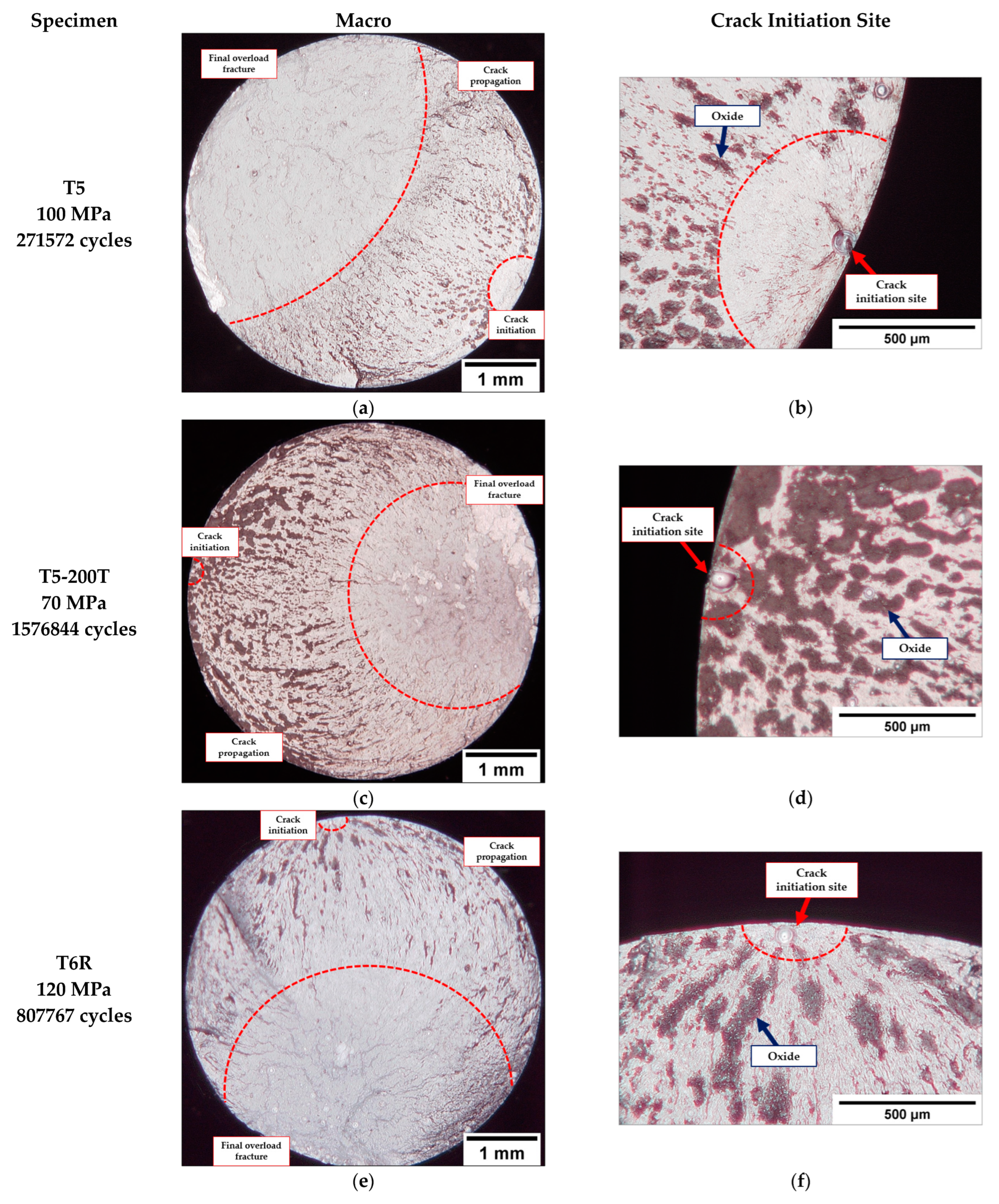
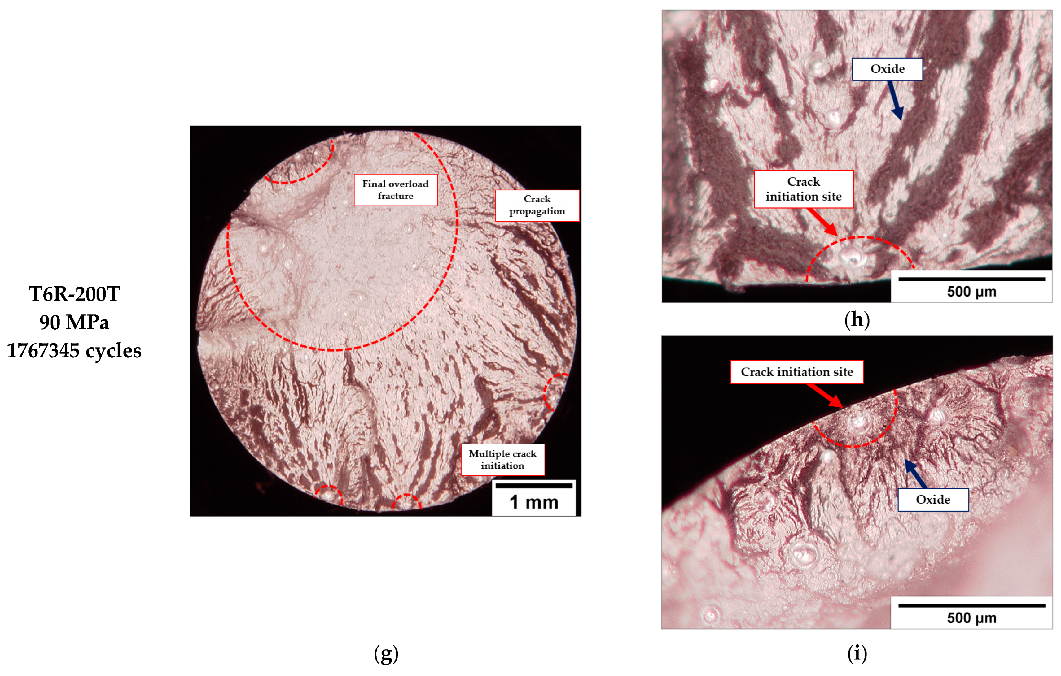
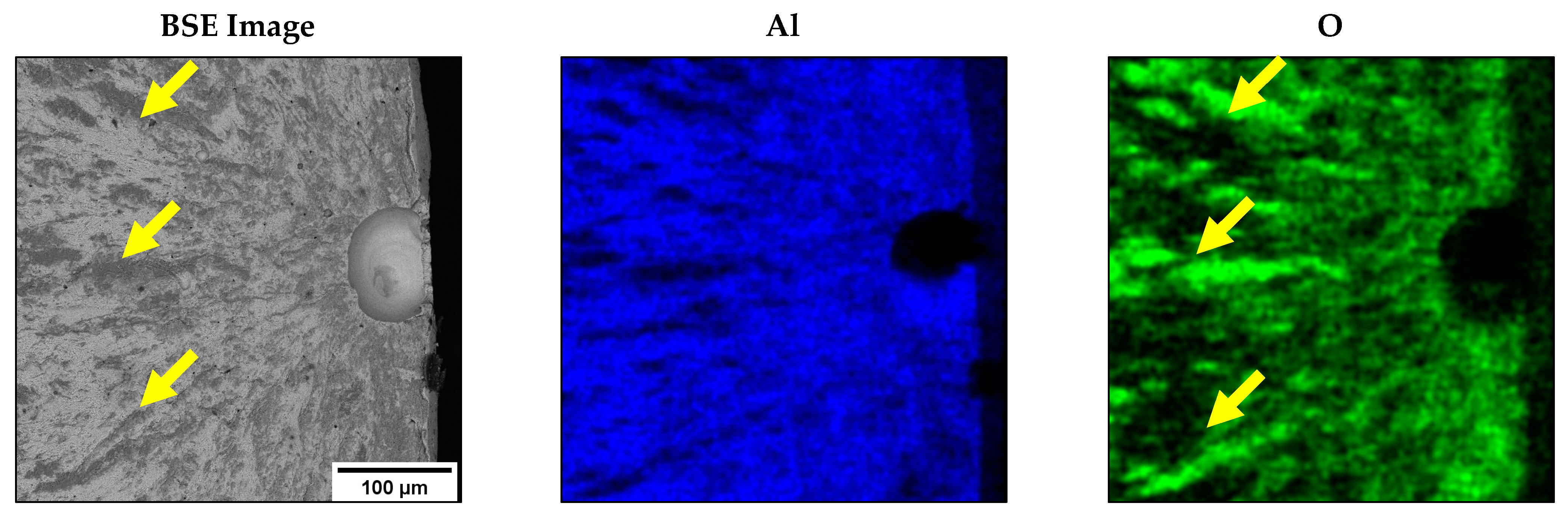
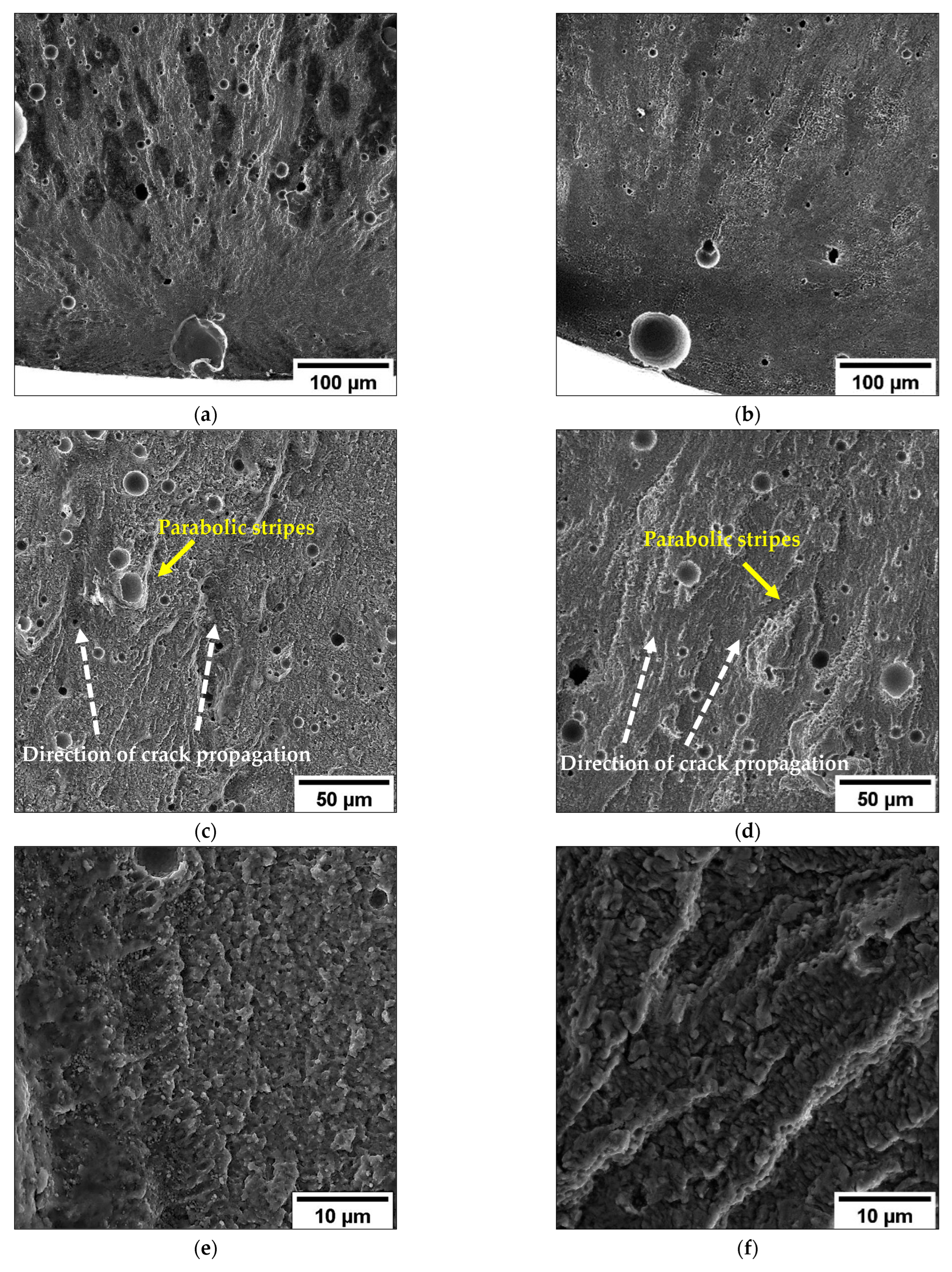
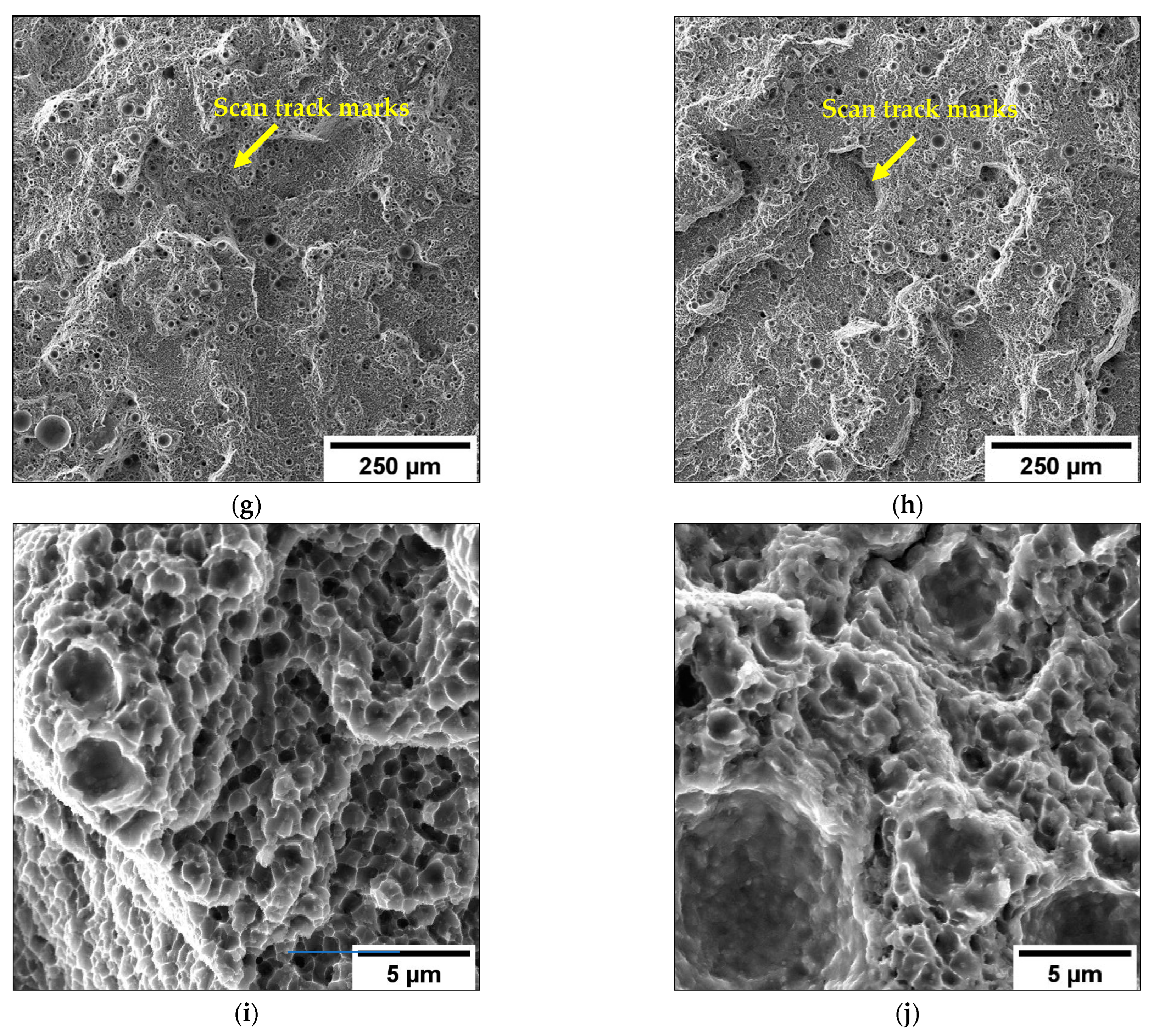
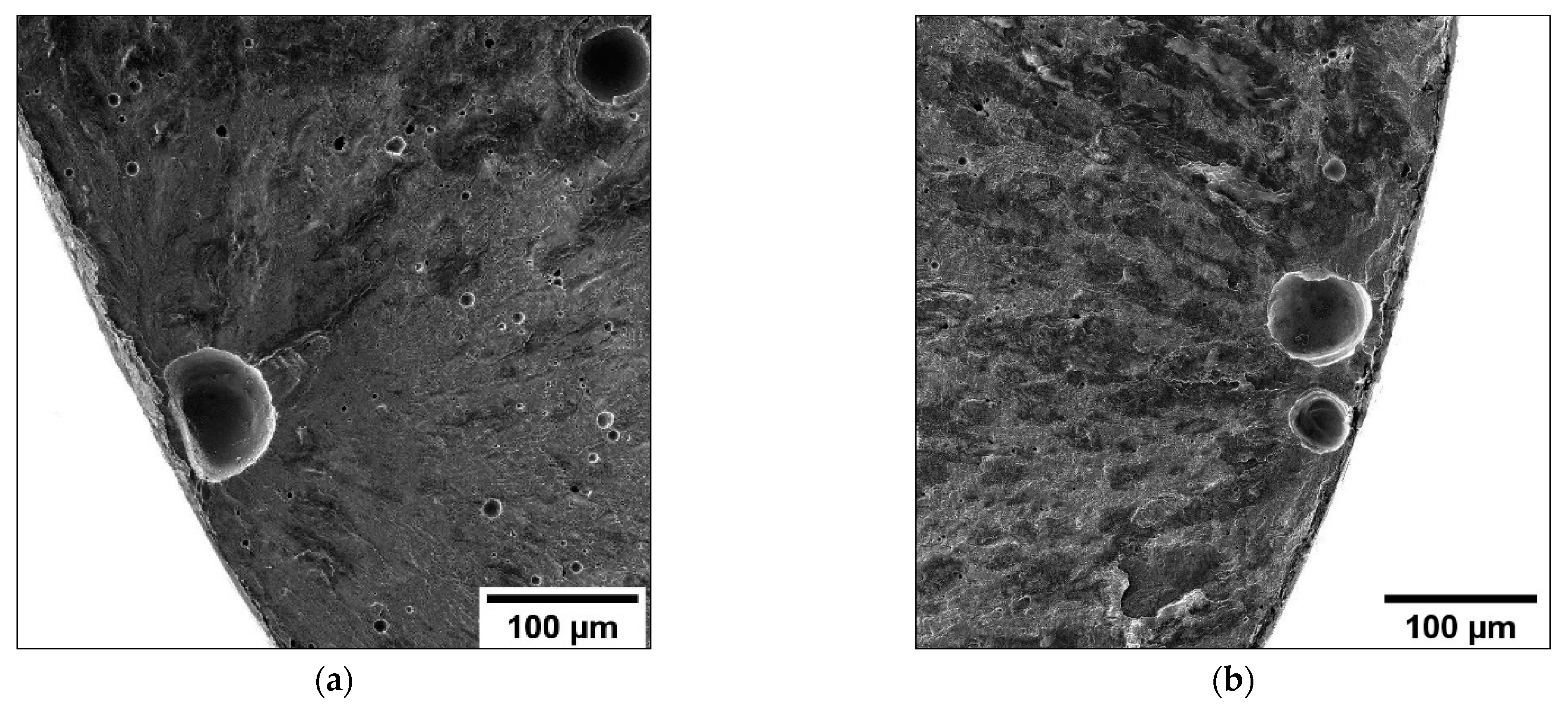
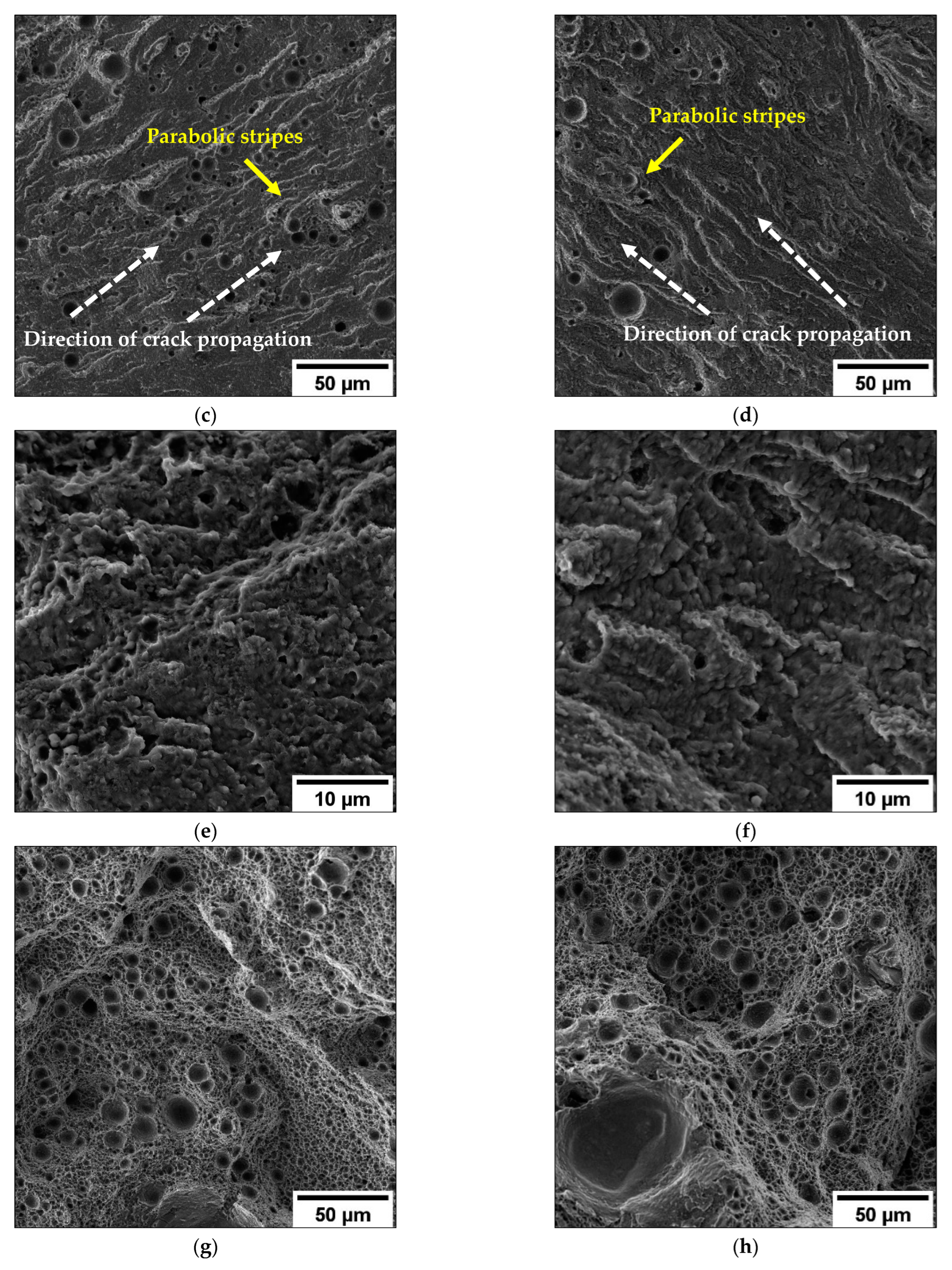
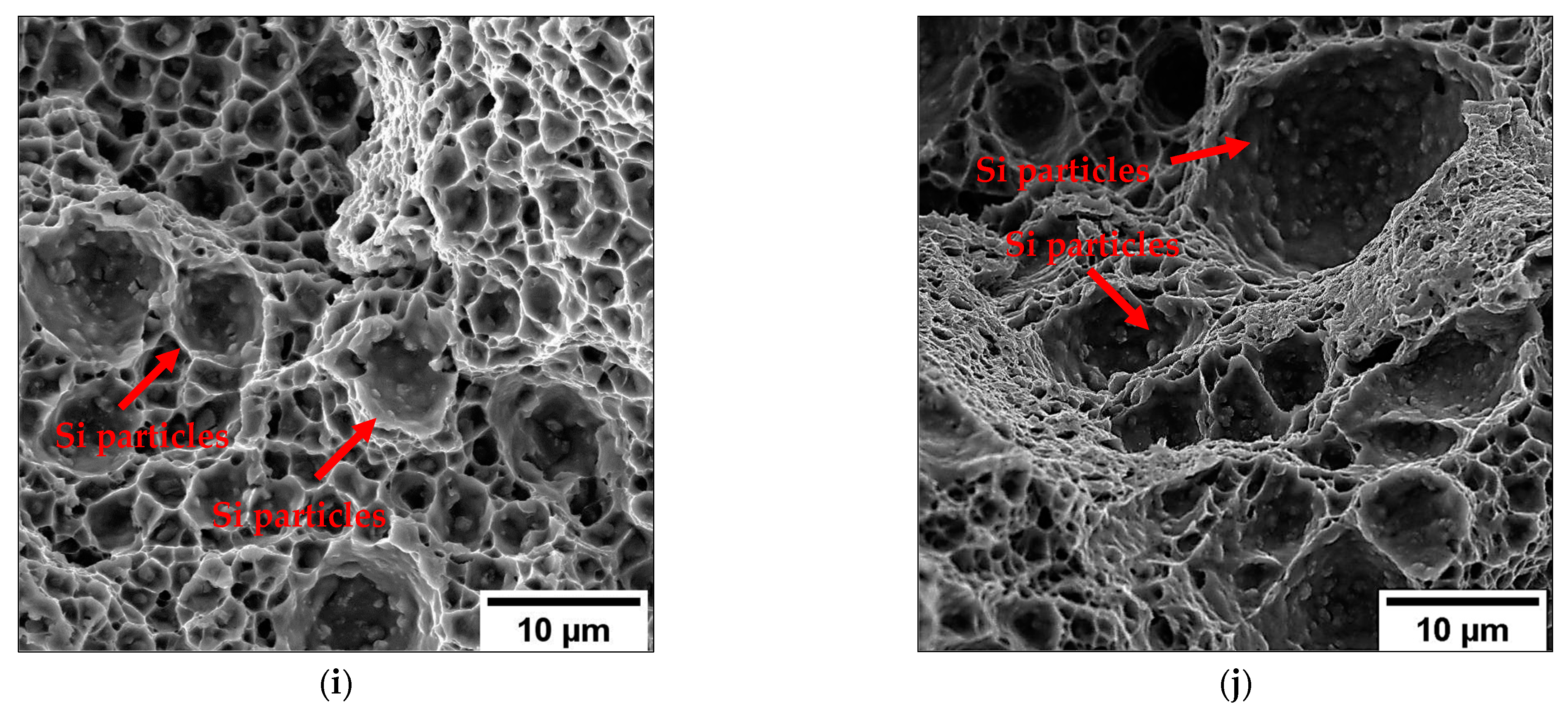
3.3. Fracture Surface Analysis

Low-magnification multi-focus images of the room- and high-temperature fracture surfaces are reported in Figure 10. In all the failed specimens, the fracture develops in three typical stages, namely, (i) crack initiation, (ii) crack propagation, and (iii) final overload fracture. The applied stress amplitude (σa) influences the fracture morphology: higher stresses induce less extensive fatigue crack propagation area and more extensive final overload fracture zones in each tested condition.
No creep phenomena are observed in the specimens tested at 200 °C, as already reported for AlSi cast alloys [43,44]. However, the high surface stress concentration induced by sub-surface defects and the lower material strength due to thermal exposure often promotes multiple crack initiation in T5-200T and T6R-200T. Multiple cracks develop on different planes and connect during the specimen failure (Figure 10g–i).
Large, oxidized zones characterize the fracture propagation zone due to the high Al reactivity, as highlighted by EDS maps (Figure 11). However, the high-temperature fracture surfaces show more extensive oxide regions (Figure 10c,g), which are larger than those observed on the room-temperature fracture surfaces (Figure 10a,e) due to the catalyst effect of the high temperatures on Al oxidation [45].
High-magnification fractography (Figure 12 and Figure 13) confirms that in T5 and T6R tested at room temperature (Figure 12a and Figure 13a) and high temperatures (Figure 12b and Figure 13b), a fracture initiates from the sub-surface spherical voids, such as large gas or keyhole pores, with a Feret diameter between 50 and 100 µm (killer defects), propagating radially through the softer Al phase.
Planar fatigue crack surface, micro-tearing, and fatigue striations (Figure 12c,d and Figure 13c,d) can be observed in the fatigue propagation region [41]. The parabolic stripes around the defects, typical of the tear-fracture morphology (Figure 12e,f and Figure 13e,f), radiate away from the initiation sites and follow the crack growth direction [46]. They are characteristic of stable crack propagation when significant plastic strain accompanies the fatigue fracture propagation [17,35]. At higher magnification, the surfaces display a high density of fatigue striations, which are more evident in specimens tested at high temperatures than at room temperature (Figure 12c,d and Figure 13c,d).
The overload fracture zones exhibit ductile behavior. In particular, the T5-RT (Figure 12g,i) show shallow dimples inside the Si cellular eutectic. The area of the dimples ranges from 0.1 and 20 µm2, and it is comparable to the different cellular microstructural zone: smaller dimples at the MPC and larger dimples at the MPBs and HAZs (Figure 5 and Figure 6). In particular, small tear-ridge facets and dense shear ridges mixed with dimple regions, typical of quasi-brittle fracture, are visible. In addition, it is possible to identify the tearing damage along the scan tracks, which represents the weakest areas in the alloy and, therefore, the preferential fatigue crack path (Figure 12g).
The final failure region of the T5-200T (Figure 12h,j) shows a more pronounced ductile morphology characterized by extensive and deeper dimples compared to the T5-RT (Figure 12g,i). In particular, the softening of the Al matrix, the loss of efficiency of the strengthening mechanisms, and the lower cohesion between the Al matrix/eutectic Si network promote higher plasticity and larger dimple formation at the eutectic Si network/Al matrix interface. In this case, the area of the dimples ranges from 1 and 100 µm2, and it is larger than the cellular eutectic microstructure.
In the T6R alloy, the cellular α-Al cells are not present, and the eutectic Si network evolves into larger Si particles. The final fracture area displays a ductile fracture with relatively deep dimples (Figure 13i) compared to T5 and larger gas pores (Figure 13g) induced by the SHT step. Due to the differences in elastoplastic behavior between the softer Al phase and the Si particles, the Al matrix undergoes extensive local plastic deformation around the Si particles, thus promoting the material detachment and the formation of larger dimples due to the plastic relieving of the Al matrix near the Si particles. Inside the dimples, small silicon particles are visible.
The final fracture area of the T6R-200T displays a ductile fracture (Figure 13h,j) with dimples larger than in the T6R-RT (Figure 13g,i) because the increase in the difference in the elastoplastic behavior between the Al phase and the Si particles leads to a further growth of the plastic relieving of the Al.

4. Discussion

The FEG-SEM analyses show different failure mechanisms between T5 and T6R but do not highlight substantial differences in the failure mechanisms observed at room and high temperatures (Figure 12 and Figure 13). In particular, the fracture surfaces of the high-temperature fatigue specimens and the microstructural analysis (Figure 5, Figure 6 and Figure 7) do not show creep phenomena that could occur at high temperatures. The high frequency of the fatigue tests, the absence of average stress due to the cyclic symmetric fatigue test, and the short exposure time at high temperatures could be the main factors for the absence of creep phenomena, as described for AlSi cast alloys [44,47].
T6R exhibits a superior cyclic mechanical response compared to T5 at room and elevated temperatures. In particular, the high strength of the MPC leads the plastic deformation to concentrate in the HAZs and MPBs in the T5 microstructure, promoting a triaxial stress condition and the consequent formation of microcracks and microvoids at the Al/Si interface due to the strain incompatibility between the Al phase and the eutectic Si, or the crack of the eutectic Si network [48,49]. Therefore, as described in [9], the T5 alloy presents a higher stress-sensitive crack initiation: once the damage starts, the Si network transfers the stress to the Al phase, and the cracks could quickly grow by connecting the voids and fractured zone of the Si network. This phenomenon makes the crack initiation easier due to the limited plastic behavior of the Si-rich phase of the eutectic network. In contrast, the spheroidization of the eutectic Si network and coarsening of the nanosized Si precipitates after T6 heat treatment reduce the localized shear stress at the Al/Si interface and promote higher cohesion between the Si particles/Al matrix. The spheroidal morphology of the Si particles limits crack initiation and propagation. In particular, the integrity of the Si particles compared to the eutectic Si network helps the deformation of the Al matrix, delaying the collapse of the microstructure and specimen failure.
In the T5 alloy, the dislocation density close to the Si network rises with the increase in cycles and leads to microcracks and void formation at the Al cell/eutectic Si network interface, easing the detachment of the softer Al phase of the Si network and the crack nucleation and growth from the sub-superficial killer defects. Instead, the higher ductility and compressive residual stress of the T6R alloy compared to the T5 alloy induces slower fatigue crack initiation [38]. In this way, the T6R heat treatment improves the fatigue strength of the alloy while being characterized by a higher defect volume and a lower UTS than the T5 alloy.
The synergistic effects of increased ductility, microstructural homogenization, and residual stress relieving in T6R increase the material’s capacity to withstand killer defects, delaying crack initiation and limiting the detrimental effect of the increased gas pore volume due to the high TSHT and lower tensile strength. Furthermore, the moderate compressive residual stresses compared to the slight tensile residual stresses persisting in T5 constitute a further significant contribution to the fatigue strength improvement. Therefore, despite the lower UTS, the damage mechanisms characterizing the different microstructures of the alloy promote the higher σfs and lower data scattering in T6R than in T5.
Lastly, it is worth noting that the loss of efficiency in the strengthening mechanisms, particularly thermal softening, causes a reduction in static and cyclic strength [50]. However, high temperatures influence the static mechanical behavior of the T5 and T6R more than their fatigue behavior. While the decrease in UTS at 200 °C is about 60% [29], the σfs is only about 15% for the T5 and T6R alloys. Probably this behavior is a consequence of (i) the leading role of the surface or sub-surface defects as crack initiation in the fatigue behavior even at high temperatures [51]; (ii) the insignificant influence of high temperatures on the size and distribution of the defects (up to 200 °C); (iii) the favorable thermal softening of the Al matrix in opposition to crack nucleation and propagation during cyclic loading.

5. Conclusions

This study investigated the influence of different heat treatments on the cyclic mechanical response of the AlSi10Mg alloy produced by the L-PBF process: T5 (AA at 160 °C for 4 h) and T6R (SHT at 510 °C for 10 min, followed by AA at 160 °C for 6 h). Near-net-shape specimens with the longitudinal axis perpendicular to the building platform and polished gauge section were used. Room- and high-temperature (200 °C) full reversal rotating bending tests were carried out using a staircase method. From the results of the microstructural and fractographic analyses and mechanical tests, the following conclusions can be drawn:
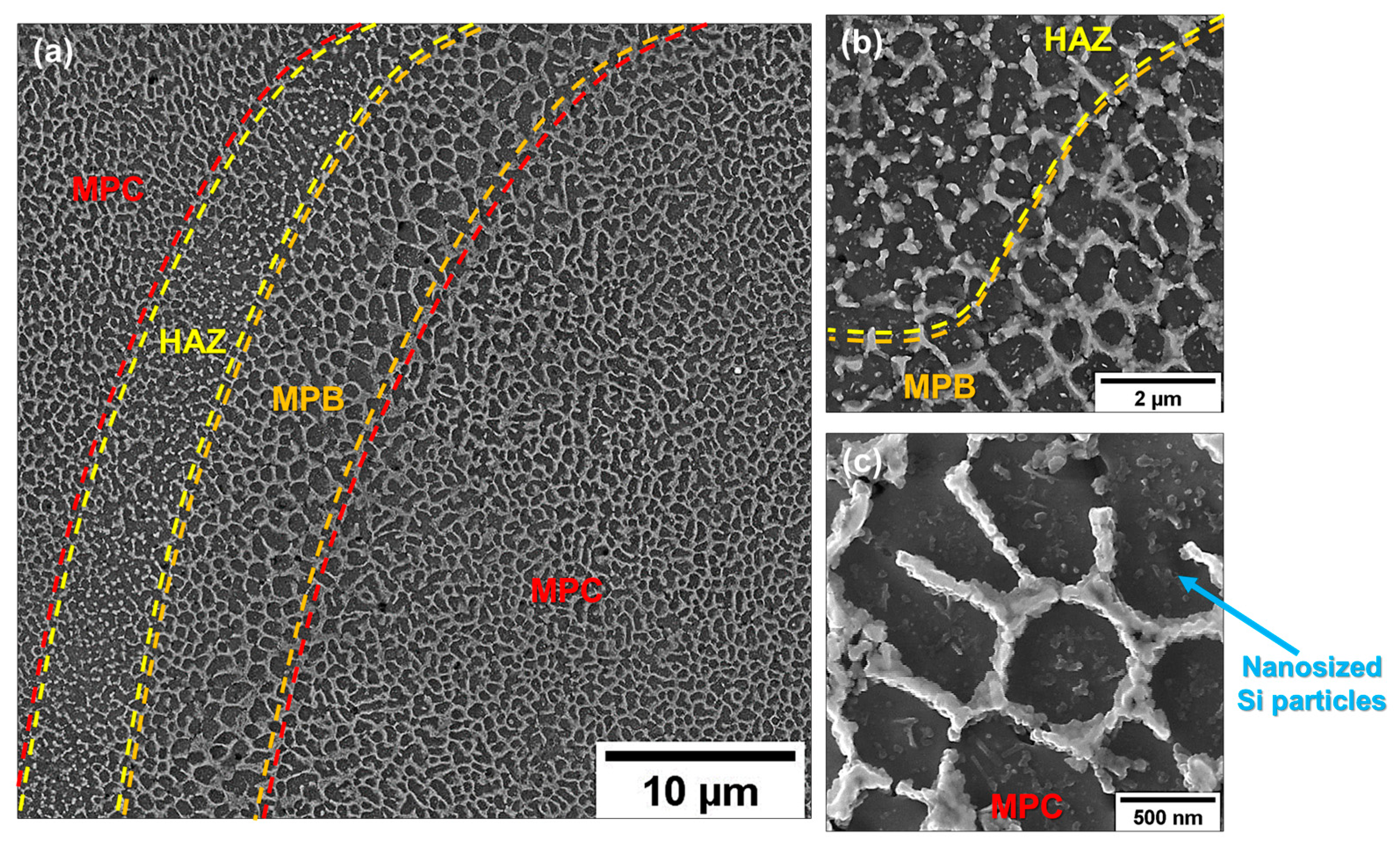
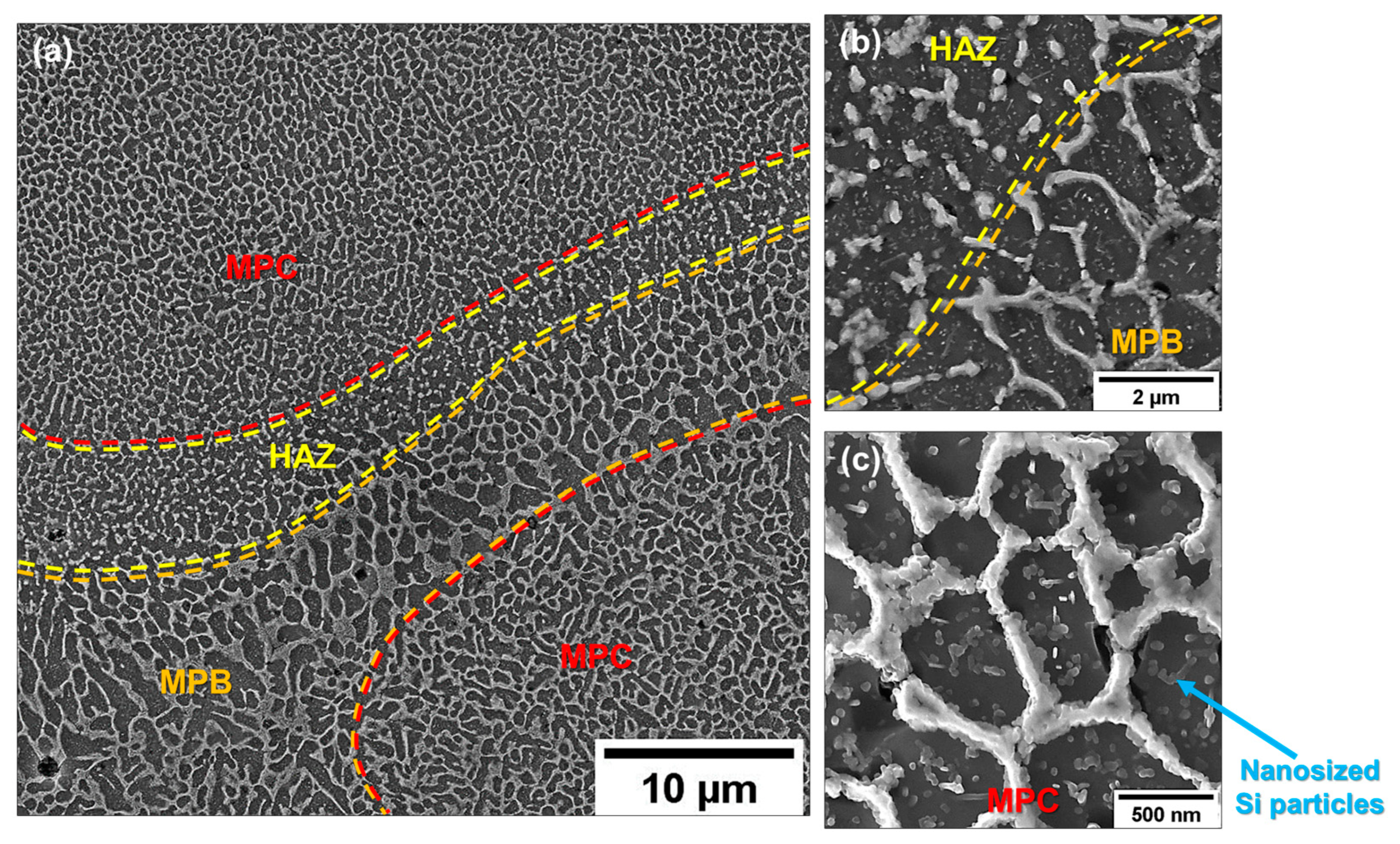
  • The T5 heat treatment has a non-significant effect on the ultrafine cellular structure of the AB alloy but induces a reduction of about 50% of the tensile residual stresses;
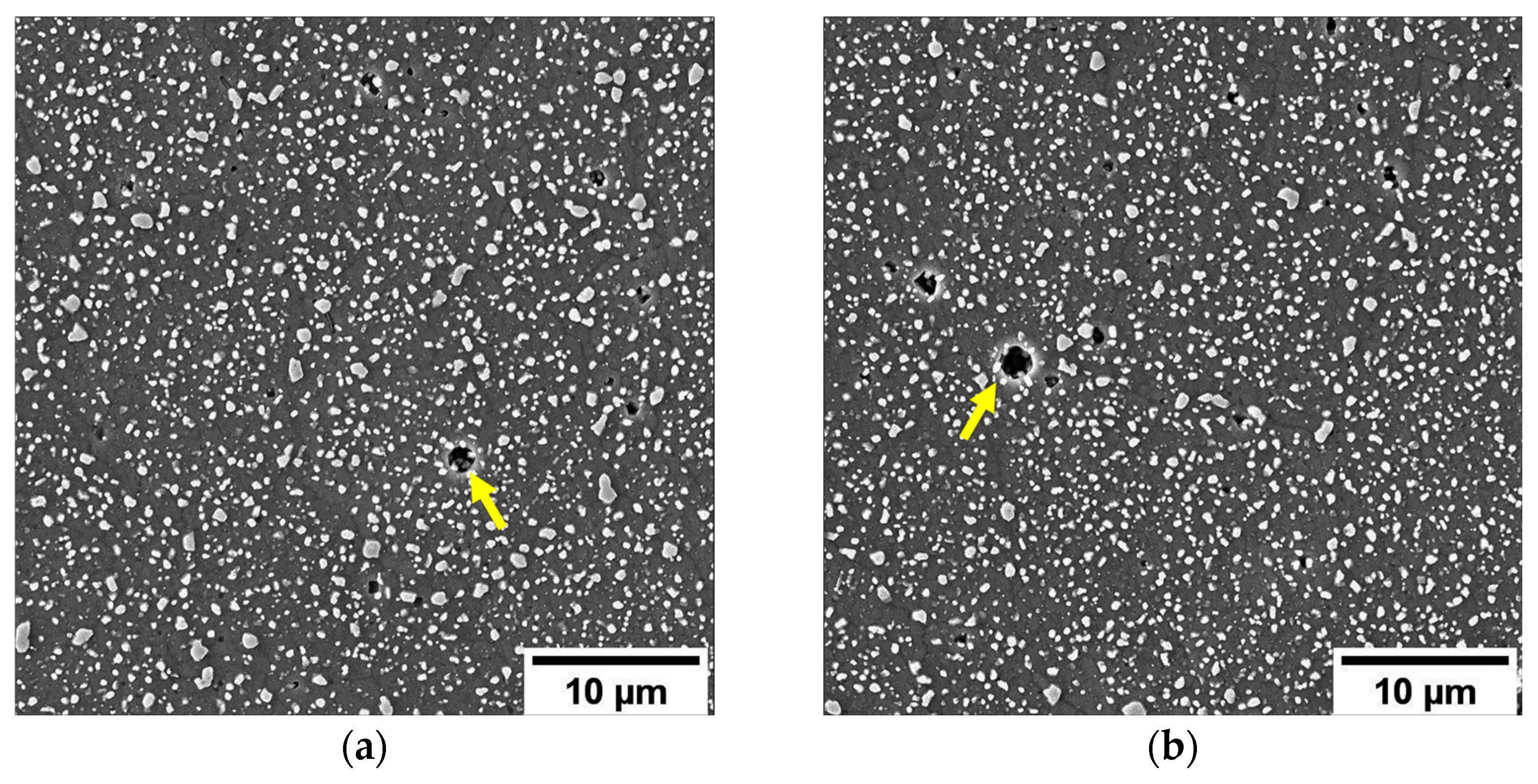
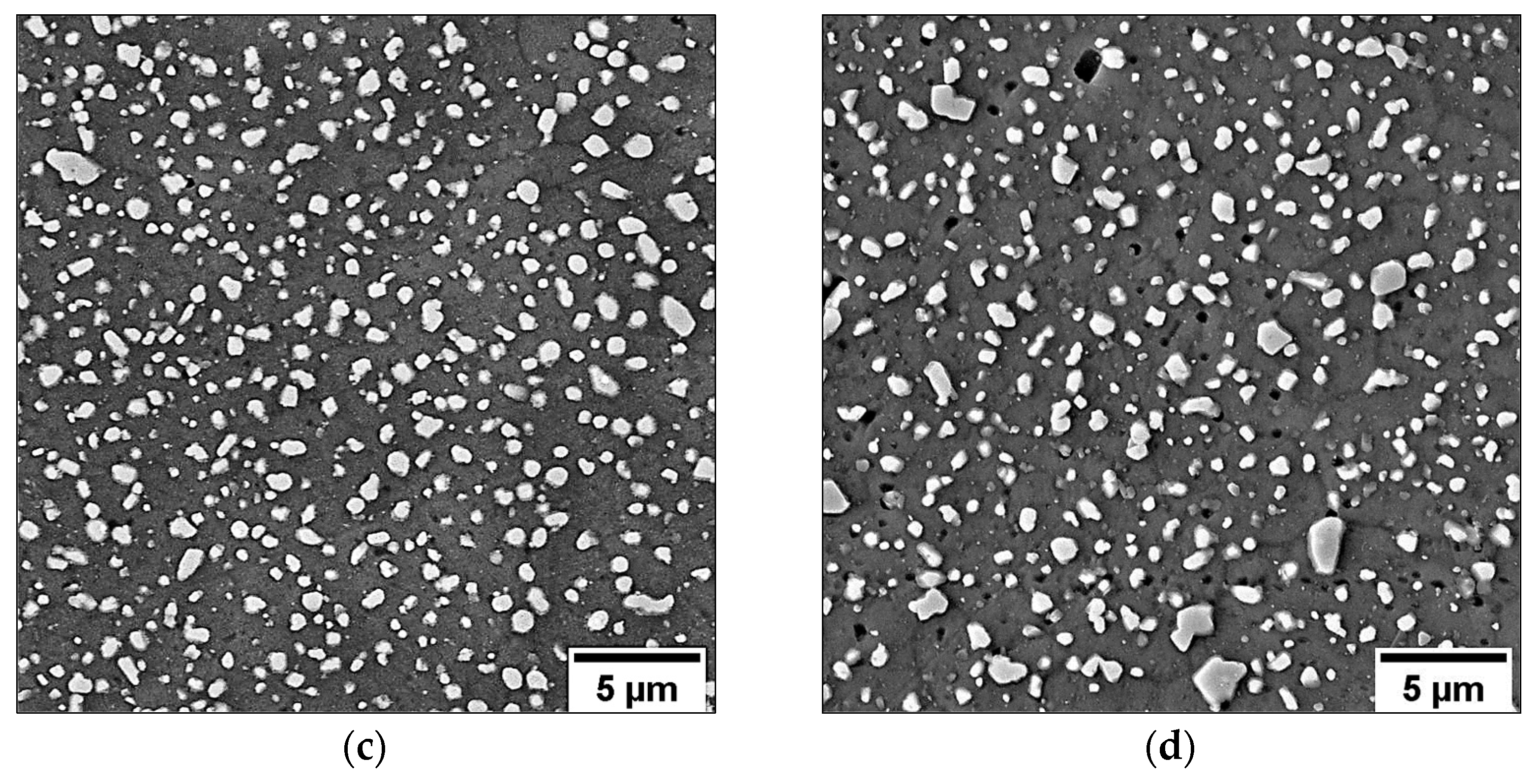
  • The T6R heat treatment induces a composite-like microstructure consisting of Si spheroidal particles embedded into the α-Al matrix and compressive residual stresses;
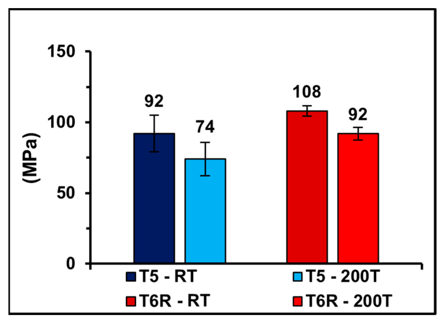
  • The homogeneous microstructure, the residual stress relieving, and the higher ductility–strength balance ensure a better fatigue behavior of the T6R alloy at room (108 ± 4 MPa) and high temperatures (91 ± 4 MPa) compared to the T5 alloy (92 ± 15 MPa and 74 ± 12 MPa, respectively). Microstructural degradation is probably not the main factor influencing fatigue resistance at high temperatures, characterized by a lower decrease compared to the static mechanical properties;
  • Microstructure influences crack initiation. In the T5 alloy, the eutectic Si network is less resistant to crack initiation than the composite-like microstructure of the T6R alloy;
  • The failure mechanisms at room temperature and 200 °C for the specimens subjected to the same heat treatment are comparable. The absence of creep phenomena justifies this result.
In conclusion, the T5 and T6R heat-treated L-PBF AlSi10Mg alloys provide good cyclic mechanical properties at room temperature and up to 200 °C, representing a good solution for producing reliable structural components and fully exploiting L-PBF technology.

Author Contributions

Conceptualization, G.D.E. and A.M.; methodology, G.D.E., A.M. and M.Z.; validation, A.M. and G.D.E.; investigation, G.D.E. and M.Z.; data curation, G.D.E. and A.M.; writing—original draft preparation, G.D.E. and M.Z.; writing—review and editing, G.D.E., A.M. and L.C.; supervision, A.M. and L.C.; project administration, A.M.; funding acquisition, A.M. All authors have read and agreed to the published version of the manuscript.

Funding

Funded by the RIMMEL project, CUP B91F18000370009, POR FESR EMILIA ROMAGNA 2014–2020, Asse 1—Ricerca e Innovazione.

Institutional Review Board Statement

Not applicable.

Informed Consent Statement

Not applicable.

Data Availability Statement

Not applicable.

Conflicts of Interest

The authors declare no conflict of interest.

Nomenclature

σfs,50%Fatigue strength at a 50% probability of failure
σaFatigue stress amplitude
σResResidual stresses
TSHTSolution temperature
tSHTSolution soaking time
T5T5 heat-treated alloy
T6RT6R heat-treated alloy
T5-RTT5 alloy tested at room temperature
T6R-RTT6R alloy tested at room temperature
T5-200TT5 alloy tested at 200 °C
T6R-200TT6R alloy tested at 200 °C

Abbreviations

ABAs-Built
AAArtificial Aging
efElongation to Failure
EDSEnergy Dispersive X-ray Spectroscopy
FEG-SEMField Emission-Gun Scanning Electron Microscopy
GD-OESGlow Discharge Optical Emission Spectroscope
HAZsHeat-affected Zones
L-PBFLaser-based Powder Bed Fusion
MPMelt Pool
MPBsMelt Pool Boundaries
MPCMelt Pool Core
SHTSolution
YSYield Strength
UTSUltimate Tensile Strength

References

  1. Ingarao, G.; Priarone, P.C.; Deng, Y.; Paraskevas, D. Environmental modelling of aluminium based components manufacturing routes: Additive manufacturing versus machining versus forming. J. Clean. Prod. 2018, 176, 261–275. [Google Scholar] [CrossRef]
  2. Zhao, L.; Song, L.; Santos Macías, J.G.; Zhu, Y.; Huang, M.; Simar, A.; Li, Z. Review on the correlation between microstructure and mechanical performance for laser powder bed fusion AlSi10Mg. Addit. Manuf. 2022, 56, 102914. [Google Scholar] [CrossRef]
  3. Olakanmi, E.O.; Cochrane, R.F.; Dalgarno, K.W. A review on selective laser sintering/melting (SLS/SLM) of aluminium alloy powders: Processing, microstructure, and properties. Prog. Mater. Sci. 2015, 74, 401–477. [Google Scholar] [CrossRef]
  4. Kotadia, H.R.; Gibbons, G.; Das, A.; Howes, P.D. A review of Laser Powder Bed Fusion Additive Manufacturing of aluminium alloys: Microstructure and properties. Addit. Manuf. 2021, 46, 102155. [Google Scholar] [CrossRef]
  5. Babu, A.P.; Huang, A.; Birbilis, N. On the heat treatment and mechanical properties of a high solute Al–Zn–Mg alloy processed through laser powder bed fusion process. Mater. Sci. Eng. A 2021, 807, 140857. [Google Scholar] [CrossRef]
  6. Kenevisi, M.S.; Yu, Y.; Lin, F. A review on additive manufacturing of Al–Cu (2xxx) aluminium alloys, processes and defects. Mater. Sci. Technol. 2021, 37, 805–829. [Google Scholar] [CrossRef]
  7. Iturrioz, A.; Gil, E.; Petite, M.M.; Garciandia, F.; Mancisidor, A.M.; San Sebastian, M. Selective laser melting of AlSi10Mg alloy: Influence of heat treatment condition on mechanical properties and microstructure. Weld. World 2018, 62, 885–892. [Google Scholar] [CrossRef]
  8. Li, W.; Li, S.; Liu, J.; Zhang, A.; Zhou, Y.; Wei, Q.; Yan, C.; Shi, Y. Effect of heat treatment on AlSi10Mg alloy fabricated by selective laser melting: Microstructure evolution, mechanical properties and fracture mechanism. Mater. Sci. Eng. A 2016, 663, 116–125. [Google Scholar] [CrossRef]
  9. Zhao, L.; Santos Macías, J.G.; Ding, L.; Idrissi, H.; Simar, A. Damage mechanisms in selective laser melted AlSi10Mg under as built and different post-treatment conditions. Mater. Sci. Eng. A 2019, 764, 138210. [Google Scholar] [CrossRef]
  10. Aboulkhair, N.T.; Maskery, I.; Tuck, C.; Ashcroft, I.; Everitt, N.M. Improving the fatigue behaviour of a selectively laser melted aluminium alloy: Influence of heat treatment and surface quality. Mater. Des. 2016, 104, 174–182. [Google Scholar] [CrossRef]
  11. Kan, W.H.; Nadot, Y.; Foley, M.; Ridosz, L.; Proust, G.; Cairney, J.M. Factors that affect the properties of additively-manufactured AlSi10Mg: Porosity versus microstructure. Addit. Manuf. 2019, 29, 100805. [Google Scholar] [CrossRef]
  12. Tang, M.; Pistorius, P.C. Oxides, porosity and fatigue performance of AlSi10Mg parts produced by selective laser melting. Int. J. Fatigue 2017, 94, 192–201. [Google Scholar] [CrossRef]
  13. Domfang Ngnekou, J.N.; Nadot, Y.; Henaff, G.; Nicolai, J.; Kan, W.H.; Cairney, J.M.; Ridosz, L. Fatigue properties of AlSi10Mg produced by Additive Layer Manufacturing. Int. J. Fatigue 2019, 119, 160–172. [Google Scholar] [CrossRef]
  14. Damon, J.; Dietrich, S.; Vollert, F.; Gibmeier, J.; Schulze, V. Process dependent porosity and the influence of shot peening on porosity morphology regarding selective laser melted AlSi10Mg parts. Addit. Manuf. 2018, 20, 77–89. [Google Scholar] [CrossRef]
  15. Tridello, A.; Fiocchi, J.; Biffi, C.A.; Chiandussi, G.; Rossetto, M.; Tuissi, A.; Paolino, D.S. Effect of microstructure, residual stresses and building orientation on the fatigue response up to 109 cycles of an SLM AlSi10Mg alloy. Int. J. Fatigue 2020, 137, 105659. [Google Scholar] [CrossRef]
  16. Sausto, F.; Tezzele, C.; Beretta, S. Analysis of Fatigue Strength of L-PBF AlSi10Mg with Different Surface Post-Processes: Effect of Residual Stresses. Metals 2022, 12, 898. [Google Scholar] [CrossRef]
  17. Bagherifard, S.; Beretta, N.; Monti, S.; Riccio, M.; Bandini, M.; Guagliano, M. On the fatigue strength enhancement of additive manufactured AlSi10Mg parts by mechanical and thermal post-processing. Mater. Des. 2018, 145, 28–41. [Google Scholar] [CrossRef]
  18. Zhang, C.; Zhu, H.; Liao, H.; Cheng, Y.; Hu, Z.; Zeng, X. Effect of heat treatments on fatigue property of selective laser melting AlSi10Mg. Int. J. Fatigue 2018, 116, 513–522. [Google Scholar] [CrossRef]
  19. Alghamdi, F.; Song, X.; Hadadzadeh, A.; Shalchi-Amirkhiz, B.; Mohammadi, M.; Haghshenas, M. Post heat treatment of additive manufactured AlSi10Mg: On silicon morphology, texture and small-scale properties. Mater. Sci. Eng. A 2020, 783, 139296. [Google Scholar] [CrossRef]
  20. Fite, J.; Prameela, S.E.; Slotwinski, J.A.; Weihs, T.P. Evolution of the microstructure and mechanical properties of additively manufactured AlSi10Mg during room temperature holds and low temperature aging. Addit. Manuf. 2020, 36, 101429. [Google Scholar] [CrossRef]
  21. Lattanzi, L.; Merlin, M.; Fortini, A.; Morri, A.; Garagnani, G.L. Effect of Thermal Exposure Simulating Vapor Deposition on the Impact Behavior of Additively Manufactured AlSi10Mg Alloy. J. Mater. Eng. Perform. 2022, 31, 2859–2869. [Google Scholar] [CrossRef]
  22. Casati, R.; Hamidi, M.N.; Coduri, M.; Tirelli, V.; Vedani, M. Effects of Platform Pre-Heating and Thermal-Treatment Strategies on Properties of AlSi10Mg Alloy Processed by Selective Laser Melting. Metals 2018, 8, 954. [Google Scholar] [CrossRef] [Green Version]
  23. Girelli, L.; Tocci, M.; Gelfi, M.; Pola, A. Study of heat treatment parameters for additively manufactured AlSi10Mg in comparison with corresponding cast alloy. Mater. Sci. Eng. A 2019, 739, 317–328. [Google Scholar] [CrossRef]
  24. Brandl, E.; Heckenberger, U.; Holzinger, V.; Buchbinder, D. Additive manufactured AlSi10Mg samples using Selective Laser Melting (SLM): Microstructure, high cycle fatigue, and fracture behavior. Mater. Des. 2012, 34, 159–169. [Google Scholar] [CrossRef]
  25. Konecna, R.; Nicoletto, G.; Kunz, L.; Riva, E. The Role of Elevated Temperature Exposure on Structural Evolution and Fatigue Strength of Eutectic AlSi12 Alloys. Int. J. Fatigue 2015, 83, 24–35. [Google Scholar] [CrossRef]
  26. Czerwinski, F. Thermal Stability of Aluminum Alloys. Materials 2020, 13, 3441. [Google Scholar] [CrossRef]
  27. Lehmhus, D.; Rahn, T.; Struss, A.; Gromzig, P.; Wischeropp, T.; Becker, H. High-Temperature Mechanical Properties of Stress-Relieved AlSi10Mg Produced via Laser Powder Bed Fusion Additive Manufacturing. Materials 2022, 15, 7386. [Google Scholar] [CrossRef]
  28. Di Egidio, G.; Ceschini, L.; Morri, A.; Martini, C.; Merlin, M. A Novel T6 Rapid Heat Treatment for AlSi10Mg Alloy Produced by Laser-Based Powder Bed Fusion: Comparison with T5 and Conventional T6 Heat Treatments. Metall. Mater. Trans. B 2022, 53, 284–303. [Google Scholar] [CrossRef]
  29. Di Egidio, G.; Morri, A.; Ceschini, L. Evaluation of High-temperature tensile properties of heat-treated AlSi10Mg alloy produced by Laser-Based Powder Bed Fusion. In Proceedings of the 31st International Conference on Metallurgy and Materials, Orea Congress Hotel Brno, Brno-střed, Czech Republic, 18–19 May 2022; pp. 580–586. [Google Scholar]
  30. Moses, J.P.; Liu, Q.; Best, J.P.; Li, X.; Kruzic, J.J.; Ramamurty, U.; Gludovatz, B. Fracture resistance of AlSi10Mg fabricated by laser powder bed fusion. Acta Mater. 2021, 211, 116869. [Google Scholar]
  31. Jian, Z.; Piao, Z.Y.; Liu, S.Y.; Su, S.W.; Deng, L.J. Investigation of wear behavior of graphite coating on aluminum piston skirt of automobile engine. Eng. Fail. Anal. 2019, 97, 408–415. [Google Scholar] [CrossRef]
  32. Teng, D.; Wang, J.; Li, C.; Sa, X. Investigation of Friction and Wear Behavior of Cast Aluminum Alloy Piston Skirt with Graphite Coating Using a Designed Piston Skirt Test Apparatus. Materials 2022, 15, 4010. [Google Scholar] [CrossRef]
  33. Shimatani, Y.; Shiozawa, K.; Nakada, T.; Yoshimoto, T.; Lu, L. The Effect of the Residual Stresses Generated by Surface Finishing Methods on the very High Cycle Fatigue Behavior of Matrix HSS. Int. J. Fatigue 2011, 33, 122–131. [Google Scholar] [CrossRef]
  34. Ceschini, L.; Morri, A.; Morri, A.; Messieri, S. Replacement of Nitrided 33CrMoV Steel with ESR Hot Work Tool Steels for Motorsport Applications: Microstructural and Fatigue Characterization. J. Mater. Eng. Perform. 2018, 27, 3920–3931. [Google Scholar] [CrossRef]
  35. Mower, T.M.; Long, M.J. Mechanical behavior of additive manufactured, powder-bed laser-fused materials. Mater. Sci. Eng. A 2016, 651, 198–213. [Google Scholar] [CrossRef]
  36. Fiocchi, J.; Biffi, C.A.; Colombo, C.; Vergani, L.M.; Tuissi, A. Ad Hoc Heat Treatments for Selective Laser Melted Alsi10mg Alloy Aimed at Stress-Relieving and Enhancing Mechanical Performances. JOM 2020, 72, 1118–1127. [Google Scholar] [CrossRef]
  37. Tonelli, L.; Liverani, E.; Morri, A.; Ceschini, L. Role of Direct Aging and Solution Treatment on Hardness, Microstructure and Residual Stress of the A357 (AlSi7Mg0.6) Alloy Produced by Powder Bed Fusion. Metall. Mater. Trans. B 2021, 52, 2484–2496. [Google Scholar] [CrossRef]
  38. Di Giovanni, M.T.; Oliveira de Menezes, J.T.; Bolelli, G.; Cerri, E.; Castrodeza, E.M. Fatigue crack growth behavior of a selective laser melted AlSi10Mg. Eng. Fract. Mech. 2019, 217, 106564. [Google Scholar] [CrossRef]
  39. Fousová, M.; Dvorský, D.; Michalcová, A.; Vojtěch, D. Changes in the microstructure and mechanical properties of additively manufactured AlSi10Mg alloy after exposure to elevated temperatures. Mater. Charact. 2018, 137, 119–126. [Google Scholar] [CrossRef]
  40. Farkoosh, A.R.; Pekguleryuz, M. Enhanced mechanical properties of an Al–Si–Cu–Mg alloy at 300 °C: Effects of Mg and the Q-precipitate phase. Mater. Sci. Eng. A 2015, 621, 277–286. [Google Scholar] [CrossRef]
  41. Ceschini, L.; Morri, A.; Toschi, S.; Seifeddine, S. Room and high temperature fatigue behaviour of the A354 and C355 (Al–Si–Cu–Mg) alloys: Role of microstructure and heat treatment. Mater. Sci. Eng. A 2016, 653, 129–138. [Google Scholar] [CrossRef]
  42. Tocci, M.; Donnini, E.; Angella, G.; Gariboldi, E.; Pola, A. Tensile Properties of a Cast Al-Si-Mg Alloy with Reduced Si Content and Cr Addition at High Temperature. J. Mater. Eng. Perform. 2019, 28, 7097–7108. [Google Scholar] [CrossRef]
  43. Morri, A.; Ceschini, L.; Messieri, S.; Cerri, E.; Toschi, S. Mo Addition to the A354 (Al–Si–Cu–Mg) Casting Alloy: Effects on Microstructure and Mechanical Properties at Room and High Temperature. Metals 2018, 8, 393. [Google Scholar] [CrossRef] [Green Version]
  44. Ceschini, L.; Morri, A.; Morri, A.; Toschi, S.; Johansson, S.; Seifeddine, S. Effect of Microstructure and overaging on the Tensile Behavior at Room and Elevated Temperature of C355-T6 Cast Aluminum Alloy. Mater. Des. 2015, 83, 626–634. [Google Scholar] [CrossRef]
  45. Biffi, C.A.; Bassani, P.; Fiocchi, J.; Giuranno, D.; Novakovic, R.; Tuissi, A.; Ricci, E. Investigation of high temperature behavior of AlSi10Mg produced by selective laser melting. Mater. Chem. Phys. 2021, 259, 123975. [Google Scholar] [CrossRef]
  46. Xu, Z.W.; Wang, Q.; Wang, X.S.; Tan, C.H.; Guo, M.H.; Gao, P.B. High cycle fatigue performance of AlSi10mg alloy produced by selective laser melting. Mech. Mater. 2020, 148, 103499. [Google Scholar] [CrossRef]
  47. Dai, P.; Luo, X.; Yang, Y.; Kou, Z.; Huang, B.; Zang, J.; Ru, J. High temperature tensile properties, fracture behaviors and nanoscale precipitate variation of an Al–Zn–Mg–Cu alloy. Prog. Nat. Acad. Sci. USA 2020, 30, 63–73. [Google Scholar] [CrossRef]
  48. Kim, D.K.; Hwang, J.H.; Kim, E.Y.; Heo, Y.U.; Woo, W.; Choi, S.H. Evaluation of the stress-strain relationship of constituent phases in AlSi10Mg alloy produced by selective laser melting using crystal plasticity FEM. J. Alloys Compd. 2017, 714, 687–697. [Google Scholar] [CrossRef]
  49. Park, T.H.; Baek, M.S.; Hyer, H.; Sohn, Y.; Lee, K.A. Effect of direct aging on the microstructure and tensile properties of AlSi10Mg alloy manufactured by selective laser melting process. Mater. Charact. 2021, 176, 111113. [Google Scholar] [CrossRef]
  50. Delahaye, J.; Tchuindjang, J.T.; Lecomte-Beckers, J.; Rigo, O.; Habraken, A.M.; Mertens, A. Influence of Si precipitates on fracture mechanisms of AlSi10Mg parts processed by Selective Laser Melting. Acta Mater. 2019, 175, 160–170. [Google Scholar] [CrossRef]
  51. Romano, S.; Brückner-Foit, A.; Brandão, A.; Gumpinger, J.; Ghidini, T.; Beretta, S. Fatigue properties of AlSi10Mg obtained by additive manufacturing: Defect-based modelling and prediction of fatigue strength. Eng. Fract. Mech. 2018, 187, 165–189. [Google Scholar] [CrossRef]
Figure 1. Printed specimens used in the experimental campaign: printing direction (a) (adapted from [16]); scan strategy (b).
Metals 13 00263 g001
Figure 2. Rotating bending specimen geometry (dimensions in mm), adapted from [16]. Gauge length surface (highlighted by the red box in (a)) before (b) and after (c) polishing.
Metals 13 00263 g002
Figure 3. Distribution of residual stresses as a function of the distance from the unpolished surface of the AB, T5, and T6R.
Metals 13 00263 g003
Figure 4. Comparison of residual stress σRes measured on the AB unpolished surface and T5 and T6R polished surfaces.
Metals 13 00263 g004
Figure 5. T5 microstructure before high-temperature tests observed on the transversal section of fatigue specimens. Intersection area between adjacent scan tracks (a). Detail of the MPB and HAZ on border area (b) and MPC (c).
Metals 13 00263 g005
Figure 6. T5 microstructure after 2 × 10⁶ cycles (about 17 h) at 200 °C observed on the transversal section of fatigue specimens. Intersection area between adjacent scan tracks (a). Detail of the MPB and HAZ border area (b) and MPC (c).
Metals 13 00263 g006
Figure 7. T6R microstructure observed on the transversal section of fatigue specimens: before high-temperature tests (a,c) and after 2 × 10⁶ cycles (about 17 h) at 200 °C (b,d). Yellow arrows in (a) and (b) highlight gas pores.
Metals 13 00263 g007aMetals 13 00263 g007b
Figure 8. Tensile properties (YS (a), UTS (b), and ef (c)) of the T5 and T6R alloys tested at room temperature (T5-RT and T6R-RT) (i) and 200 °C (T5-200T and T6R-200T) (ii). T-bars represent the standard deviation of YS, UTS, and ef. More details about tensile characterization are available in [28,29].
Metals 13 00263 g008
Figure 9. Fatigue strength (σfs,50%) of the T5 and T6R alloys tested at room temperature (T5-RT and T6R-RT) (i) and high temperatures (T5-200T and T6R-200T) (ii). T-bars represent the standard deviation of fatigue strength.
Metals 13 00263 g009
Figure 10. Low magnification multi-focus images for T5-RT (a,b), T5-200T (c,d), T6R-RT (e,f), and T6R-200T (gi). Fracture surface regions of interest: (i) crack initiation, (ii) crack propagation, and (iii) final overload fracture.
Metals 13 00263 g010aMetals 13 00263 g010b
Figure 11. BSE image of the crack initiation zone of the T6R alloy. EDS elemental maps of Al (blue) and O (green). The yellow arrows in the BSE image and the O maps highlight the correspondence between dark (BSE image) and green (O map) areas in the propagation region.
Metals 13 00263 g011
Figure 12. SE image of T5-RT (a,c,e,g,i) and T5-200T (b,d,f,h,j) specimens. Killer defect (a,b); crack propagation region (c,d); micro-tearing in the fatigue propagation region (e,f); final overload fracture (g,h); dimple voids (i,j). Yellow arrows indicate parabolic stripes close to the defects in the fatigue crack propagation regions and scan track marks in the overload fracture zone. Dotted white arrows indicate the direction of crack propagation.
Metals 13 00263 g012aMetals 13 00263 g012b
Figure 13. SE image of the T6R-RT (a,c,e,g,i) and T6R-200T (b,d,f,h,j) specimens. Killer defect (a,b); crack propagation (c,d); micro-tearing in the fatigue propagation region (e,f); final overload fracture (g,h); dimple voids (i,j). Red arrows show the Si particles inside large dimples.
Metals 13 00263 g013aMetals 13 00263 g013bMetals 13 00263 g013c
Table 1. Chemical compositions (wt%) include rod specimens (i), evaluated using GD-OES, and nominal composition of the AlSi10Mg alloy (ii), according to EN AC-43000.
Element (wt%)AlSiMgFeCuMnNiPbSnTiZn
SpecimensBal.9.66 ± 0.100.28 ± 0.020.12 ± 0.02-0.006 ± 0.001-0.008 ± 0.0020.025 ± 0.0100.017 0.0030.042 ± 0.009
EN AC-43000Bal.9–110.20–0.45<0.55<0.05<0.45<0.05<0.05<0.05<0.15<0.10
Table 2. L-PBF AlSi10Mg alloy heat treatment conditions.
ConditionHeat TreatmentDesignation of Specimens Tested at Different Temperatures
Room Temperature (25 °C)High Temperature (200 °C)
T5AA at 160 °C for 4 h in air,
air cooling
T5-RTT5-200T
T6RSHT at 510 °C for 10 min in air,
water quenching at room temperature,
AA at 160 °C for 6 h in air,
air cooling
T6R-RTT6R-200T
Disclaimer/Publisher’s Note: The statements, opinions and data contained in all publications are solely those of the individual author(s) and contributor(s) and not of MDPI and/or the editor(s). MDPI and/or the editor(s) disclaim responsibility for any injury to people or property resulting from any ideas, methods, instructions or products referred to in the content.

