Article

Metallurgical Failure Analysis of Closed Water Circuit Containing Molybdate-Based Inhibitor

by
Andrea Casaroli
1,
Marco Virginio Boniardi
1,
Barbara Rivolta
1,*,
Riccardo Gerosa
1 and
Francesco Iacoviello
2
1
Dipartimento di Meccanica, Politecnico di Milano, 20156 Milano, Italy
2
Dipartimento di Ingegneria Civile e Meccanica, Università Degli Studi di Cassino e del Lazio Meridionale, 03043 Cassino, Italy
*
Author to whom correspondence should be addressed.
Metals 2023, 13(4), 723; https://doi.org/10.3390/met13040723
Submission received: 23 February 2023 / Revised: 31 March 2023 / Accepted: 3 April 2023 / Published: 6 April 2023
(This article belongs to the Special Issue Feature Papers in Structural Integrity of Metals)

Abstract

:
In this work, two industrial heating/cooling circuits are compared. One of the two systems failed in a short time showing severe corrosion damage and a through thickness crack close to one of the welds. The main difference between the circuits is the presence of a sodium molybdate-based corrosion inhibitor in the damaged one. The addition of these substances is very frequent in such applications, and they generally work very well in preventing serious corrosion attacks. Nevertheless, the technical literature reports other cases in which systems working with fluids containing such inhibitors failed prematurely. The authors performed a failure analysis of the damaged circuit focusing their attention on the regions where fluid leaks were observed because of through thickness cracks. This damage was located close to the pipe–flange weld. These zones were investigated by visual examination, radiographic and scanning electron microscope (SEM) analyses, metallographic observations by light optical microscope (LOM), Vickers micro-hardness tests and optical emission spectroscopy (OES) chemical analysis. The failure was related to the presence of severe pitting and crevice corrosion in the welded areas with the final activation of a further critical corrosion mechanism, i.e., stress corrosion cracking (SCC). In order to explain the shorter working life of the failed system, a physical model of the corrosion mechanisms acting on the two circuits was proposed.

1. Introduction

The heating/cooling systems of large industrial plants usually employ water-glycol (ethylenic or poli-propylenic) solutions that flow in carbon steel pipes [1,2,3]. Aiming to preventing the pipes’ corrosion, sodium molybdate-based inhibitors are often added to the water-glycol solution [4], even if other chemicals can be used, such as tolyltriazole (TTA) or phosphonates [5,6]. Molybdate-based inhibitors are largely diffused since they also work very well when a significant amount of oxygen is present in water. These substances are very effective anodic inhibitors, even if their efficiency can be significantly reduced in specific service conditions [7]. The lack of oxidizing characteristics allows its mixing with a large number of organic compounds, promoting inhibition synergism. A low amount of second group metals is required in the solution in order to maximize the inhibitor’s efficacy. A molybdate-based inhibitor is often used to control microbiological growth because it is not a nutrient for microbes. It is compatible with the biocides commonly used in closed systems with ethylene and propylene glycols. In order to optimize its use, the pH value must be controlled periodically, and it should always be lower than 9 [8].
In the present work, the root causes of the localized corrosion (pitting, crevice and stress corrosion cracking) that occurred on welded joints of EN P235TR2 steel grade pipes [9] and EN P245GH steel grade flanges [10] are investigated and discussed. These components were installed in one of the two cooling circuits in a co-generation plant. The circuits were designed with the same geometrical characteristics and the same materials. The working temperature was kept between 55 °C and 90 °C, and the pressure was kept between 3 barg (gauge pressure) and 7 barg (gauge pressure). One important difference shall be remarked: a water-ethylenic glycol solution was used in Circuit n.1, whereas a sodium molybdate inhibitor was added to the same solution in Circuit n.2. According to the producer specifications, the inhibitor content was higher than 160 ppm. The initial sodium molybdate concentration was about 500 mg/L. Joanna Trela et al. [11] reported that its protective effectiveness is related to the construction of the protective layer. The presence of molybdate ions, in fact, generates an iron molybdate layer according to Reaction (1):
Fe + Mo42− → FeMo4 + 2e
The iron molybdate is very stable and tends to replace the iron oxide (III) on the surface. Its regular and homogeneous arrangement is, finally, a very important characteristic to improve the protective effect significantly.
Nevertheless, after about one year, some leaks were observed in Circuit n.2. They increased gradually and extended to almost all the welded joints. Circuit n.1, however, worked without any problem. The present failure analysis is focused on some of the damaged joints, especially where evidence of pitting, crevice corrosion and stress corrosion cracking were detected clearly [12]. The corrosion mechanisms will be studied and discussed carefully. In the technical literature, in fact, only some information is available about the localized corrosion of carbon steels in contact with molybdate-based inhibitors [13,14].

2. Materials and Methods

The experimental investigation was carried out on two joints produced by welding between an EN P235TR2 steel pipe and an EN P245GH steel flange. They belonged to Circuit n.2, where some leaks were observed. The joint drawings are reported in Figure 1.
The investigation was carried out by means of visual examination, radiographic and scanning electron microscope (SEM) analyses, metallographic observations by light optical microscope (LOM), Vickers micro-hardness tests and optical emission spectroscopy (OES) chemical analysis. The radiographic tests were carried out using a Seifert® model Eresco 45MF4 X-ray source. The employed plates were Agfa® Gevaert D4, the tension and the current were 120 kV and 7.5 mA, respectively, and the exposure time was 36 s. The metallographic microscope was a Leica® model DM4000 with magnifications up to 1000×, and the stereomicroscope was a Leica® model M165C. The scanning electron microscope was a Tescan® model Vega3 equipped with an Oxford® EDXS probe model x-act to investigate the local chemical composition. Finally, the micro-hardness tests were performed on a Shimadzu® model HMV-2T testing machine.
After a careful visual inspection, both before and after a cleaning operation, the joints were subjected to a radiographic control concentrated on the welded areas. After the non-destructive examinations, samples were taken from the damaged components in order to observe the fracture surface using SEM and for the metallographic analysis of the welded zone. The cutting operation and the surface preparation were performed according to the standard metallographic technique in order to prevent any thermal modification of the steel: polishing was carried out by grinding papers up to 1200 grit and then 3 µm and 1 µm diamond cloths were used for the finishing operations. Micro-etching was performed by immersing the specimens in a Nital 2% solution (nitric acid (2%) + ethanol) for 15 s [15,16,17]. The micro-hardness tests, 300 gf for 15 s [16], were employed to study the base metal, heat-affected and welded zones on both the tube and the flange sides. Afterwards, chemical analyses of the pipes, the flanges and the fluids flowing in the cooling system were performed. The first analyses were carried out using optical emission spectroscopy (OES—Ametec-Spectro® model Spectrolab), while the second analyses were carried out by means of inductive coupled plasma mass spectroscopy (ICP-MS—Agilent® model 7850 ICP-MS).

3. Results and Discussion

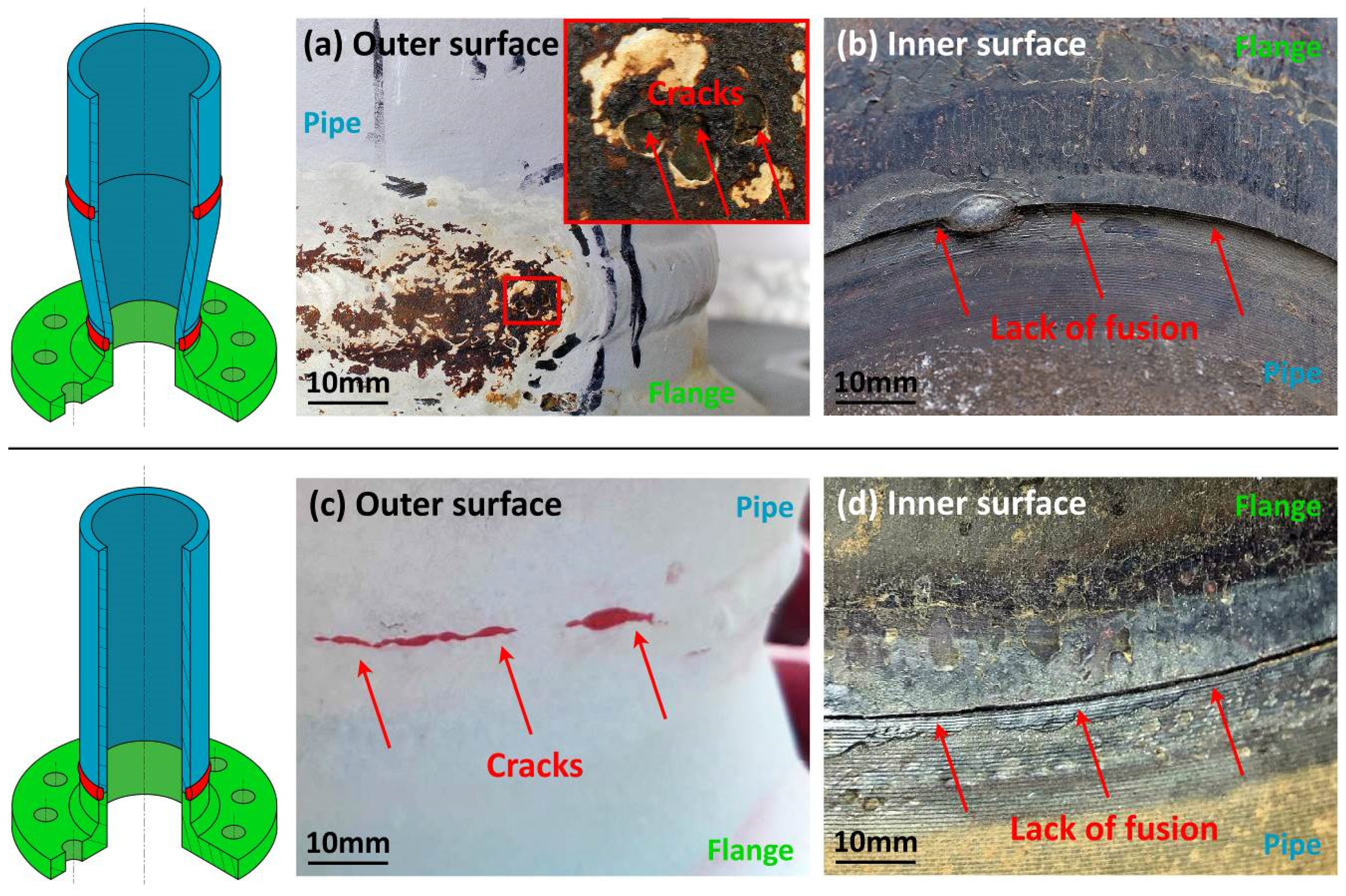
3.1. Fractographic Analysis

The investigation was concentrated on Circuit n.2, where some leaks were detected. As reported in Figure 2, the outer surface displayed some cracks, both on the welded and the heat-affected zones. The inner surface, instead, showed a step on the whole circumference in the contact region between the welded parts. Figure 3 denotes the presence of many corrosion pits in the region next to the welding bead. Away from the welded zone, the inner pipe and flange surfaces are free from corrosion defects.
The radiographic investigation (Figure 4) revealed that the cracks observed on the outer surface extended through the whole thickness and were characterized by many branches. Further, the X-ray analysis demonstrated a critical welding defect, i.e., the lack of fusion along the whole circumference. These defects generated a narrow gap between the pipe and flange edges, enhancing the development of many corrosion pits with a size between 0.5 mm and 2 mm.
The observation of the fractured surfaces was performed using SEM on two areas: the first one is the region characterized by the step between the two welded edges, whereas the second one is close to the observed cracks. These analyses are shown in Figure 5 and Figure 6, respectively.

3.2. Chemical and Microstructural Analysis

The chemical analyses of the pipe and the flange steels were carried out using the OES technique. The results, reported in Table 1, are compliant with the EN 1092-1 and EN 10222-2 standards for the flange as well as the EN 10216-1 standard for the pipe.
Table 2 reports the chemical analysis of the fluid in the cooling system when the first leaks were detected. It was performed using the ICP-MS technique on samples taken in two different parts of the plant. It revealed acceptable values of the pH (very close to 7) and of the molybdate content (higher than 160 ppm as recommended by the producer). Only the iron content was particularly high because of the ongoing corrosion process. One of the sections taken in the cracked area was subjected to a metallographic investigation. The specimens were mirror polished according to the standard metallographic technique and then etched using Nital 2% reagent for 15 s. Using LOM, the specimens were observed both before and after chemical etching, as reported in Figure 7 and Figure 8.
The pictures in Figure 7 and Figure 8 showed that the crack path is both trans- and inter-granular with many secondary branches. From a microstructural point of view, both the base materials are prevalently ferritic, even if the flange ferrite content is slightly lower and its grain size is slightly finer than the pipe’s (15–20 μm and 25–40 μm, respectively) [17].
In the heat-affected and welded zones, both the flange and the pipe microstructures are characterized by ferrite and pearlite with morphologies different from the base metal’s because of the fast cooling rates. No bainite or martensite were detected. The metallographic analysis confirms the lack of fusion during the welding operation. The pipe surface next to the welding bead is covered by a 20–30 μm thick oxide, below which 10–30 μm deep corrosion pits are visible. Moreover, a 150 μm deep inter-granular crack was generated from one of them as shown in Figure 7d.
After the metallographic investigation, HV0.3 micro-hardness tests were performed on the etched section. The whole welded joint was considered, with particular attention to the base metal, heat-affected and melted zones. The results are reported in Figure 9. The base metal’s hardness is compatible with that of general-purpose steels such as the P235TR2 and P245GH grades. The heat-affected and welded zone data are higher than those of the base metal’s (but the difference is always lower than 100 HV), even if their values are justified by the thermal cycle induced by the welding operation.

3.3. Physical Model of the Observed Damage

The root cause of the leaks observed next to the welding bead was related to crevice corrosion and pitting, as demonstrated by the experimental analyses. The first mechanism was observed in the narrow gap between the flange and the pipe edges due to the lack of fusion during the welding operation. The second initiation mechanism was instead responsible for the defects located in the areas close to the welding bead.
Some authors [18,19,20,21] have studied the micro-mechanisms of pitting and crevice corrosion focusing their attention on the nano-porosity and stress induced by the release of one (or more) alloying element(s) during the corrosion process. The combination of these micro-defects and tensile stress can cause cracking phenomena, often related to particular crystallographic directions. There is general agreement on the beneficial effects of corrosion inhibitors, even if fast localized corrosion can start when the protective layer fails. This may happen both with inorganic and organic (such as silane, thiol, selenol and ABT) inhibitors. The use of organic molecules as corrosion inhibitors is also becoming increasingly popular because they are considered to have a lower environmental impact. The available data show that organic inhibitors protect metals by forming a film after having been absorbed on the metal’s surface [22]. However, as described in the technical literature [23], passive film breakdown can occur according to three main mechanisms, i.e., by film penetration, adsorption and breaking. In many cases, a combination of these mechanisms may activate depending on the metal/environment system. Reduced effectiveness and the breakdown of the protective film is one of the key points also described in the failure analysis since the damage occurred in the circuit where the corrosion inhibitor was added. The presence of localized micro- and nano-porosity can, in fact, work as a microscopic stress raiser that can amplify the effect of existing tensile stresses and, finally, induce and accelerate the onset of stress corrosion cracking.
This kind of corrosion is particularly severe and creates cracks often characterized by secondary branches. The crack path can be either trans- or inter-granular, and sometimes both the features are present. According to the literature, the stress corrosion cracking of steels occurs when three conditions are present:
  • Steel with a low carbon content;
  • A specific corrosive environment, usually weakly acidic or basic;
  • Tensile stresses due to external forces or residual stresses.
The most common SCC cases occur at temperatures higher than 30 °C and can be accelerated by the presence of chloride ions [24,25,26].
In the investigated failure, all the previous conditions are verified, but what is still not completely explained are the different behaviors of Circuits n.1 and n.2. Considering that the corrosive phenomena acting in the circuits, especially in the crevice zone, are many and complicated, the authors proposed a physical model to describe the fast damage development in Circuit n.2.
Assuming the same amount of oxygen dissolved in the working fluid, the same geometrical characteristics (in particular the presence of the crevice due to the lack of fusion) and the same stress conditions for both the systems, the main difference is the presence of the inhibitor in Circuit n.2. The corrosion phenomenon developed in Circuit n.1 can be described in the following points:
  • In Circuit n.1, initially, the oxygen present in the working fluid is in contact with the pipes’ inner surfaces. It can be assumed that it is present in the crevice as well. From a mechanical point of view, a tensile stress exists, mainly due to the residual welding stresses. The combination of these stresses and the crevice length can be described by the fracture mechanic parameter KI, the stress intensity factor, that allows a better understanding of the phenomena occurring in this zone.
    The initial value of the stress intensity factor did not exceed the critical value KIC; otherwise, unstable fracture would have occurred immediately.
  • From time zero on, the corrosion of both the pipes’ inner surfaces and the crevice occurs because of the cathodic reaction of oxygen until, after a certain time, the oxygen at the crevice tip is totally consumed. The one in the remaining part of the system decreases too, but it is still present. In this moment, the conditions for crevice corrosion activation exist due to the different oxygen concentrations at the crevice tip and mouth. The pipes’ surfaces will show uniform or quasi-uniform corrosion, while the crevice depth will increase, leading to an increment of the applied stress intensity factor.
  • In the crevice zone, the corrosion is more severe because of the potential difference between the tip and the outer areas. As time passes, the amount of free oxygen in the circuit decreases since it is consumed by the electrochemical reactions with the steel pipes. Since the oxygen content is decreasing, the corrosion intensity at the crevice tip will also reduce gradually.
  • When the stress intensity factor increases, stress corrosion cracking can be activated. The technical literature [24] states that crack propagation can occur even when the applied KI values are lower or much lower than KIC if the environment is aggressive. In this condition, the crack propagation rate da/dt depends on the applied KI, as shown in Figure 10.
Two instances may occur:
  • KI ≥ KISCC. The stress corrosion phenomenon is activated and contributes to the final damage;
  • KI < KISCC. No SCC damage occurs.
  • When the oxygen is totally consumed by the reactions between the fluid and the pipe’s surface, the crevice effect is deactivated too. If the SCC phenomenon was started, the crack can grow according to the applied KI; otherwise, the corrosion phenomena stop. Finally, it is important to remark that the oxygen present in the circuit is consumed quickly because of the generalized corrosion occurring on the wide steel surfaces. This means that crevice corrosion can also work for a short time; hence, the onset of the SCC phenomenon is unlikely. The corrosion process can restart if new fluid is added in the circuit.
Circuit n.2 is characterized by the presence of the inhibitor. The main differences between Circuits n.1 and n.2 are described in the following points:
  • At time zero, it can be assumed that Circuit n.2 and Circuit n.1 have the same amount of oxygen in the fluid and that both the oxygen and the inhibitor are present in the crevice. As said before, it is possible to state that a stress intensity factor KI is applied due to the tensile stress induced by the welding operation.
    Furthermore, in this case, this value is not over the critical stress intensity factor KIC; otherwise, unstable fracture would have occurred immediately;
  • From time zero on, the corrosion process can start in both the pipes’ surfaces and the crevice because of the cathodic reaction of oxygen. When the passivation occurs due to the formation of FeMoO4 [11], the corrosion aggression stops;
  • As described in the technical literature [26,27,28] and confirmed by the producer recommendations, the inhibitor’s efficacy decreases over time, and the amount present in the crevice cannot be replaced by that present in the fluid since it cannot circulate in the crevice freely [29,30,31]. When the protection finally disappears, crevice corrosion can start because of the different electrochemical conditions at the crevice tip and mouth. Differently from Circuit n.1, the outer oxygen content does not decrease or decreases very slowly, since it cannot react with the pipes’ surfaces that are now protected by the iron molybdate layer. The corrosion conditions can be worsened further because of the large potential difference between the pipes’ inner walls and the crevice tip. In fact, when a steel surface is protected by a molybdate layer, its nobility increases significantly [26], promoting critical corrosion phenomena;
  • During this severe corrosion attack, the crevice depth extended continuously. In comparison with Circuit n.1, it is possible to state that the stress intensity factor applied in Circuit n.2 increases faster and for a longer time, since the adherent iron molybdate layer present on the pipes’ inner surfaces prevents the total consumption of oxygen. The ongoing crevice corrosion extends the crevice length until the applied stress intensity factor can reach and exceed the material KISCC. As soon as this happens, the stress corrosion cracking phenomenon starts finally, justifying the shorter working life of Circuit n.2.
The described mechanisms can also explain the SCC cracks shown in Figure 7d. The iron oxide generated during welding prevented the correct formation of the molybdate-rich layer on the heat-affected zone surface. This generated a strong potential difference between this area and the neighboring zones where the inhibitor worked correctly. Under such conditions, pitting corrosion can activate, as demonstrated by the observed pits. Moreover, the local composition of the fluid changes according to the well-known phenomena associated with this corrosion type [32,33].

4. Conclusions

The leaks and cracks observed in the investigated cooling circuit were caused by stress corrosion cracking phenomena. The initiation mechanisms can be associated with crevice corrosion where the lack of fusion generated a narrow space and with the pitting where a residual amount of iron oxide scale prevented the correct formation of the protective iron molybdate layer. Moreover, next to the weld, the observed geometrical discontinuities (crevices, steps, oxide layers, and lack of fusion) caused some stagnation zones and turbulence of the working fluid. These factors hindered or even prevented the formation of the passive layer induced by the molybdate-based corrosion inhibitor. The key role played by the inhibitor is confirmed by the fact that only one of the cooling circuits failed.
A physical model was proposed to explain and justify the damage described in the present paper. It is compatible with other failures described in the technical literature, especially when a solution containing sodium molybdate-based inhibitor is employed. The presence of passivated surfaces, in fact, amplifies the severe corrosion phenomena occurring where the surface is not protected. This, in turn, activates stress corrosion cracking when sufficient stress is present. The investigation of such damage mechanisms could take advantage of the determination of the residual stresses induced by the welding and by the precise measurement of the geometrical defects, such as the one generated by the lack of fusion. Nevertheless, both these analyses can hardly be performed, since residual stress determination is very complicated when the fluid is circulating; even if the plant is stopped, the test cannot be carried out easily because of the component geometry. In addition to the previous observations, the residual stresses acting in the inner part of the pipes and flanges cannot be measured without cutting the welded joint. Furthermore, the determination of the depth of possible geometrical defects due to the welding operation is challenging since it cannot be examined on-site accurately. In order to investigate the interaction between one inhibitor (not necessarily molybdate-based), the presence of narrow geometrical defects and the corrosion rate and type, one or more laboratory systems should be prepared after a careful study of the geometrical and experimental conditions. These things considered, in the case of circuits working in an industrial environment, some recommendations can help the circuit manufacturer prevent the serious corrosion damage described in this work: The welded zone must be free of defects, especially the ones that can generate narrow spaces and geometrical discontinuities on the inner surfaces of the cooling circuit. After welding, a stress relieving treatment can improve corrosion resistance since the residual stresses are completely removed. Moreover, a periodic and standardized control of the working solution chemical composition should be performed in order to guarantee that the inhibitor content is higher than the minimum amount suggested by the producer. Such controls are also useful to determine the amount of free iron that can be easily related to possible ongoing corrosion processes.

Author Contributions

Conceptualization, M.V.B., A.C., B.R., R.G. and F.I.; Methodology, M.V.B., A.C., B.R., R.G. and F.I.; Investigation, M.V.B., A.C., B.R., R.G. and F.I.; Resources, M.V.B., A.C., B.R., R.G. and F.I.; Data curation, M.V.B., A.C., B.R., R.G. and F.I.; Writing, M.V.B., A.C., B.R., R.G. and F.I.; Writing Review and Editing, M.V.B., A.C., B.R., R.G. and F.I. All authors have read and agreed to the published version of the manuscript.

Funding

This research received no external funding.

Conflicts of Interest

The authors declare no conflict of interest.

Nomenclature

BM1Base metal—Pipe side
HAZ1Heat-affected zone—Pipe side
MZ1Melted zone—Pipe side
BM2Base metal—Flange side
HAZ2Heat-affected zone—Flange side
MZ2Melted zone—At the crevice tip
HV0.3Micro-hardness value—Load equal to 300 gf
SCCStress corrosion cracking
KIStress intensity factor in Loading mode I
KICFracture toughness in Loading mode I
KISCCCritical stress intensity factor under SCC conditions
da/dtCrack growth rate

References

  1. Silberstein, E. Heat Pumps; Cengage Learning: Boston, MA, USA, 2015; ISBN 9781305445437. [Google Scholar]
  2. Prelas, M.A.; Ghosh, T.K. Energy Resources and Systems: Volume 1: Fundamentals and Non-Renewable Resources; Springer: Berlin/Heidelberg, Germany, 2009; ISBN 9789048123827. [Google Scholar]
  3. Penoncello, S.G. Thermal Energy Systems: Design and Analysis, 2nd ed.; CRC Press: Boca Raton, FL, USA, 2018; ISBN 9781351736572. [Google Scholar]
  4. Sastri, V.S. Green Corrosion Inhibitors: Theory and Practice; Wiley: Hoboken, NJ, USA, 2012; ISBN 9781118015414. [Google Scholar]
  5. Leonard, P.G.; Satani, N.; Maxwell, D.; Lin, Y.H.; Hammoudi, N.; Peng, Z.; Pisaneschi, F.; Link, T.M.; Lee, I.V.G.R.; Sun, D.; et al. SF2312 is a natural phosphonate inhibitor of enolase. Nat. Chem. Biol. 2016, 12, 1053–1058. [Google Scholar] [CrossRef]
  6. Fathabadi, H.E.; Ghorbani, M.; Mokarami Ghartavol, H. Corrosion Inhibition of Mild Steel with Tolyltriazole. Mater. Res. 2021, 24, 1–16. [Google Scholar] [CrossRef]
  7. Stranick, M.A. The corrosion inhibition of metals by molybdate Part I. Mild Steel Corros. 1984, 40, 296. [Google Scholar] [CrossRef]
  8. Rey, S.; Gary, M.R. Molybdate and Non-Molybdate Options for Closed Systems; Association of Water Technologies: Rockville, MD, USA, 2005. [Google Scholar]
  9. Ente Italiano di Normazione. Tubi di Acciaio Senza Saldatura per Impieghi a Pressione—Condizioni Tecniche di Fornitura—Parte 1: Tubi di Acciaio Non Legato per Impieghi a Temperatura Ambiente UNI EN 10216-1:2014; Ente Italiano di Normazione: Milano, Italy, 2014. [Google Scholar]
  10. Ente Italiano di Normazione. Fucinati di Acciaio per Apparecchi a Pressione—Parte 2: Acciai Ferritici e Martensitici Aventi Caratteristiche Specifiche a Temperatura Elevata UNI EN 10222-2:2021; Ente Italiano di Normazione: Milano, Italy, 2021. [Google Scholar]
  11. Trela, J.; Chat, M.; Scendo, M.; Kochanowski, J. Influence of sodium molybdate (VI) on the corrosion of S235 carbon steel. CHEMIK 2015, 69, 592–599. [Google Scholar]
  12. Stephen, D.C.; Bernard, S.C., Jr. ASM handbook, Vol. 13. Corrosion. Materials Park (Ohio); ASM International: Almere, The Netherlands, 1997. [Google Scholar]
  13. Allertshammer, W. The role of molybdate-containing inhibitors in cases of stress corrosion cracking in closed water circuits. Mater. Corros. 2021, 72, 528–533. [Google Scholar] [CrossRef]
  14. McGehee, A. Effect of Water Chemistry on Stress Corrosion Cracking (SCC) in Low Alloy Steels, 1011867, Technical Update; EPRI Electric Power Research Institute: Palo Alto, CA, 2005; pp. 91395–94304. [Google Scholar]
  15. George, F.V.V. ASM Handbook, Vol. 09. Metallography and Microstructures. Materials Park (Ohio); ASM International: Almere, The Netherlands, 1997. [Google Scholar]
  16. Thomas, J.B.; Ryan, D.; Jeffrey, A.J.; Erik, M.; George, F.V.V.; Dehua, Y. ASM Handbook, Vol. 10. Material Characterization. Materials Park (Ohio); ASM International: Almere, The Netherlands, 1997. [Google Scholar]
  17. Durand-Charre, M. Microstructure of Steels and Cast Irons; Springer: Berlin/Heidelberg, Germany, 2004; ISBN 9783540209638. [Google Scholar]
  18. Renner, F.U.; Ankah, G.N.; Bashir, A.; Ma, D.; Biedermann, P.U.; Shrestha, B.R.; Nellessen, M.; Khorashadizadeh, A.; Losada-Pérez, P.; Duarte, M.J.; et al. Star-Shaped Crystallographic Cracking of Localized Nanoporous Defects. Adv. Mater. 2015, 27, 4877–4882. [Google Scholar] [CrossRef]
  19. Neupane, S.; Rivas, N.A.; Losada-Pérez, P.; D’Haen, J.; Noei, H.; Keller, T.F.; Stierle, A.; Rudolph, M.; Terfort, A.; Bertran, O.; et al. A model study on controlling dealloying corrosion attack by lateral modification of surfatant inhibitors. Mater. Degrad. 2021, 5, 29. [Google Scholar] [CrossRef]
  20. Pareek, A.; Borodin, S.; Bashir, A.; Ankah, G.N.; Keil, P.; Eckstein, G.A.; Rohwerder, M.; Stratmann, M.; Gr, Y.; Renner, F.U. Initiation and Inhibition of Dealloying of Single Crystalline Cu3Au (111) Surfaces. J. Am. Chem. Soc. 2011, 133, 18264–18271. [Google Scholar] [CrossRef]
  21. Chen, X.; Karasz, E.; Badwe, N.; Sieradzki, K. Dynamic fracture and dealloying induced stress-corrosion cracking. Corros. Sci. 2021, 187, 109503. [Google Scholar] [CrossRef]
  22. Jafari, H.; Akbarzade, K.; Danaee, I. Corrosion inhibition of carbon steel immersed in a 1 M HCl solution using benzothiazole derivatives. Arab. J. Chem. 2019, 12, 1387–1394. [Google Scholar] [CrossRef] [Green Version]
  23. Frankel, G.S. Pitting Corrosion of Metals: A Review of the Critical Factors. J. Electrochem. Soc. 1998, 145, 2186. [Google Scholar] [CrossRef]
  24. Henthorne, M.; Parkins, R.N. Some aspects of stress-corrosion crack propagation in mild steel. Corros. Sci. 1966, 6, 357–369. [Google Scholar] [CrossRef]
  25. Henthorne, M.; Parkins, R.N. Some aspects of the influence of structure upon stress-corrosion cracking and grain boundary corrosion in mild steels. Br. Corros. J. 1967, 2, 186–192. [Google Scholar] [CrossRef]
  26. Parkins, R.N. Mechanistic aspects of intergranular stress corrosion cracking of ferritic steels. Corrosion 1996, 52, 363–374. [Google Scholar] [CrossRef]
  27. Shaw, B.A. ASM Handbook, Volume 13A: Corrosion: Fundamentals, Testing, and Protection; Cramer, S.D., Covino, B.S., Jr., Eds.; ASM International: Almere, The Netherlands, 2003. [Google Scholar]
  28. El Din, A.S.; Wang, L. Mechanism of corrosion inhibition by sodium molybdate. Desalination 1996, 107, 29–43. [Google Scholar] [CrossRef]
  29. Tan, Y.J.; Bailey, S.; Kinsella, B. The monitoring of the formation and destruction of corrosion inhibitor films using electrochemical noise analysis (ENA). Corros. Sci. 1996, 38, 1681–1695. [Google Scholar] [CrossRef]
  30. Chen, Y.; Hong, T.; Gopal, M.; Jepson, W.P. EIS studies of a corrosion inhibitor behaviour under multiphase flow conditions. Corros. Sci. 2000, 42, 979–990. [Google Scholar] [CrossRef]
  31. Askari, M.; Aliofkhazraei, M.; Ghaffari, S.; Hajizadeh, A. Film former corrosion inhibitors for oil and gas pipelines—A technical review. J. Nat. Gas Sci. Eng. 2018, 58, 92–114. [Google Scholar] [CrossRef]
  32. Chatterjee, U.K.; Singh Raman, R.K. Stress corrosion cracking (SCC) in low and medium strength carbon steels. Stress Corros. Crack. 2011, 169–198. [Google Scholar]
  33. Sieradzki, K.; Newman, R.C. Stress-corrosion cracking. J. Phys. Chem. Solids 1987, 48, 1101–1113. [Google Scholar] [CrossRef]
Figure 1. Drawings of the two types of welded joints under investigation. In Figure (a,b), the welded zones are in red. The thickness of the pipes is 5 mm, and the outer diameters are 110 mm (a) and 100 mm (b). The lengths of the two parts taken from Circuit n.2 are about 500 mm.
Metals 13 00723 g001
Figure 2. Outer and inner surfaces of the two types of welded joints under investigation. Cracks next to the welding bead are clearly visible in pictures (a,c). Pictures (b,d) show the lack of fusion and the step in the contact region between the welded parts.
Metals 13 00723 g002
Figure 3. Joints’ inner surfaces after cleaning. Pictures show the step between the welded edges; pitting and crevice corrosion are highlighted with red and orange arrows, respectively.
Metals 13 00723 g003
Figure 4. X-ray analysis. Welds are characterized by lack of fusion that generated crevice corrosion between the pipe and flange edges (orange arrows). Branched cracks are visible in welded area and heat-affected zone (red arrows).
Metals 13 00723 g004
Figure 5. SEM investigation of the region characterized by the step between the two welded edges. Picture (a) shows lack of fusion and crevice. Picture (b) shows some of the observed corrosion pits.
Metals 13 00723 g005
Figure 6. SEM analysis of one cracked area. Cracks are characterized by many branches and corrosion cavities. Images (b,c) are magnifications of picture (a).
Metals 13 00723 g006
Figure 7. Metallographic analysis of one cracked region. All the cracks have a high number of secondary branches. Pictures (a,b) are magnifications of Zone 1, and pictures (c,d) are magnifications of Zone 2.
Metals 13 00723 g007
Figure 8. Metallographic analysis of one cracked region after etching using Nital 2% reagent. Bainitic microstructures characterize the heat-affected and melted zones. A branched crack is clearly visible at the crevice tip (MZ2).
Metals 13 00723 g008
Figure 9. HV0.3 micro-hardness values obtained in the base metal and the heat-affected and welded zones. The micro-hardness values in the heat-affected and melted zones are higher than those of the base metal’s according to the observed microstructure shown in Figure 8.
Metals 13 00723 g009
Figure 10. Relation between the stress intensity factor and the crack growth rate.
Metals 13 00723 g010
Table 1. Chemical analyses of the investigated steels.
%C%Si%Mn%P%S%Cr%Cu%Mo%Nb%Ni%Ti%VCE
Flange 10.170.361.290.0250.0150.010.020.001<0.00030.010.0030.020.39
Flange 20.200.180.390.0240.0090.030.010.002<0.00030.010.0040.010.27
P245GH
EN 10222-2
0.08
0.20
0.40
Max
0.50
1.30
0.025
Max
0.015
Max
0.30
Max
0.30
Max
0.08
Max
0.01
Max
0.30
Max
0.03
Max
0.02
Max
0.41
Max
Pipe 10.090.200.530.0160.0030.130.170.06<0.00030.150.002<0.00030.24
Pipe 20.080.240.420.0150.0020.090.150.03<0.00030.070.0020.0070.19
P235TR2
EN 10216-1
0.16
Max
0.35
Max
1.20
Max
0.025
Max
0.015
Max
0.30
Max
0.30
Max
0.08
Max
0.01
Max
0.30
Max
0.04
Max
0.02
Max
---
Table 2. Chemical analysis of two samples taken from the solution present inside the cooling Circuit n.2.
Al [ppm]Ca
[ppm]
Mg
[ppm]
Fe
[ppm]
Cu
[ppm]
Zn
[ppm]
Cl
[ppm]
Molybdates
[ppm]
Ethylene Glycol
[Wt%]
pH
Sample 10.41071529.80.30.357481277.3
Sample 20.7901332.10.20.448503287.0
Reference values5
Max
150
Max
50
Max
5
Max
2
Max
3
Max
250
Max
160
Min
25
Min
6.5
7.5
Disclaimer/Publisher’s Note: The statements, opinions and data contained in all publications are solely those of the individual author(s) and contributor(s) and not of MDPI and/or the editor(s). MDPI and/or the editor(s) disclaim responsibility for any injury to people or property resulting from any ideas, methods, instructions or products referred to in the content.

