Article

Electrolyte Solvation Structure Manipulation and Synthetic Optimization for Enhanced Potassium Storage of Tin Phosphide/Carbon Alloy-Based Electrode

1
Guangdong Provincial Key Laboratory of Solid Wastes Pollution Control and Recycling, School of Environment and Energy, South China University of Technology, Guangzhou 510006, China
2
School of Metallurgy and Environment, Central South University, Changsha 410083, China
3
School of Chemical Engineering and Advanced Materials, Faculty of Sciences, Engineering and Technology, The University of Adelaide, Adelaide 5005, Australia
*
Author to whom correspondence should be addressed.
These authors contributed equally to this work.
Metals 2023, 13(4), 658; https://doi.org/10.3390/met13040658
Submission received: 24 February 2023 / Revised: 17 March 2023 / Accepted: 22 March 2023 / Published: 26 March 2023
(This article belongs to the Special Issue Developments on Sustainable Hydrometallurgical Methods)

Abstract

:
Phosphorus-based materials are considered to be reliable anode materials for potassium ion batteries (PIBs) due to their high theoretical capacity but suffer from inferior cycling stability and an unstable Solid Electrolyte Interface (SEI) layer. Herein, optimized ball-milled parameters and concentrated electrolytes are introduced to enhance the electrochemical performance of Sn4P3/C anodes. Consequently, the electrodes synthesized under optimized ball milling parameters could deliver a reversible capacity of 307.8 mA h g−1 in diluted Potassium hexafluorophosphate (KPF6) electrolyte. Moreover, compared with diluted bis(fluorosulfonyl)imide (KFSI) electrolyte, a robust inorganic KF-rich SEI layer can be formed on the electrode’s surface by employing concentrated KFSI electrolyte and provides more rapid K ion conduction rates. Meanwhile, a large proportion of the FSI anions participated in the K+ solvation shell when the KFSI concentration increased. As a result, high specific capacities (225.1 mA h g−1 at 50 mA g−1 after 200 cycles) and excellent Coulombic efficiency (97.24% at 500 mA g−1 after 200 cycles) can be achieved. This work may deepen our understanding of synthetic optimization in electrode material design and the role of concentrated electrolyte in tunning the solvation structure, and also offer an insightful clue to the design of high-capacity phosphorus-based anodes.

1. Introduction

Our ever-increasing consumption of non-renewable fossil energy and demand for electricity has driven the development of numerous types of electrical energy storage (EES) for large-scale applications due to their ability to compensate for the intermittence of renewable energy [1,2]. Recently, potassium ions as charge carriers have been utilized as potential future batteries due to the abundant potassium resources in the Earth’s crust (0.0017 wt. % for lithium and 1.5 wt. % for potassium) [3,4] and the relatively low standard hydrogen electrode of K/K+ (−2.93 V versus E0) [5,6]. Although potassium has a relatively large ionic radius (1.38 Å) compared with other alkali metal ions, K+ has weak Lewis acidity and leads to small Stokers’ radii (i.e., 3.6 Å in propylene carbonate) in solvents, which shows higher carrier mobility in electrolyte [7,8]. Therefore, it is meaningful to explore the potential applications of PIBs “beyond Li-ion” [9,10,11].
Among all the anode candidates for PIBs, Carbon-based electrode materials have outstanding cycling performance. However, due to the limited theoretical capacity provided by the KC8 reaction, the development of carbon-based electrode materials is hindered [6]. Considering the non-carbon-based electrode materials, Sn4P3 as phosphorus-based anodes have attracted enough attention due to their high capacity and the metallic feature of Sn to improve electrical conductivity. Zhang and co-workers investigated Sn4P3/C composite as an anode material for PIBs, which was synthesized using the ball-milling method and showed 384.8 mA h g−1 at 50 mA g−1 after 30 cycles [12]. However, the large volume variations upon cycling and the uncontrollable side reactions that happen at the electrode/electrolyte interface still hinder further applications [13,14,15]. For the preparation process, ball-milling is a good strategy for mass production of electrode materials, benefiting from its high operation flexibility, and low cost. However, due to the specific physical/chemical properties of phosphorus [12,16,17], the ball-milled parameters need to be optimized to prepare the Sn4P3. In terms of severe side reactions, the formation of the solid electrolyte interphase (SEI) layer is critical for governing electrochemical performance [18,19,20]. Past research has demonstrated how concentrated electrolyte and salt chemistry can be employed to significantly suppress side reactions and dendritic growth [21,22,23,24]. However, recent research on the Sn4P3 anode in PIBs has been more focused on adjusting the types of electrolytes, salts and additives, ignoring the significant effect of concentration and leading to unsatisfactory electrochemical performance compared with the theoretical values.
To address these issues, herein we prepared a Sn4P3/C composite via the scalable ball-milling method and further optimized the ball-milled parameters. The electrochemical performance of optimized ball-milled electrode materials was evaluated under various salt and concentrated electrolytes for PIBs. The cells in 2.5 M KFSI-Ethylene carbonate/Diethyl carbonate (EC/DEC) electrolyte delivered the best cycling performance among all the other electrolytes. For the K-metal symmetric electrodes, the cells in 2.5 M KFSI-EC/DEC showed relatively small hysteresis and overpotential, which indicated the small polarization in the electrolytes. Further investigation (e.g., X-ray Photoelectron Spectroscopy (XPS) and Fourier Transform Infrared Spectroscopy (FTIR)) revealed that an SEI layer with a high K–F content could be formed in highly concentrated KFSI electrolyte, which is more robust than those with less K–F content and organic ones. Moreover, a Density Functional Theory Molecular Dynamics (DFT-MD) simulation demonstrated that the FSI anion, EC and DEC molecules have stronger coordination as well as solvation ability with K+ as the KFSI concentration increased to 2.5 M, which is beneficial to forming an inorganic KF-rich SEI layer and preventing a side reaction from occurring. In this work, the strategy of controlling ball-milling parameters and electrolyte concentration, which is simple to operate, and easy to realize and industrialize, is applied to Sn4P3/C anode potassium ion batteries. A solid and uniform SEI layer is formed on the electrode’s surface to control the electrode’s volume change, protect the electrode’s integrity, and finally, achieve long cycling stability.

2. Materials and Methods

2.1. Materials

Potassium (K, ≥99.9%), tin power (Sn, ≥99.5%), red phosphorus (P, ≥98.5%), carbon black (C, ≥99.5%), potassium hexafluorophosphate (KPF6, ≥99%), potassium bis(fluorosulfonyl)imide (KFSI, ≥95%), ethylene carbonate (EC, ≥98%) and diethyl carbonate (DEC, ≥99%) were purchased from Aladdin, China. The other chemicals were purchased from Aladdin, China. All of the storage and handling of the samples was performed in an argon (Ar) filled glove box (MBraun Unilab, Garching, Germany) with the content of oxygen and water less than 0.01 ppm.

2.2. Synthesis of Sn4P3/C

Sn4P3/C composites were prepared according to the reported method [18,19]. Sn4P3/C powder was synthesized using a ball-milling process using elemental tin, red phosphorus, and carbon black as the raw materials in the weight ratio of Sn:P:C = 73.1:14.4:12.5 (with Sn and P in the molar ratio of 4:3, respectively). In this paper, it was synthesized using a ball-milling process using a planetary QM-QX4L ball mill under different parameters, as shown in Table S1.

2.3. Preparation of Electrolytes

All electrolytes were prepared in a glove box filled with argon and with an oxygen and water content of less than 0.01 ppm. The concentrations in this work were all marked in terms of the molarity of the salt with respect to the whole electrolyte volume. All concentrations of KPF6-EC/DEC and KFSI-EC/DEC were prepared with potassium hexafluorophosphate or potassium bis(fluorosulfonyl)imide in EC and DEC (in a volume ratio of 1:1).

2.4. Characterization

The crystal structures of the as-prepared powder were characterized using powder X-ray diffraction (XRD) on a GBC MMA diffractometer with a Cu Kα source at a scanning rate of 1° min−1. X-ray photoelectron spectroscopy (XPS) was conducted on a Phoibos100 photoelectron spectrometer using monochromatic Al Kα radiation under the vacuum of 2 × 10⁻⁶ Pa and the bottom pressure <10−8 mbar. The morphology of the synthesized materials and the cell poles were characterized using a JSM-7500FA field-emission scanning electron microscope (SEM). The chemical structure was collected using Raman microscopy (Raman, WITec alpha300R, German) with an excitation laser of 633 nm. The surface topography was detected using atomic force microscopy (AFM, Bruker ICON, German).

2.5. Electrochemical Measurements

Electrodes were fabricated using a slurry-coating method. All the synthesized materials (Sn4P3/C) were mixed with Super P carbon black and carboxymethyl cellulose (CMC) in the weight of 8:1:1, respectively. In addition, deionized water was used as the dispersing agent. All the materials were stirred for 12 h to form a slurry. After that, the slurry was coated with copper foil and dried in a vacuum oven at 90 degrees centigrade overnight. All batteries in this work were assembled with CR2036 type coin cases in an argon-purged glove box. A glass fiber membrane was used as the separator, while stainless steel shims and battery springs were introduced as supporters. Potassium metal was employed as the counter and reference electrode to assemble the half cells. The mass loading of the active materials (Sn4P3) was over 1.1 mg cm−2, corresponding to the total mass loading of 1.5 mg cm−2. The half cells were galvanostatic charged/discharged between 0.01 and 2.0 V versus K/K+ at various current densities on a Land battery tester. Symmetric K foil cells with the same area were tested in various electrolytes at the current density of 1 mA cm−2 with a stripping/plating capacity of 1 mA h cm−2. The specific capacity was calculated based on the weight of the Sn4P3.

2.6. Computational Method

Our calculations were performed by means of the density functional theory (DFT) using the Gaussian 09. The B3LYP (Becke, three-parameter, Lee-Yang-Parr) hybrid functional was used to calculate all molecular structures in GS and single states to describe the exchange correlation energy. The effective nuclear pseudo-potential was used to deal with the nuclear electrons. The basis set was used in the advanced B3LYP calculation of 6-311G++ (d, p) for the atoms including carbon, oxygen, nitrogen and hydrogen. To confirm that it was the energy minimum, a vibration analysis was performed at each rest point. The natural bond orbit method was also used for population analysis [25,26].
In the simulation, the solute and solvent composition were modeled and the COMPASS force field [27] was implemented to optimize the structure of interest. In general, the thermal vibration of the bulk atoms inside the solid is very small and can be ignored [28], so the bottom two glass atoms were fixed in their bulk positions. Electrostatic interactions were treated using the Ewald summation technique [29], and the Ewald accuracy was set to 4.184 × 10⁻⁴ kJ/mol. Van der Waals interactions are described using atom-based summation methods. The truncation distance, spline width, and buffer width were set to 15.5 Å, 1 Å, and 0.5 Å, respectively. The Andersen algorithm [30] was used to control the simulated temperatures at different levels. The MD simulations were performed under NVT integration with a time step of 1.0 fs and a total simulation time of 500 ps.

3. Results and Discussion

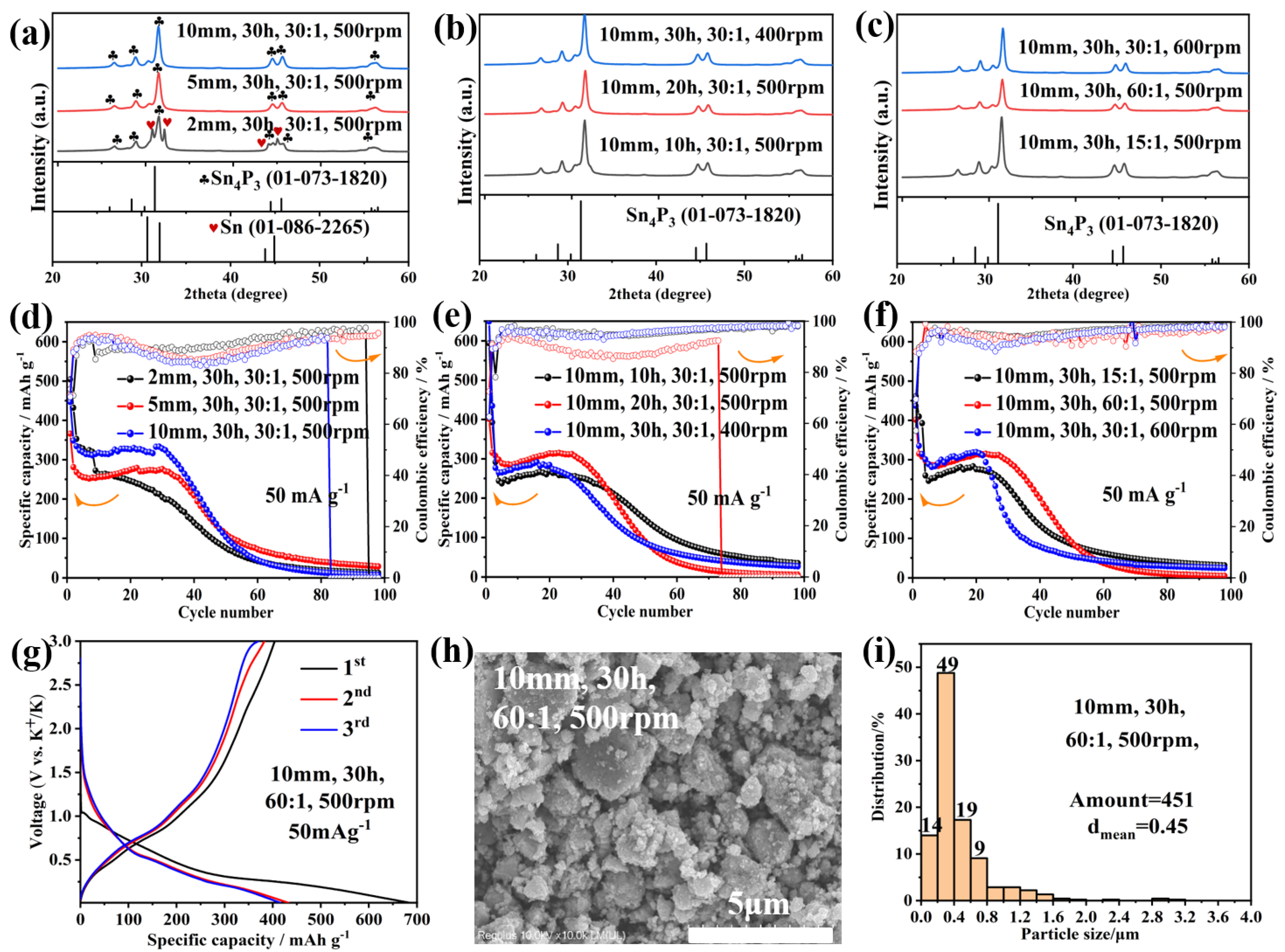
3.1. Optimization of Synthetic Parameters

Figure 1a–c showcases the X-ray diffraction (XRD) profiles of the Sn4P3/C materials. The representative peaks are indexed to the Sn4P3 phase (JCPDS no. 01-073-1820) and some residual metal tin phase (JCPDS no. 01-086-2265). The broad diffraction peak at approximately 25.4° indicates the presence of carbon black in the Sn4P3/C composites. In contrast, the XRD patterns show well-indexed peaks in the Sn4P3 phase when the sizes of the balls increased to 5 mm and 10 mm.
To optimize the synthetic parameters, the electrochemical performance of the Sn4P3/C composites as anodes were evaluated for PIBs using 2032-type coin cells. The cycling performances of the Sn4P3/C composite anode at 50 mA g−1 and 200 mA g−1 in 0.8 M KPF6 EC/DEC electrolyte are shown in Figure 1d–f and Figure S1. The specific capacity values of all the electrodes were determined based on the entire weight of the Sn4P3/C electrode. In general, the Sn4P3/C electrode exhibited a relatively stable specific capacity and maintained good cycle stability within 20–30 cycles. However, it suffered from severe capacity fading after 30 cycles, which may be due to the large volume expansion of the Sn4P3/C electrode material [31]. It is also worth mentioning that adjusting the ball-milling parameters can change the size and morphology of the milled products. In addition, a more uniform size and morphology can relieve the stress concentration caused by volume expansion and shorten the diffusion distance of the electron and potassium ion [32]. In Figure 1h, the SEM image shows the Sn4P3/C composites (10 mm, 30 h, 60:1, 400 rpm) are irregular agglomerated micrometer-sized particles, with an average particle size of 0.45 μm (Figure 1i). Figure 1h,i, Figure S2 and S3 reveal that the particle size and morphology of Sn4P3/C composites synthesized under the conditions of a 10 mm ball diameter, 30 h ball-milling time, 60:1 ball-to-powder ratio, and 400 rpm rotational speed are more uniform, and the purity is higher compared to other ball-milling parameters. The composites exhibit a relatively excellent discharge capacity of 307.8 mA h g−1 and a stable Coulombic efficiency (CE) of 94.68% over 30 cycles, as shown in Figure 1f. As shown in Figure 1g, Figure S4 and S5, the galvanostatic discharge/charge curves of the Sn4P3/C electrode for selected cycles in a potential range from 0.01 to 3.0 V vs. K+/K at 50 mA g−1 and 100 mA g−1. Figure 1g shows the initial CE of the electrode is 58.96% and the discharge capacity is 685.2 mA h g−1. The initial low CE and the large irreversible capacity may be caused by the incompletely reversible electrochemical process and the formation of the SEI layer.

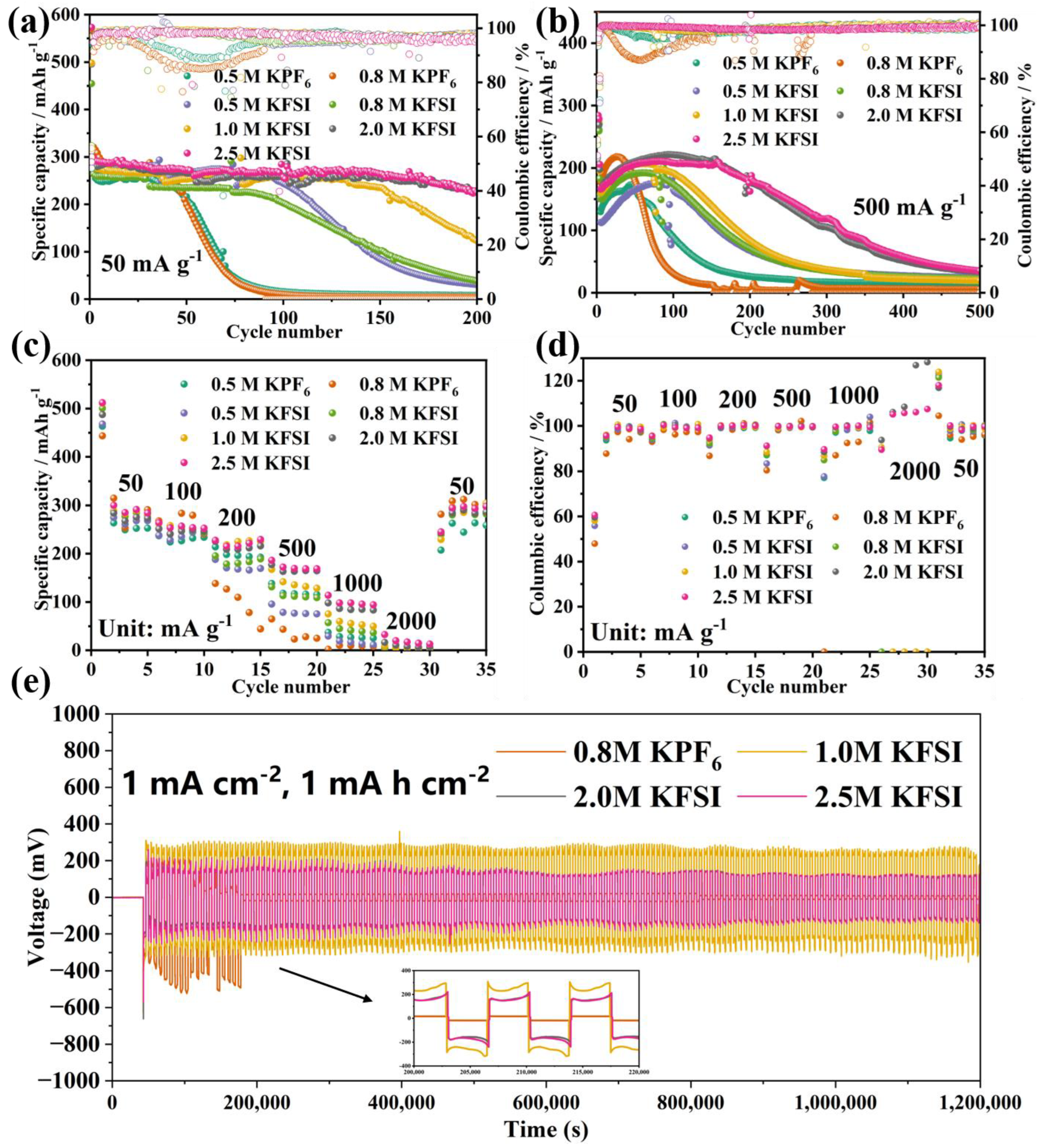
3.2. Regulation of Electrolytes

To design a highly concentrated electrolyte for PIBs, EC and DEC were used as solvents, while KPF6 and KFSI were employed as salts. The use of EC/DEC, as the most studied solvent combination, is advantageous for battery application. The high polarity and dielectric constant of EC contribute to SEI formation, while the low viscosity of DEC benefits from the K-ion’s mobility [33,34]. In addition, the salt anions in electrolytes participate in SEI formation and electronegativity adjustment.
The cycling stability and rate performance of Sn4P3/C in various electrolytes are compared in Figure 2. The corresponding charge/discharge profiles at different current densities are shown in Figures S6 and S7. As shown in Figure 2a,b, Sn4P3/C in 2.5 M KFSI EC/DEC exhibits excellent cycling stability at 50 mA g−1 and 500 mA g−1, respectively. It shows that the Sn4P3/C in 0.5 M and 0.8 M KPF6-based electrolytes achieved a similar initial capacity with other concentrated electrolytes but experienced severe capacity degradation, with <100 mAh g−1 remaining after 100 cycles. The cycling stability of Sn4P3/C is superior in the KFSI-based electrolyte compared to that in the KPF6-based electrolyte. Furthermore, the electrochemical performance of Sn4P3/C can be enhanced with an increase in electrolyte concentration. When the concentration of KFSI increased to 2.5 M, the cells achieved the best cycling performance and rate capability among all of the concentrated electrolytes. In Figure 2a,b, it can be observed that Sn4P3/C in 2.5 M KFSI exhibits the specific capacity of 225.1 mA h g−1 and 187.8 mA h g−1 as well as a CE of 95.65% and 97.24% at 50 mA g−1 and 500 mA g−1 after 200 cycles, respectively. In addition, as observed in Figures S6 and S7, Sn4P3/C in 2.5 M KFSI exhibits an initial CE of 50.61% and a discharge capacity of 573.2 mA h g−1 at 50 mA g−1, as well as 51.26% and 540.3 mA h g−1 at 500 mA g−1. In Figure 2c,d, the Sn4P3/C in 2.5 M KFSI delivers an average reversible capacity of 284.3 mA h g−1, 252.8 mA h g−1, 229.5 mA h g−1, 168.8 mA h g−1, 94.2 mA h g−1, 12.9 mA h g−1, 297.9 mA h g−1 with the current densities changing from 50 mA g−1, 100 mA g−1, 200 mA g−1, 500 mA g−1, 1000 mA g−1, 2000 mA g−1, 50 mA g−1, respectively. It is obvious that the corresponding capacity can be returned to the original level as the current density returns to 50 mA g−1.
Moreover, the symmetric K/K cells in 2.5 M KFSI-EC/DEC electrolyte at a current density of 1 mA cm−2 and a cycling capacity of 1 mA h cm−2 show relatively stable hysteresis and overpotential, indicating that placing cells in a higher concentration of KFSI is beneficial to the continuous formation of a robust SEI layer. In terms of the cells in the KPF6-based electrolyte and low concentrated KFSI-based electrolyte, larger fluctuations in the voltage profile occurred, which indicates the effect of polarization on rapid dendrite growth caused by the continuous formation of SEI layers [17]. All the results above are schematically illustrated in Figure 2e.

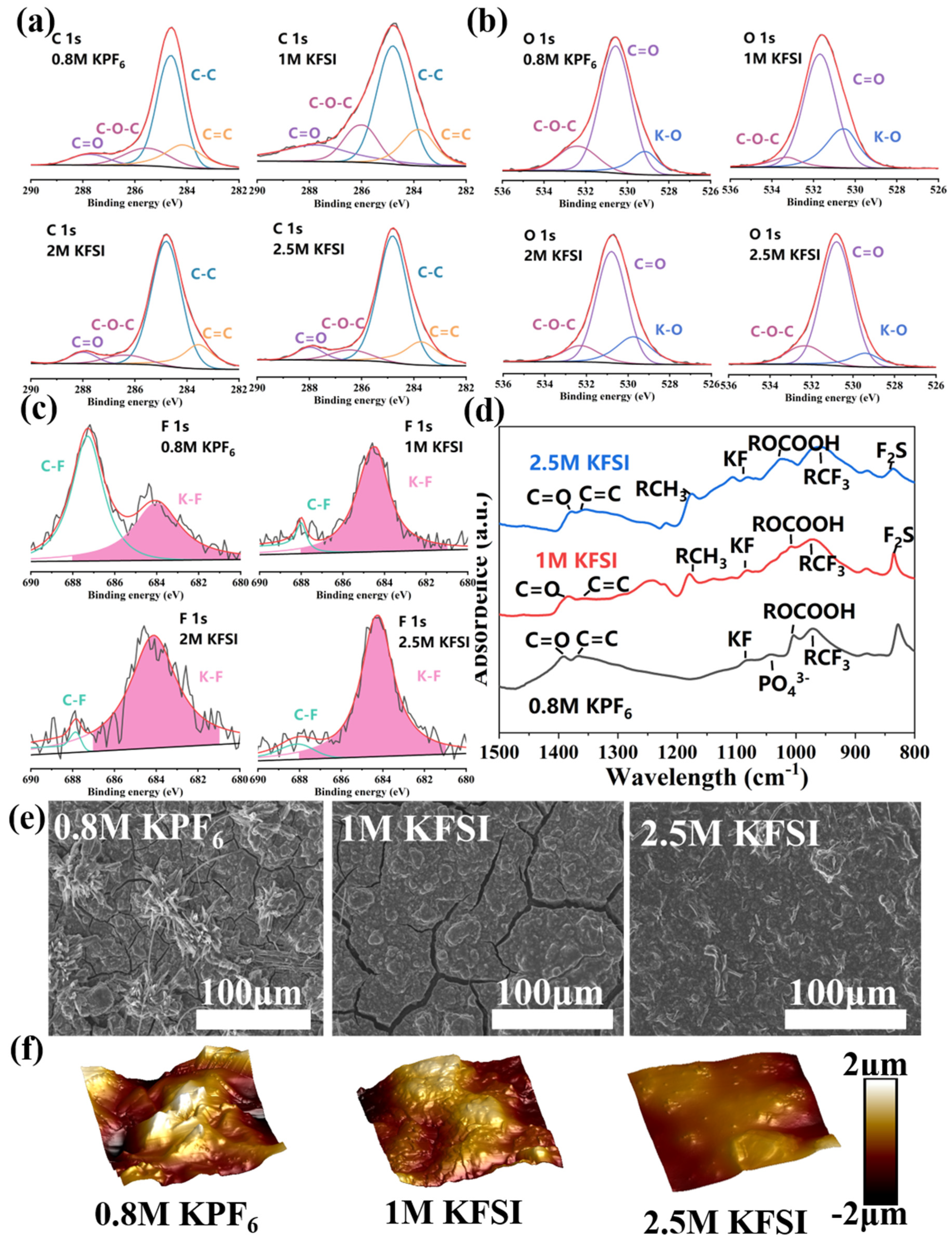
3.3. Analysis of SEI Layer Composition and Morphology

To explore the effect of electrolyte concentration on the stability of SEI layer, the cells were further characterized after five cycles. XPS was employed to understand the chemical composition of the SEI layers formed in the different electrolytes, and the results are presented in Figure 3a–c, the C 1s peak could be deconvoluted into four peaks corresponding to sp2 C (283.6 eV), sp3 C (284.8 eV), C-O-C (286.3 eV) and C=O (288.3 eV) species [35,36], indicating that the decomposition of solvent EC and DEC is one of the main sources of the derived SEI layer. Meanwhile, a new O 1s peak appeared, approximately in the range of 529 eV~531 eV, which can be attributed to K-O [37,38]. Figure 3c shows the F 1s signal could be detected at around 684.4 eV and 688.0 eV, corresponding to the inorganic K-F and organic C-F bonds, respectively [39]. By comparing peak intensities, it was observed that the intensity of the C-F bond on the surface of Sn4P3/C with 0.8 M KPF6-EC/DEC electrolyte was higher than that of the K-F bond. This indicates the formation of an organic-rich solid electrolyte interphase (SEI) layer in 0.8 M KPF6-EC/DEC electrolyte, which is likely due to solvent-induced reduction [40]. Conversely, the intensity of the K-F bond on the electrode surface in the KFSI electrolyte was higher than that in the KPF6 electrolyte, indicating a higher inorganic content in the SEI layer formed in the KFSI electrolyte. According to the XPS data, the ratios of inorganic K-F to organic C-F for the 0.8 M KPF6 in EC/DEC and the 1 M KFSI in EC/DEC electrolyte were as high as 1.389 and 2.381, respectively. In contrast, for the concentrated 2 M KFSI in EC/DEC and 2.5 M KFSI in EC/DEC electrolyte, the SEI layer possesses a ratio of inorganic K-F to organic C-F as high as 5.556 and 6.250, respectively. These results suggest that the solid electrolyte interphase (SEI) layer formed by concentrated electrolytes contains a higher proportion of inorganic components. Moreover, an increase in the concentration of the electrolyte salt results in a corresponding increase in the proportion of inorganic components present in the SEI layer. In particular, the Sn4P3/C with 2.5 M KFSI-EC/DEC showed the highest K-F intensities among the KFSI-based electrolytes, indicating that the SEI layer generated on the electrode’s surface in 2.5 M KFSI-EC/DEC electrolyte was more inclined to be an inorganic-rich layer. The inorganic SEI layer can contribute to the improvement of cycling stability, as it is well established that inorganic components have better mechanical strength than organic ones [41,42].
As shown in Figure 3e, the uniformity of the concentrated electrolyte-derived SEI was further verified using the ex situ SEM images. The cracks caused by using the tender SEI layer and irreversible volume expansion were observed on the electrode’s surface in 0.8 M KPF6 and 1.0 M KFSI electrolyte. On the contrary, there are barely any cracks on the electrode’s surface with the 2.5 M KFSI electrolyte, as observed in Figure 3e, probably because of the robust and uniform SEI layer that formed on the surface, which can protect the electrode and prevent excessive side reactions from occurring [43]. Meanwhile, the roughness and thickness of the SEI layers were examined using atomic force microscopy (AFM) synchronously. The brightness of the colors in the 3D images represent the height of the position. From the 3D images and roughness data, the electrode’s surface with an SEI derived from the concentrated 2.5 M KFSI in EC/DEC electrolyte is more uniform in comparison with the dilute 0.8 M KPF6 in EC/DEC and 1 M KFSI in EC/DEC electrolyte derived SEI layers, which are rougher. As we all know, an SEI layer with lower roughness is more stable and uniform, which helps to restrain excessive electrolyte decomposition and side reactions, and better protect the electrode [39].

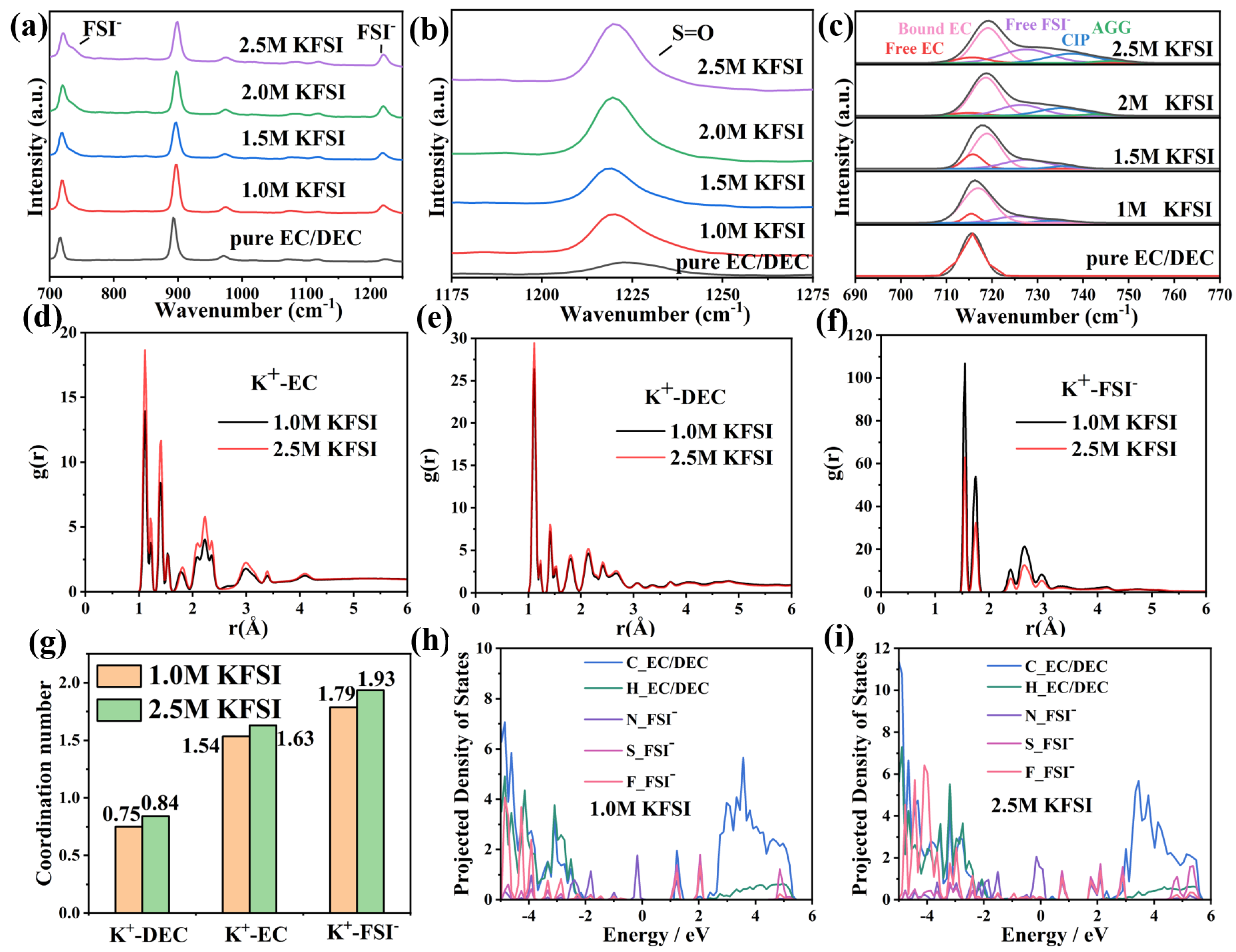
3.4. Analysis of Solvation Structure

The solution structure of the KFSI-EC/DEC electrolytes at different concentrations was characterized by Raman spectroscopy. The large right-tailing peak representing the S-N-S stretching vibration mode of the FSI anion (780–700 cm−1) is very sensitive to the difference in the K+ coordination [44]. As shown in Figure 4c, the percentage of free solvent EC molecules existed and became weaker with the increase in electrolyte concentration. Conversely, bound EC [45] and FSI existed in associated states, such as the contact ion pair (CIP) and ion aggregate (AGG) [46,47], becoming more evident with increasing KFSI concentration. Thus, the Raman results indicate that the coordination of K+ with both FSI- and EC becomes stronger at higher concentrations, and free solvent molecules are greatly reduced when the concentration reaches 2.5 M. This solvation structure can not only generate anion-derived inorganic-rich SEI protection, but also efficiently protect the electrolyte from the continuous reaction on the electrode surface.
MD simulation and DFT calculation were carried out to probe the solvation structure of the KFSI electrolytes. The radical distribution function (RDF) and corresponding coordination numbers of 1.0 M and 2.5 M KFSI-EC/DEC electrolyte further revealed the solvation shell structure and coordination ability of the central K+ with solvent molecules and the FSI anion under various concentrations of KSFI-EC/DEC electrolyte. It can be seen that the position of the first peaks corresponding to K+-EC, K+-DEC and K+-FSI were centered at about 1.11 Å, 1.11 Å and 1.55 Å, respectively. All the electrolytes possessed sharp peaks at 1.11 Å, indicating that their primary solvation shell of K+ contain EC and DEC. In addition, it is worth mentioning that there was another sharp peak at 1.55 Å (Figure 4f), demonstrating the presence of FSI near the solvated K+ ions to generate the denser anion-derived SEI layer protection and efficiently protect the electrolyte from continual reaction on the electrode’s surface. Compared with 1.0 M KSFI-EC/DEC, the corresponding coordination number in the 2.5 M KSFI-EC/DEC electrolyte is higher, which indicates that more DEC and EC molecules participated in the primary solvation with the K ions, while the FSI anion still “sticked” to the K+ ions and participated in the solvation shell (Figure 4g) [24]. As evidenced by the simulation of the projected density of states, in dilute concentration of KFSI (1.0 M), the energy level of the lowest occupied molecular orbital (LUMO), which is closely related to the electron-induced reduction, is located at around 1.0 eV and involves both the FSI- anions and the EC/DEC(Figure 4h). In contrast, the energy level of the LUMO in 2.5 M KFSI-EC/DEC electrolyte is located at around 1.5 eV, which is totally occupied by FSI- (Figure 4i). Meanwhile, the Gibbs free energy of K+-EC and K+-FSI (Figure S9) demonstrated that K+ prefers to coordinate with an FSI anion, which means there is a higher content of FSI than that of EC/DEC molecules in a K+ solvation structure. The theoretical results suggest that the SEI that forms in the dilute 1.0 M KFSI in EC/DEC electrolyte is mainly derived from the decomposition of both FSI anions and EC/DEC molecules, resulting in a non-uniform and non-stable SEI layer. In contrast, the SEI that forms in the concentrated 2.5 M KFSI in EC/DEC electrolyte is mainly derived from FSI- decomposition, leading to a uniform and stable SEI that could effectively suppress solvent decomposition and allow long cyclability [48,49].

3.5. Effect of Synthesis Parameters and Electrolyte Concentration

The above results indicate that both the synthesis parameters of the Sn4P3/C anode materials and the concentration of the electrolyte influence the cycling performance, as illustrated in Figure 5. Firstly, we screened the Sn4P3/C (10 mm, 30 h, 60:1, 500 rpm) composite with the best electrochemical performance by optimizing the synthesis parameters of ball-milling. Then, the combined theoretical and further experimental results suggested that, in a concentrated 2.5 M KFSI-EC/DEC system, the free solvent molecules reduced and the associated state FSI increased. This means that more FSI anions participate in the solvation shell with K+ and anion reduction is favored, leading to a robust and stable inorganic KF-rich SEI layer. This layer helps maintain the integrity of the electrode and significantly reduces electrolyte consumption. In addition, as shown in the MSD data (Figure S8), the K ion conduction in 2.5 M KFSI-EC/DEC electrolyte is faster than that of diluted KFSI-EC/DEC electrolyte during the cycling process. These results suggest that the presence of abundant K-containing inorganic compounds within the SEI layer can promote K ion migration, leading to enhanced electrochemical performance of the 2.5 M KFSI-EC/DEC electrolyte.

4. Conclusions

In summary, ball-milling and concentrated electrolyte were applied to a theoretical high specific capacity Sn4P3/C anode with the aim of addressing the volume variation caused by metal phosphides. In this work, the electrolyte solvation structure and the formation of the SEI layer were systematically studied under the various concentrated electrolytes. As a result, excellent cycling stability and high specific capacity were both achieved in the concentrated 2.5 M KFSI-EC/DEC electrolyte system. Concentrated KFSI-EC/DEC contributed to K ion solvation and an inorganic KF-rich SEI formation. The enhanced electrochemical performance mainly originated from the reduced volume variation and robust SEI layer derived from the manipulation of the ball-milling parameters and the concentration of electrolyte, which is good for protecting the integrity of the electrode and reducing electrolyte consumption. It is expected that the manipulation of both electrode preparation technology and concentrated electrolyte will shed light upon the multifunctionality of PIBs and will be appealing for low-cost and large-scale energy storage application.

Supplementary Materials

The following supporting information can be downloaded at: https://www.mdpi.com/article/10.3390/met13040658/s1. Table S1: Parameters of ball milling. Figure S1: Cycling performance of the Sn4P3/C electrodes in PIBs at the current density of 200 mA g−1. Figure S2: SEM images of Sn4P3/C composites under different ball milling parameters. Figure S3: Particle size distribution of Sn4P3/C composites under different ball milling parameters. Figure S4: The first, second and third discharge/charge profiles of PIBs with Sn4P3/C at the current density of 50 mA g−1. Figure S5: The first, second and third discharge/charge profiles of PIBs with Sn4P3/C at the current density of 200 mA g−1. Figure S6: The initial, second, and third discharge/charge profiles of Sn4P3/C anode with different electrolyte at 50 mA g−1 current density. Figure S7: The initial, second, and third discharge/charge profiles of Sn4P3/C anode with different electrolyte at 500 mA g−1 current density. Figure S8: Mean Square Displacement (MSD) of K+ in different electrolytes. Figure S9: Gibbs free energy of K+-EC and K+-FSI.

Author Contributions

Conceptualization, Z.F. and S.L.; methodology, Z.F.; software, Z.F.; validation, Z.F. and R.C.; formal analysis, Z.F. and R.H.; investigation, Z.F. and F.Z.; resources, Z.F. and W.L.; data curation, Z.F. and R.C.; writing—original draft preparation, Z.F. and R.C.; writing—review and editing, Z.F. and R.C.; visualization, Z.F. and R.H.; supervision, F.Z., W.L. and S.L.; project administration, F.Z., W.L. and S.L. All authors have read and agreed to the published version of the manuscript.

Funding

This work was supported by the Open Fund of Guangdong Provincial Key Laboratory of Solid Wastes Pollution Control and Recycling (2020B121201003).

Data Availability Statement

Data are contained within the article.

Conflicts of Interest

The authors declare no conflict of interest.

References

  1. Dunn, B.; Kamath., H.; Tarascon., J.-M. Electrical Energy Storage for the Grid: A Battery of Choices. Science 2011, 334, 928–935. [Google Scholar] [CrossRef] [PubMed] [Green Version]
  2. Chu, S.; Cui., Y.; Liu., N. The path towards sustainable energy. Nat. Mater. 2016, 16, 16–22. [Google Scholar] [CrossRef] [PubMed]
  3. Kim, H.; Kim, J.C.; Bianchini, M.; Seo, D.H.; Rodriguez-Garcia, J.; Ceder, G. Recent Progress and Perspective in Electrode Materials for K-Ion Batteries. Adv. Energy Mater. 2017, 8, 1702384. [Google Scholar] [CrossRef] [Green Version]
  4. Wu, X.; Leonard, D.P.; Ji, X. Emerging Non-Aqueous Potassium-Ion Batteries: Challenges and Opportunities. Chem. Mater. 2017, 29, 5031–5042. [Google Scholar] [CrossRef]
  5. Marcus, Y. Thermodynamic functions of transfer of single ions from water to nonaqueous and mixed solvents: Part 3-standard potentials of selected electrodes. Pure Appl. Chem. 2009, 57, 1129–1132. [Google Scholar] [CrossRef]
  6. Jian, Z.; Luo, W.; Ji, X. Carbon Electrodes for K-Ion Batteries. J. Am. Chem. Soc. 2015, 137, 11566–11569. [Google Scholar] [CrossRef]
  7. Matsuda, Y.; Nakashima, H.; Morita, M.; Takasu, Y. Behavior of Some Ions in Mixed Organic Electrolytes of High Energy Density Batteries. J. Electrochem. Soc. 1981, 128, 2552–2556. [Google Scholar] [CrossRef]
  8. Pham, T.A.; Kweon, K.E.; Samanta, A.; Lordi, V.; Pask, J.E. Solvation and Dynamics of Sodium and Potassium in Ethylene Carbonate from ab Initio Molecular Dynamics Simulations. J. Phys. Chem. C 2017, 121, 21913–21920. [Google Scholar] [CrossRef]
  9. Huang, H.; Xu, R.; Feng, Y.; Zeng, S.; Jiang, Y.; Wang, H.; Luo, W.; Yu, Y. Sodium/Potassium-Ion Batteries: Boosting the Rate Capability and Cycle Life by Combining Morphology, Defect and Structure Engineering. Adv. Mater. 2020, 32, e1904320. [Google Scholar] [CrossRef]
  10. Kubota, K.; Dahbi, M.; Hosaka, T.; Kumakura, S.; Komaba, S. Towards K-Ion and Na-Ion Batteries as “Beyond Li-Ion”. Chem. Rec. 2018, 18, 459–479. [Google Scholar] [CrossRef]
  11. Zhang, W.; Liu, Y.; Guo, Z. Approaching high-performance potassium-ion batteries via advanced design strategies and engineering. Sci. Adv. 2019, 5, eaav7412. [Google Scholar] [CrossRef] [PubMed] [Green Version]
  12. Zhang, W.; Mao, J.; Li, S.; Chen, Z.; Guo, Z. Phosphorus-Based Alloy Materials for Advanced Potassium-Ion Battery Anode. J. Am. Chem. Soc. 2017, 139, 3316–3319. [Google Scholar] [CrossRef] [PubMed] [Green Version]
  13. Chen, C.; Wang, Z.; Zhang, B.; Miao, L.; Cai, J.; Peng, L.; Huang, Y.; Jiang, J.; Huang, Y.; Zhang, L.; et al. Nitrogen-rich hard carbon as a highly durable anode for high-power potassium-ion batteries. Energy Storage Mater. 2017, 8, 161–168. [Google Scholar] [CrossRef]
  14. Sangster, J.M. K-P (Potassium-Phosphorus) System. J. Phase Equilibria Diffus. 2009, 31, 68–72. [Google Scholar] [CrossRef]
  15. Hosaka, T.; Kubota, K.; Hameed, A.S.; Komaba, S. Research Development on K-Ion Batteries. Chem. Rev. 2020, 120, 6358–6466. [Google Scholar] [CrossRef]
  16. Qian, J.; Wu, X.; Cao, Y.; Ai, X.; Yang, H. High capacity and rate capability of amorphous phosphorus for sodium ion batteries. Angew. Chem. Int. Ed. 2013, 52, 4633–4636. [Google Scholar] [CrossRef]
  17. Zhang, W.; Pang, W.K.; Sencadas, V.; Guo, Z. Understanding High-Energy-Density Sn4P3 Anodes for Potassium-Ion Batteries. Joule 2018, 2, 1534–1547. [Google Scholar] [CrossRef] [Green Version]
  18. Zhang, W.; Lu, J.; Guo, Z. Challenges and future perspectives on sodium and potassium ion batteries for grid-scale energy storage. Mater. Today 2021, 50, 400–417. [Google Scholar] [CrossRef]
  19. Zhou, M.; Bai, P.; Ji, X.; Yang, J.; Wang, C.; Xu, Y. Electrolytes and Interphases in Potassium Ion Batteries. Adv. Mater. 2021, 33, e2003741. [Google Scholar] [CrossRef]
  20. Zhang, F.; Zhang, W.; Wexler, D.; Guo, Z. Recent Progress and Future Advances on Aqueous Monovalent-Ion Batteries towards Safe and High-Power Energy Storage. Adv. Mater. 2022, 34, e2107965. [Google Scholar] [CrossRef]
  21. Zhao, J.; Zou, X.; Zhu, Y.; Xu, Y.; Wang, C. Electrochemical Intercalation of Potassium into Graphite. Adv. Funct. Mater. 2016, 26, 8103–8110. [Google Scholar] [CrossRef]
  22. Giffin, G.A. The role of concentration in electrolyte solutions for non-aqueous lithium-based batteries. Nat. Commun. 2022, 13, 5250. [Google Scholar] [CrossRef] [PubMed]
  23. Lee, S.; Park, H.; Rizell, J.; Kim, U.H.; Liu, Y.; Xu, X.; Xiong, S.; Matic, A.; Zikri, A.T.; Kang, H.; et al. High-Energy and Long-Lifespan Potassium–Sulfur Batteries Enabled by Concentrated Electrolyte. Adv. Funct. Mater. 2022, 32, 2209145. [Google Scholar] [CrossRef]
  24. Liu, S.; Mao, J.; Zhang, Q.; Wang, Z.; Pang, W.K.; Zhang, L.; Du, A.; Sencadas, V.; Zhang, W.; Guo, Z. An Intrinsically Non-flammable Electrolyte for High-Performance Potassium Batteries. Angew. Chem. Int. Ed. 2020, 59, 3638–3644. [Google Scholar] [CrossRef] [PubMed]
  25. Reed, A.E.; Curtiss, L.A.; Weinhold, F. Intermolecular Interactions from a Natural Bond Orbital, Donor-Acceptor Viewpoint. Chem. Rev. 1988, 88, 899–926. [Google Scholar] [CrossRef]
  26. McLean, A.D.; Chandler, G.S. Contracted Gaussian basis sets for molecular calculations. I. Second row atoms, Z = 11–18. J. Chem. Phys. 1980, 72, 5639–5648. [Google Scholar] [CrossRef]
  27. Sun, H.; Jin, Z.; Yang, C.; Akkermans, R.L.; Robertson, S.H.; Spenley, N.A.; Miller, S.; Todd, S.M. COMPASS II: Extended coverage for polymer and drug-like molecule databases. J. Mol. Model. 2016, 22, 47. [Google Scholar] [CrossRef]
  28. Wang, Z.; Gong, Y.; Jing, C.; Huang, H.; Li, H.; Zhang, S.; Gao, F. Synthesis of dibenzotriazole derivatives bearing alkylene linkers as corrosion inhibitors for copper in sodium chloride solution: A new thought for the design of organic inhibitors. Corros. Sci. 2016, 113, 64–77. [Google Scholar] [CrossRef]
  29. Ewald, P.P. Die Berechnung optischer und elektrostatischer Gitterpotentiale. Ann. Phys. 1921, 369, 253–287. [Google Scholar] [CrossRef] [Green Version]
  30. Grimme, S.; Antony, J.; Ehrlich, S.; Krieg, H. A consistent and accurate ab initio parametrization of density functional dispersion correction (DFT-D) for the 94 elements H-Pu. J. Chem. Phys. 2010, 132, 154104. [Google Scholar] [CrossRef] [Green Version]
  31. Wang, Q.; Zhao, X.; Ni, C.; Tian, H.; Li, J.; Zhang, Z.; Mao, S.X.; Wang, J.; Xu, Y. Reaction and Capacity-Fading Mechanisms of Tin Nanoparticles in Potassium-Ion Batteries. J. Phys. Chem. C 2017, 121, 12652–12657. [Google Scholar] [CrossRef]
  32. Li, D.; Zhang, Y.; Sun, Q.; Zhang, S.; Wang, Z.; Liang, Z.; Si, P.; Ci, L. Hierarchically porous carbon supported Sn4P3 as a superior anode material for potassium-ion batteries. Energy Storage Mater. 2019, 23, 367–374. [Google Scholar] [CrossRef]
  33. Seo, D.M.; Reininger, S.; Kutcher, M.; Redmond, K.; Euler, W.B.; Lucht, B.L. Role of Mixed Solvation and Ion Pairing in the Solution Structure of Lithium Ion Battery Electrolytes. J. Phys. Chem. C 2015, 119, 14038–14046. [Google Scholar] [CrossRef]
  34. Zhang, J.; Cao, Z.; Zhou, L.; Park, G.-T.; Cavallo, L.; Wang, L.; Alshareef, H.N.; Sun, Y.-K.; Ming, J. Model-Based Design of Stable Electrolytes for Potassium Ion Batteries. ACS Energy Lett. 2020, 5, 3124–3131. [Google Scholar] [CrossRef]
  35. Fan, L.; Chen, S.; Ma, R.; Wang, J.; Wang, L.; Zhang, Q.; Zhang, E.; Liu, Z.; Lu, B. Ultrastable Potassium Storage Performance Realized by Highly Effective Solid Electrolyte Interphase Layer. Small 2018, 14, e1801806. [Google Scholar] [CrossRef]
  36. Wang, H.; Yu, D.; Wang, X.; Niu, Z.; Chen, M.; Cheng, L.; Zhou, W.; Guo, L. Electrolyte Chemistry Enables Simultaneous Stabilization of Potassium Metal and Alloying Anode for Potassium-Ion Batteries. Angew. Chem. Int. Ed. 2019, 58, 16451–16455. [Google Scholar] [CrossRef]
  37. Lamontagne, B.; Semond, F.; Roy, D. K overlayer oxidation studied by XPS: The effects of the adsorption and oxidation conditions. Surf. Sci. 1995, 327, 371–378. [Google Scholar] [CrossRef]
  38. Wang, W.; Wang, Y.; Wang, C.-H.; Yang, Y.-W.; Lu, Y.-C. In Situ probing of solid/liquid interfaces of potassium–oxygen batteries via ambient pressure X-ray photoelectron spectroscopy: New reaction pathways and root cause of battery degradation. Energy Storage Mater. 2021, 36, 341–346. [Google Scholar] [CrossRef]
  39. Yang, F.; Hao, J.; Long, J.; Liu, S.; Zheng, T.; Lie, W.; Chen, J.; Guo, Z. Achieving High-Performance Metal Phosphide Anode for Potassium Ion Batteries via Concentrated Electrolyte Chemistry. Adv. Energy Mater. 2020, 11, 2003346. [Google Scholar] [CrossRef]
  40. Fan, L.; Ma, R.; Zhang, Q.; Jia, X.; Lu, B. Graphite Anode for a Potassium-Ion Battery with Unprecedented Performance. Angew. Chem. Int. Ed. 2019, 58, 10500–10505. [Google Scholar] [CrossRef]
  41. Zhu, Z.; Tang, Y.; Lv, Z.; Wei, J.; Zhang, Y.; Wang, R.; Zhang, W.; Xia, H.; Ge, M.; Chen, X. Fluoroethylene Carbonate Enabling a Robust LiF-rich Solid Electrolyte Interphase to Enhance the Stability of the MoS2 Anode for Lithium-Ion Storage. Angew. Chem. Int. Ed. 2018, 57, 3656–3660. [Google Scholar] [CrossRef] [PubMed]
  42. Zhang, P.; Zhu, Q.; Wei, Y.; Xu, B. Achieving stable and fast potassium storage of Sb2S3@MXene anode via interfacial bonding and electrolyte chemistry. Chem. Eng. J. 2023, 451, 138891. [Google Scholar] [CrossRef]
  43. Hosaka, T.; Kubota, K.; Kojima, H.; Komaba, S. Highly concentrated electrolyte solutions for 4 V class potassium-ion batteries. Chem. Commun. 2018, 54, 8387–8390. [Google Scholar] [CrossRef] [PubMed] [Green Version]
  44. Le Pham, P.N.; Gabaudan, V.; Boulaoued, A.; Åvall, G.; Salles, F.; Johansson, P.; Monconduit, L.; Stievano, L. Potassium-ion batteries using KFSI/DME electrolytes: Implications of cation solvation on the K+-graphite (co-)intercalation mechanism. Energy Storage Mater. 2022, 45, 291–300. [Google Scholar] [CrossRef]
  45. Shimizu, M.; Koya, T.; Nakahigashi, A.; Urakami, N.; Yamakami, T.; Arai, S. Kinetics Study and Degradation Analysis through Raman Spectroscopy of Graphite as a Negative-Electrode Material for Potassium-Ion Batteries. J. Phys. Chem. C 2020, 124, 13008–13016. [Google Scholar] [CrossRef]
  46. Xie, J.-D.; Patra, J.; Chandra Rath, P.; Liu, W.-J.; Su, C.-Y.; Lee, S.-W.; Tseng, C.-J.; Gandomi, Y.A.; Chang, J.-K. Highly concentrated carbonate electrolyte for Li-ion batteries with lithium metal and graphite anodes. J. Power Sources 2020, 450, 227657. [Google Scholar] [CrossRef]
  47. Pham, T.D.; Lee, K.K. Simultaneous Stabilization of the Solid/Cathode Electrolyte Interface in Lithium Metal Batteries by a New Weakly Solvating Electrolyte. Small 2021, 17, e2100133. [Google Scholar] [CrossRef]
  48. Wu, Z.; Zou, J.; Shabanian, S.; Golovin, K.; Liu, J. The roles of electrolyte chemistry in hard carbon anode for potassium-ion batteries. Chem. Eng. J. 2022, 427, 130972. [Google Scholar] [CrossRef]
  49. Liu, S.; Mao, J.; Zhang, L.; Pang, W.K.; Du, A.; Guo, Z. Manipulating the Solvation Structure of Nonflammable Electrolyte and Interface to Enable Unprecedented Stability of Graphite Anodes beyond 2 Years for Safe Potassium-Ion Batteries. Adv. Mater. 2021, 33, e2006313. [Google Scholar] [CrossRef]
Figure 1. (ac) Ex situ XRD patterns of Sn4P3/C composites under different ball-milling parameters. The description of the legend concerning the Sn4P3/C composites is referred to in Table S1, including the ball size (mm), speed (rpm), time (h) and ratio (ball: materials). (df) Cycling performance of the Sn4P3/C composites under different ball-milling parameters in PIBs at the current density of 50 mA g−1. (g) The first, second and third discharge/charge profiles of PIBs with Sn4P3/C (10 mm, 30 h, 60:1, 400 rpm) at the current density of 50 mA g−1. (h) SEM image of Sn4P3/C composites (10 mm, 30 h, 60:1, 400 rpm). (i) Particle size distribution of Sn4P3/C composites (10 mm, 30 h, 60:1, 400 rpm).
Metals 13 00658 g001
Figure 2. Cycling performance of cells with various electrolytes in PIBs (a) at 50 mA g−1 and (b) at 500 mA g−1. (c,d) Rate performance of cells with different electrolytes in PIBs at various current densities from 50 to 1000 mA g−1. (e) Galvanostatic cycling of a symmetric K foil cells with various electrolytes at a current density of 1 mA cm−2 with a stripping/plating capacity of 1 mA h cm−2.
Metals 13 00658 g002
Figure 3. XPS spectra of (a) C 1s, (b) O 1s, and (c) F 1s for the cells containing various electrolytes after 5 cycles at 50 mA g−1. (d) FTIR spectra of the electrode’s surfaces in various electrolytes after 5 cycles at 50 mA g−1. (e) SEM images and (f) AFM images of the electrodes in various electrolytes after 5 cycles at 50 mA g−1.
Metals 13 00658 g003
Figure 4. Raman spectra of (a) various electrolytes of KFSI electrolyte from 700 cm−1 to 1250 cm−1. (b) Different concentrations of KFSI electrolyte from 1175 cm−1 to 1275 cm−1. (c) Deconvoluted Raman spectra of different concentrations of KFSI electrolyte from 690 cm−1 to 770 cm−1: The red, pink, purple, blue and green lines correspond to the free EC, bound EC (interacting with K+), free FSI, contact ion pair (CIP) and ion aggregate (AGG). Radial distribution function of K+ to solvents or anions in different electrolytes (d) K+-DEC, (e) K+-EC, (f) K+-FSI. (g) Coordination number of K+ to solvents or anions in different electrolytes. Simulation of the projected density of states for (h) 1.0 M KFSI and (i) 2.5 M KFSI electrolytes.
Metals 13 00658 g004
Figure 5. Schematic diagram of the influence of the synthesis parameters and concentrated electrolyte on an Sn4P3/C anode’s cycling performance.
Metals 13 00658 g005
Disclaimer/Publisher’s Note: The statements, opinions and data contained in all publications are solely those of the individual author(s) and contributor(s) and not of MDPI and/or the editor(s). MDPI and/or the editor(s) disclaim responsibility for any injury to people or property resulting from any ideas, methods, instructions or products referred to in the content.

