Article

Study on Load-Bearing Characteristics of Converter Trunnion Bearing

1
College of Mechanical Engineering, North China University of Science and Technology, Tangshan 063210, China
2
CCTEG Tangshan Research Institute, Tangshan 063012, China
3
College of Mechanical Engineering, Yanshan University, Qinhuangdao 066000, China
*
Author to whom correspondence should be addressed.
Metals 2023, 13(3), 549; https://doi.org/10.3390/met13030549
Submission received: 7 January 2023 / Revised: 2 March 2023 / Accepted: 6 March 2023 / Published: 9 March 2023
(This article belongs to the Special Issue Big Data of Steel and Low Carbon Intelligent Smelting)

Abstract

:
In order to improve the load-bearing performance of converter trunnion bearing, this paper proposes magnetic-hydraulic bearing which is a new coupled support technology that combines electromagnetic support and hydrostatic support. It can be realized the active control of electromagnetic and hydraulic pressure, and is conducive to extending the bearing replacement period. Based on the magnetic-hydraulic coupling, a mathematical model of the initial state of the radial support system is established, the calculation formula of bearing capacity of radial magnetic fluid bearing is deduced, and Matlab software is used to analyze the variation trend of bearing capacity and stiffness with rotor displacement. The optimization of structural parameters was carried out according to analysis of bearing characteristics, and it was concluded that the bearing performance was the best when the diameter of the bearing cavity was 10 mm, and the bearing capacity increased significantly when the thickness of the oil film was 70 μm. It provides a theoretical basis for the innovative design of converter trunnion support system.

1. Introduction

The trunnion bearing device is an important part of the converter tilting, supporting the weight of the furnace body, liquid metal, steel slag, and suspension reducer. In the semi-suspended tilting mechanism, the converter tilting also bears the reaction force from the torque—balance device, including the slag scraping force when the furnace mouth is scraped, and the impact force of the ladle and hopper when feeding. Its working characteristic is that the motor drives the ring through the reducer to make the converter rotate within 360° of positive and negative rotation to complete the action of iron blending and steel tapping [1]. In recent years, there has been little research on the trunnion bearing of tilting mechanism, and only described the fault and maintenance. This paper aims to make a new exploration on the structural innovation of trunnion bearing, Therefore, the improvement or innovation of the supporting system to improve the bearing capacity and stiffness of the supporting system can meet the needs of the trunnion bearing capacity and stability.
China is constantly seeking development and breakthroughs in aerospace engineering, ocean engineering, energy system, transportation engineering, etc., and with that, the requirements for supporting structures and forms are becoming higher and higher. Under the national long-term development plan, the demand for large support systems has increased [2], which has led to the continuous innovation and development of large support systems. The main research is shown in three aspects: first, the application of wear-resistant, pressure-resistant and high-temperature resistant new materials, the study of the impact of new materials on bearing capacity, stiffness, resistance and other aspects, and the test verification; The second is to study new support forms, and explore support systems such as electromagnetic, permanent magnetic, pneumatic magnetic and hybrid magnetic suspension, in order to achieve the best support characteristics; The third is to find effective control methods to actively control key parameters to ensure efficient and stable operation of the support system [3].
Researchers have conducted in-depth research on electromagnetic, permanent magnet, aeromagnetic, hybrid magnetic levitation and other supporting systems in order to achieve the best supporting characteristics [4]. Wang Xiaohu established the dynamic model of aero-engine rotor drop and impact wear, and analyzed the impact impact impact of the rotor drop on the auxiliary bearing and bearing pedestal after the failure of the active magnetic bearing [5]. Shuai Changgeng proposed a new radial magnetized permanent magnet thrust bearing to achieve large bearing capacity, and expounded the relationship between air gap and bearing capacity [6]. Magnetic fluid bearing technology is a new type of bearing technology in recent years, which combines the characteristics of magnetic suspension bearing and hydrostatic bearing. Professor Zhang Fan combines hydrostatic bearings with electromagnetic bearings to form high-precision gas-magnetic bearings, which effectively combines the advantages of large bearing capacity and adjustability [7]. Li Wanjie scholars combined the two magnetic bearings and simulated them. The results show that the temperature rise of the winding in the axial electromagnetic bearing was reduced [8]. Professor Yuan Xiaoyang’s research group integrated the superconducting magnetic bearing with the hydrostatic bearing, designed the thrust bearing of the superconducting magnetic fluid composite bearing, and calculated the influence of parameters on the bearing capacity and stiffness [9]. Based on the structure of water-lubricated bearing, Professor He Tao designed a new composite water-lubricated bearing by introducing permanent magnet support technology, which improved the bearing capacity and stability [10].
For tilting mechanism, its working environment is high temperature, heavy load and frequent operation. The load of the converter can reach hundreds of tons after loading. Its load is borne by the trunnion bearing, and it rotates slowly during operation, which requires the bearing to have a high radial static bearing capacity. In the normal production process, the tilting mechanism needs to rotate frequently and work with vibration load, so the trunnion bearing must also have certain vibration bearing capacity. At present, trunnion bearings are mostly dynamic and static bearings, with slow response speed and untimely adjustment of oil chamber flow, which will increase the probability of bearing in boundary lubrication or dry friction state [11,12]. In this paper, a new coupling support technology combining electromagnetic support and static pressure support is proposed, which can control the electromagnetic and static pressure in real time. It has good bearing capacity and stiffness, and has good theoretical research significance and engineering application value for promoting the technical improvement of the tilting mechanism support system.

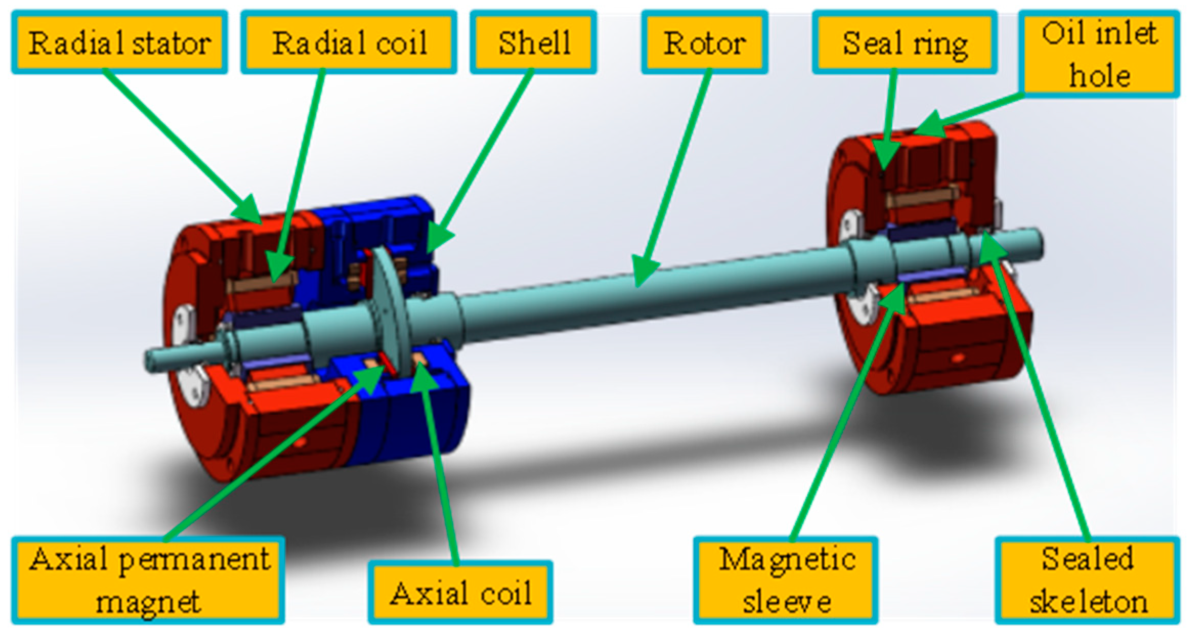
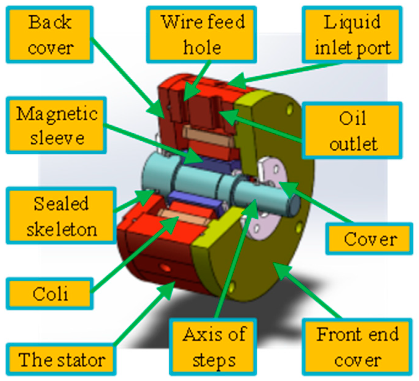
2. Magnetic Fluid Bearing System and Working Principle

The magnetic fluid bearing system studied in this paper includes the following components, mainly composed of radial electromagnetic composite bearing, axial permanent magnet composite bearing, control module, rotor component, sealing device and so on, as shown in Figure 1. As a new type of bearing, it combines the advantages of electromagnetic bearing and hydrostatic bearing. Hydrostatic system has the characteristics of small clearance, positive stiffness, and suspension by using repulsive force, while electromagnetic suspension system is the opposite. Magnetic fluid support is provided with axial support and radial support by electromagnetic force and static pressure, and the radial support can improve the bearing capacity and stiffness by adjusting the electromagnetic force and static pressure in real time according to a certain dynamic parameter.
When the system is started, hydraulic oil is first introduced into the support system through the pump station. The hydraulic oil enters the stator through the radial stator oil inlet and flows into the support cavity. At this time, the oil sealing surface of the stator and the magnetic guide sleeve of the rotor are connected with each other, and the hydraulic oil is blocked to form static pressure in the support cavity, which will play a supporting role on the rotor. The rotor realizes stable suspension under the action of static pressure. The oil sealing surface of the stator is separated from the magnetic guide sleeve of the rotor. There is a gap between them. The hydraulic oil in the support cavity flows into the return slot between the magnetic poles of the magnetic fluid bearing through the support end face. After cooling the coil, it flows back to the oil tank through the oil outlet. At this time, the stable support of the hydrostatic support system is realized. After the hydrostatic system works stably, each coil is energized to generate surrounding electromagnetic force and then electromagnetic force. At this time, the resultant force of the magnetic fluid support is the combined action of electromagnetic force and static pressure. The coil current of different magnetic poles can be adjusted by detecting the change, so as to achieve the balanced support of electromagnetic force and static pressure, and realize the stable and balanced operation of the bearing.
Two adjacent magnetic poles in the stator are wound around the coil to form a magnetic field after energization, which generates electromagnetic suction on the rotating shaft to ensure suspension. The oil of the hydrostatic system forms a liquid film through the inner hole of the magnetic pole to the contact surface between the magnetic pole and the shaft. The liquid film with a certain thickness is used as the hydrostatic bearing surface. When the system works, the change of the liquid film thickness changes the bearing capacity and stiffness of the bearing, and ensures the reliability of the system operation [13,14,15].
The radial magnetic fluid bearing is mainly studied. The radial magnetic fluid bearing is mainly composed of stator, rotor and hydraulic oil circuit. The stator material is treated with silicon steel and chromium plating, and the rotor is added with magnetic sleeve to increase magnetic conductivity. Other accessories include coil, end cap, cover and other components. The number of magnetic pole columns in the stator is 8, and the shape is columnar structure. The copper wire winding is wound on each magnetic pole column, and the winding mode is NSSNNSSN, so that two adjacent magnetic poles form a magnetic pole pair. When the bearing is working, the winding is energized, and the four magnetic poles move relative to the magnetic sleeve on the rotor to form a closed loop, and the stator magnetic pole generates electromagnetic attraction to the magnetic sleeve. The magnetic pole of the cylindrical structure is processed, and the liquid inlet hole is formed in the middle of the magnetic pole. The oil is pumped out from the oil tank, and the liquid film is formed through the liquid inlet hole to the end face between the magnetic pole and the magnetic sleeve to form the hydrostatic bearing cavity. The hydrostatic bearing force is formed under the condition of uninterrupted oil supply. The oil passes through a return tank between two magnetic poles to the oil outlet [16,17]. The structure of the radial magnetic fluid bearing is shown in Figure 2.

3. Mathematical Analysis of Bearing Capacity of Radial Magnetic Liquid Bearing

The stator material is silicon steel (23QG385), the rotor material is 316 stainless steel, and the outer layer of the rotor is added with a magnetic sleeve (cold rolled non-oriented silicon steel + chromium plating treatment). The initial working parameters of the magnetic fluid bearing are shown in Table 1.

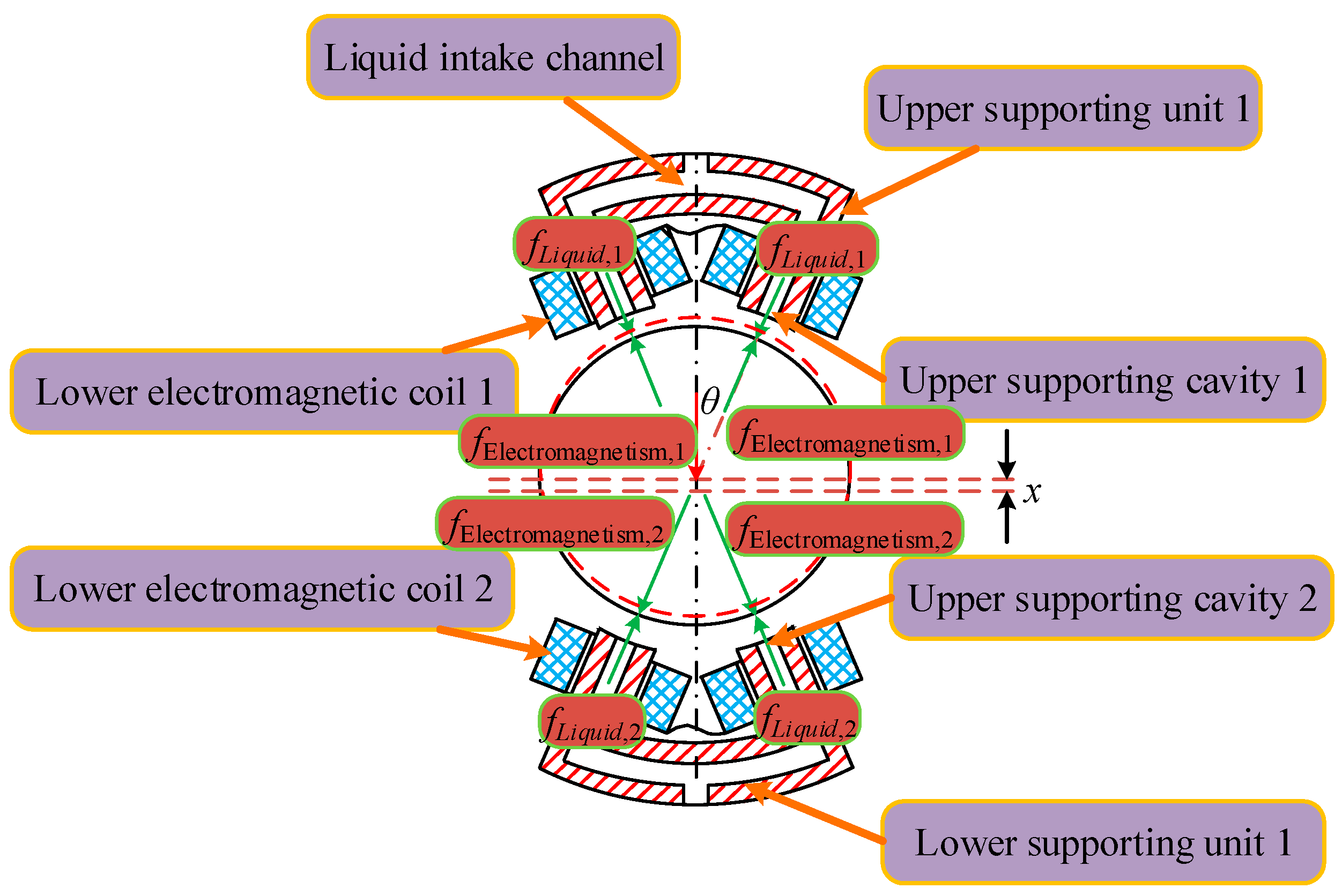
3.1. Force Analysis of Radial Magneto-Liquid Bearing

The magnetic fluid support system is mainly composed of electromagnetic support and hydrostatic support. The support form of the system combines the advantages of hydrostatic support and electromagnetic support to form a magnetic fluid dual support. The electromagnetic system responds quickly to the current regulation, while the static pressure bearing system responds slowly to the flow regulation. In addition, the static pressure bearing cavity has a small gap, and the required flow is small. The hydraulic oil will change due to the influence of external environment such as temperature, and it is difficult to achieve accurate control. Therefore, the system adopts the overall control method of constant flow oil supply, which regulates the current [18].
The magnetic fluid supporting system consists of eight magnetic poles and eight supporting cavities. Two adjacent magnetic poles and two adjacent supporting cavities and the rotor form a supporting unit. It is convenient for analysis and calculation. The magnetic fluid bearing is set as a single-degree-of-freedom system. The supporting mechanism is as follows: before the system starts, the rotor is in a static state, and the oil retained in the supporting cavity has a certain supporting effect to ensure that the rotor is in a lubricating state when starting. When it is in balanced operation after starting, the electromagnetic force and static pressure work together. The oil film thickness of each supporting unit is the same, and the input current and flow rate are the same. The supporting force of each supporting unit is equal, and the rotor is suspended at the midline position. If the external load is applied to the rotor, the rotor will shift to the relative direction, the oil film thickness between the rotor and the support unit becomes smaller, the static pressure repulsion increases, and the rotor is pushed to the center position. At the same time, the displacement sensor senses that the rotor is offset, and the displacement will be fed back to the control system. The control system regulates the current of each coil in real time, increases or decreases the electromagnetic support force, and pushes the rotor back to the center position together with the static pressure. Magnetic fluid bearing force diagram is shown in Figure 3.

3.2. Radial Support System Initial State Mathematical Model

According to the force of the magnetic fluid bearing system, a mathematical model is established. Ignoring some factors that have little influence on the bearing characteristics, the following assumptions are made for the magnetic fluid bearing system [19]:
  • Lubricating fluid is laminar flow state, ignoring the liquid inertia force;
  • Ignore the viscosity-pressure characteristics of liquid;
  • Ignore winding magnetic flux leakage;
  • The magnetic flux is evenly distributed in the magnetic circuit, all through the stator core, ignoring the hysteresis;
  • Calculated according to the single degree of freedom system.
According to Figure 3, the upper and lower support units contain two magnetic poles. The magnetic poles and the rotor have a certain deflection angle. The electromagnetic attraction of the upper and lower support units is equal to:
f Electromagnetism , 1 , 0 = f Electromagnetism , 2 , 0 = μ 0 N 2 A 0 i 0 2 2 χ 0 2 cos α
A0——Cross-sectional area of magnetic field air gap, m2;
μ0——Air permeability, H/m;
N——Number of coil turns, Zero dimension;
i0——Initial coil current, A;
x0——Air gap length between stator and rotor core, m;
α——Angle between center line of supporting cavity and center line of rotating shaft, °.
f Electromagnetism ——Electromagnetic attraction of support unit, N;
In the initial state, the rotor is at the center of the bearing system, the oil film thickness of the upper and lower support chambers is equal, the flow rate of each support chamber is equal, and the initial current of the electromagnetic coil is equal. According to the Navier-Stokes equation, the hydrostatic bearing force of the upper and lower support units can be obtained as follows:
{ f Liquid , 1 , 0 = 2 q 1 , 0 R 1 , 0 A e cos α f Liquid , 2 , 0 = 2 q 2 , 0 R 2 , 0 A e cos α
f L i q u i d ——Support unit hydrostatic bearing force, N;
p0——Support cavity pressure, Pa;
Ae——Bearing area of supporting cavity, m2;
α——Angle between center line of supporting cavity and center line of rotating shaft, °;
q0——Flow of supporting cavity, m3/s;
R0——Fluid resistance of supporting cavity, Pa·s/m3.
According to Figure 3 and Newton’s second law, ignoring the mass of the rotor, the mechanical balance equation of the rotor is obtained:
f Electromagnetism , 1 , 0 + f Liquid , 2 , 0 f Electromagnetism , 2 , 0 f Liquid , 1 , 0 = 0

3.3. Mechanical Model Construction of Radial Support System

Under the working state, the rotor is offset by the external load, and the displacement change of the rotor is Δ x . At this time, the liquid film thickness x1 and x2 of the upper and lower support cavities of the hydrostatic bearing system are:
{ x 1 = ( x d e ) + Δ x cos θ x 2 = ( x d e ) Δ x cos θ
de——Thickness of chromium plating layer of rotor, m.
The change of the liquid film thickness will cause the change of the flow rate of the supporting cavity. At this time, the flow rates of the upper and lower supporting cavities q1 and q2 are:
{ q 1 = q 0 A b x . 1 q 2 = q 0 A b x . 2
Ab——Extrusion area of supporting cavity, m2.
According to the Navier-Stokes equation, the hydrostatic bearing force of the oil cavity of the upper and lower support units is obtained as follows:
{ f Liquid , 1 = 2 q 1 R 1 A e cos α f Liquid , 2 = 2 q 2 R 2 A e cos α
f L i q u i d ——Support unit hydrostatic bearing force, N;
q——Input flow of supporting unit, L/min;
When the rotor is offset by the external load, the offset is fed back to the control system. The control system adjusts the coil current of the upper and lower poles to push the rotor to the equilibrium position. The PD control system is used to control the coil current through displacement feedback [20,21]. The control current model is:
i c = 150 ( K p Δ x + K d Δ y )
ic——Control current, A;
Kp——Proportional feedback coefficient of control system, Zero dimension;
Kd——Differential feedback coefficient of control system, Zero dimension;
Δ y ——Rotor vibration velocity, m/s.
According to Maxwell equation, the electromagnetic suspension supporting force of upper and lower poles is calculated by magnetic circuit method:
{ f Electromagnetism , 1 = 2 k cos α ( i 0 + i c ) 2 ( x + Δ x cos α ) 2 f Electromagnetism , 1 = 2 k cos α ( i 0 i c ) 2 ( x Δ x cos α ) 2
Similarly, according to Figure 3 and Newton’s second law, the mechanical equilibrium equation of the rotor is obtained:
f Electromagnetism , 1 + f Liquid , 2 f Electromagnetism , 2 f Liquid , 1 = m Δ x ..
m——Rotor quality, kg;
The dynamic equation of the magnetic fluid bearing can be obtained by the comprehensive solution (1)~(9):
m Δ x .. + f 1 ( Δ x , Δ x . ) + f 2 ( Δ x ) = 0
In the formula:
f 1 ( Δ χ . , Δ χ ) = [ δ 1 ( χ d e + Δ χ cos α ) 3 + δ 1 ( χ d e Δ χ cos α ) 3 ] Δ χ . ; f 2 ( Δ x ) = f 2 , 1 ( Δ x ) f 2 , 2 ( Δ x ) ; f 2 , 1 ( Δ x ) = δ 2 ( x + Δ x cos α ) 2 δ 3 ( x Δ x cos α ) 2 ; f 2 , 2 ( Δ x ) = δ 4 ( x d e + Δ x cos α ) 3 δ 4 ( x d e Δ x cos α ) 3 ; δ 1 = 2 μ A e A b cos 2 α B ; δ 2 = 2 k [ i 0 150 ( K p Δ x + K d Δ y ) ] 2 cos α ; δ 3 = 2 k [ i 0 + 150 ( K p Δ x + K d Δ y ) ] 2 cos α ; δ 4 = 2 μ q 0 A e cos α B

4. Weak Coupling Calculation of Bearing Characteristics of Radial Supporting System

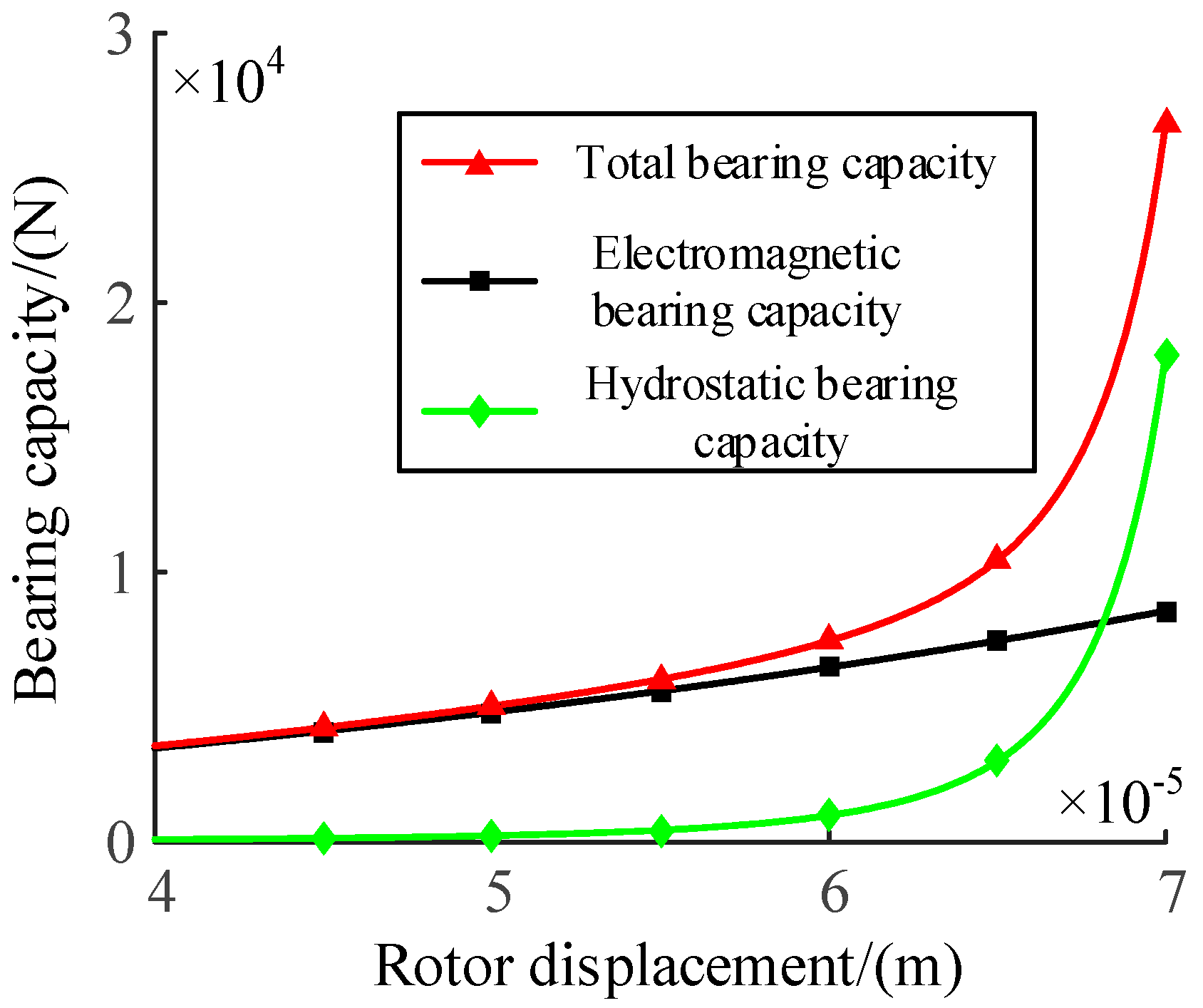
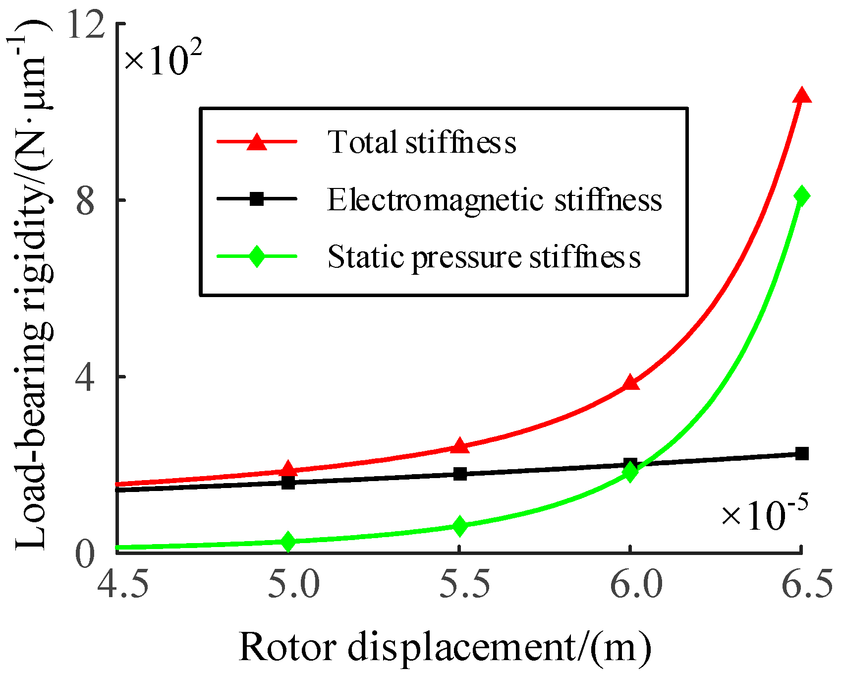
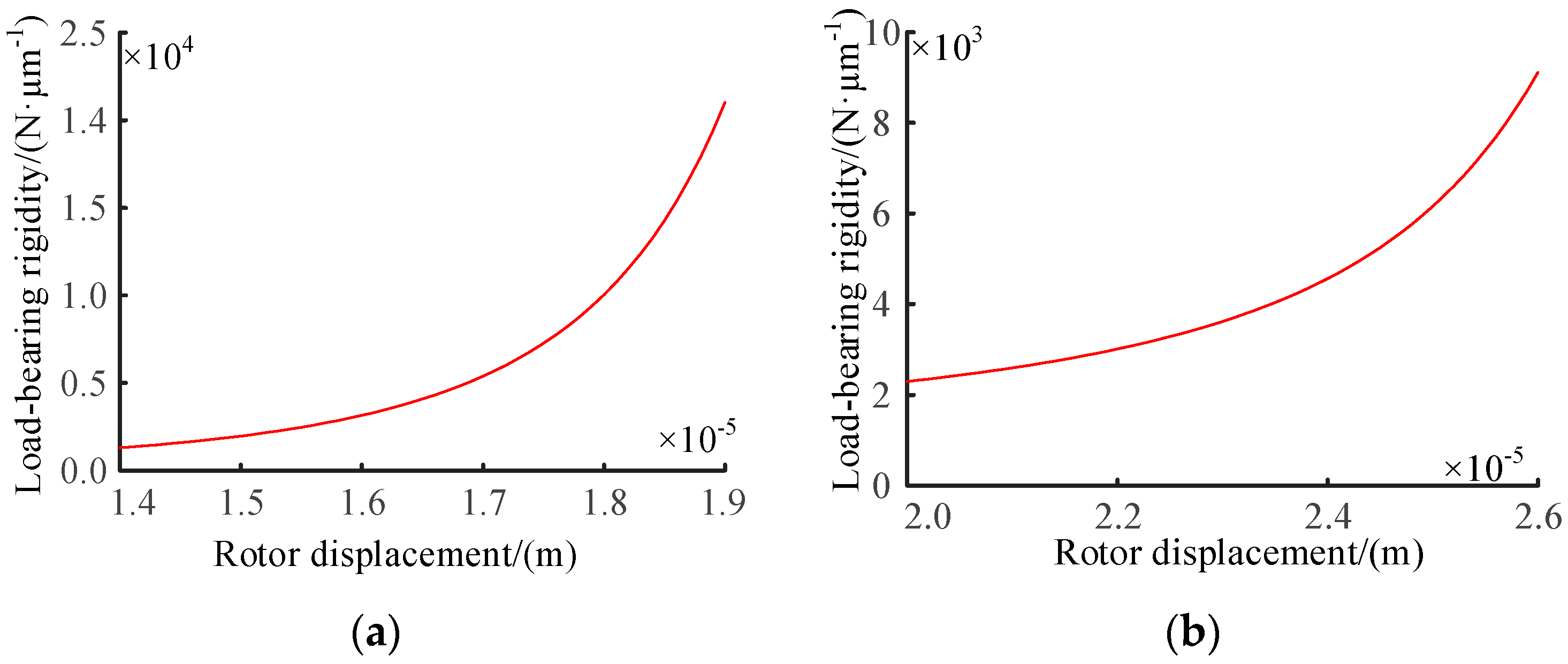
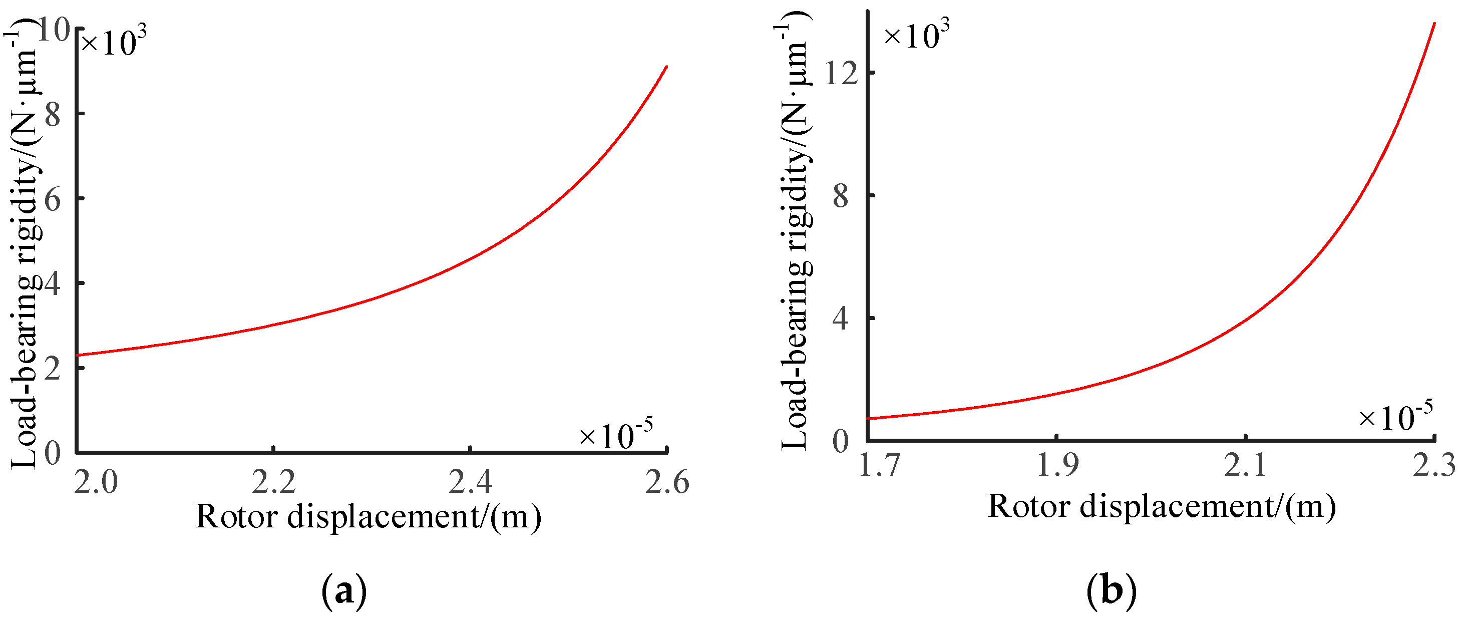
4.1. The Relationship of Bearing Force and Bearing Stiffness with Rotor Displacement

The initial electromagnetic force of a single supporting unit when the rotor is stationary at the rotation center is expressed as:
F Electromagnetism = 2 k i 0 cos θ x 2 = μ 0 N 2 A s i 0 2 cos θ 2 x 2
The supporting force of the electromagnetic system when the rotor is displaced is
F Electromagnetism , Resultant = μ 0 N 2 A s [ i 0 + 150 ( K p x + K d x . ) ] 2 cos θ 2 ( x + Δ x cos θ ) 2 μ 0 N 2 A s [ i 0 150 ( K p x + K d x . ) ] 2 cos θ 2 ( x Δ x cos θ ) 2
The static pressure expression of a single supporting unit when the rotor is stationary at the rotation center is
F Liquid = 2 q 0 μ A e cos θ B ( x d e ) 3
When the rotor displacement occurs, the static pressure system support force is
F Liquid , Resultant = 2 q 0 μ A e cos θ B ( x d e Δ x cos θ ) 3 2 q 0 μ A e cos θ B ( x d e + Δ x cos θ ) 3
It can be seen from Equations (12) and (14) that when the rotor is displaced, the total bearing capacity of the magnetic fluid bearing system is
F Resultant = 2 q 0 μ A e cos θ B ( x d e Δ x cos θ ) 3 2 q 0 μ A e cos θ B ( x d e + Δ x cos θ ) 3 + μ 0 N 2 A s [ i 0 + 150 ( K p x + K d x . ) ] 2 cos θ 2 ( x + Δ x cos θ ) 2 μ 0 N 2 A s [ i 0 150 ( K p x + K d x . ) ] 2 cos θ 2 ( x Δ x cos θ ) 2
Kp = −70, Kd = 0.03, x = 300 μm (including chromium coating de = 230 μm, oil film thickness = 70 μm), supporting cavity area Ae = 64 mm2, magnetic pole area As = 900 mm2, flow supporting coefficient B ¯ = 0.86, flow q0 = 5.61 × 10⁻⁷ m3/s. From Equations (12), (14) and (15), the relationship between the electromagnetic bearing force, the hydrostatic bearing force and the total bearing capacity with the rotor displacement, and the relationship between the bearing stiffness of the electromagnetic system, the bearing stiffness of the hydrostatic system and the total bearing stiffness with the rotor displacement are obtained [22,23]. This relationships are shown in Figure 4 and Figure 5.
As can be seen from Figure 4, the bearing capacity of electromagnetic support system and hydrostatic support system increases with the increase of rotor displacement. When the rotor displacement is small, the bearing capacity of electromagnetic support system and hydrostatic support system does not change significantly, and the bearing capacity of electromagnetic support system is greater than that of hydrostatic support system. When the rotor displacement is greater than 60 μm, the carrying capacity of hydrostatic bearing system will increase significantly, and when the rotor displacement is greater than 68 μm, the carrying capacity of hydrostatic bearing system will be greater than that of electromagnetic bearing system.
It can be seen from Figure 5 that the stiffness of the electromagnetic support system and the stiffness of the hydrostatic support system increase with the increase of the rotor displacement. The stiffness of the hydrostatic support system will change significantly, while the stiffness of the electromagnetic support system does not change significantly. When the rotor displacement is greater than 61 μm, the stiffness of the hydrostatic bearing system will exceed that of the electromagnetic bearing system. When the rotor displacement is greater than 61 μm, the system stiffness is mainly provided by the hydrostatic bearing system.

4.2. Influence of Key Parameters on Bearing Capacity and Rigidity

Adjust the structural parameters of the magnetic fluid bearing system, the side length of the support cavity and the thickness of the oil film, and analyze the changes of the operating parameters, current and rotor speed, to make the system reach the optimal state of bearing capacity and bearing stiffness.

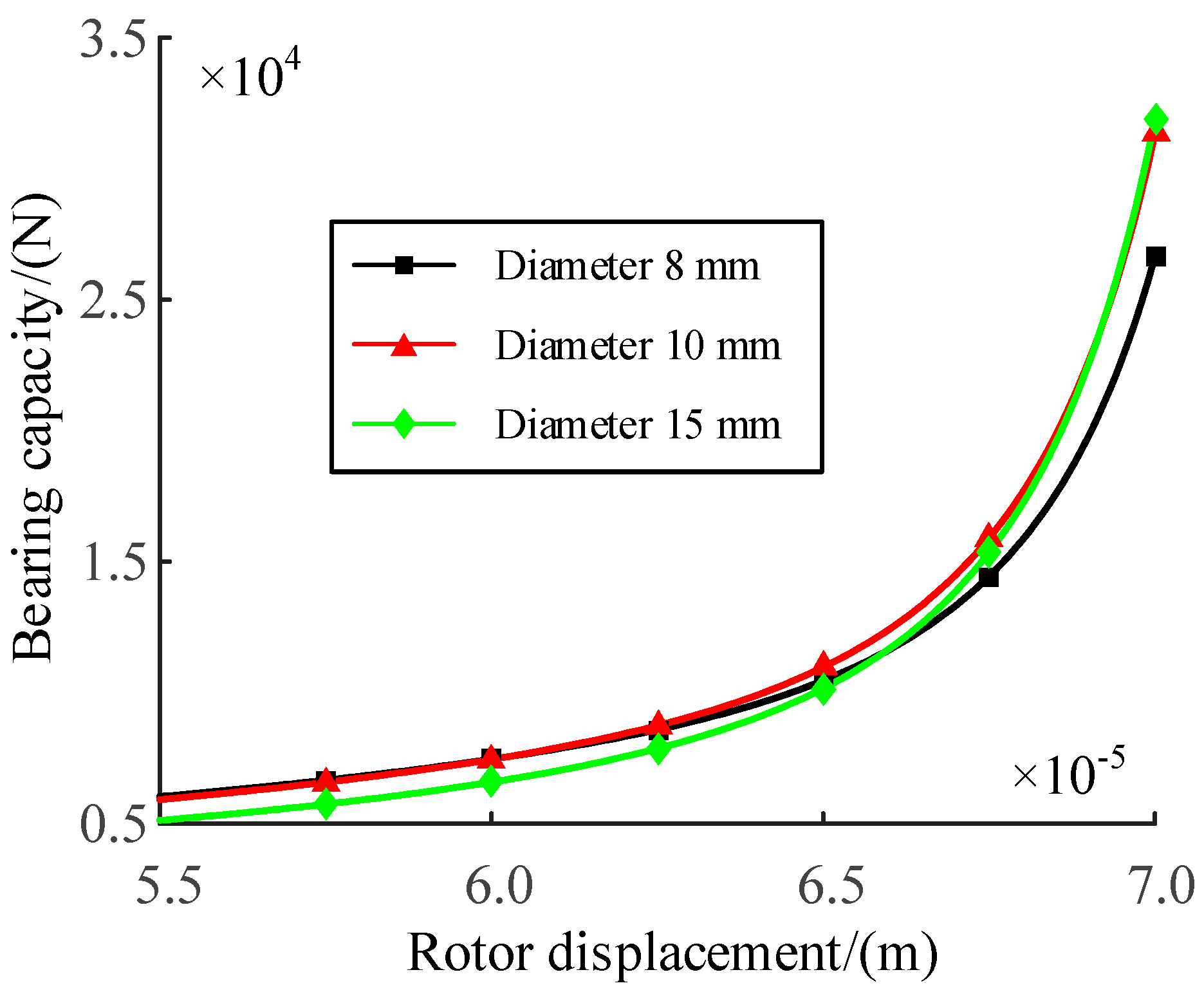
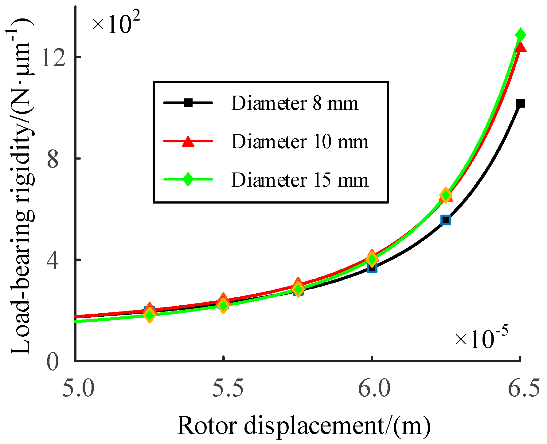
4.2.1. Influence of Bearing Cavity Diameter

The original supporting cavity is 8 mm circular. Considering the actual size of pole column, supporting cavity diameter can be selected 8 mm, 10 mm, 15 mm three sets of data for comparison. The curves of bearing capacity and stiffness of supporting system with displacement under different supporting cavity diameters are shown in Figure 6 and Figure 7.
It can be seen from Figure 6 that when the rotor displacement is less than 62.5 μm, the bearing capacity of the support cavity with a diameter of 15 mm is the smallest, and the bearing capacity of the support cavity with a diameter of 8 mm and 10 mm is almost the same. When the rotor displacement is between 62.5 μm and 66 μm, the bearing capacity of the support cavity with a diameter of 10 mm is the largest, followed by the diameter of 8 mm, and the bearing capacity of the diameter of 15 mm is the smallest. When the rotor displacement is greater than 66 μm, the bearing capacity of 8 mm diameter is the smallest.
It can be seen from Figure 7 that when the rotor displacement is less than 57 μm, the bearing stiffness of the support cavities with diameters of 8 mm, 10 mm and 15 mm is almost the same. When the rotor displacement is greater than 57 μm, the bearing stiffness of the support cavity with a diameter of 10 mm and 15 mm is almost the same, while the bearing stiffness of the support cavity with a diameter of 8 mm is the smallest.
It can be seen from the above that the bearing capacity and bearing stiffness have good performance under different rotor displacements, and the supporting cavity with a diameter of 10 mm has the best supporting performance.

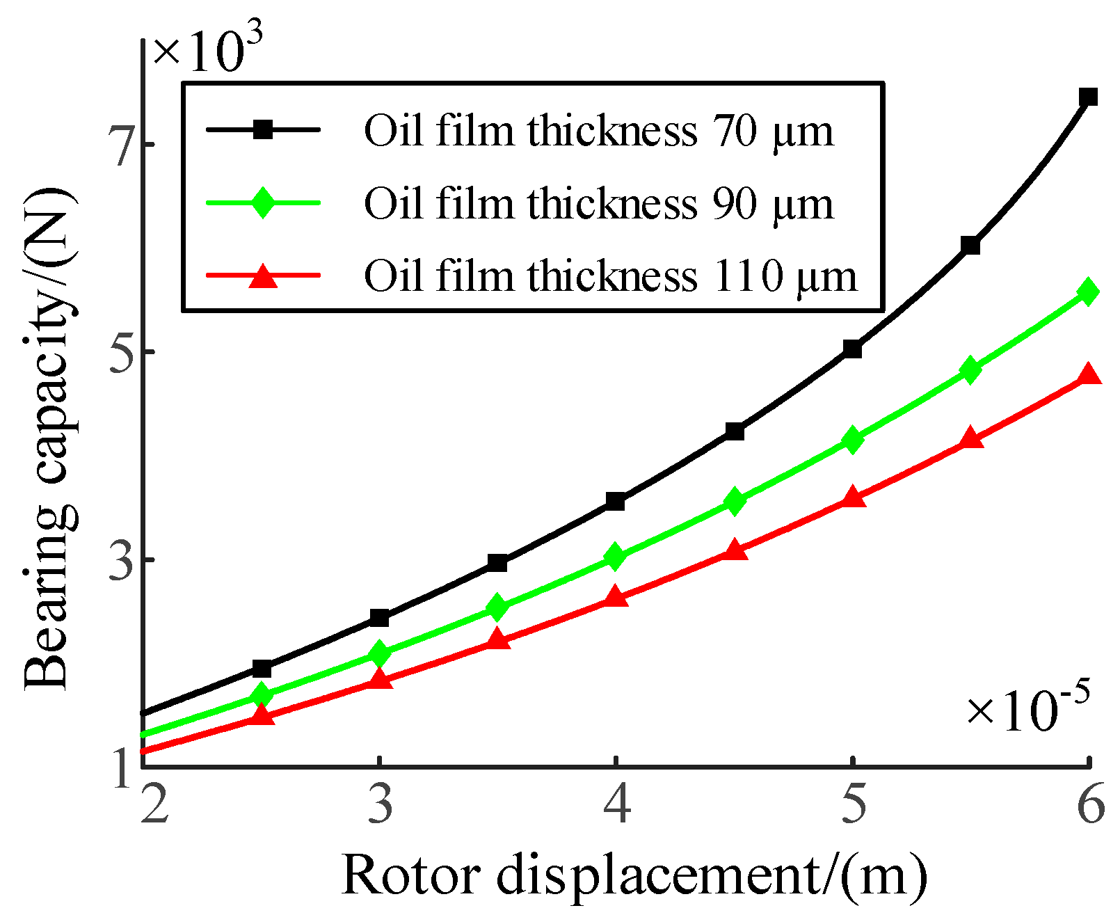
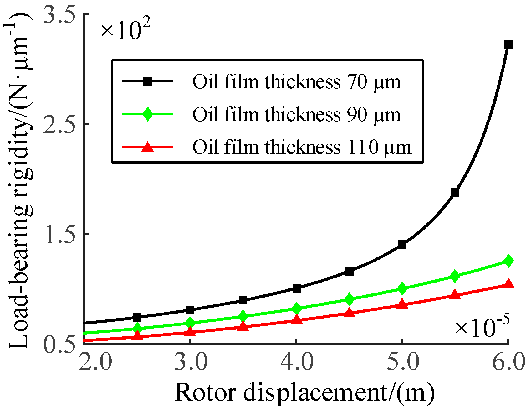
4.2.2. Influence of Oil Film Thickness

The initial oil film thickness is 70 μm. Oil film thickness selected 70 μm, 90 μm, 110 μm three sets of data comparison, bearing capacity and stiffness of the supporting system with displacement curves are shown in Figure 8 and Figure 9.
From Figure 8, it can be seen that the bearing capacity of the three oil film thicknesses increases with the increase of the rotor displacement. When the oil film thickness is 70 μm, the bearing capacity increases the most, while the bearing capacity increases slightly under the oil film thickness of 90 μm and 110 μm. And the bearing capacity under 70 μm oil film thickness is greater than that under 90 μm and 110 μm oil film thickness.
It can be seen from Figure 9 that the bearing stiffness of the three oil film thicknesses increases with the increase of the rotor displacement. When the oil film thickness is 70 μm, the bearing stiffness increases significantly, while the bearing stiffness under the oil film thickness of 90 μm and 110 μm does not change significantly with the rotor displacement. And the bearing stiffness under 70 μm oil film thickness is significantly greater than that under 90 μm and 110 μm oil film thickness.
It can be seen from the above that the bearing performance is the best when the oil film thickness is 70 μm, and it is superior to the other two in terms of bearing capacity and bearing stiffness.

4.2.3. Influence of Input Current

With the input current of 2.0 A as the benchmark and 0.2 A as the increment, the initial values of other operating parameters remain unchanged. As the input current increases from 2.0 A to 2.8 A, the oil film thickness decreased by 8.60 reaches 61.4 μm. The relationship between the total bearing stiffness and rotor displacement before and after the change of oil film thickness is shown in Figure 10.
Where Figure 10a is total stiffness of bearing system before oil film thickness change, Figure 10b is total stiffness of bearing system after oil film thickness change. It can be seen from Figure 11 that when the current gradually increases, the total thermal deformation of the bearing causes the displacement of the rotor to decrease, and the change trend of the total bearing stiffness with the displacement is basically unchanged, but the bearing stiffness is significantly increased.

4.2.4. Influence of Oil Inlet Flow

Set the initial flow rate as 0.02 L/min, take the oil inlet flow rate as 0.02 L/min, 0.03 L/min, 0.04 L/min, 0.05 L/min and 0.06 L/min in order, and analyze the effect of flow rate on stiffness. When the oil inlet flow is 0.02 L/min, the minimum oil film thickness is 65.8 μm. The relationship between bearing stiffness and rotor displacement before and after oil film thickness change is shown in Figure 11.
It can be seen from Figure 11 that with the increase of the flow rate, the thermal deformation gradually decreases, resulting in little change in the oil film thickness compared with the initial value, and little change in the rotor displacement. The change trend of the total bearing stiffness with the displacement change is basically unchanged, but the bearing stiffness slightly increases.
To sum up, the increase and change of the input current has a greater impact on the stiffness, and the increase of the flow has a smaller impact on the stiffness, but the trend of the total bearing stiffness increasing with the decrease of the rotor displacement is basically unchanged.

5. Conclusions

(1)
For the trunnion bearing, this paper proposes a new coupling support technology combining electromagnetic support and hydrostatic support-hydro-magnetic bearing, which can control electromagnetic and hydrostatic pressure in real time, and it is convenient to adjust the operation of tilting mechanism. It has the advantages of fast response speed and reducing the probability of dry friction.
(2)
The total bearing capacity and stiffness increase with the increase of rotor displacement. When the rotor displacement is less than 68 μm, the system bearing capacity is mainly provided by the electromagnetic support system. When the rotor displacement is greater than 68 μm, the system stiffness is mainly provided by the hydrostatic support system.
(3)
The supporting cavity with a diameter of 10 mm has the best supporting performance, and the bearing capacity increases significantly when the oil film thickness is 70 μm. Such size parameters are conducive to supporting the weight of furnace body, liquid metal, steel slag, suspension reducer and other equipment.

Author Contributions

Conceptualization, L.C. and B.C.; methodology, L.C. and J.Z.; software, X.W. and C.Y.; validation, L.C., B.C. and J.Z.; formal analysis, L.C. and X.W.; investigation, B.C. and C.Y.; resources, J.Z.; data curation, X.W. and C.Y.; writing—original draft preparation, L.C.; writing—review and editing, L.C.; visualization, B.C. and X.W.; supervision, J.Z. and C.Y.; project administration, L.C.; fundin acquisition, L.C. All authors have read and agreed to the published version of the manuscript.

Funding

This research was funded by the National Natural Science Foundation of China (No. 51705445; No. 52075468), Hebei Youth Fund Project (No. E2016203324), and Hebei Natural Science Foundation Project (No. E2020203052).

Institutional Review Board Statement

Not applicable.

Informed Consent Statement

Not applicable.

Data Availability Statement

Not applicable.

Acknowledgments

Thanks are given to the State Key Laboratory of Fluid Power and Electromechanical Systems for their help with training. Thanks are given to Yang Aimin for his guidance. In addition, thanks are given to the authors’ colleagues for their companionship.

Conflicts of Interest

The authors declare no conflict of interest.

References

  1. Tian, J.; Wang, Y.; Zhao, H. Geometrical Design for a Large Magnetic Supporting System Considering Physics Coupling. Mach. Tool Hydraulics 2007, 35, 16–18. [Google Scholar]
  2. Qiu, J. Study on Spindle Dynamic Errors of Domestic NC Machine Tools. Adv. Mater. Res. 2013, 690–693, 3279–3283. [Google Scholar] [CrossRef]
  3. Qu, C.N.; Wu, L.S.; Xiao, Y.C.; Zhang, S. Summary of guideway technology research on machine tools. Manuf. Technol. Mach. Tool 2012, 594, 30–36. [Google Scholar]
  4. Xiong, W.L.; Sun, W.; Liu, K.; Xu, M.; Pei, T. Active Magnetic Bearing Technology Development in High-Speed Motorized Spindles. J. Mech. Eng. 2021, 57, 1–17. [Google Scholar]
  5. Wang, X.H.; Yang, F.F.; Zhao, Q. Dynamic Analysis of the Aero-engine Rotor Drop after the Failure of Active Magnetic Bearings. Gas Turbine Exp. Res. 2019, 32, 1–7. [Google Scholar]
  6. Li, H.; Shuai, C.G.; Xu, W. Research on the Axial Bearing Capacity of Marine Permanent Magnetic Thrust Bearing. Ship Sci. Technol. 2019, 41, 105–109. [Google Scholar]
  7. Zhang, J.; Zhang, F.; Zhu, Z.D.; Bai, W. Analysis of Gas Flow Field Characteristics Based on CFX Air Magnetic Suspension Bearing. Mech. Eng. Autom. 2019, 6, 57–59+62. [Google Scholar]
  8. Li, W.J.; Zhang, G.M.; Wang, X.W.; Qiu, Q. Design of Superconducting Electromagnetic Hybrid Magnetic Suspension Bearing for Flywheel Energy Storage System. Trans. China Electrotech. Soc. 2020, 35, 10–18. [Google Scholar]
  9. Yan, G.; Yuan, X.Y.; Chen, R.L.; Jia, Q.; Jin, Y. Structure Design and Performance Analysis of Superconducting Magnetic-Liquid Thrust Bearings. China Mech. Eng. 2021, 32, 32–39. [Google Scholar]
  10. He, T.; Wang, J.; Yao, S.; Shi, J.; Zhang, Q.; Xu, H.; Zhao, B. Study on Dynamics and Tribological Properties of Composite Water-lubricated Bearing with Magnetic Support. J. Propuls. Technol. 2022, 43, 200401. [Google Scholar]
  11. Lu, Q.Q.; Li, M.; Yang, J.H.; Xu, J.W.; Hu, J. Fault Diagnosis for Converter Trunnion Bearings Based on Acoustic Emission Testing Technology. Bearing 2013, 1, 46–50. [Google Scholar]
  12. Cheng, X.W.; Qi, L.Y. Nonlinear Dynamic Analysis of Converter Tilting Mechanism Based on Bond Graph. Mech. Eng. Autom. 2017, 4, 28–30. [Google Scholar]
  13. Zhao, J.H.; Zhang, B.; Chen, T.; Wang, Q.; Gao, D. Influence of Liquid Film Thickness on Bearing Characteristics of Magnetic-Liquid Suspension Guide-Way. J. Eng. 2019, 13, 293–298. [Google Scholar] [CrossRef]
  14. Chen, L.W.; Gao, D.R.; Zhao, J.H.; Zhao, J. Study on Temperature Rise and Thermal Deformation of Rotor Caused by Eddy Current Loss of Magnetic-Liquid Double Suspension Bearing. Int. J. Model. Identif. Control. 2021, 37, 267–274. [Google Scholar] [CrossRef]
  15. Du, X.X.; Sun, Y.H. Comparison of Static and Dynamic Characteristics of Electromagnetic Bearing Using Machine Learning Algorithm. Int. J. Grid Util. Comput. 2022, 13, 87–95. [Google Scholar] [CrossRef]
  16. Weng, G.; Tian, X.; Zhao, J.; Zhang, B.; Wang, Q.; Chen, T.; Liu, J.; Gao, D. Determinate Mathematical Model of Couple Bearing Force of Magnetic-Liquid Suspension Guide-Way with Complicate Constraint. High Technol. Lett. 2018, 24, 440–448. [Google Scholar]
  17. Chen, L.W.; Gao, D.R.; Zhao, J.H.; Zhao, J. Study on The Law of The Structure Parameters Influence on Thermal Deformation of Magnetic Poles of Magnetic-Liquid Double Suspension Bearing. Int. J. Comput. Appl. Technol. 2022, 69, 253–262. [Google Scholar] [CrossRef]
  18. Yu, L. Controllable Magnetic Suspension Rotor System; Science Press: Beijing, China, 2003; pp. 108–233. [Google Scholar]
  19. Song, H.Q. Engineering Fluid Mechanics; Metallurgical Industry Press: Beijing, China, 2018; pp. 21–99. [Google Scholar]
  20. Wu, X.C. Research on Static Bifurcation and Hopf Bifurcation of Magnetic Fluid Double Suspension Bearing. Master’s Thesis, Yanshan University, Qinhuangdao, China, 2020. [Google Scholar]
  21. Ono, S.; Uchikoshi, T.; Hayashi, Y.; Kitagawa, Y.; Yeh, G.; Yamaguchi, E.; Tanabe, K. A Heterothermic Kinetic Model of Hydrogen Absorption in Metals with Subsurface Transport. Metals 2019, 9, 1131. [Google Scholar] [CrossRef] [Green Version]
  22. Wang, J.; Zhao, G.S.; Song, Y.B. MATLAB Modeling and Simulation Practical Tutorial; China Machine Press: Beijing, China, 2018; pp. 161–231. [Google Scholar]
  23. Wang, X.; Rui, X. Dynamics modeling and simulation of tracked armored vehicle with planar clearance trunnion-bearing revolute joint. J. Mech. Sci. Technol. 2021, 35, 2285–2302. [Google Scholar] [CrossRef]
Figure 1. Magnetic fluid bearing system.
Metals 13 00549 g001
Figure 2. Magnetic fluid bearing semi-section equiaxial side diagram.
Metals 13 00549 g002
Figure 3. The force diagram of single degree of freedom radial magnetic bearing.
Metals 13 00549 g003
Figure 4. Relation curve between bearing capacity and displacement Δx.
Metals 13 00549 g004
Figure 5. Relation curve between bearing stiffness and displacement Δx.
Metals 13 00549 g005
Figure 6. Curves of bearing capacity and rotor displacement system under different bearing cavity diameters.
Metals 13 00549 g006
Figure 7. Curves of bearing stiffness and rotor displacement system under different bearing cavity diameters.
Metals 13 00549 g007
Figure 8. Relationship curve between bearing capacity and rotor displacement under different oil film thickness.
Metals 13 00549 g008
Figure 9. Relation curve between bearing stiffness and rotor displacement under different oil film thickness.
Metals 13 00549 g009
Figure 10. Stiffness-displacement curve. (a) is total stiffness of bearing system before oil film thickness change, (b) is total stiffness of bearing system after oil film thickness change.
Metals 13 00549 g010
Figure 11. Stiffness-displacement curve. (a) is total stiffness of bearing system before oil film thickness change, (b) is total stiffness of bearing system after oil film thickness change.
Metals 13 00549 g011
Table 1. Initial working parameters of magneto-liquid bearing.
Initial Current
i0/A
Initial Oil Inlet Pressure
p0/MPa
Initial
Rotation Speed
n/r·min−1
Oil Temperature
T/°C
Oil Film Thickness
μm
215002070
Disclaimer/Publisher’s Note: The statements, opinions and data contained in all publications are solely those of the individual author(s) and contributor(s) and not of MDPI and/or the editor(s). MDPI and/or the editor(s) disclaim responsibility for any injury to people or property resulting from any ideas, methods, instructions or products referred to in the content.

