Article

Process Technology for Diffusion Welding with Cyclically Pulsative Joining Forces

1
Chair of Welding Engineering, Department of Mechanical Engineering, Chemnitz University of Technology, 09126 Chemnitz, Germany
2
SincoTec Test Systems GmbH, 38678 Clausthal-Zellerfeld, Germany
*
Authors to whom correspondence should be addressed.
Metals 2023, 13(3), 547; https://doi.org/10.3390/met13030547
Submission received: 31 January 2023 / Revised: 1 March 2023 / Accepted: 6 March 2023 / Published: 8 March 2023
(This article belongs to the Special Issue Advances in Technology and Applications of Diffusion Bonding)

Abstract

:
Diffusion welding is a solid-state welding process and is characterised by the process parameters temperature, compression force and process time. Usually, the process force is applied as static load, and high demands with respect to specimen surfaces (low roughness, cleanliness) are common. The aim of this work was to improve the necessary technology for diffusion welding and, above all, to increase the quality of the joints by using cyclically pulsative joining forces to minimise the time or surface-specific conditions, which are typical for this process. For this purpose, a corresponding system technology had to be designed and manufactured. The basis of the system was a modified machine concept for materials testing. As a result, the modified system and the modified process were able to reduce the process time by a factor of 5 to 6 compared to the conventional joining time.

1. Introduction

In contrast to other joining processes, the formation of the joint during diffusion welding takes place in the solid phase of the workpieces. This means that there is no negative influence on the function of components or the properties of the materials. Diffusion welding is suitable, within specific technical and material limits, for joining any combination of materials of the same or different types.
Thus, this process has a certain charm that also holds great potential for future-oriented applications, especially for e-mobility, e.g., the joining of dissimilar materials such as copper with aluminium or a simultaneous joining of multi-layer component structures. Connections between up to 400 foil layers and more are possible within one joining process. With such manufacturing requirements, other processes such as laser joining reach their limits. Especially with regard to the necessary clamping force, which is required during the process and must be applied evenly and, above all, at a small distance from the joining point in order to avoid waves and uncontrolled welding through. These errors can be almost completely reduced by a two-dimensional joining process such as diffusion welding. On the other hand, the diffusion welding process offers the possibility of making the most diverse material combinations usable for various applications—material combinations that can hardly be realised with classic joining processes. For example, joints between aluminium and steel, aluminium and copper or steel and ceramics can only be joined very well with a process that works below the melting temperature (Ts) of the materials.
However, the complex surface preparation of the joining partners and the long joining times have a disadvantage in this context with diffusion welding. Joining times of several minutes, hours or even days are not uncommon. Comparatively high process costs with regard to an economic consideration of the joining process are the result.
Such points can be counteracted by adapting the design. On one hand, this refers to the design of the components to be joined, but also to the adaptation of the system technology. The latter was the subject of the R & D project (This research was funded by the Federal Ministry for Economic Affairs and Climate [ZIM research project ZF4012633FH9] based on a resolution of the German Bundestag) which, in cooperation with SincoTec Test Systems GmbH, provided for the development of a new type of joining and testing system for the diffusion welding process.
Within the project, an existing system technology was modified and further developed in such a way that it makes it possible to noticeably reduce joining time or the technical effort required for surface preparation. The basis for this is the use of dynamically applying the joining forces in the swelling range.

2. State of the Art

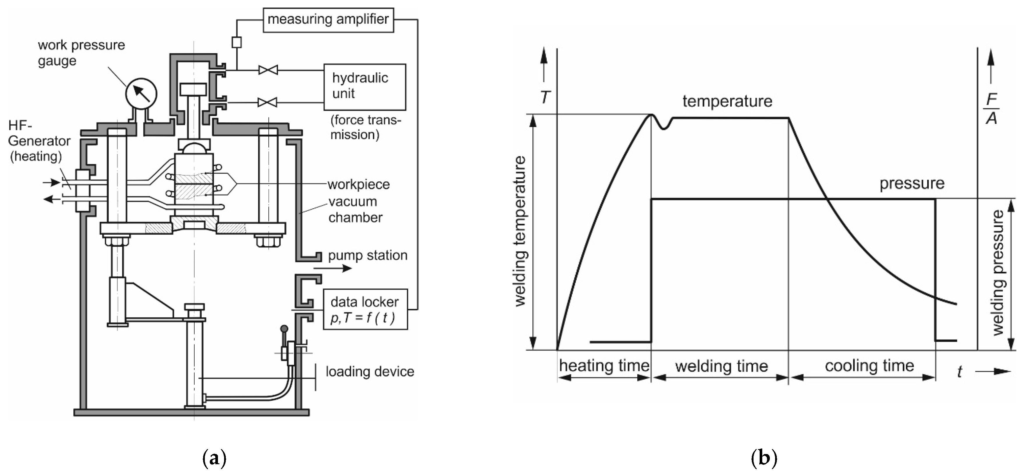
2.1. Fundamentals of Diffusion Welding

The joining of different metallic or ceramic materials is becoming more and more important in joining technology applications. In view of e-mobility and the provision of storage media of various types (lithium-ion accumulators, fuel cells, etc.) especially, welding is once again gaining in importance. However, there is the problem that when various materials are mixed by welding, there are always imperfections (inclusions, intermetallic phases, no feasible connection, etc.). This happens both as a result of the use of classic arc processes or under the use of beam processes such as laser welding or electron beam welding. The view of joining technology is thus turning in the direction of special welding processes, which were previously used for special applications and are now becoming interesting for a broader range of joining tasks. This also applies to diffusion welding, the process principle of which is welding in a solid state. The bond is created by diffusion with low contact pressures and deformations at temperatures above the recrystallisation temperature [1].
The actual joining process takes place through the naturally occurring physical process of equalising concentration differences between the workpieces to be joined [2]. This process, which takes place without any external influences, takes place due to Brownian motion. Over a specific period of time, creep processes take place in the abutting surface geometry of the joining partners due to the effects of force and temperature, a convergence in the range of atomic distances is the result, whereby there is an exchange or a change of place of individual atoms of the respective joining partners across the abutting edge and thus a bonding level/new structure is created. This takes place mainly through the application of force or pressure and heat as well as through an adjustment of the ambient atmosphere—realised in corresponding pressure chambers (recipients)—over a specific period of time. Figure 1 shows the principle of diffusion joining.
Thus, pressure, time, temperature and the specific atmospheric environment are the relevant main parameters of diffusion bonding, which enable the joining partners to be connected below the solidus line or the eutectic point [3]. Their exact compliance guarantees a high repeatability of the joining results.
A well-chosen process temperature promotes the diffusion processes in the materials to be joined, but is directly dependent on the materials to be joined [4]. Thus, welding temperatures that are too high bear the risk of poorer corrosion resistance or a deterioration of other mechanical–technological properties as a result of microstructural changes (e.g., altered grain growth). The precipitation of alloying elements in specific temperature ranges also plays a decisive role in this context, which can also influence the mechanical–technical properties of the final joints. For example, the welding temperature must be below the melting temperature (Ts) of the lowest melting joining partner. Depending on the material used, it is usually between 0.52 × Ts and 0.88 × Ts [1,2,5]. This determines the subsequent strength of the joint.
Parallel to this, the welding pressure creates a contact between the joining surfaces, whereby this should be even. In the course of this, the preparation of the component and the surface plays a decisive role for the successful realisation of such joints. Thus, with regard to plane-parallelism, evenness and cleanliness (removal of foreign layers or foreign substances), very good preparation of the joining surfaces is required, since, for example, the number and size of pores occurring in the joints are directly dependent on the surface roughness [4,6]. The surfaces to be joined must therefore be metallically bright by means of appropriate mechanical processing steps, such as grinding, polishing, lapping, etc. The average roughness (Ra) (Based on Geometrical product specifications [GPS]—Surface texture: Profile—Part 2: Terms, definitions and surface texture parameters [ISO 21920-2:2021, Corrected version 2022-06] [7]) should not be greater than 0.5 µm to 1.5 μm for metals, as well as glasses or ceramics.
Pressure and temperature are mutually dependent—the higher the static pressure, the lower the temperature must/can be selected [8,9]. The aim is to avoid excessive plastic deformation of the components. Special attention must also be paid to the component geometry and its possibly limited pressure resistance as a result of complex or filigree component structures. Therefore, contour-identical, self-centring and, above all, parallel joining surfaces are to be aimed for within the design of the components to be joined for this process, with the aim of ensuring an even distribution of pressure.
Subsequently, the joining partners or components are placed systematically and layered in a pressing device. In addition to the demanding surface properties, precise handling and layering must take place. The recipient is then evacuated, either to a predefined vacuum, usually around 10−6 mbar (0.1 Pa), or there may also be the option of flooding the recipient with protective gas (often argon, nitrogen or helium) after a specific vacuum has been reached. The specific atmospheres created in this way prevent the formation of new oxide layers. Here the residual oxygen content of the oven chamber should be less than 5 ppm [10].
Furthermore, the required process times must also be kept in mind. In addition to the formation of the joint, these also include the positioning of the materials to be joined in relation to each other, the realisation of the atmospheric bonds as well as the required temperature, divided into heating, holding and cooling times, and the application of the required joining force/pressure and depend on the type of system, the type of atmosphere and the materials to be added. The corresponding schematic process is shown in Figure 1b and, depending on the design, can take several minutes, hours or even days. However, it can be positively changed by modifying the other main parameters.
Under these conditions, it is possible to join metallic materials of the same type, but also dissimilar metallic materials, directly or via intermediate layers [2,8,11,12,13]. Basically, this process can be used to weld almost all “other materials and a large number of material combinations [...]” [1], i.e., also ceramics, glasses and/or components produced by powder metallurgy. However, the parameters to be set for time, pressure and temperature are only based on empirical values.

2.2. Recipient Design

In addition to the force (pressure)/time and temperature components for the joining process, diffusion welding also uses the advantages of a change in atmospheric conditions. Specifically, the joining process usually takes place under vacuum conditions and thus brings with it explicit requirements for the welding chamber necessary for this. These chambers or systems, also called recipients, are in themselves very complex technical structures—see Figure 2. An essential point in the context of their technical design is the physical size [14]. It seems to make sense to design the size of the recipient in relation to the size of the subsequent component.
In addition to the generation of a high vacuum (10−3 mbar ≤ p ≤ 10−8 mbar) inside the recipient, the generation or application of force through it must also be realised. First and foremost, attention must be paid to the method of force application/introduction. This would be possible in two ways statically and dynamically. Hydraulic, pneumatic, electrical and mechanical modes of action are mentioned here as examples to provide the forces [15]. The force-generating modules can either be installed inside the recipient—this requires a corresponding size of the chamber—or the force application is realised from outside and transferred to the inside of the recipient via corresponding cylinders. In this variant, the recipient can be made much more compact, whereby the sealing of the chamber interior against the outside atmosphere via the cylinders is of enormous importance. This means that the recipient must be hermetically sealed, but at the same time it must also allow the cylinders to move in order to create the necessary process conditions.
In parallel, the welding process requires a certain amount of heat energy to realise the specific joining temperatures. This is achieved either via thermal radiation or via induction—here, too, the respective systems are also integrated into the chambers and adjusted via the system control.
With regard to the weldability of components, a property of components/workpieces is that they can be joined together under given material, design and manufacturing conditions in such a way that the required service properties are fulfilled [16]. Thus, it can be seen that the modifications of the process can also necessitate changes within the design or the materials used. Or the other way around, if an improved welding result is to be achieved in diffusion welding with certain materials, the design can or must be modified.
On the one hand, this refers to the design of the components to be joined, but also to the adaptation of the system technology. The latter is the subject of this R & D project, which provided the development of a new type of joining and testing system for the diffusion welding process in cooperation with SincoTec Test Systems GmbH.

2.3. Conclusions from the State of the Art and Objectives

The use of joining processes is always in relation to the materials to be added and the respective joining design, namely, the arrangement of the components to each other. However, the temporal consideration also plays a role in the industrial view of the use of different processes that should not be underestimated. This is where the challenge of diffusion welding lies. If it is possible to link the welding time to specific quality criteria of the joining process and thus to reduce it noticeably, this makes it possible to improve the economic benefit and thus to increase the use of this joining process. In order to realise this, two relevant modifications have to be made to the system technology used to date.
On one hand, the component heating should take place independently of the atmosphere by induction and thus reduce the time requirement more strongly. In addition, there is the idea of using a frequency-superimposed pressure force generation, whereby either the requirements for the surface preparation of the components can be reduced, with constant welding temperatures and welding times, or, on the other hand, the process time can be considerably reduced by the forced joining surface approach due to the frequency-superimposed pressure force application.
This idea of using a controlled frequency superposition of the threshold force application in diffusion welding leads to three expected results:
  • Reduction of the machining effort of joining the surfaces in advance.
Plastic deformations in the pressure threshold range are thus forced and surface unevenness is better compensated. This facilitates an atomic approximation of the joining surfaces and reduces the stress on the material. As a result, either the joining pressure, the joining temperature and/or the joining time can be noticeably reduced.
2.
Reduction of the welding time up to the replacement of the welding time by a frequency-based test criterion.
At the same time, the modified plant system is put in a position to monitor and ideally also to qualify the joining characteristics, and consequently also to control them. The basis here is the assumption that the natural frequency and the amount of energy for applying the joining force and thus the stiffness of the system changes with increasing connection area. This can be detected and documented using adequate measurement technology, such as that developed by SincoTec Test Systems GmbH and used in its systems. From this, a quality criterion can be described with regard to the joining surface.
3.
Adjustment of more favourable material properties through the frequency-superimposed application of force, and reduction of the phase thicknesses.
At the same time, the parameter joining time should be related to the real joining characteristic that is formed and not to empirical values. On the one hand, this reduces the reject rate (as a result of the joining time being too short and the associated incomplete or insufficient bonding), on the other hand, the joining time can be shortened, as the joining process can be completed after the connection is complete.
Thus, the machine concept envisaged in the research project has the following novel characteristic features:
  • Testing of materials and compounds in reactive environments through inert atmosphere or vacuum;
  • Material and component testing under operating conditions, including temperature up to approx. 1000 °C, mechanical load in the compression and tensile range (static and dynamic), various inert ambient media;
  • Reduction of the required measures for joining surface preparation by facilitated approximation of the surfaces to each other on an atomic level;
  • Joining of materials in the pressure threshold range (welding pressure) up to 100 kN at characteristic frequencies up to 150 Hz and a variable number of load cycles;
  • Enhancement of the factor frequency shift or frequency monitoring for non-destructive characterisation of the welded joint during the joining process and qualification of a joining time adapted to the process condition.
These advantages, which can be expected through the modification of the system technology, will significantly increase the economic efficiency of diffusion bonding, which will open up new areas of application and innovations, e.g., in the field of fuel cell production, in the design of catalytic converters or heat exchangers.

3. Experimental Methods

3.1. Concept of Technical Implementation
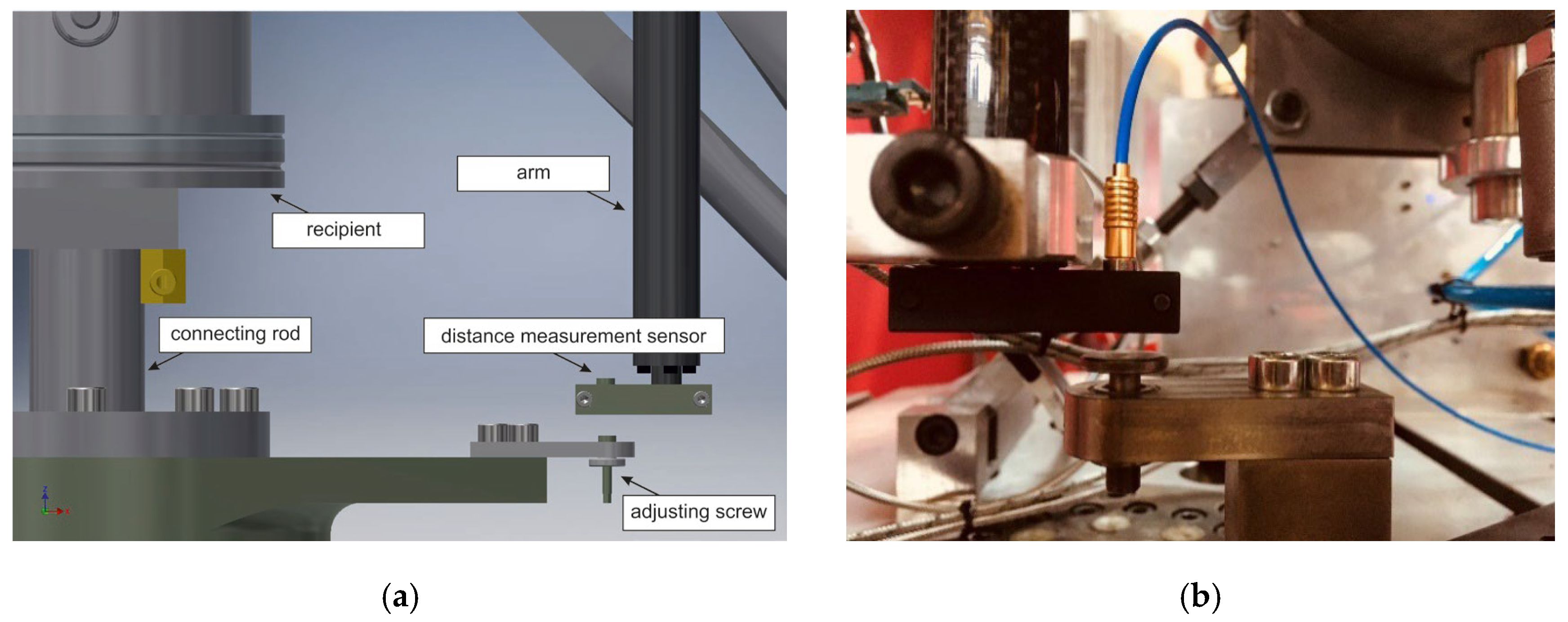
The aim of the project was to integrate a new type of process chamber for diffusion welding into an existing test and measurement system. The main focus of the project was therefore on the conception of different possibilities for implementing the specifications, the constructive design of the system components of a selected solution approach and ensuring the smooth interaction of the components with each other. The final step was the technical production implementation and testing of the system under the selected specifications. The basis for this was comprehensive research on the topic of diffusion welding and the process technology required for this. Based on this, a comprehensive specification sheet for the process chamber and its integration into the existing plant technology was drawn up.
The specifications were compiled and completed in accordance with the classification. It contains sections that deal only with the subject area of plant technology and the software options used, as well as sections that deal with the process technology side of the project (structure of the process chamber, control of the vacuum, design of the inductor, etc.). Any interfaces that arose were designed/adapted bilaterally.
The technical basis for this project, and thus for the improvement of diffusion bonding is the Power Swing type testing machine by SincoTec Test Systems GmbH (Clausthal-Zellerfeld, Germany); a motorised resonance testing machine for carrying out tensile/compression, bending and torsional vibration strength tests.

3.2. Construction

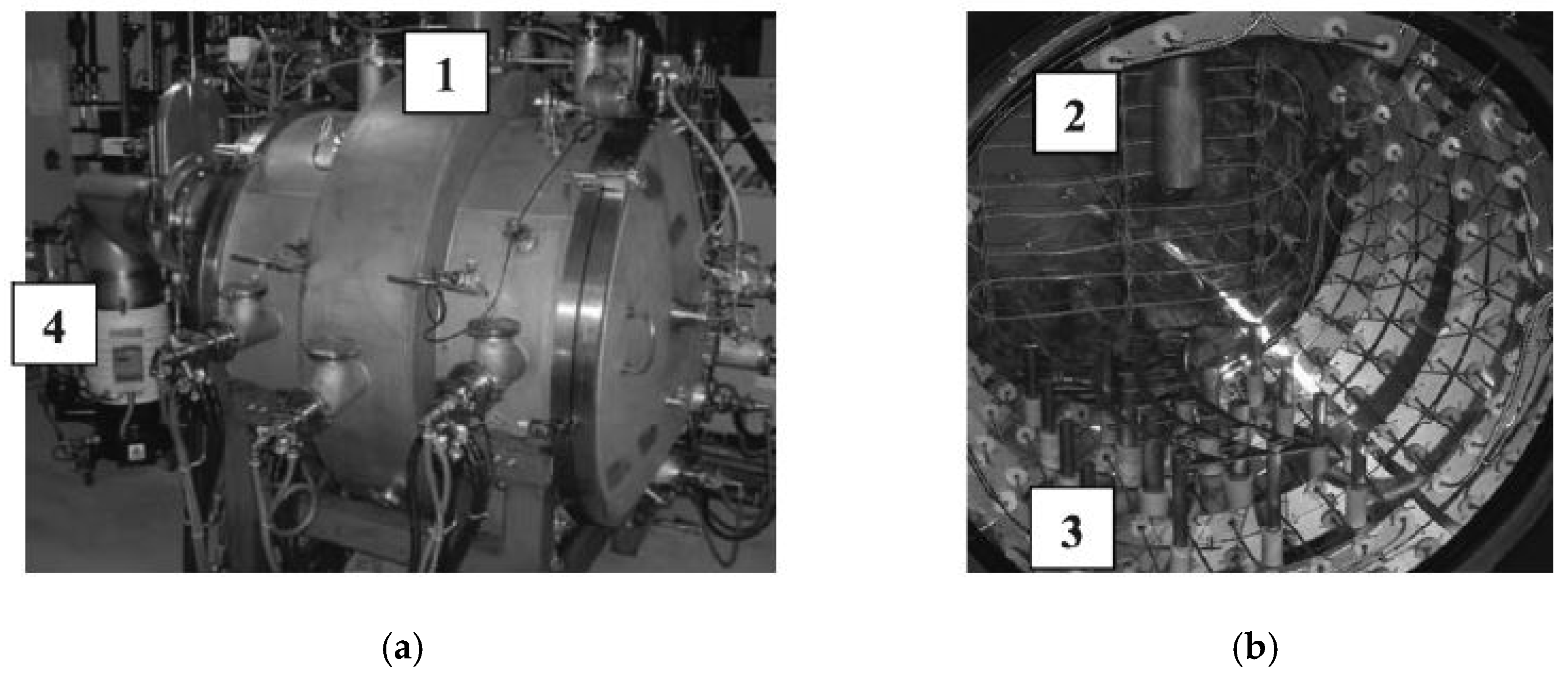
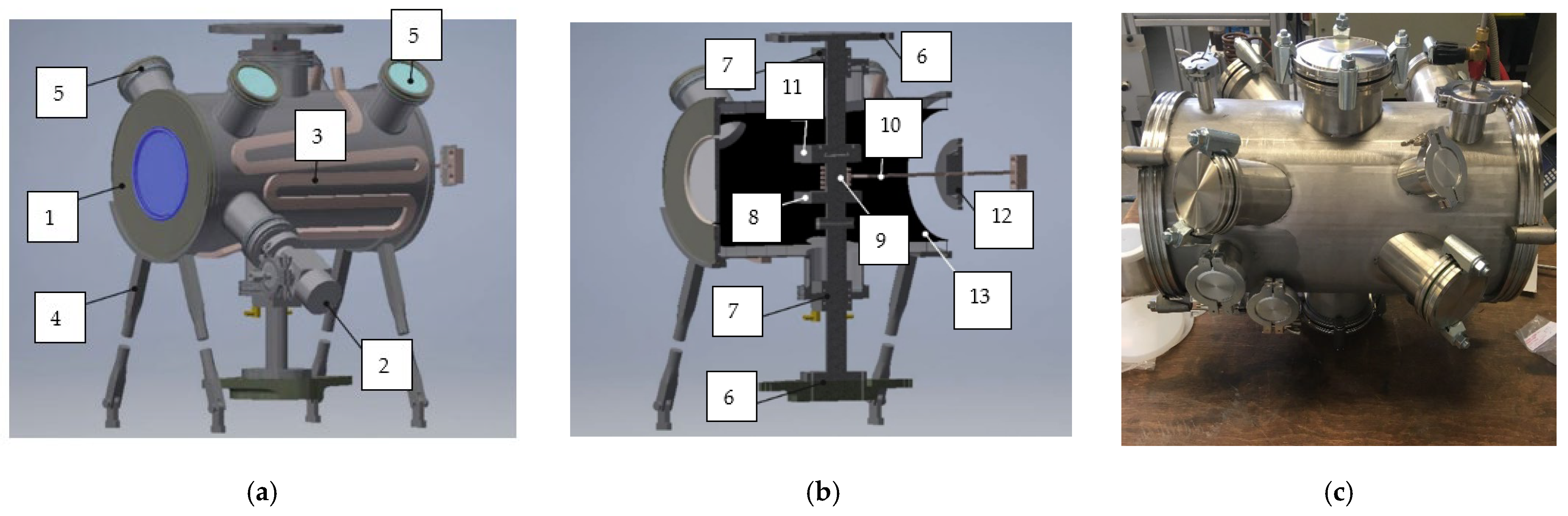
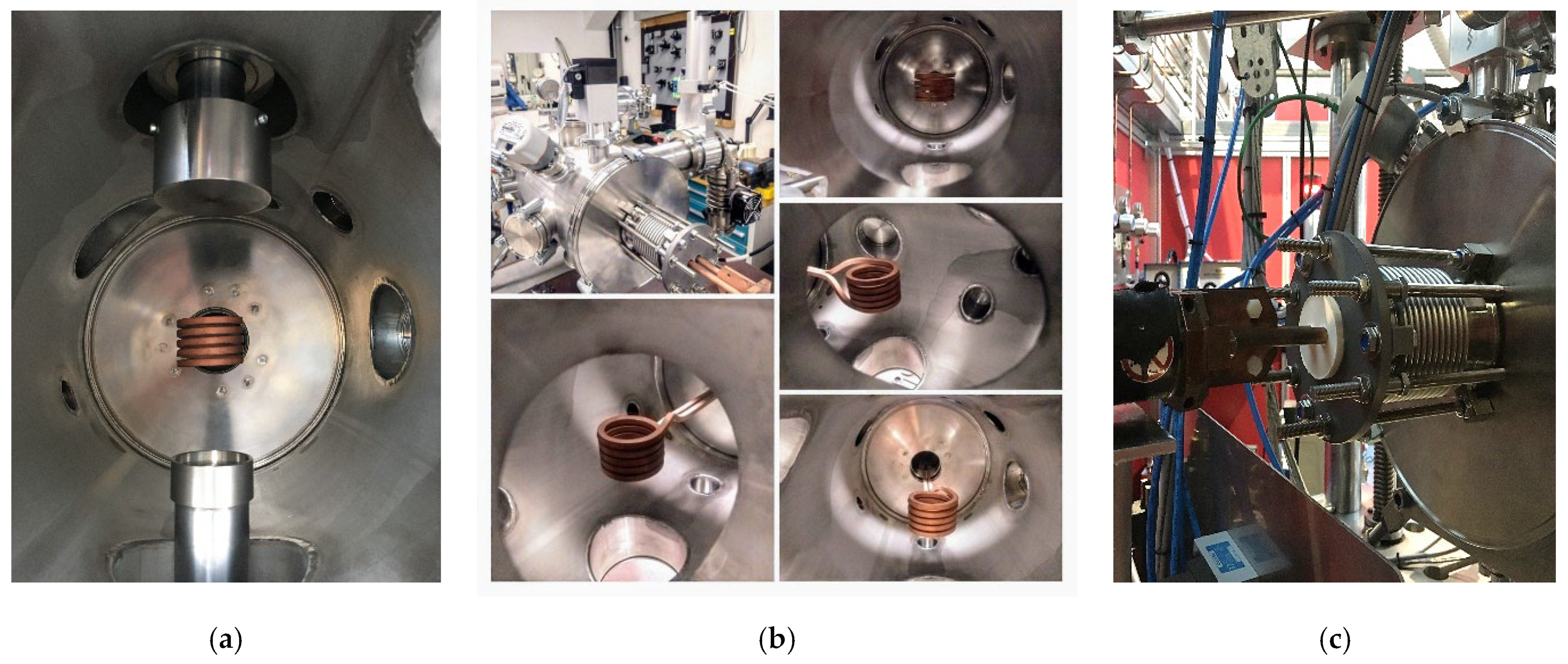
3.2.1. Vacuum Chamber—The Recipient

In parallel with the elaboration of the technical functional flow chart, the design of the pressure chamber (recipient) was carried out. This work step is also based on the specifications of the concept catalogue of the machine and the knowledge gained from existing diffusion welding systems and vacuum chambers [17,18,19,20]. However, the challenge in the context of this research project was to maintain gas tightness and vacuum safety within the recipient, despite the necessary feed of external measuring systems into its interior, accessibility for changing the specimen and the damping-free transfer of force to the joining body. The conception, production and testing of different approaches to such a structure, combined with the introduction of dynamic forces into a closed system, took up a large amount of time. This was often associated with a complete revision of the approaches.
The possibilities of the technical feasibility of the specifications made were underpinned with different concepts for force application and discussed both internally and with the project partner as well as with leading plant manufacturers in the field of the use of process chambers suitable for vacuum. The main focus of the evaluation of the solutions was on a balanced cost–benefit efficiency. The two final variants were considered.
On one hand, the application of the force into a closed system was realised via a connecting rod. In order to keep the process chamber closed/technically tight, one or more plastic seals mounted one behind the other enclose the rod and thus separate the inner from the outer area. The process chamber and the vibration generating system are thus only indirectly connected to each other. Here it is important that the plastic seals or elastomer seals have sufficient tightness against the vacuum generated in the process. Elastomer seals are in principle gas-permeable, yet they can be used for sealing vacuum chambers. Fluorine rubber, for example, is characterised by low gas permeability to air and can be used as a seal for vacuum systems with working pressure up to p = 1 × 10⁻¹¹ bar [21]. These sealing materials are very sensitive to temperature and must be protected from thermal influences coming from the process. As a result of this, the mechanical housing of the seals has been designed in such a way that it can be flowed with a cooling medium via several internal cooling channels. In this way an optimal working temperature for the seals is given.
On the other hand, an alternative variant of force application in a closed system were designed. Here, the process chamber is directly connected to the vibration-generating system/plant in order to realise the closed unit. The compensation of the movement or the transmission of the vibration to the inside of the process chamber is done by using so-called metal bellows for vacuum applications. These bellows are thin-walled cylindrical components whose outer surface is a wave structure that is perpendicular to the cylinder axis. Due to this wave structure, a high degree of mobility in the axial, as in the context of the research project, lateral and/or angular direction can be realised.
The design criterion is therefore the stroke required for the process with a simultaneous view of the service life or the possible load cycles of the bellows. This in turn depends on the bellows material used and the prevailing temperature and pressure in the process chamber. For example, austenitic stainless steels can be used for high load cycles, but their temperature resistance is limited. Since both high temperatures (T ≤ 1000 °C) and an evacuated space are the basic components of the process in diffusion welding, the equipment or the component parts must meet these requirements. Consequently, the design and process technology responded to these requirements.
Both solutions have their specific application. However, the final decision was made in favour of a design that provides for the use of several elastomer seals. These forms a very good starting position for a possible later transfer of the system from prototype to series production in terms of reliability and, of course, also with regard to economic factors such as production costs and service.
In general, the design of the recipient was revised and adapted on the basis of existing systems, such as the diffusion welding system of the company PVA Löt-und Werkstofftechnik GmbH (Wettenberg, Germany) at the Chair of Welding Technology, and in combination with ideas from the specifications (e.g. double-walled design, exchangeable punch, specific inductor feed-through). In the process, the developed constructive designs were analytically discussed and revised several times before they were implemented in terms of production technology—see Figure 3.
The design of the recipient envisaged using as many standardised components as possible for its assembly in order to keep the manufacturing effort as low as possible. For example, various standard components from Novotek Vakuumtechnik GmbH (Magstadt, Germany) made the realisation possible. The basis for the recipient was formed by the ISO-K clamp flange parts according to DIN 28,404 [22] which are used for highly vacuum-tight connections from 1 × 10⁻⁹ mbar to 1.5 bar and are used in low, medium and high vacuum technology. A connection of this type consists of two ISO-K flanges, a centring ring with an outer ring around the O-ring and clamps. Clamp screws, claws or a collar flange with snap ring and screws can be used for assembly. Depending on the vacuum requirements, the sealing is done via elastomer seals or a metal sealing ring made of aluminium.
These elements were hermetically welded by means of tungsten inert gas welding (TIG welding) and closed on the flange side with so-called ISO-K blind flanges via corresponding clamp screws. In the subsequent process, these blind flanges serve as inductor feedthroughs and as process chamber doors or process monitoring openings, for which they were subjected to various mechanical processes such as drilling and/or milling in advance. Two of these flanges (Figure 3b position 7) with a diameter of 100 mm are aligned perpendicular to the base body and flush with themselves, which allows the recipient to be divided into an upper and lower section. “ISO-K flanges with pipe connection”, as they are officially called, with the appropriate outer diameter were then placed in these holes and also connected to the base body by means of TIG welding.
In the final process, the connecting rods for applying force to the chamber run through them. This also includes the integration of the selected feed-through and connection variants into the closed system by means of an elastomer seal for the connecting rod. The constructive and final implementation of the elastomer seal in connection with the connecting rods is shown in Figure 4. At the respective end points of the connecting rods are the mechanical interfaces to the Power Swing system by SincoTec Test Systems GmbH (Clausthal-Zellerfeld, Germany) (Figure 4b), adapter plates with a corresponding hole pattern.
On the opposite end of each connecting rod are the ram platforms (Figure 5a), on which the component is positioned centrally to the inductor and then clamped or pressed by moving the connecting rods together. These platforms are also screwed to the connecting rods via corresponding threaded holes. A positive side effect of this type of construction is that the shape and, above all, the distance between the platforms can be varied with little effort if the specimen geometry is changed.

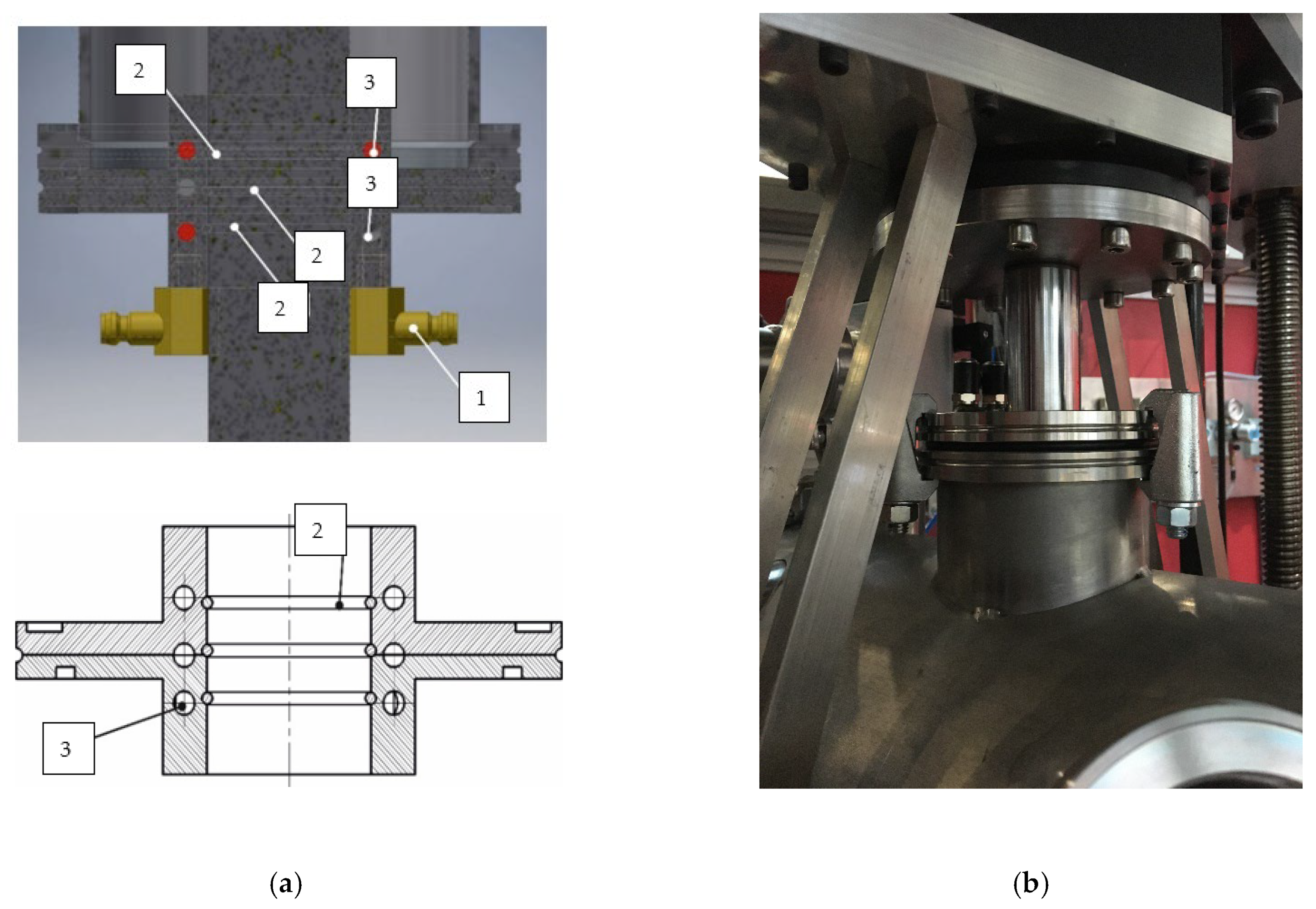
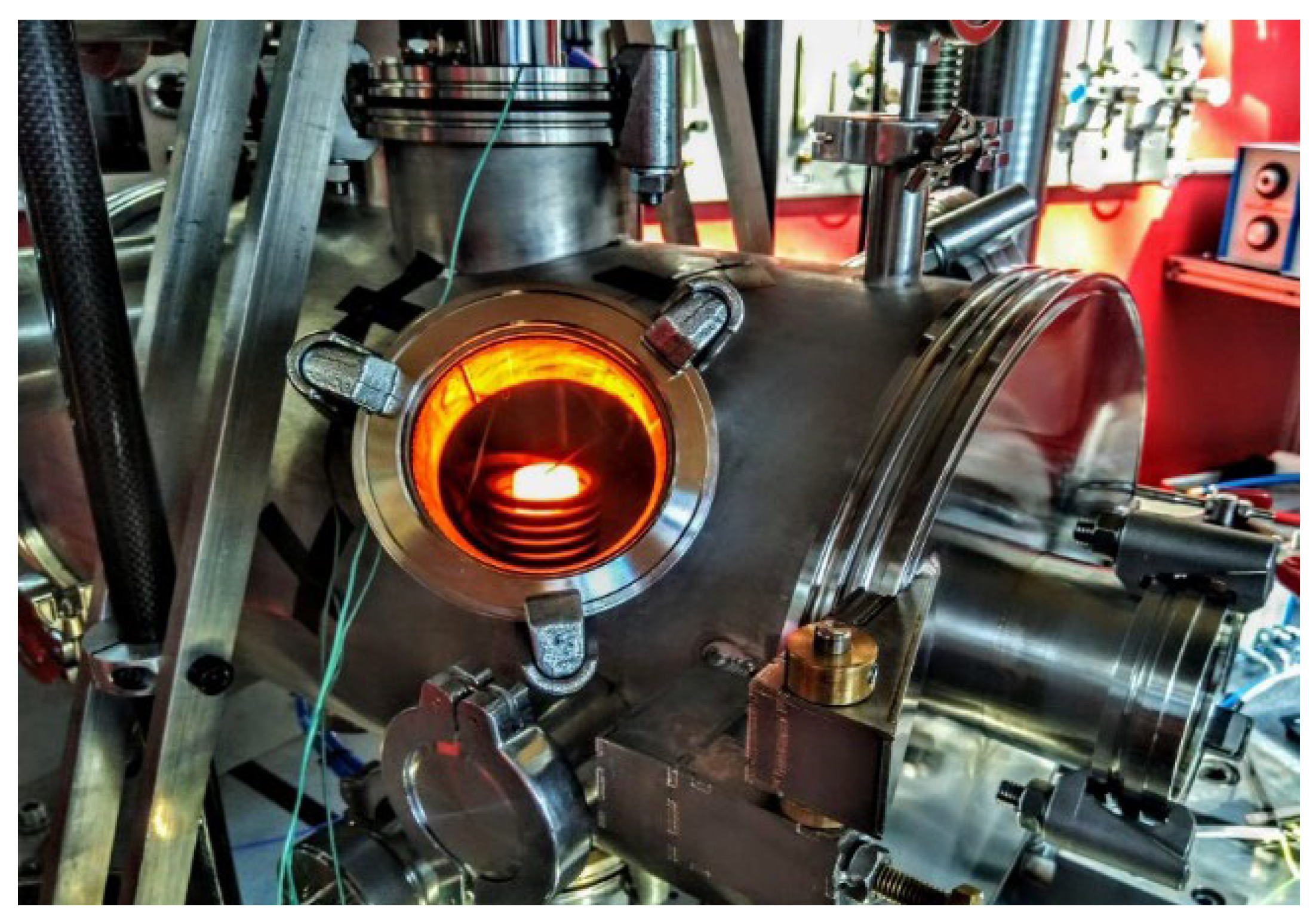
3.2.2. Sample Heating System

Another core element of the later diffusion welding system is the system for heating the specimens in the process. This is done using a frequency generator (MINAC 12/18; current/power output 140 A/17 kW; operating frequency between 10 Hz and 40 Hz) from EFD induction GmbH (Freiburg im Breisgau, Germany), which makes it possible to heat components to a desired temperature within a few minutes without contact via an inductor coil (inductance: 0.2 µH < L < 0.6 µH).
The spatial environment around the coil is only minimally indirectly affected, which is an advantage for the process, but is most important with regard to the temperature resistance of the elastomer seals. However, heat radiation to the walls of the recipient (heat shield) or heat conduction via the punches to the seals must be considered critically. This is minimised by defined welding times and ceramic insulators between the punch and heated samples.
The shape of the inductor must be specifically adapted to the shape and size of the component to be heated in order to realise effective heating [23,24]. Thus, the shape of the inductor is precisely adapted to the sample size defined in the research project, whereby the samples are arranged during the process in such a way that their joining zone is aligned exactly centrally to the coil geometry in all three dimensions. The coil itself was bent from a copper square profile. Inside this profile, a coolant flows in the later process to regulate the coil temperature and thus protect the coil from overheating. The coolant is supplied via the cooling water system of the frequency generator.
Since the subsequent joining processes will take place under defined atmospheric conditions, the working area of the coil, which is spatially separated from the frequency generator, also had to be adapted. This means that the coil had to be guided into the interior of the recipient by means of a corresponding design adaptation, while at the same time maintaining the atmospheric conditions. This is realised by means of a specific feed-through. This feed-through is also subject to exact specifications. It must be hermetically sealed and have a high thermal resistance, and in parallel it must not cause an electrical short circuit between the inductor and the frequency generator. This was achieved by using a castable insulating material (epoxy resin adhesive) and by adapting the design of the coil in this area. The feedthrough itself was made of a magneto-dielectric material.

3.2.3. Control of the System

With reference to the division of responsibility into “plant technology” and “process unit”, SincoTec Test Systems GmbH revised the existing plant technology, including preparations for the integration of a process chamber. This complex of topics included the integration of the control/regulation of the induction unit and the control of the generation of the process-relevant vacuum in the control algorithm of the plant technology. At the same time, the SincoTec employees also provided specific mechanical interfaces.
Before starting the process, the process engineer has to determine which parameters are to be used to implement the joint. Different options can be selected, such as:
  • With and without heating;
  • Under vacuum or inert gas atmosphere;
  • According to the type of pressure control (force- or distance-controlled).
This results in four different scenarios for programming the control, each with two subgroups related to the type of pressure control, and this is summarised in Table 1.
The implementation of these scenarios is achieved by extending the control system in the plant by creating a specific sub-programme called “diffusion welding” and adding the corresponding programming. For this purpose, an additional control module (SIMATIC S7-1200 by Siemens [München, Germany]) was integrated into the existing plant system and electrically wired and programmed by the welding technology department.
Above all, careful virtual programming of the control system and a larger number of reference welds in the existing system made it possible to reduce the testing of the newly developed system within the project duration. The selected control system thus not only enables the realisation of the different scenarios, but also the recording of further metrological variables (e.g., temperature measurements via thermocouples) through corresponding analogue inputs.
Likewise, in the programming of the plant and process control, plans were drawn up to adapt the necessary measurement technology of the plant to the new tasks. The aim was to generate statements about the joining process depending on the different material properties (e.g., modulus of elasticity, melting temperatures of the materials, etc.) via the damping behaviour of the joining surface or via the change in frequency in the pressure threshold range during the joining process at different temperatures. The high resolution of the Power Swing measuring system required for this enables the recording of a change in the damping in the mW range or the frequency in the range of 1/1000 Hz, so that the joining process can be analysed in situ.
The distance measuring system selected for this purpose essentially consists of two crossbeams and two stiff cantilevers—see Figure 6. The recipient or the plungers are connected to the cross beams. Capacitive distance transducers with a measuring range of 0.2 mm at a dynamic resolution of 4 nm and a linearity of 0.2 % are installed on the arms. This means that the distance can be measured against the lower crosshead. However, this high-precision measuring system also requires a defined sequence in the sub-sequent process. For example, the distance measuring system can only be set after the load has been approached and the joining temperature has been reached, i.e., a static preload is approached as the first process step, then the joining temperature is set and then the displacement sensor is set up and only then can the joining process be realised. Otherwise the measuring range would be permanently exceeded/undershot.

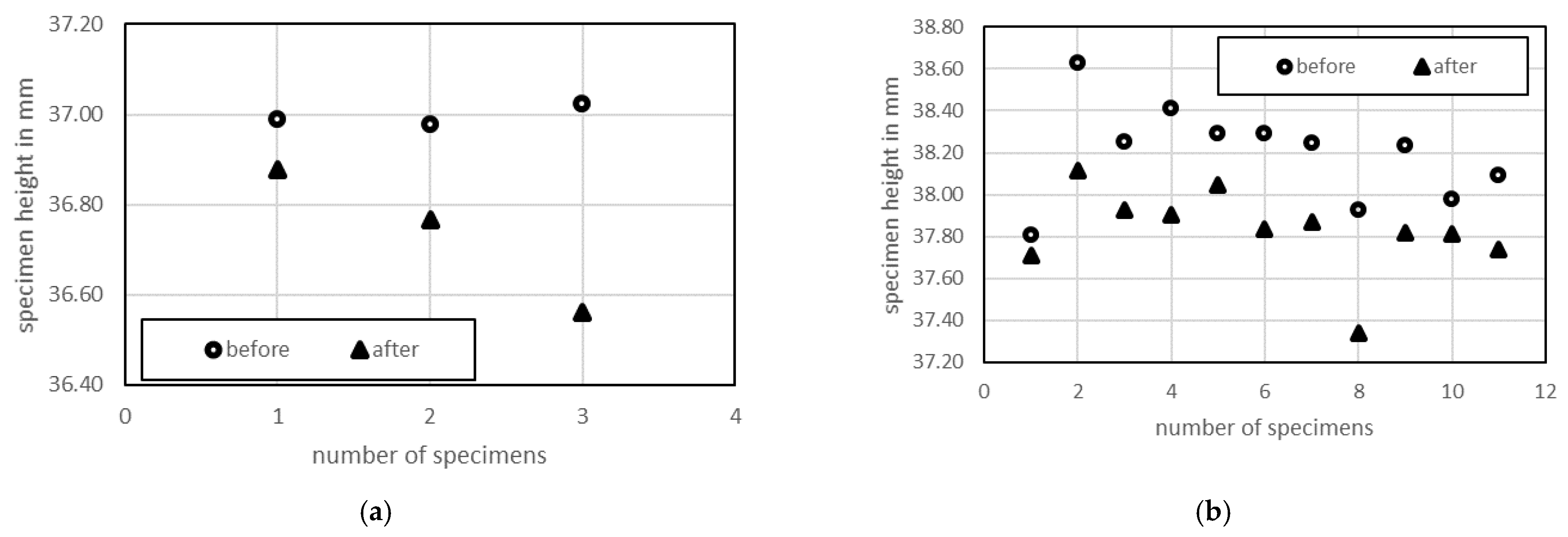
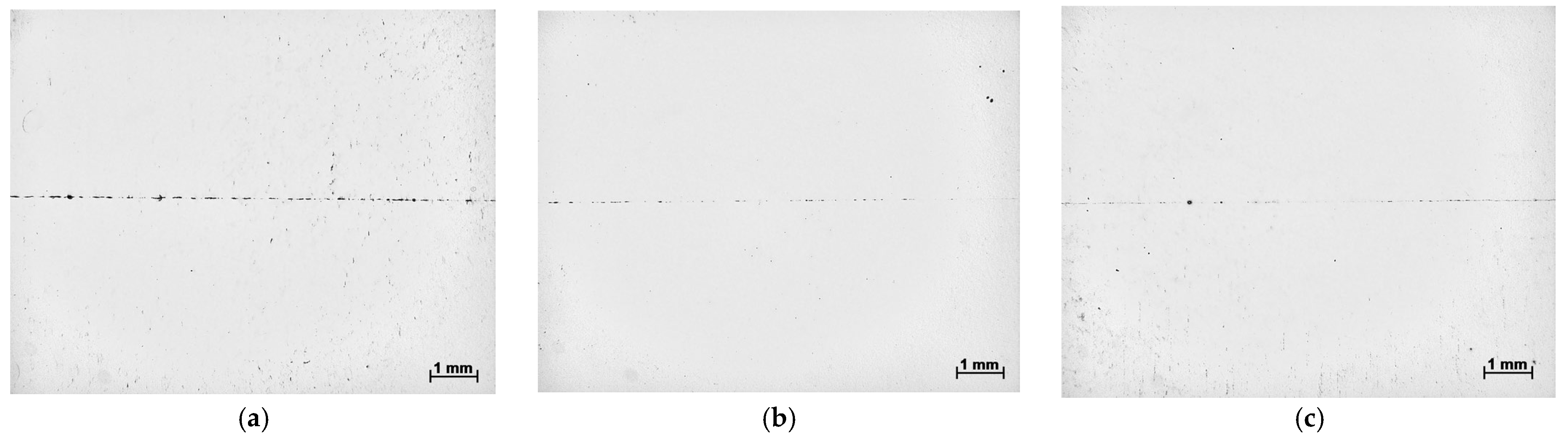
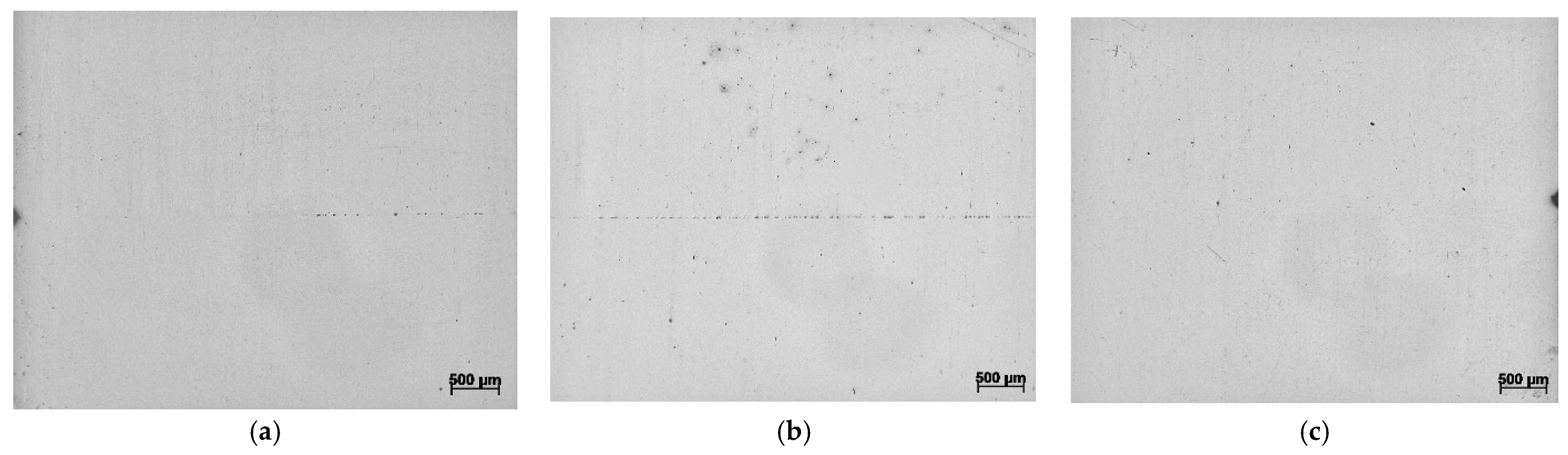
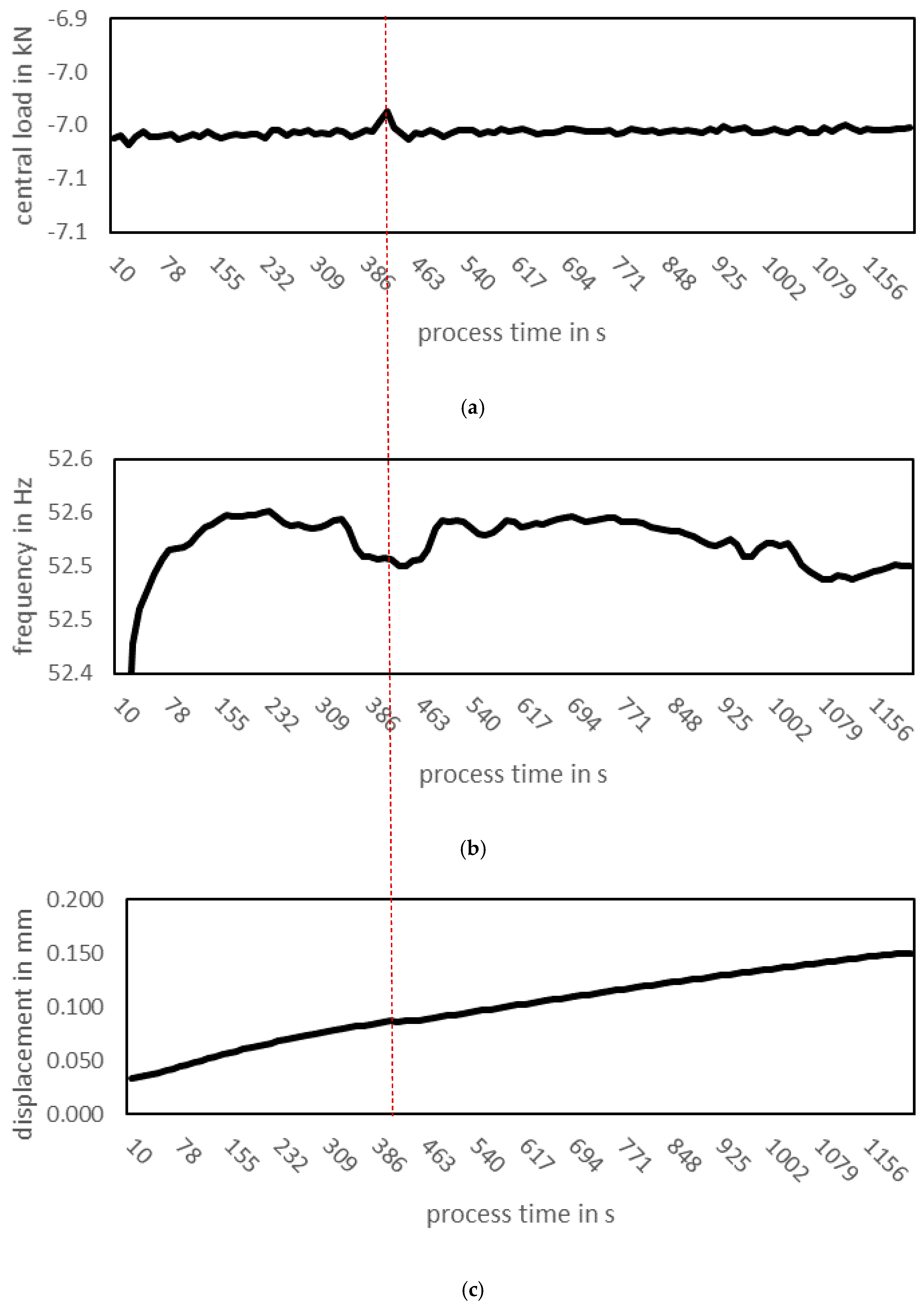
4. Results—Benchmarking Samples

In the course of the project and the realisation of the plant technology, there were always points at which the design decisions made had to be checked, evaluated and, if necessary, discarded in order to improve the final plant on the basis of the knowledge gained.
Thus, the discussion about a targeted introduction of dynamic forces into closed systems was held several times and individual variants were tested. The resulting advantages/disadvantages of the respective solutions with regard to their use in diffusion bonding were also incorporated into the planning of the further procedure. As a result, the decision was made in favour of the variant that was decoupled from the recipient by means of elastomer seals.
Likewise, the welded seams were repeatedly checked for quality during the assembly of the recipient. After completion of all weld seams on the recipient, it was checked for tightness. The first step was a classic water bath test [25]—immerse the completely sealed recipient in a basin of water, pressurise it with compressed air and check whether and where bubbles begin to form. The detected defects were reworked in terms of welding technology. Subsequently, the recipient was connected to the vacuum pump and a vacuum was created inside it. Depending on the test result, the welds were then professionally reworked and checked again.
Furthermore, the interaction of the Power Swing system with the recipient was tested in studies. For this purpose, for example, the recipient with selected elements was handed over to the company SincoTec Test Systems GmbH at an early stage of production in order to check whether all mechanical interfaces function together and whether the vibrations generated by the system might have a negative effect on the recipient. As a result, only adjustments were made to the support profiles and the displacement measuring system.
After the completion, return and installation of both system components to the welding technology professorship, the testing/verification of the interaction of the electrical interfaces between the system controls (recipient/SincoTec control) began, as well as the verification of individual process steps—pressure build-up, vibration generation, vacuum generation, heating via induction (Figure 7) as well as heat generation over time within the recipient, etc. The last point in particular is of enormous importance with regard to the tightness of the system and the generation of a process-relevant vacuum. In the tests it could be shown via installed thermal sensors that the area in which the connecting rod seals are located, which are also actively cooled via a system, do not reach a temperature range greater than 100 °C even over a longer period of time (t > 20 min). This is completely sufficient for welding times of less than 20 min and a heat tolerance of the seals of TGrenz = 150 °C.
Parallel to this, different welding tests were carried out in the diffusion welding system of the company PVA Löt-und Werkstofftechnik GmbH, which is available at the Chair of Welding Engineering at Chemnitz University of Technology. The aim was to realise sufficient reference welds in order to compare these with the samples from the newly developed facility and to provide evidence for the correct functioning of the new system concept. Relevant data relating to the welding tests were recorded and evaluated, starting with the component heights (Figure 8) before joining, the temperature profile and the application of the required joining forces during the process up to metallographic examinations afterwards to evaluate the joining zone. The difficult-to-weld steel grades 1.7227 (42CrMoS4) (a quenched and tempered steel with high toughness and strength, but which is very difficult to weld and therefore not suitable for welded constructions. Mainly used in mechanical engineering, vehicle and automotive construction [e.g. for gear wheels, gear and crankshafts] [26]) and 1.0503 (C45) (an unalloyed structural steel that is not suitable for welded constructions due to its poor weldability, as it causes stress cracks when cooled uncontrollably [27]) were used as test materials to illustrate the potential of diffusion welding. These samples were prepared differently in advance. For example, samples were prepared that were simply turned to size and then welded, and samples were prepared that were ground to size again after turning in order to achieve a homogeneous surface with a roughness of Ra = 0.2 µm. The downstream analyses of the samples show that the process in the PVA plant works in principle and that welded joints of any kind—of the same type (1.7227 + 1.7227 or 1.0503 + 1.0503) and/or of different types (1.7227 + 1.0503)—can be realised. Three weld samples were always created per process run. However, a look at the required joining time and the sample heights after joining reveals a clear shortcoming of this system technology.
The times required to join individual components together are quite long compared to other joining methods. Joining times of less than 60 min are not recommended for a selected material combination of 1.7227 + 1.0503. This becomes clear, for example, in Figure 9 where different process times were used and the joints were examined metallographically afterwards. It is noticeable that at a process time ≤ 20 min and also at ≤40 min, the joining zone is still clearly visible. This is no longer the case for process times longer than 60 min. However, the exact point in time at which an optimal joint is realised can only be determined by a large number of tests with a fine gradation of the process time. Furthermore, this statement is only valid for this material pairing and cannot be transferred to others.
The sample heights before and after the joining process were also determined. This showed that the samples before joining generally had a height delta of 0.05 mm to each other across all samples. After the joining process in the PVA Löt-und Werkstofftechnik GmbH plant, the height delta between the three samples of a process run was greater by a factor of more than 4—see also the diagrams in Figure 8. As expected, a similar height delta should occur between the specimens with a smaller total height of the specimens after joining. The fluctuation that occurs can therefore be explained by an inaccurate force distribution within the existing system technology. This can lead to joining errors that are dependent on the specimen positioning within the plant.
The first welding tests and trials with the newly developed recipient in combination with the Power Swing system from SincoTec Test Systems GmbH counteract the effects of the old system described above and enable joining technology connections to be made in a fraction of the time while simultaneously recording a large number of measurement data.
Furthermore, the metallographic investigations also indicate a significant improvement in the joining time compared to the old system previously used. Comparable results could be achieved up to a factor of 5 or 6 times faster than the conventional joining time previously allowed—see also Figure 10. The metallographic examinations show a similar number of newly formed transitions between the joining partners after a process time of 10 min as they appeared in the old system only after 40 min or 60 min.
Also reflect the recorded measurement data the complete process sequence and, based on distinctive points in the curves, allow interpretations of the joining state or starting points in the immediate vicinity of which more intensive investigations are worthwhile. As an example, the red line shown in Figure 11 shows a correlation between the applied centre load, the vibration frequency and the upsetting path. This suggests that at this temporal point in the process there is a settling behaviour between the samples—a first plasticisation phase occurs between the surface roughness peaks. Such points are crucial for the development of appropriate quality criteria.
It can therefore be assumed that the recipient realised within the framework of the “freqDiff” project in combination with the Power Swing system from SincoTec Test Systems GmbH has a general functional condition and, through the dynamic application of joining forces in the swelling range, noticeably reduces both the joining time and the technical effort required for surface preparation when joining components over a wide area.
The basic idea of the application was that with increasing joining area, the natural frequency as well as the amount of energy for applying the joining force and thus the stiffness of the system, which the developed pressure pulse system and system software detects and documents, increases. Like in [8,28,29] or [9], the welding tests on our side with the newly developed system technology also showed this. In addition to improving the joining time and minimising the effort required for surface preparation, the measurement data recorded during the joining process were also striking for several welds—see Figure 11.
Furthermore, in the evaluation of the vibration frequency curves and their comparison, a striking point is noticeable which, independent of the surface preparation, occurs from a process duration of approx. 5 min (300 s) to 7 min (420 s). At this point, the oscillation frequency seems to experience a kind of damping and drops for the first time during the processes. The extent to which this effect is related to the formation of the joint and whether it can be used to develop a quality criterion for such welds or whether this effect has no influence at all and is merely an inaccuracy in the measurements, could all be specified and verified in further investigations.
Finally, discussions are still underway on how the recorded measured variables of the welding results can be converted and processed into specific control variables for the system. SincoTec Test Systems GmbH and the Chair of Welding Engineering are endeavouring to work on this point and thus exploit the potential inherent in the process technology of diffusion welding in combination with the modification of an oscillating test rig for the dynamic application of joining forces in the threshold range.

5. Conclusions

In conclusion, the project “freqDiff—Development of a testing and joining system with frequency-superimposed force application for material bonding and testing of materials with a novel test criterion” can be considered a success as the first step to improve the diffusion welding process. An existing system technology was modified in such a way that it makes it possible to noticeably reduce joining time of diffusion welding processes or to reduce the technical effort required for surface preparation of diffusion welded specimen.
Compared to the original project schedule, the complexity of the topic meant that more time had to be invested in the technical implementation of the coupled innovative ideas. Since the construction of the recipient was based on specific boundary conditions (gas tightness/vacuum safety; feed of external measuring systems into the interior of the recipient; accessibility for changing samples as well as damping-free force transmission to the joining body), the conception, production and testing of different approaches to a solution for such a construction was modified, tested and revised several times.
The technical implementation of the system at the end of the project and the carried-out welding tests demonstrate the general functionality of the system, and also show a significant improvement in the joining results with regard to component preparation and welding time. This is reflected in several benchmark tests on the system in comparison to an existing diffusion welding system. However, the concrete derivation of quality criteria is not yet possible at this point in time due to the collected measurement data. This means that it has not yet been conclusively clarified how the recorded measured variables are related to the welding result and which exact control variables can be derived for the process and the system. These points determine the research goals of both project partners in further investigations.

Author Contributions

Conceptualisation, B.J. and H.L.; writing—original draft preparation, B.J.; writing—review and editing, J.W., M.H. and J.H. All authors have read and agreed to the published version of the manuscript.

Funding

This research was funded by the Federal Ministry for Economic Affairs and Climate (ZIM research project ZF4012633FH9) based on a resolution of the German Bundestag. We would like to take this opportunity to thank them. Metals 13 00547 i001

Data Availability Statement

The data presented in this study are available on request from the corresponding author.

Acknowledgments

We would also like to thank all the staff involved in the project at the SincoTec Test Systems GmbH for the test materials, auxiliary joining elements and services provided in the years 2020 to 2022 to carry out this research project, as well as for the support and constructive discussions.

Conflicts of Interest

The authors declare no conflict of interest.

References

  1. Matthes, K.-J.; Richter, E. (Eds.) Schweißtechnik–Schweißen von Metallischen Konstruktionswerkstoffen; Fachbuchverlag Leipzig: Leipzig, Germany, 2002. [Google Scholar]
  2. Akca, E.; Gürsel, A. The importance of interlayers in diffusion welding-A review. Period. Eng. Nat. Sci. (PEN) 2015, 3, 2. [Google Scholar] [CrossRef]
  3. Günther, W.-D.; Mehlhorn, H.; Wiesner, P. Diffusionsschweißen; Verlag Technik Berlin: Berlin, Germany, 1978. [Google Scholar]
  4. Basuki, W.W. Optimierung der Diffusionsschweißparameter von Hastelloy® C-22® zur Herstellung von Mikrowärmetauschern; Forschungszentrum Karlsruhe GmbH: Karlsruhe, Germany, 2008. [Google Scholar]
  5. Kolukisa, S. The effect of the welding temperature on the weldability in diffusion welding of martensitic (AISI 420) stainless steel with ductile (spheroidal graphite-nodular) cast iron. J. Mater. Process. Technol. 2007, 186, 33–36. [Google Scholar] [CrossRef]
  6. Ben-Haroush, M.; Mittelman, B.; Priel, R.S.E. The Influence of Time, Atmosphere and Surface Roughness on the Interface Strength and Microstructure of AA6061–AA1050 Diffusion Bonded Components. Materials 2023, 16, 769. [Google Scholar] [CrossRef] [PubMed]
  7. DIN EN ISO 21920-2; Geometrische Produktspezifikation (GPS)–Oberflächenbeschaffenheit: Profile–Teil 2: Begriffe und Kenngrößen für die Oberflächenbeschaffenheit. Deutsches Institut für Normung e. V.: Berlin, Germany, 2022.
  8. Dwivedi, G.S.D.K. Effect of pressure pulsation on bond interface characteristics of 409 ferritic stainless steel diffusion bonds. Vacuum 2017, 146, 152–158. [Google Scholar]
  9. Dwivedi, G.S.D.K. Diffusion bonding of 304 austenitic stainless-steel using pressure pulses. Mater. Today Proc. 2021, 44, 2135–2141. [Google Scholar]
  10. Dahms, S. Diffusionsschweißen von Werkstoffen Mit Unterschiedlichen Eigenschaften. Ph.D. Thesis, Tallin University of Technology, Tallin, Estonia, 2011. [Google Scholar]
  11. Jafarian, M.; Khodabandeh, A.; Manafi, S. Evaluation of diffusion welding of 6061 aluminum and AZ31 magnesium alloys without using an interlayer. Mater. Des. 2015, 65, 160–164. [Google Scholar] [CrossRef]
  12. Hafizi, M.; Kasiri-Asgarani, M.; Naalchian, M.; Bakhsheshi-Rad, H.R.; Berto, F. The Effect of Holding Time on Dissimilar Transient Liquid-Phase-Bonded Properties of Super-Ferritic Stainless Steel 446 to Martensitic Stainless Steel 410 Using a Nickel-Based Interlayer. Micromachines 2022, 13, 1801. [Google Scholar] [CrossRef] [PubMed]
  13. Shi, H.; Qiao, S.; Qui, R.; Yu, X.Z.H. Effect of Welding Time on the Joining Phenomena of Diffusion Welded Joint between Aluminum Alloy and Stainless Steel. Mater. Manuf. Process. 2012, 27, 1366–1369. [Google Scholar] [CrossRef]
  14. Chisabas, R.S.S.; Zabala, J.P.O.; Cantor, D.F.; Loureiro, G.; Lino, C.O. Development of a Thermal-Vacuum Chamber for testing in Small Satellites. In Proceedings of the 47th International Conference on Environmental Systems, Charleston, SC, USA, 16–20 July 2017. [Google Scholar]
  15. Eisfelder, J.E. Konstruktive Betrachtungen zum Diffusionsschweißen Mit Dynamisch Modulierter Prozesskraft. Ph.D. Thesis, Fakultät für Maschinenbau TU Chemnitz, Chemnitz, Germany, 2021. [Google Scholar]
  16. Awiszus, B.; Bast, J.; Dürr, H.; Matthes, K.-J. (Eds.) Grundlagen der Fertigungstechnik, 2nd ed.; Fachbuchverlag Leipzig: München, Germany, 2005. [Google Scholar]
  17. Zhu, L.; Wu, J.; Liu, Z.; Ma, J. Design of Electron Beam Welding Vacuum Chamber for Collar Rings in CFETR Windows. J. Fusion Energy 2017, 36, 127–133. [Google Scholar] [CrossRef]
  18. Cooper, N.; Coles, L.A.; Everton, S.; Maskey, I.; Campion, R.P.; Madkhaly, S.; Morley, C.; O’Shea, J.; Evans, W.; Saint, R.; et al. Additively manufactured ultra-high vacuum chamber for portable quantum technologies. Addit. Manuf. 2021, 40, 101898. [Google Scholar] [CrossRef]
  19. Jayaram, S.G.E. Design and construction of a low-cost economical thermal vacuum chamber for spacecraft environmental testing. J. Eng. Des. Technol. 2011, 9, 47–62. [Google Scholar] [CrossRef]
  20. Jeon, J.; Lee, S.; Yoon, S.; Seon, J.; Jin, H.; Lee, D.; Lin, R.P. Construction of a Thermal Vacuum Chamber for Environment Test of Triple CubeSat Mission TRIO-CINEMA. J. Astron. Space Sci. 2013, 30, 335–344. [Google Scholar] [CrossRef] [Green Version]
  21. “3.2.2 Dichtungswerkstoffe,” Pfeiffer Vacuum GmbH. Available online: https://www.pfeiffer-vacuum.com/de/know-how/mechanische-komponenten-im-vakuum/werkstoffe/dichtungswerkstoffe/elastomerdichtungen/ (accessed on 1 September 2022).
  22. DIN 28404; Vakuumtechnik, Flansche-Maße. Deutsches Institut für Normung e.V.: Berlin, Germany, 1986.
  23. Yang, J.; Chen, R.D.H.; Guo, J.; Han, J.; Fu, H. Thermal characteristics of induction heating in cold crucible used for directional solidification. Appl. Therm. Eng. 2013, 59, 69–76. [Google Scholar] [CrossRef]
  24. Yang, Y.; Wang, X.L.S. Thermal characteristics of induction heating with stepped diameter mold during two-phase zone continuous casting high-strength aluminum alloys. Int. J. Heat Mass Transf. 2020, 152, 119479. [Google Scholar] [CrossRef]
  25. DIN EN 1593; Dichtheitsprüfung–Blasenprüfverfahren. Deutsches Institut für Normung e.V.: Berlin, Germany, 1999.
  26. Stahlhandel Gröditz GmbH. 1.7225 (42CrMo4 vergütet)|1.7227 (42CrMoS4) Werkstoffdatenblatt. Available online: https://www.stahlportal.com/lagervorrat/17225-42crmo4-verguetet-17227-42crmos4/ (accessed on 30 September 2022).
  27. Stahlhandel Gröditz GmbH. 1.0503 (C45)|1.1730 C45U Werkstoffdatenblatt. Available online: https://www.stahlportal.com/lagervorrat/10503-c45-11730-c45u/ (accessed on 30 September 2022).
  28. Yuan, X.J.; Sheng, G.M.; Qin, B.; Zhou, W.Z.H.B. Impulse pressuring diffusion bonding of titanium alloy to stainless steel. Mater. Charact. 2008, 59, 930–936. [Google Scholar] [CrossRef]
  29. Guangmin, L.J.S. Diffusion Bonding of TiC Cermet to Stainless Steel Using Impulse Pressuring with Ti-Nb Interlayer. Rare Met. Mater. Eng. 2017, 46, 882–887. [Google Scholar]
Figure 1. Schematic representation of a diffusion welding system (a) and the course of temperature and applied pressure over the process time (b) [1].
Metals 13 00547 g001
Figure 2. Possible design of a diffusion welding chamber—(a) a combination of a vacuum chamber with pressing plungers that realise the forces that were needed; (b) the charging feet allow the position-ing of the weld sample [10]. Legend: pressing device (1); corresponding pressing plungers (2); charging feet (3); vacuum pump (4).
Metals 13 00547 g002
Figure 3. Constructive implementation of the recipient. (a): Overall view of the construction including specific external parts; (b): components inside the vacuum chamber; (c): final production-technical implementation of the recipient. Legend: access to the process chamber incl. sight glass (1), connection valve for vacuum generation (2), cooling system (3), supports for positioning the recipient in the testing machine Power Swing MOT 100 kN Newline (4), additional shop windows (5), connecting elements for power transmission between the two systems (6), cooled connecting rod feedthrough incl. elastomer seal (7), lower ram platform (8), component to be joined (9), inductor (10), upper ram platform (11), inductor feedthrough (12), thermal shield (13).
Metals 13 00547 g003
Figure 4. (a) Constructive implementation of the elastomer seal. Connection for the coolant supply (1), elastomer seals in triple design (2), holes for cooling (3); (b) implemented implementation incl. interface to the Power Swing system.
Metals 13 00547 g004
Figure 5. Integration of the coil into the recipient—(a) look inside; (b) the coil photographed from different directions; (c) passage of the coil into the recipient.
Metals 13 00547 g005
Figure 6. Constructive (a) and final (b) integration of the distance encoder, a capacitive sensor (measuring range: 0.2 mm; dyna. resolution 4 nm).
Metals 13 00547 g006
Figure 7. Investigation of the effect of heat development/propagation over time in the recipient as a result of inductive component heating.
Metals 13 00547 g007
Figure 8. (a) Sample height unsanded compared before/after. (b) Sample height compared before/after sanded samples, Ra = 0.2 µm, both processed in the PVA Löt-und Werkstofftechnik GmbH plant.
Metals 13 00547 g008
Figure 9. Transverse micrographs of the joining zone during diffusion bonding of 1.0503 + 1.0503 processed in the PVA Löt-und Werkstofftechnik GmbH plant—Tweld = 900 °C, Fweld = 12.5 kN (≙ surface pressure of 10 N/mm2), process time: tweld = 20 min (a), tweld = 40 min (b), tweld = 60 min (c).
Metals 13 00547 g009
Figure 10. Transverse micrographs of the joining zone during diffusion bonding of 1.0503 + 1.0503 processed in the SincoTec Test Systems GmbH plant—Tweld = 900 °C, Fweld = 7 kN (≙ surface pressure of 10 N/mm2), vibration amplitude 1.5 kN, load change: 31,500, process time: tweld = 10 min, micrograph position: left (a) and right (c) edge or centre of the specimen (b).
Metals 13 00547 g010
Figure 11. Example of recorded parameters (mean load (a); vibration frequency (b); upsetting path (c)) during diffusion bonding of a 1.7227 + 1.0503 joint, surface untreated; Tweld = 900 °C, Fweld = 7 kN (≙ surface pressure of 10 N/mm2), vibration amplitude 1.5 kN, load change: 63,051, process time: tweld = 20 min—the red line shows a correlation between the applied centre load, the vibration frequency and the upsetting path.
Metals 13 00547 g011
Table 1. Selectable process scenarios.
Description
0 =
1 =
Heating
without
with
Atmosphere
Vacuum
Shield Gas
Pressure Control
Strength-Regulated
Travel-Regulated
scenario A 1
scenario A 2
100
101
scenario B 1
scenario B 2
000
001
scenario C 1
scenario C 2
110
111
scenario D 1
scenario D 2
010
011
Disclaimer/Publisher’s Note: The statements, opinions and data contained in all publications are solely those of the individual author(s) and contributor(s) and not of MDPI and/or the editor(s). MDPI and/or the editor(s) disclaim responsibility for any injury to people or property resulting from any ideas, methods, instructions or products referred to in the content.

