
A Study of the Metallurgical and Mechanical Properties of Friction-Stir-Welded Pure Titanium

Abstract
:1. Introduction
2. Materials and Methods
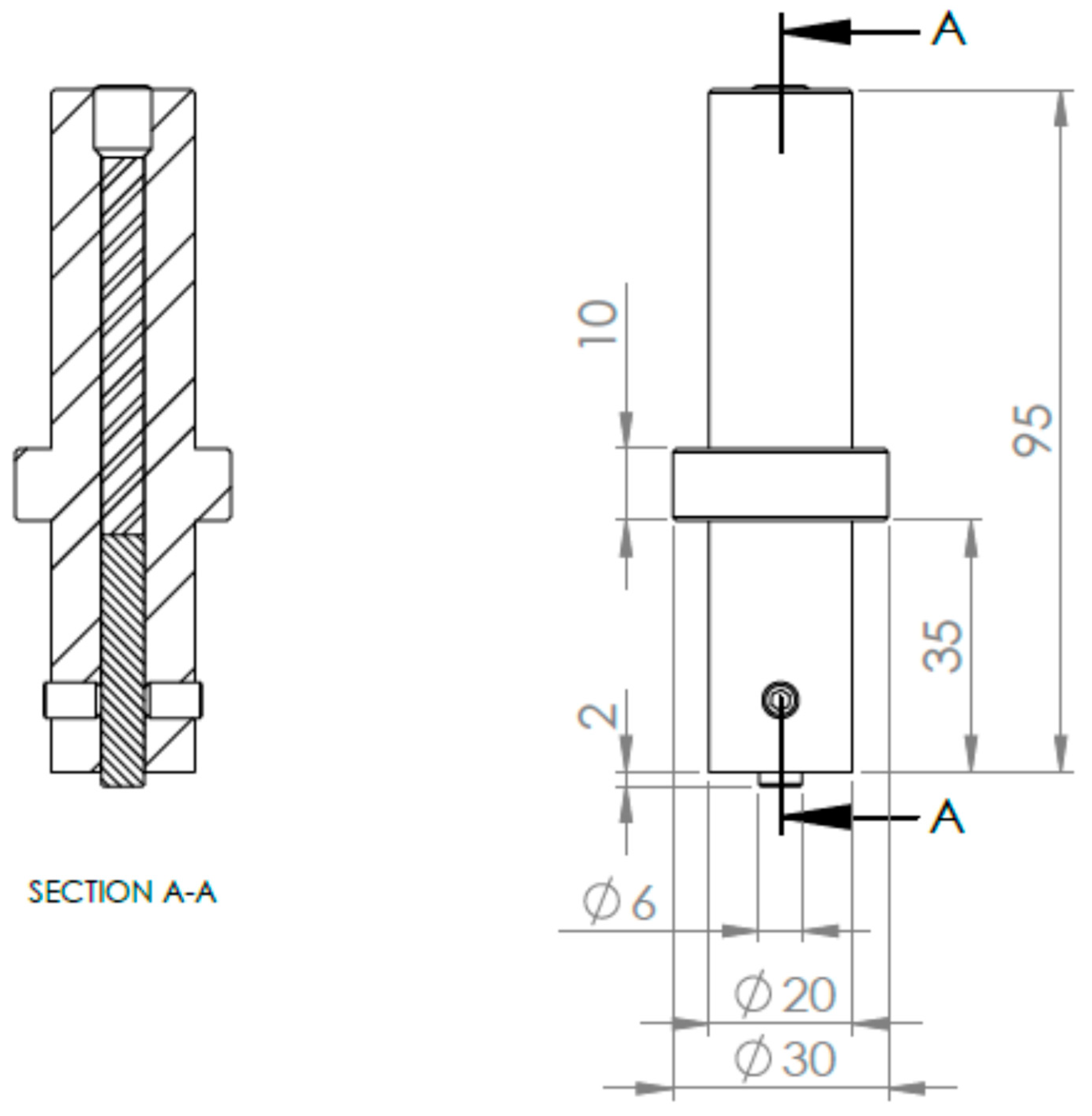
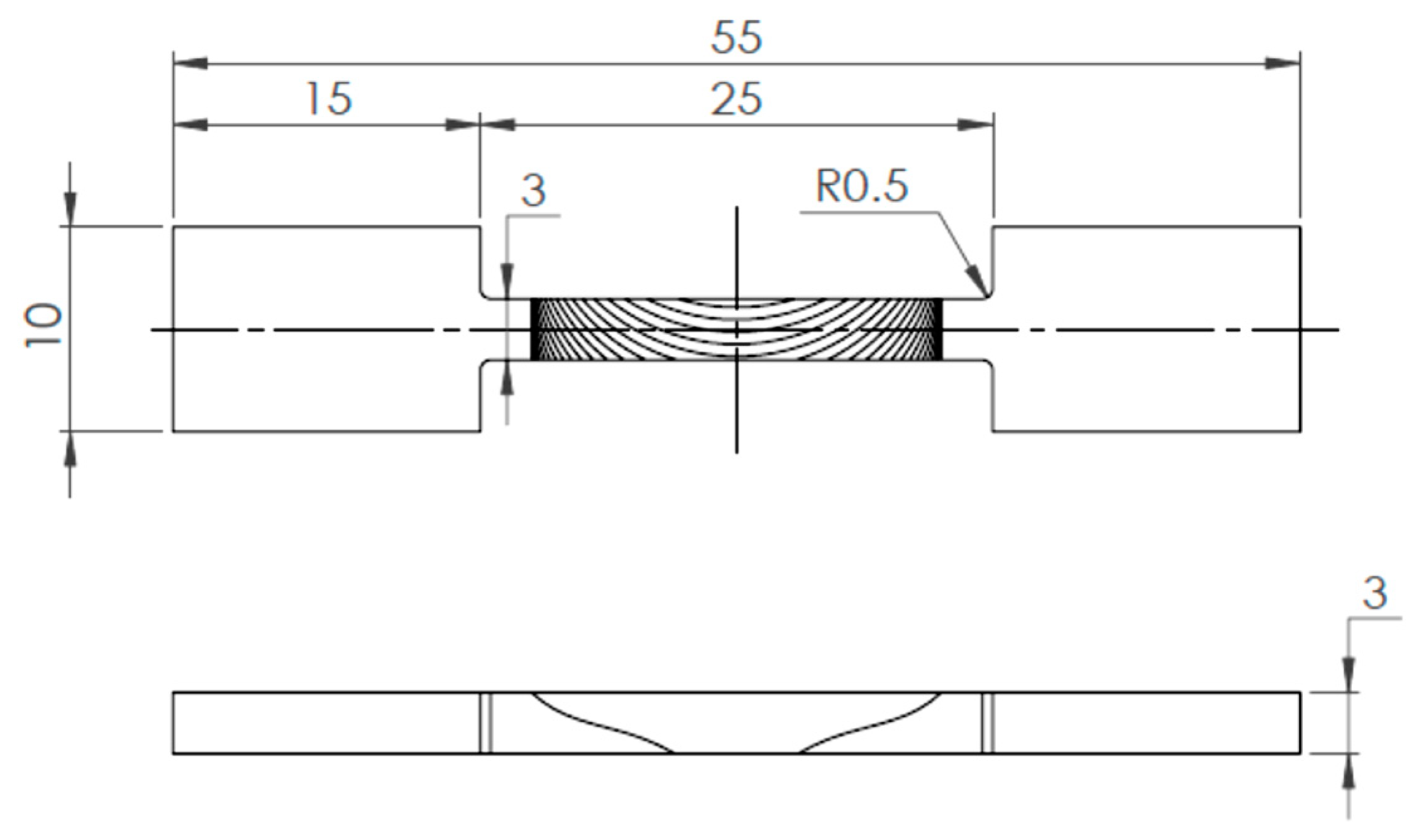
2.1. FSW-Process Optimization
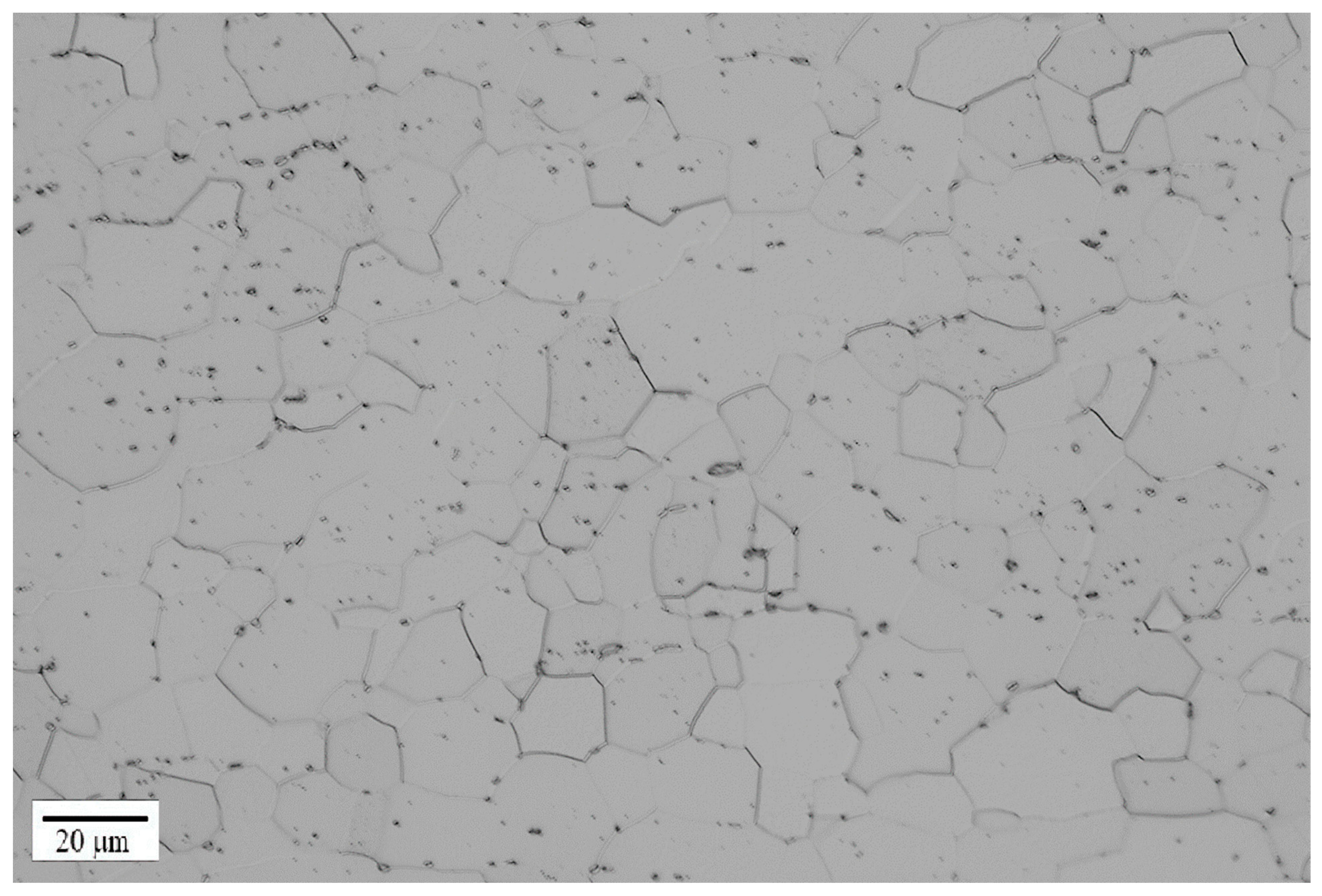
2.2. Metallography
2.3. Mechanical Properties
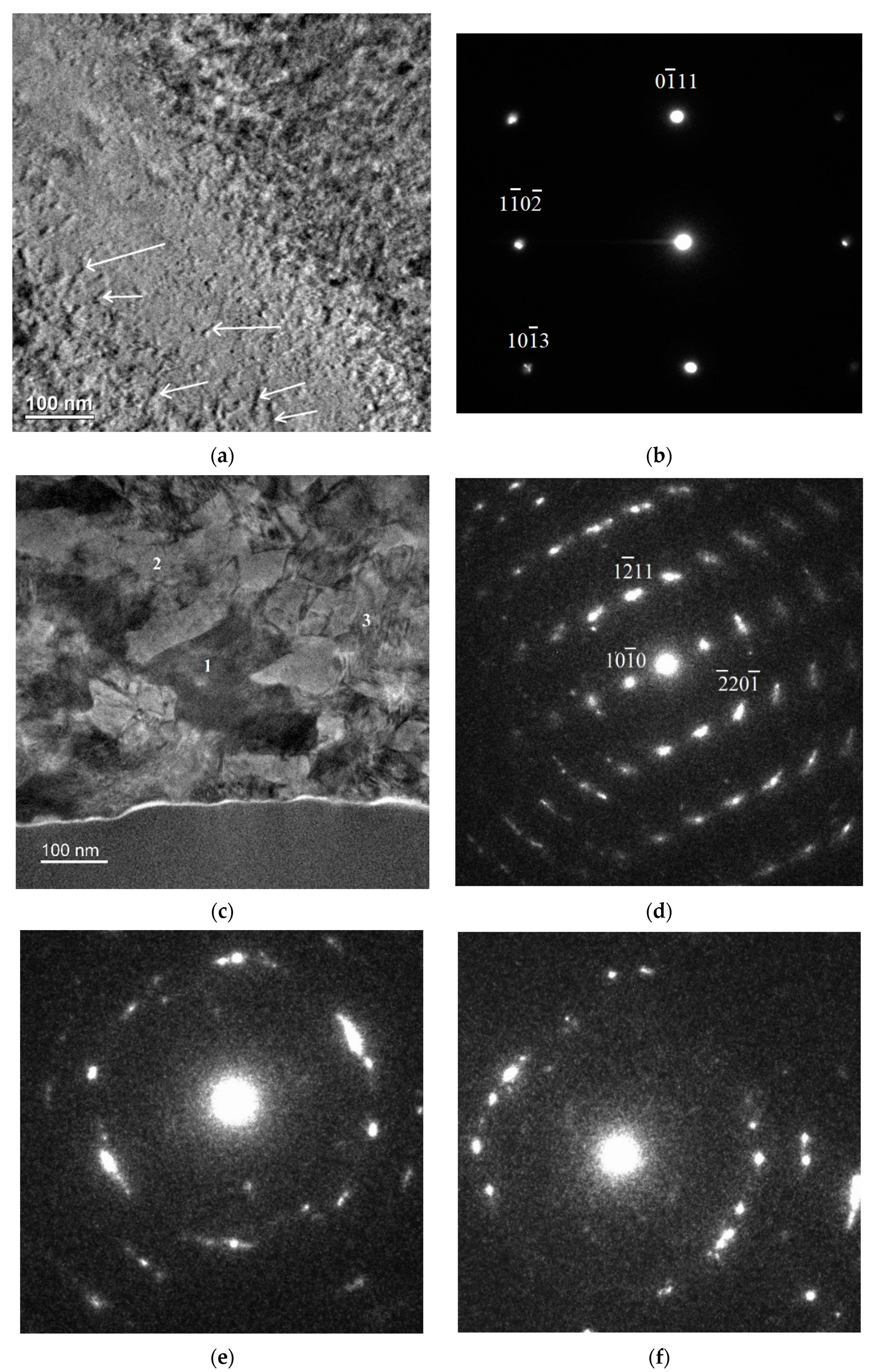
2.4. TEM
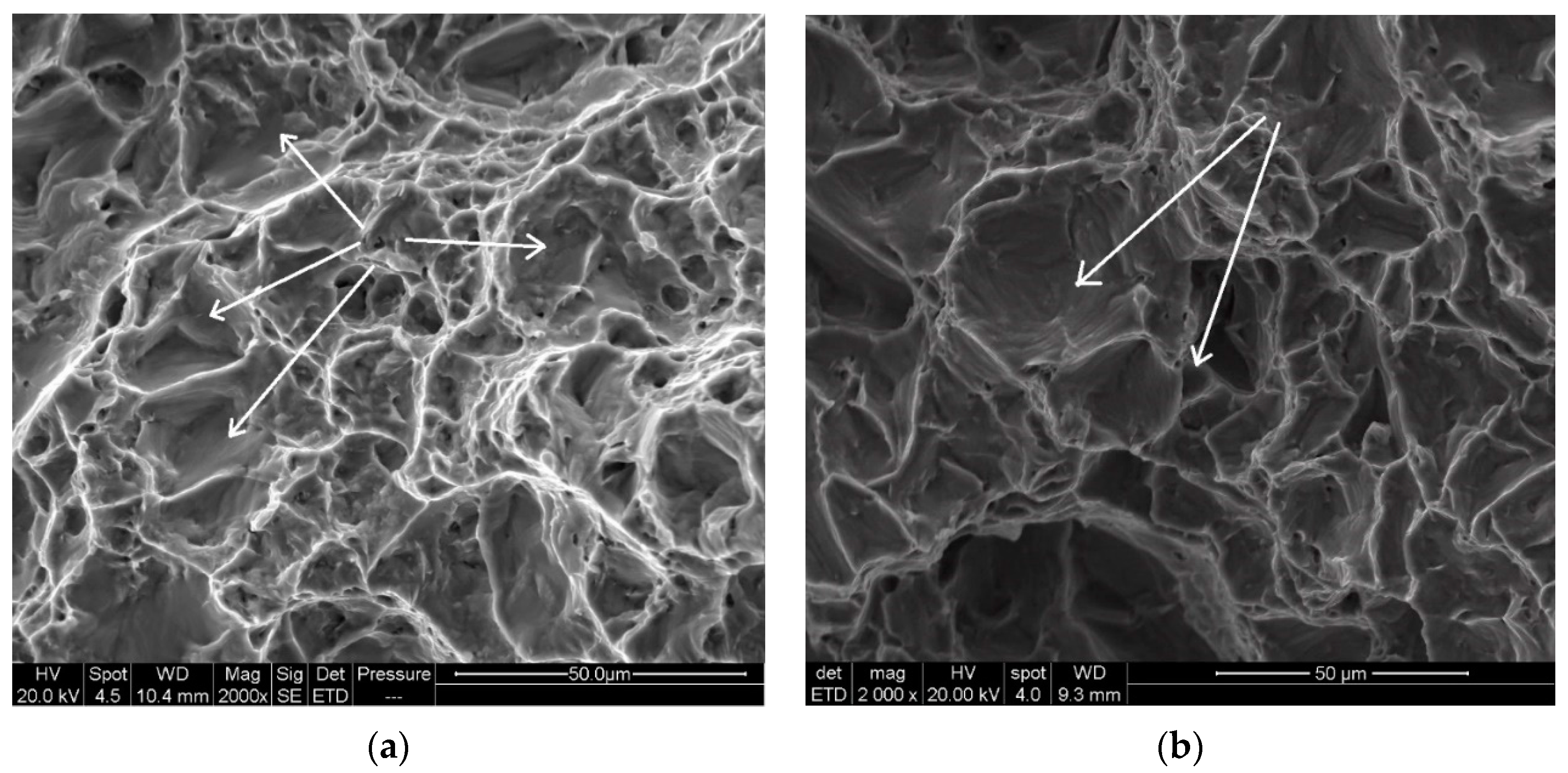
2.5. Fractography
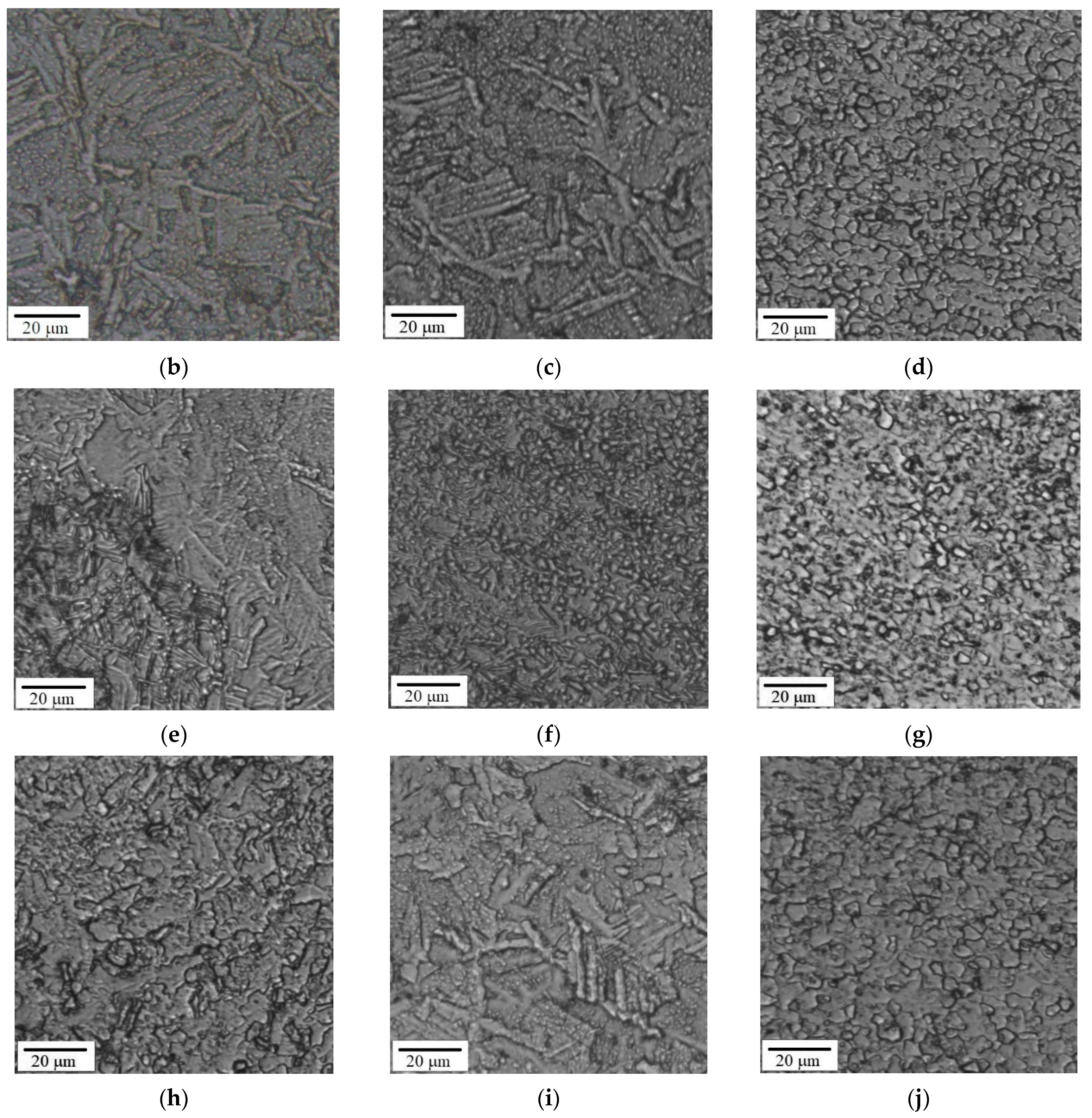
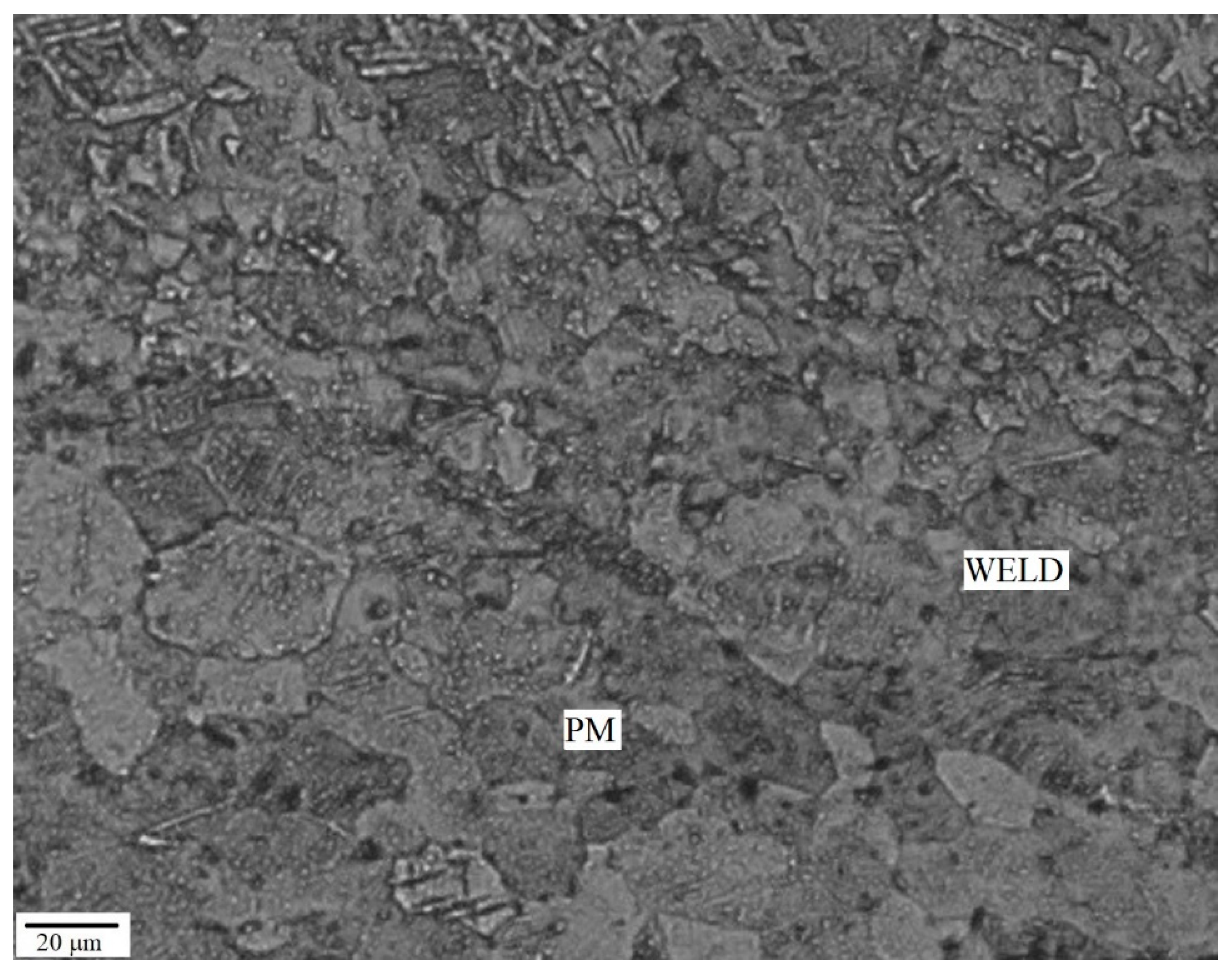
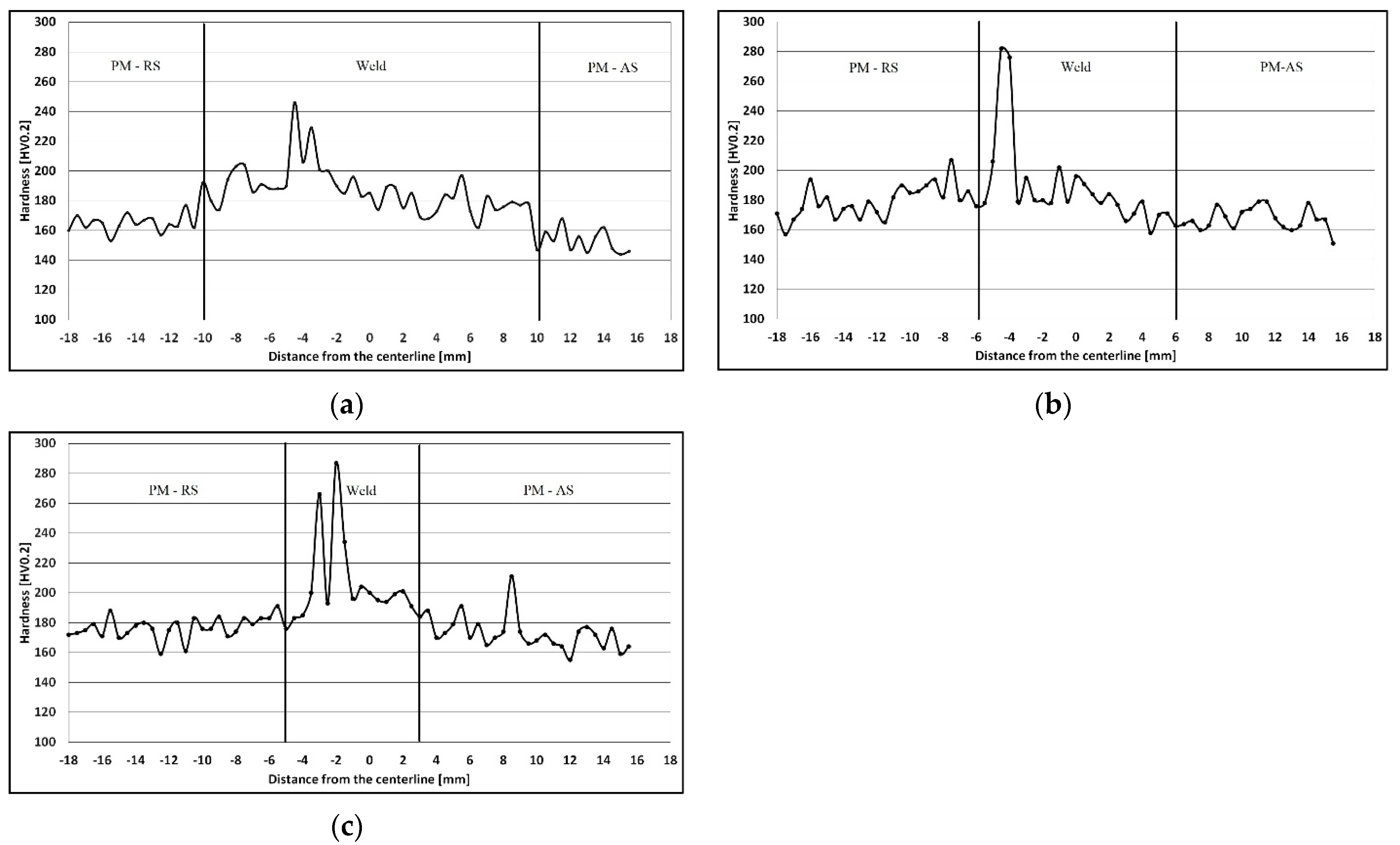
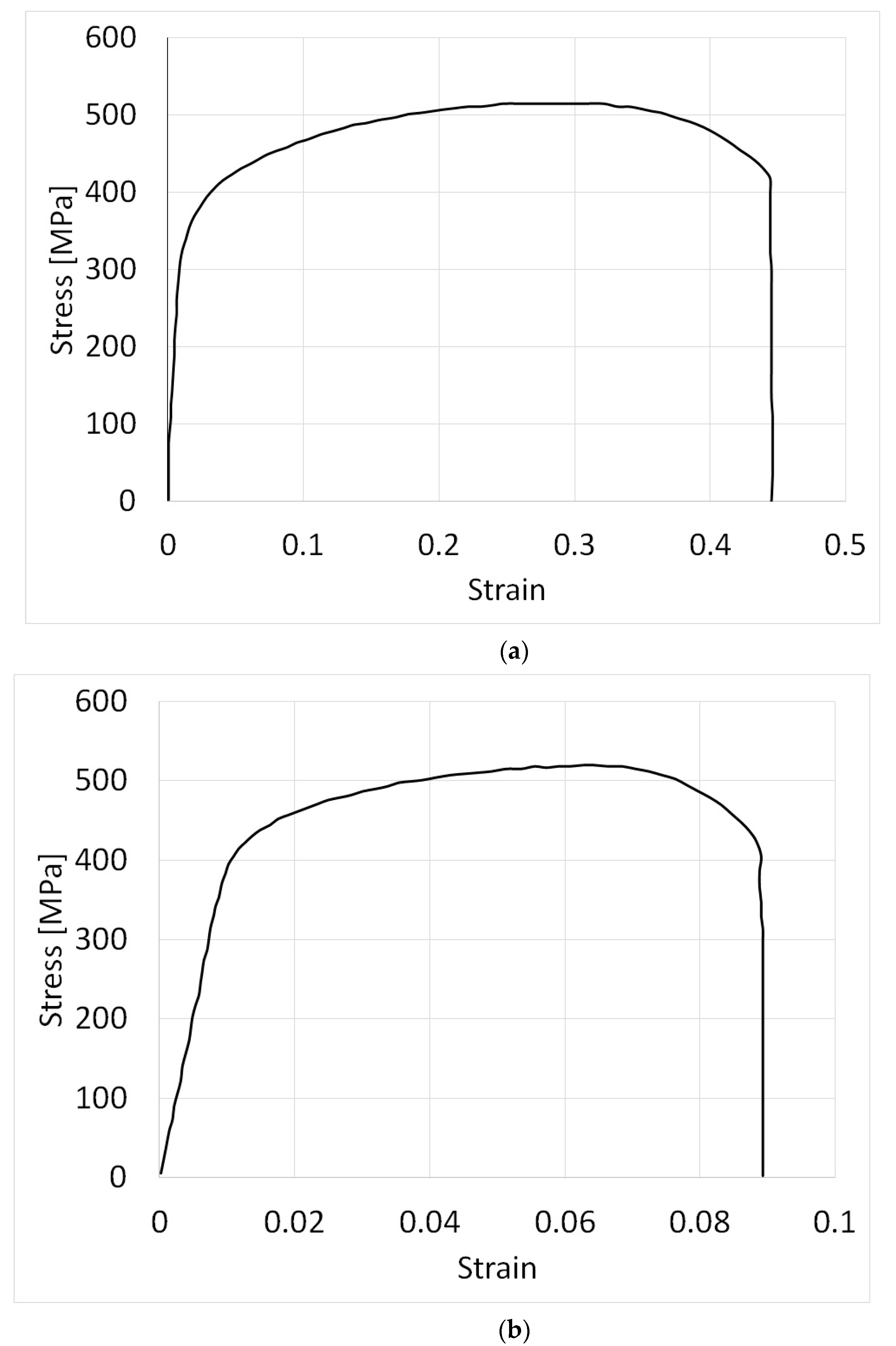
3. Results
4. Discussion
5. Conclusions
Author Contributions
Funding
Data Availability Statement
Acknowledgments
Conflicts of Interest
References
- Zhang, Y.; Sato, Y.S.; Kokawa, H.; Park, S.H.C.; Hirano, S. Stir zone microstructure of commercial purity titanium friction stir welded using pcBN tool. Mater. Sci. Eng. A 2008, 488, 25–30. [Google Scholar] [CrossRef]
- Lee, W.B.; Lee, C.Y.; Chang, W.S.; Yeon, Y.M.; Jung, S.B. Microstructural investigation of friction stir welded pure titanium. Mater. Lett. 2005, 59, 3315–3318. [Google Scholar] [CrossRef]
- Reshad Seighalani, K.; Besharati Givi, M.K.; Nasiri, A.M.; Behemat, P. Investigations on the effects of the tool material, geometry, and tilt angle on friction stir welding of pure titanium. J. Mater. Eng. Perform. 2010, 19, 955–962. [Google Scholar] [CrossRef]
- Fujii, H.; Sun, Y.; Kato, H.; Nakata, K. Investigation of welding parameter dependent microstructure and mechanical properties in friction stir welded pure Ti joints. Mater. Sci. Eng. A 2010, 527, 3386–3391. [Google Scholar] [CrossRef]
- Kim, J.D.; Jin, E.G.; Murugan, S.P.; Park, Y.D. Recent advances in friction-stir welding process and microstructural investigation of friction stir welded pure titanium. J. Weld. Join. 2017, 35, 6–15. [Google Scholar] [CrossRef] [Green Version]
- Karna, S.; Cheepu, M.; Venkateswarulu, D.; Srikanth, V. Recent developments and research progress on friction stir welding of titanium alloys: An overview. IOP Conf. Ser. Mater. Sci. Eng. 2018, 330, 012068. [Google Scholar] [CrossRef]
- Xu, N.; Song, Q.; Bao, Y.; Jiang, Y.; Shen, J.; Cao, X. Twinning-induced mechanical properties’ modification of CP-Ti by friction stir welding associated with simultaneous backward cooling. Sci. Technol. Weld. Join. 2017, 7, 610–616. [Google Scholar] [CrossRef]
- Bahl, S.; Nithilaksh, P.L.; Suwas, S.; Kailas, S.V.; Chatterjee, K. Processing–microstructure–crystallographic texture–surface property relationships in friction stir processing of titanium. J. Mater. Eng. Perform. 2017, 26, 4206–4216. [Google Scholar] [CrossRef]
- Jiang, L.; Huang, W.; Liu, C.; Chai, L.; Yang, X.; Xu, Q. Microstructure, texture evolution and mechanical properties of pure Ti by friction stir processing with slow rotation speed. Mater. Charact. 2019, 148, 1–8. [Google Scholar] [CrossRef]
- Callegari, B.; Oliviera, J.P.; Aristizabal, K.; Coelho, R.S.; Brito, P.P.; Wu, L.; Schell, N.; Soldera, F.A.; Mucklich, F.; Pinto, H.C. In-situ synchrotron radiation study of the aging response of Ti-6Al-4V alloy with different starting microstructures. Mater. Charact. 2020, 165, 110400. [Google Scholar] [CrossRef]
- Callegari, B.; Oliviera, J.P.; Coelho, R.S.; Brito, P.P.; Schell, N.; Soldera, F.A.; Mucklich, F.; Sadik, M.I.; Garcia, J.L.; Pinto, H.C. New insights into the microstructural evolution of Ti-5Al-5Mo-5V-3Cr alloy during hot working. Mater. Charact. 2020, 162, 110180. [Google Scholar] [CrossRef]
- Kang, D.S.; Lee, K.J. Recent R&D status on friction stir welding of Ti and its alloys. J. Weld. Join. 2015, 33, 1–7. [Google Scholar]
- Mironov, S.; Sato, Y.S.; Kokawa, H. Development of grain structure during friction stir welding of pure titanium. Acta Mater. 2009, 57, 4519–4528. [Google Scholar] [CrossRef]
- Liu, H.; Nakata, K.; Yamamoto, N.; Liao, J. Friction stir welding of pure titanium lap joint. Sci. Technol. Weld. Join. 2010, 15, 428–432. [Google Scholar] [CrossRef]
- Fonda, R.W.; Knipling, K.E.; Levinson, A.J.; Feng, C.R. Enhancing the weldability of CP titanium friction stir welds with elemental foils. Sci. Technol. Weld. Join. 2019, 24, 617–623. [Google Scholar] [CrossRef]
- Mahoney, W.M. Mechanical properties of friction stir welded aluminum alloys. In Friction Stir Welding and Processing, 1st ed.; Mishra, R.S., Mahoney, W.M., Eds.; ASM International: Materials Park, OH, USA, 2007; p. 72. [Google Scholar]


| Experiment | ω (rpm) | v (mm/min) |
|---|---|---|
| 1 | 700 | 35 |
| 2 | 700 | 35 |
| 3 | 1250 | 35 |
| 4 | 1100 | 500 |
| 5 | 250 | 25 |
| 6 | 700 | 35 |
| 7 | 700 | 25 |
| 8 | 700 | 25 |
| 9 | 500 | 50 |
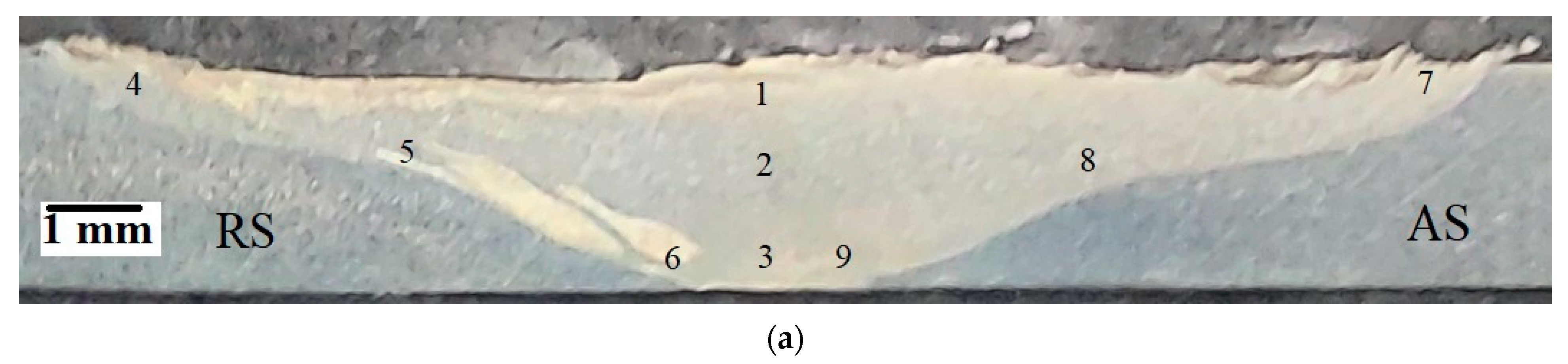
| Point | Microstructure |
|---|---|
| 1 | Twin structure |
| 2 | Twin structure |
| 3 | Equiaxed grains with an average size of 2–3 μm |
| 4 | Twin microstructure |
| 5 | Refined microstructure, grain size varies from submicron size to 1–2 microns, the grain boundaries are serrated to some extent |
| 6 | Refined microstructure, grain size varies from submicron size to 1–2 microns, the grain boundaries are serrated to some extent |
| 7 | Serrated grain boundaries |
| 8 | Twin structure |
| 9 | Equiaxed grains with an average size of 2–3 μm |
| Type | Average Yield Strength (MPa) | Yield Strength S.D. (MPa]) | Average UTS (MPa) | UTS S.D. (MPa) | Average Elongation (%) | Elongation S.D. (%) |
|---|---|---|---|---|---|---|
| PM | 325.4 | 27.4 | 504.6 | 10.8 | 37.6 | 4.8 |
| FSW’ed | 400.8 | 37.1 | 507.8 | 33.6 | 8.5 | 2.3 |
Disclaimer/Publisher’s Note: The statements, opinions and data contained in all publications are solely those of the individual author(s) and contributor(s) and not of MDPI and/or the editor(s). MDPI and/or the editor(s) disclaim responsibility for any injury to people or property resulting from any ideas, methods, instructions or products referred to in the content. |
© 2023 by the authors. Licensee MDPI, Basel, Switzerland. This article is an open access article distributed under the terms and conditions of the Creative Commons Attribution (CC BY) license (https://creativecommons.org/licenses/by/4.0/).
Share and Cite
Regev, M.; Almoznino, B.; Spigarelli, S. A Study of the Metallurgical and Mechanical Properties of Friction-Stir-Welded Pure Titanium. Metals 2023, 13, 524. https://doi.org/10.3390/met13030524
Regev M, Almoznino B, Spigarelli S. A Study of the Metallurgical and Mechanical Properties of Friction-Stir-Welded Pure Titanium. Metals. 2023; 13(3):524. https://doi.org/10.3390/met13030524
Chicago/Turabian StyleRegev, Michael, Benny Almoznino, and Stefano Spigarelli. 2023. "A Study of the Metallurgical and Mechanical Properties of Friction-Stir-Welded Pure Titanium" Metals 13, no. 3: 524. https://doi.org/10.3390/met13030524