Review

Twinning in Hexagonal Close-Packed Materials: The Role of Phase Transformation

Department of Mechanical Engineering, University of Nevada Reno, Reno, NV 89557, USA
*
Author to whom correspondence should be addressed.
Metals 2023, 13(3), 525; https://doi.org/10.3390/met13030525
Submission received: 31 January 2023 / Revised: 25 February 2023 / Accepted: 1 March 2023 / Published: 5 March 2023

Abstract

:
Twinning is a major mechanism of plastic deformation in hexagonal close-packed (hcp) structures. However, a mechanistic understanding of twin nucleation and growth has yet to be established. This paper reviews the recent progress in the understanding of twinning in hcp materials—particularly the newly discovered phase transformation-mediated twinning mechanisms—in terms of crystallographical analysis, theoretical mechanics calculations, and numerical simulations. Moreover, the relationship between phase transformation-mediated twinning mechanisms and twinning dislocations are presented, forming a unified understanding of deformation twinning. Finally, this paper also reviews the recent studies on transformation twins that are formed in hcp martensite microstructures after various phase transformations, highlighting the critical role of the mechanical loading in engineering a transformation twin microstructure.

1. Introduction

Due to a high strength-to-weight ratio and desirable bio-compatibility, metals and alloys with hexagonal close-packed (hcp) structures have been widely used in engineering applications, including automotive, aerospace, and biomedical industries [1]. In hcp materials, dislocation slip occurs in the basal, prismatic, first-order pyramidal, and second-order pyramidal planes (Table 1). Due to the low atomic packing density in the prismatic and pyramidal planes, slip systems containing the  c  component have a significantly higher critical resolved shear stress and become less active than the  a  slip [2]. To compensate for the insufficient number of active slip systems, deformation twinning emerges as another major deformation mechanism common in hcp materials. In contrast to the well-understood dislocation slip, twinning is less studied and there are still several twinning behaviors that are viewed as “anomalies” [3]. An improved understanding of twinning in hcp materials will likely lead to novel design strategies for advanced magnesium (Mg), titanium (Ti), and zirconium (Zr) alloys with enhanced mechanical properties. To stimulate wider research interests and efforts in twinning in hcp metals, this paper is dedicated to reviewing classical twinning theory and, moreover, the recent discoveries of transformation-mediated twin mechanisms.

2. Twinning in hcp Materials

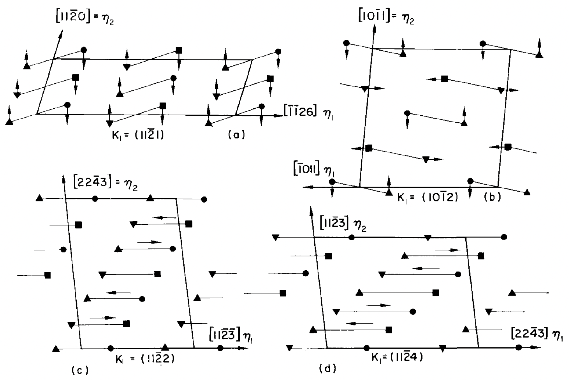
2.1. The Crystallography of Twinning

In response to an applied loading, part of the crystalline material undergoes an orientation rotation (i.e., a twin), forming a mirror symmetry relation with the original material (i.e., the parent) [4,5]. A twin and its parent remain in contact by a planar boundary, which is referred to as the twin boundary. Therefore, the deformation that converts the parent into a twin should be an invariant plane strain. This deformation is further narrowed down to a simple shear because the parent and its twin have the identical lattice structure [6]. Moreover, this twinning shear leaves two planes undistorted: the twinning plane ( K 1 ) remains unchanged, while the conjugate twinning plane (or the second undistorted plane,  K 2 ) merely undergoes a rotation. Crystallographically, the twin relation can be described by a set of twinning elements/parameters; namely, the direction of twinning shear ( η 1 ) in the twinning plane of  K 1 , the conjugate twinning direction ( η 2 ) in the conjugate twinning plane of  K 2 , and the twinning shear magnitude of s. As a common twinning mode in all the hcp materials, the  { 10 1 ¯ 2 }  twin is the most widely studied twinning mode. Its twinning elements are  K 1 = { 10 1 ¯ 2 } η 1 = 10 1 ¯ 1 ¯ K 2 = { 1 ¯ 012 } , and  η 2 = 1 ¯ 01 1 ¯ . The twinning shear depends on the  c / a  ratio of the hcp materials:  s = 0.126  for Mg and  s = 0.176  for Ti.
There are four common twinning modes in hcp structures, which are  { 10 1 ¯ 2 } { 10 1 ¯ 1 } { 11 2 ¯ 2 } , and  { 11 2 ¯ 1 }  twins. They are often classified into extension (tension) or contraction (compression) twins. Specifically, an extension twin is formed when the applied loading leads to an extension along the c-axis, while contraction twins are activated if the applied loading leads to a contraction along the c-axis. For example, the  { 10 1 ¯ 2 }  twin is often referred to as an extension twin and the  { 10 1 ¯ 1 }  is often called a contraction twin. However, it should be noted that this naming convention is specific to hcp metals whose c/a ratio is smaller than the theoretical number of 1.633, such as Mg, Ti, and Zr. In contrast, the  { 10 1 ¯ 2 }  twin is a contraction twin and the  { 10 1 ¯ 1 }  twin is an extension twin for hcp metals with c/ a >  1.633, such as zinc and cadmium.
Twinning has been widely interpreted as a simple shear deformation, which is true for high-symmetry face-centered cubic (fcc) structures. However, an often neglected fact is that atomic shuffle is an indispensable component to twinning, especially for low-symmetry hcp structures. The shear of the parent atoms can hardly lead to a perfect twin symmetry. Indeed, twinning is achieved by the shear of only certain atomic layers and shuffles of many other atomic layers [7]. For example, every third atomic layer in the  { 11 2 ¯ 2 }  twinning mode undergoes only shear, while the other two layers shuffle (Figure 1c). In contrast, all the atomic layers shuffle in the  { 10 1 ¯ 2 }  twinning mode (Figure 1b).
Besides the coherent portion, a twin boundary often contains dislocations, particularly at regions close to the twin tip. Such twinning dislocations are also referred to as disconnections [2,8,9], which have a Burgers vector and a step character with a certain height. For lattice dislocations, the Burgers vector is determined by drawing the Burgers circuit around its core and observing the closure failure. Similarly, the Burgers vector of disconnections could be obtained by drawing the Burgers circuit in the dichromatic complex pattern that superimposes parent and twin lattice sites [2]. It should be noted that the finding of the Burgers vector of a disconnection requires one translation vector for the parent and another translation vector for the twin. Disconnections can glide along the twin boundary in response to an applied loading, resulting in the migration of the twin boundary. At the atomistic level, the atomic movements inside the disconnection core produce both the shear and shuffles needed for the twinning mode [7]. It should be noted that annealing twins and deformation twins are two types of commonly observed twins in crystalline materials, both of which show mirror symmetry across the twin boundary. However, their formation mechanisms are distinctively different. The former is commonly known to form due to growth accidents during the recrystallisation of heavily deformed fcc metals, such as alpha-brass, copper, nickel and austenitic iron [10]. Therefore, the shape of the annealing twin is dictated by the minimization of the interfacial energy, leading to flat twin tips. In contrast, the deformation twins are formed by a shear deformation of the lattice and are common in both fcc and hcp materials. Due to the large twinning shear, the shape of the deformation twins is determined by the minimization of the elastic strain energy. Because the strain energy concentrates at the twin tips, deformation twins are usually lenticular shaped with sharp twin tips.

2.2. Deformation Twinning Models

So far, the twin formation in fcc and body-centered cubic (bcc) materials have been quite well-established, because twinning and lattice dislocations share the same planes. Twinning could be formed either by the reaction and dissociation of lattice dislocations [11,12,13,14] or by the interaction of lattice dislocations with a twin boundary [15]. For instance, Wang and Huang proposed a mechanism of twin formation from Shockley partial dislocations on non-neighboring glide planes, based on their molecular dynamics (MD) simulations of fcc copper. Marian et al. [13] conducted MD simulations for dislocation motion in bcc iron. At high strain rates, the dislocation motion became rough, stopped abruptly, and emitted a twin plate that immediately took over as the dominant mode of plastic deformation. In contrast, twinning in hcp materials adopts habit planes that are not known as the slip planes for lattice dislocations. Therefore, the twinning mechanism for hcp structure still remains elusive in spite of being heavily investigated.
Numerous models have been proposed for twin nucleation, which can be divided into homogeneous models and heterogeneous models. The homogeneous nucleation models have long been known and do not involve any defects such as dislocations or grain boundaries [16,17,18]. However, because of the extremely high-stress requirement for these models, heterogeneous models were proposed for nucleation at a more reasonable stress level assisted by the presence of defects [19,20,21,22,23]. For instance, Mendelson [20,21] proposed the non-planar dissociation of  a c + a , or  c  dislocations, resulting in the formation of one or more glissile twinning dislocations on the respective twin planes. Under a proper stress state and in a large-sized dissociation event, twinning dislocations could break away and propagate in the grain, leading to either the formation of twin nucleus or successive twin growth. Similarly, Capolungo et al. [23] proposed a model for non-planar dissociation of  a  slip in hcp materials, based on the free energy change for the dissociated configurations calculated using continuum linear elastic dislocation theory. Once nucleated, the twin nucleus starts to grow—it propagates in the  η 1  direction and thickens perpendicular to the  K 1  plane. Capolungo et al. [24] compared slip-independent and slip-assisted mechanisms and determined the former to be the principal mechanism for twin growth in single crystal Mg.
More recently, the advancement in materials modeling has led to significant progress in forming a mechanistic understanding of deformation twinning. For instance, Wang et al. [25,26] investigated the nucleation of the  { 10 1 ¯ 2 }  twin using density-functional theory calculations and MD simulations. They proposed a zonal-twinning mechanism where a stable twin nucleus is created by one partial dislocation and multiple twinning dislocations. For the  { 10 1 ¯ 1 }  twin, Ostapovets et al. [27] conducted a MD simulation and found that twin nucleation originated from the dissociation of an  a  dislocation into both twinning dislocations and partial stacking faults. Additionally, the  { 10 1 ¯ 2 }  twin in Mg was observed to nucleate at the basal-prismatic interface in both experiment and MD simulation by Zhou et al. [28]. In another study by Wang et al. [29], they used atomistic simulations to systematically investigate the twin nucleation from symmetric tilt grain boundaries. Among a wide range of tilt angles, they found twin nucleation was most likely to occur at grain boundaries with low misorientation angles, in agreement with the EBSD analysis of Mg.
Furthermore, MD simulations have been used extensively to investigate the mechanism of twin growth. Serra and Bacon conducted MD simulations and discovered detailed interface structures and twinning dislocations for the common twinning modes in hcp metals [30]. Later on, they simulated the reactions between a  { 10 1 ¯ 2 }  twin boundary and lattice dislocations in hcp Ti, which formed residual defects and twinning dislocation dipoles in adjacent twin planes [31,32]. Under shear stress, the lenticular twin could grow by the expansion of twinning dislocation loops [31]. More details can be found in Christian and Mahajan’s [5] comprehensive review of deformation twinning in numerous crystalline structures and Partridge’s [33] and Yoo et al.’s [34] focused reviews on the twinning in hcp metals. In addition, there are several review papers on fcc metals: the review on models for deformation, annealing, and growth twins by Mahajan [35]; the review of deformation twinning in nanocrystalline fcc metals by Zhu et al. [36]; and the recent review on deformation and growth twin in fcc metals by Beyerlein et al. [37]. In contrast, this review summarizes the recent progress made primarily in the phase transformation-mediated mechanisms for deformation twinning in hcp materials.
The aforementioned attempts to understand deformation twinning are largely based on lattice dislocations or interfacial dislocations at the twin boundary. More recently, interpretations of deformation twinning in a different perspective have emerged and generated significant new insights. Motivated by the similarity between twinning and phase transformation, Cayron adopted the hard-sphere assumption and proposed the displacive model for multiple twinning modes in hcp materials [3,38,39,40]. Notably, twinning deformation in this model has a volumetric component at the midpoint between the parent and the twin, and only recovers to a simple shear at the end of the twinning process. In a notable MD study by Li and Ma [41], shuffling-dominated lattice reconstruction was proposed for  { 10 1 ¯ 2 }  twinning, because of the larger magnitude of the shuffles compared to that of the twinning shear. However, Serra et al. [42] questioned the validity of this shuffling-dominated model because shuffles cannot accommodate plastic deformation. Subsequently, Li clarified that the macroscopic strain is accommodated by the misfit strain along the c-axis within this shuffling-dominated model [43].
In an experimental study of submicron-sized singlecrystal Mg,  { 10 1 ¯ 2 }  twinning is proposed to occur through basal-prismatic transformation, which converts the basal (prismatic) plane of the parent into the prismatic (basal) plane of the twin [44]. Note that the basal–prismatic transformation is a tetragonal deformation, and the terminology of “unit cell reconstruction” is also often used [45]. Later on, the difference between the tetragonal deformation and the twinning shear was found to be a small rotation of 3.7° that is accommodated by the disclinations formed between the basal–prismatic interface and the coherent  { 10 1 ¯ 2 }  twin boundary [46].
In 2020, He et al. [47] used in situ high-resolution transmission electron microscopy to capture the twin nucleation in hcp rhenium nanocrystals. They observed a dual-step twin nucleation mechanism for the  { 10 1 ¯ 2 }  twin: first, the nucleus is close to the twin’s lattice correspondence with a slight deviation from the ideal twin orientation; second, the minor deviation from the perfect twin is corrected by the rearrangement of disconnections on the prismatic–basal interface. Other two-step models have been proposed in recent theoretical work [48] and MD simulations [49]. Gao et al. theoretically derived all the twinning modes in hcp metals based on certain hcp–bcc–hcp phase transformation pathways [48]. Specifically, only the hcp–bcc–hcp induced  { 10 1 ¯ 2 }  twin was found to correspond to the deformation twinning mode in hcp materials. This has been verified in the MD simulation of Ti by Chen et al. [49]. For Mg, the MD simulations by Ombogo et al. [50] captured the dynamic process of hcp–bcc–hcp mediated  { 10 1 ¯ 2 }  twins. Moreover, the atomic movements during the process were traced and found to agree with those in twinning dislocations [50]. Besides the  { 10 1 ¯ 2 }  twin, Zahiri et al. [51] reported the formation of  { 11 2 ¯ 2 }  twins through reversible hcp– ω –hcp phase transformations. By comparing the twinning shear and shuffles, the hcp– ω –hcp mediated  { 11 2 ¯ 2 }  twins were found to correspond to the experimentally observed  { 11 2 ¯ 2 }  contraction twins in Ti.
The similarity between deformation twinning and phase transformation has long been recognized [3]. Therefore, it has been questioned if deformation twinning is indeed a phase transformation that occurs within the identical lattice structure. In the next section, we will first review the phase transformations in hcp materials, which is critical for understanding the newly proposed deformation twinning models based on reversible/two-step phase transformations. Afterwards, we will review another type of important twins—transformation twins that are abundant in martensite microstructures.

3. Phase Transformation-Mediated Deformation Twinning

3.1. Phase Transformation in hcp Structures

Considerable research efforts have been devoted to investigating phase transformations in hcp metals and alloys [52,53,54,55,56,57,58,59,60,61,62,63,64,65,66,67]. Particularly for hcp transition metals such as Ti and Zr, there exist several fascinating phase transformations. For each case, the transformation pathways and orientation relations will be reviewed to provide the background knowledge for phase transformation-mediated twinning mechanisms that will be discussed in Section 3.2.

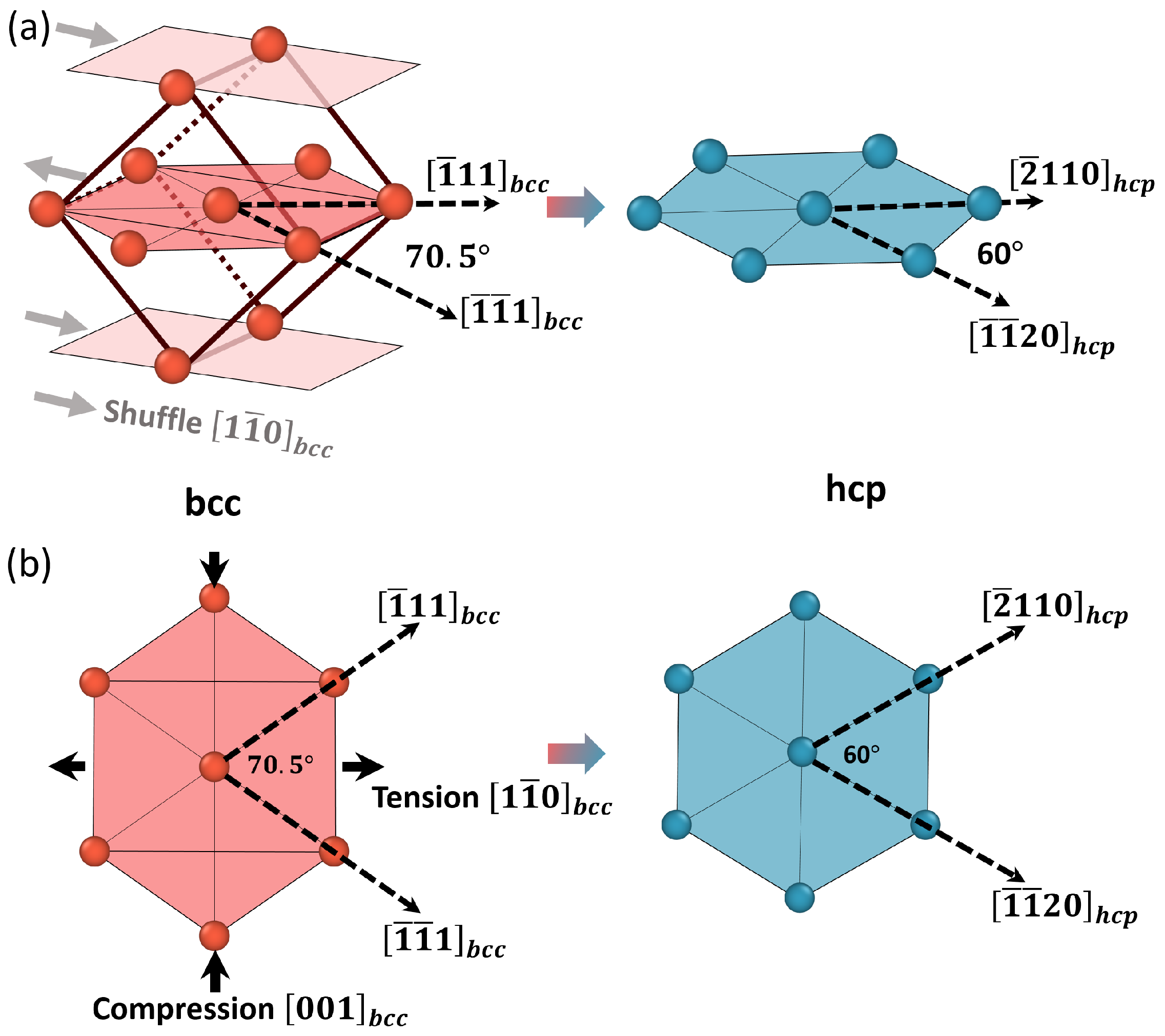
3.1.1. Bcc-hcp Transformation
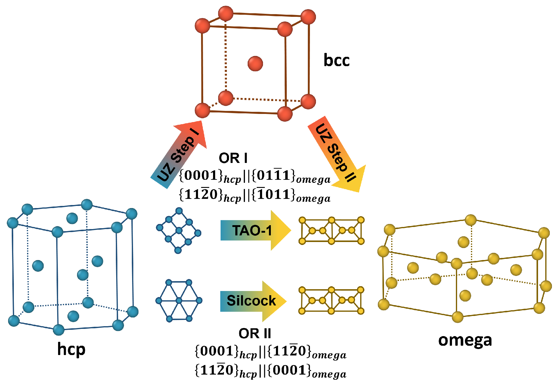
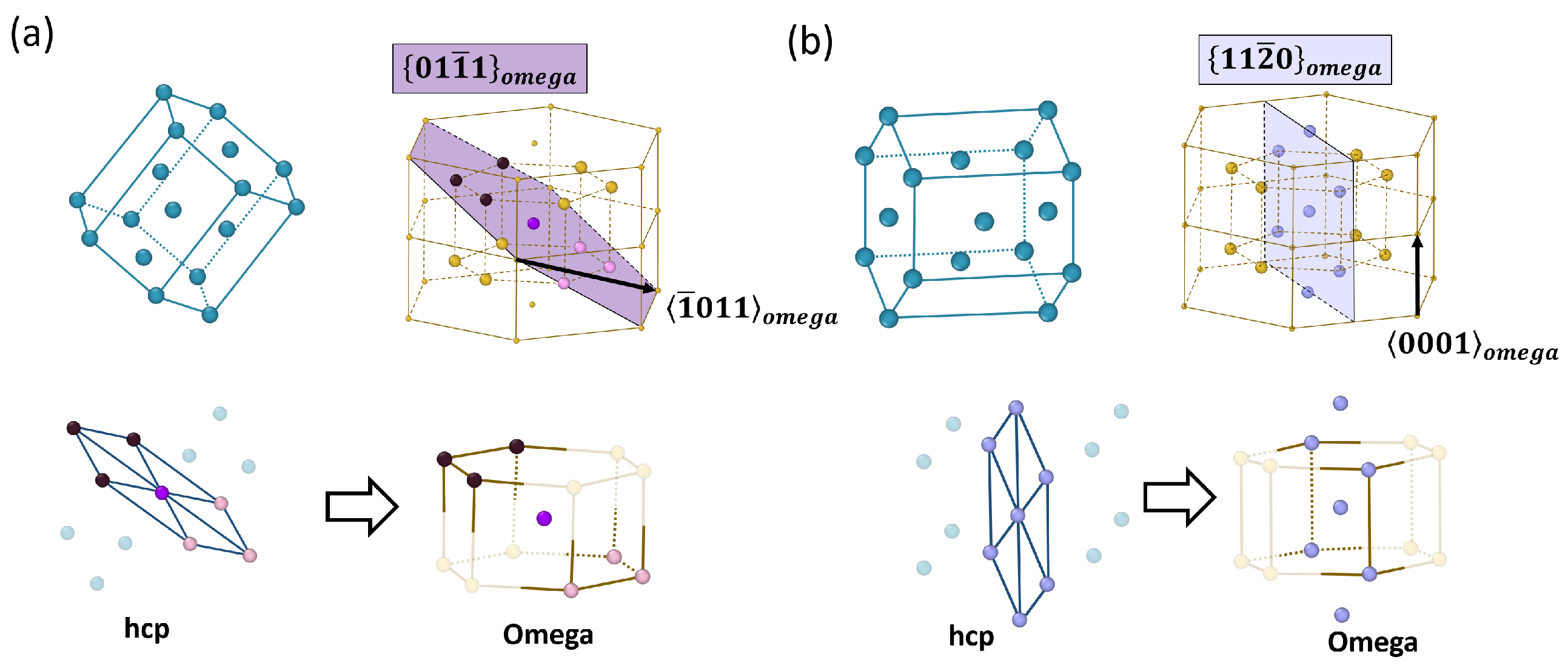
The phase transition between hcp and bcc structures is one of the most well-known solid–solid phase transitions [68,69,70,71]. Several transformation mechanisms have been reported, including the Burgers, Pitsch–Schrader (PS), Potter, and Rong–Dunlop mechanisms [69,72,73,74,75]. The most widely known Burgers mechanism contains a shear strain and shuffles in the  { 110 } b c c  planes. As shown in Figure 2b, the shear strain changes the  70 . 53 °  angle between two  111  directions in the  { 110 }  plane into the  60 °  angle between two  a  directions in the basal plane of the hcp structure [74]. In addition, the alternating shuffles of the  { 110 }  planes (Figure 2a) form the correct ABAB stacking sequence in the hcp structure, thus completing the transformation process. The resulting orientation relation (OR) is  ( 01 1 ¯ ) b c c ( 0001 ) h c p  and  [ 1 1 ¯ 1 ] b c c a . The PS mechanism shares the same plane correspondence of  ( 1 1 ¯ 0 ) b c c ( 0001 ) h c p , but a different direction correspondence of  [ 001 ] b c c a  [76,77,78]. The Potter mechanism has an OR close to that of the Burgers mechanism with a slight alteration: the newly transformed  ( 0001 ) h c p  plane rotates by  2 °  from the originating  ( 011 ) b c c  planes. Lastly, the Rong–Dunlop mechanism has a different plane correspondence of  ( 0001 ) h c p ( 021 ) b c c  and the direction correspondence of  [ 100 ] b c c a  [79].

3.1.2. Hcp- ω  Transformation

High pressure or shock loading can change the electronic bandstructure of hcp transition metals of Ti, Zr, and hafnium, thus stabilizing the metastable  ω -phase [56]. The  ω  phase has a simple hexagonal lattice with three atoms in the unit cell and belongs to the hexagonal P6/mmm space group. There are three major pathways for hcp- ω  phase transformation, two of which are direct transformations between the hcp and  ω  phases (known as the TAO-1 [80] and Silcock [81] pathways), while the third is a two-step process via an intermediate bcc phase (known as the UZ pathway [82]). Notably, the TAO-1 pathway was shown to be the most energetically favorable pathway [80]. The three pathways follow two orientation relations (OR), both of which have been observed experimentally [82,83,84,85,86,87]. As shown in Figure 3, TAO-1 and UZ pathways share the first OR (referred to as OR I), while the Silcock pathway follows the second OR (referred to as OR II).
In OR I, the basal plane of the hcp phase transforms into a corrugated  { 01 1 ¯ 1 } ω  plane [80]. As shown in Figure 4a, this  { 01 1 ¯ 1 } ω  plane consists of three black atoms from the top B plane of the  A l B 2  structure, one purple atom from the middle A plane, and three pink atoms from the bottom B plane. These seven atoms correspond to the hexagonal ring in the basal plane of the hcp phase. In OR II, the basal plane of the hcp phase transforms into a  { 11 2 ¯ 0 } ω  plane. As shown in Figure 4b, this  { 11 2 ¯ 0 } ω  plane consists four atoms in the B plane and three atoms from the A plane. The two orientation relationships are summarized in Equation (1).
OR I : ( 0001 ) h c p ( 01 1 ¯ 1 ) ω , [ 11 2 ¯ 0 ] h c p [ 1 ¯ 011 ] ω , OR II : ( 0001 ) h c p ( 11 2 ¯ 0 ) ω , [ 11 2 ¯ 0 ] h c p [ 0001 ] ω .

3.1.3. Hcp-fcc Transformation

The hcp–fcc phase transition can be induced by either mechanical deformation or temperature change [88] in hcp materials, such as Ti [89,90,91], Zr [92], cobalt [93,94], tantalum [95], MgTi [96], and TiZr [97]. It is commonly believed that the hcp–fcc phase transition occurs through the gliding of the Shockley partial dislocations on every other basal planes of the hcp structure, leading to the OR of  { 0001 } h c p { 111 } f c c  and  a h c p [ 110 ] f c c  [74]. Recently, a new OR of  { 10 1 ¯ 1 } h c p { 1 1 ¯ 0 } f c c  and  [ 0001 ] h c p [ 001 ] f c c , called the prismatic relation, is reported in pure bulk Ti under cryogenic plain–strain compression [91]. Moreover, the prismatic relationship was also observed in MD simulations of single-crystal Ti nanopillar under  c  tension and in experiments of polycrystalline Ti after rolling at room temperature [90]. Two mechanisms has been proposed for the prismatic relationship for hcp–fcc phase transformation. The first mechanism involves the gliding of a series of Shockley partial dislocations with a Burgers vector of  1 6 a  in  { 10 1 ¯ 1 }  planes [89,91]. The second mechanism involves the nucleation of fcc bands through pure-shuffle and the migration and growth of phase boundaries by the shear-shuffle process [90].

3.2. Deformation Twinning Models

After discussing the major phase transformations in hcp materials, we will review the recent studies on the phase transformation-mediated twin formation, which do not involve dislocations or grain boundaries and differ from the dislocation-based models discussed in Section 2.2. Specifically, the reported intermediate phase involved in the twinning process, the material system, and the twinning elements are summarized in Table 2.

3.2.1. Hcp–bcc–hcp Mediated Twinning

In a theoretical study of the deformation twinning in hcp Ti and Zr, Gao et al. [48] used a phase transition graph approach to determine the deformation path of various twinning modes that are related to the symmetry breaking associated with the bcc–hcp transformation. As shown in Figure 5a, each bcc phase is connected with six hcp phases, while each hcp phase is connected with three bcc phases. They calculated the deformation gradient for many possible reversible transformations to predict the complete twinning elements (Table 3), and to compare with the known deformation twinning modes in Ti and Zr. Among the hcp–bcc–hcp induced  { 10 1 ¯ 2 } { 10 1 ¯ 1 } { 11 2 ¯ 2 }  and  { 11 2 ¯ 1 }  twins, the  { 10 1 ¯ 2 }  twin is the only mode shared between the hcp–bcc–hcp induced twinning and the deformation twinning. It should be noted that the three other hcp–bcc–hcp induced twins are not listed in Table 2, because they do not correspond to the well-known deformation twinning modes in hcp materials.
Gao’s theoretical work provided a crystallographic foundation for the new deformation pathway that deformation twinning could occur through the reversible phase transformation. However, the validity of this new deformation pathway needs to be evaluated by simulations or experiments, in the perspective of energetics. In particular, MD simulations have made significant progress in the new deformation pathway of phase transformation-mediated twinning, which will be discussed next.
The MD simulations by Ombogo et al. captured the nucleation of the  { 10 1 ¯ 2 }  twin in Mg through a reversible hcp–bcc–hcp phase transformation process [50]. Figure 6 shows the snapshots of the deformation process, and the observed phase transformation-mediated twinning process is schematically shown in Figure 6h. Specifically, the intermediate phase involved in the twinning process was identified as a bcc structure by common neighbor analysis [98].
Ten different regions over many time steps in the MD simulation were selected to examine the intermediate phase. Further relaxation simulations were conducted and the distorted bcc phase was determined to be a tetragonal structure [50], of which the unit cell and the projection in various directions are shown in Figure 7. It should be noted that bcc/tetragonal phase does not appear in the equilibrium phase diagram of Mg, except that bcc Mg was predicted by first-principle calculations to be stable under high pressure [99]. The tetragonal structure observed here is a distorted bcc phase, which is expected to be stabilized by the local strain/stress.
In addition, the atomic motion was traced to compare the new phase transformation-mediated twinning mechanism [50] and the twinning dislocation mechanism [100]. The intermediate phase was found to correspond to the core of twinning dislocation. Given the high speed of martensitic phase transformation, this new twinning mechanism sheds light on the fast nucleation of the  { 10 1 ¯ 2 }  twins that are known to form under  10 4 s   [19].
A similar study on single crystal Ti was reported by Chen et al. [49]. As shown in Figure 8, their MD simulation revealed the transitory bcc phase during the nucleation of  { 10 1 ¯ 2 }  deformation twins in Ti. It should be noted that future MD simulations can be performed for other hcp materials such as Zr and cadmium to further verify the hcp–bcc–hcp deformation pathway for the  { 10 1 ¯ 2 }  deformation twin.

3.2.2. Hcp– ω –hcp Mediated Twinning

After discussing the hcp–bcc–hcp deformation pathway for the  { 10 1 ¯ 2 }  twins common in all the hcp materials, we will move on to the  { 11 2 ¯ 2 }  twins that are unique in Ti and Zr. Considering the fact that Ti and Zr share a unique high-pressure metastable  ω  phase, a potential hcp– ω –hcp deformation pathway could lead to the  { 11 2 ¯ 2 }  contraction twins observed in Ti and Zr. Its twinning elements are  K 1 = { 11 2 ¯ 2 } η 1 = 11 2 ¯ 3 ¯ K 2 = { 11 2 ¯ 4 ¯ } η 2 = 22 4 ¯ 3 ¯ , and a twinning shear of  s = 0.219  for Ti.
Zahiri et al. [51] confirmed the formation of  { 11 2 ¯ 2 }  contraction twins in Ti through the non-conventional hcp– ω –hcp phase transformation process. Figure 9 shows the MD simulations of deformation of a polycrystal Ti. It was observed that a perfect  { 11 2 ¯ 2 }  contraction twin can be formed by an initial transformation from the parent hcp phase into an intermediate  ω  phase, followed by the reverse transformation into a twinned hcp phase (Figure 9). Moreover, it was observed that a small amount of  ω  phase can still exist at the twin tip and coherent twin boundary, as highlighted in Figure 9c–f. Indeed, a recent atomic-resolution scanning transmission electron microscope image of the  { 11 2 ¯ 2 }  twin boundary showed dissociated interfacial structure [101], which is later analyzed and interpreted as a half  ω  unit cell [102]. Besides the portion along the invariant plane, it is expected that more  ω  region could be observed at the twin tip, which awaits experimental confirmation using high-resolution characterization techniques.
Furthermore, both the hcp– ω  and  ω –hcp transformation were found to follow the TAO-1 mechanism, which is known to be the energetically favorable pathway [80]. Moreover, it is known that multiple  { 11 2 ¯ 2 }  twinning modes exist [7,48,103]. For example, the hcp–bcc–hcp induced  { 11 2 ¯ 2 }  twins (Table 3) identified by Gao et al. were found to differ from the  { 11 2 ¯ 2 }  contraction twins (Table 2) observed experimentally in Ti and Zr. Therefore, the complete twinning elements need to be examined. As shown in Figure 10a, the conjugate twinning plane was traced in the MD simulation and identified as  K 2 = { 11 2 ¯ 4 ¯ } . A group of atoms were traced and their evolution demonstrated that this hcp– ω –hcp mediated twinning process shares the same net shear, shuffle, and  K 2  plane with the classical twinning theory. The proposed mechanism, emphasizing the evanescent intermediate state of the  ω  phase, revealed the dynamic deformation path and the physical origin of the  { 11 2 ¯ 2 }  contraction twins.

3.3. The Connection to Dislocation-Based Models

Significant new insights have been obtained in the new transformation-mediated twinning mechanisms for  { 10 1 ¯ 2 }  twins [48,49,50] and  { 11 2 ¯ 2 }  twins [51]. However, this new deformation path seems to be at odds with the more popular dislocation (disconnection)-based model [2,9,26] (Section 2.2). This conflict were nicely addressed by Ostapovets et al. [102] in the case of  { 11 2 ¯ 2 }  contraction twins. They demonstrated the consistency between the twinning disconnection and transformation-mediated mechanism: the twin growth is mediated by disconnections; and the disconnection core is an  ω  phase. In other words, the reversible phase transformation occurs inside the core of disconnections during twin growth. As shown in Figure 11a,b, they observed a half  ω  unit cell inside the dissociated disconnections whose net Burgers vector agrees with the  b 3 / 3  disconnections reported in a previous study [30]. Moreover, by comparing the interatomic potentials used by Li et al. [101] with those by Zahiri et al. [51], they emphasized the critical role of the  ω  phase stability in the activation of the correct  { 11 2 ¯ 2 }  contraction twins. Besides the  { 11 2 ¯ 2 }  twin, the relation between the phase transformation-mediated mechanism and twinning disconnection calls for future research efforts for other twinning modes such as the  { 10 1 ¯ 2 }  and  { 10 1 ¯ 1 }  twins.

4. Transformation Twins

Twin interfaces are often observed in martensite microstructure. In the theories of martensite crystallography, these twins are caused by an additional twinning shear that accompanies the lattice change to complete the phase transformation. These theories are successful in predicting and rationalizing the experimentally observed habit planes. In contrast, there exists a different interpretation on twinning in martensite microstructure. In particular, the two twinned product phases form directly from the parent phase by means of crystallographically equivalent correspondences [104,105], and the terminology of transformation twins is suggested for twins formed after phase transformation [48,49,50,55,106].
Furthermore, the formation process of transformation twins and the new phase transformation-mediated twins share plenty of similarities. Taking the high temperature bcc phase as an example, the transformation twin is formed between hcp1 and hcp2 that originate from the same parent bcc phase (hcp1←bcc→hcp2). In contrast, the phase transformation-mediated deformation twin is formed between hcp1 and hcp2 through an intermediate bcc phase (hcp1→bcc→hcp2). Therefore, the crystallography, deformation gradient, and twinning elements are identical for transformation twins and deformation twins. In contrast, the driving force of the former is quenching, while that of the latter is mechanical loading.

4.1. Bcc-hcp Transformation Twins

Bcc–hcp phase transformations can be induced by high pressure in iron [107,108] or quenching the high temperature bcc phase of Ti [109] and Zr [110]. Several variants could be activated during this martensitic phase transformation and complex twin structures could be formed [111]. Zahiri et al. [112] reported the effect of mechanical loading on the variant selection and twin formation during bcc–hcp phase transformation in Ti polycrystals. As shown in Figure 12a, under x-tension, the bcc phase transforms into two equivalent hcp variants following the Burgers mechanism [74],  { 110 } b c c { 0001 } h c p  and  [ 1 1 ¯ 1 ] b c c [ 11 2 ¯ 0 ] h c p  (introduced in Section 3.1.1), leading to the formation of a  { 10 1 ¯ 1 }  transformation twin. In contrast, when applying an opposite loading (x-compression), the bcc phase transforms into two equivalent hcp variants following the PS mechanism,  { 110 } b c c ( 0001 ) h c p  and  [ 001 ] b c c [ 2 1 ¯ 1 ¯ 0 ] h c p  (introduced in Section 3.1.1), leading to the formation of a  { 10 1 ¯ 2 }  transformation twin in the same grain (Figure 12b). In addition, some of the grains in the bcc polycrystal contain initial  { 112 }  twins. As shown in Figure 12c,d, the  { 112 }  twin will be transformed to a  { 11 2 ¯ 2 }  transformation twin under x-tension, and to a  { 11 2 ¯ 1 }  transformation twin under x-compression. Moreover, the loading direction dependence observed in the MD simulations was ascribed to the deformation gradient of each transformation twinning mode, which reveals the essential role of mechanical loading in the activation of the specific transformation twinning mode.
Finally, theoretical calculations of the complete twinning elements are conducted to compare the four transformation twins with deformation twins in hcp materials. These elements are the solution of the twinning equation [113,114]
R · U I U J = a n .
U I  and  U J  are the right stretch tensors of the parent and twin (calculated from the deformation gradients).  R  captures the twin misorientation and  n  is the normal for the twinning plane K. Finally, the direction of shear  η  and shear magnitude s are calculated as
η = a | a | , s = | a | | U J 1 · n | .
As shown in Table 4, only the  { 10 1 ¯ 2 }  transformation twin resembles the well-known  { 10 1 ¯ 2 }  deformation twin, which is in agreement with the theoretical calculation by Gao et al. [48].

4.2. ω -hcp Transformation Twins

Besides the high-temperature bcc phase, Ti and Zr have another high-pressure metastable phase, the  ω -phase. Upon the release of high pressure or heating to around 150 °C, the metastable  ω -phase transforms back to the thermodynamically stable hcp-phase, resulting in the formation of transformation twins [57,58,115]. For example, the  ω –hcp martensitic phase transformation in pure Ti was found to form  { 10 1 ¯ 1 }  twins [60]. For the stress-induced  ω -hcp martensitic transformation, the MD simulations by Zahiri et al. [55] showed that different types of transformation twins can be formed under mechanical loading in different directions. Figure 13 shows the formation of  { 10 1 ¯ 2 } { 10 1 ¯ 1 } { 11 2 ¯ 2 } , and  { 11 2 ¯ 1 }  transformation twins after  ω -hcp phase transformation.
As discussed in Section 3.1.2, the  ω –hcp phase transformation has two orientation relations (OR), OR I and OR II. Figure 13a,b show the formation of  { 11 2 ¯ 2 }  twin through two separate OR I phase transformation in two equivalent  { 01 1 ¯ 1 } ω  planes sharing a common  11 2 ¯ 0 ω  axis. Likewise, a  { 11 2 ¯ 1 }  twin can be formed through two separate OR I, as schematically shown in Figure 13c. In this case, the two equivalent  { 01 1 ¯ 1 } ω  planes share a common  11 2 ¯ 3 ω  axis, which differs from the previous case of a  { 11 2 ¯ 2 }  twin. On the other hand, an OR I on the  { 01 1 ¯ 1 } ω  plane and an OR II on the  { 11 2 ¯ 0 } ω  plane (Figure 13e) can form a  { 10 1 ¯ 2 }  twin (Figure 13f). Similarly, mixed OR I and OR II sharing a common  11 2 ¯ 3 ω  axis (Figure 13g) can lead to the formation of a  { 10 1 ¯ 1 }  twin (Figure 13h). Moreover, the MD simulations reveal that a three-fold  { 10 1 ¯ 1 }  (Figure 13j) twin can also form through two separate OR I and one OR II (Figure 13i).
The  ω –hcp phase transformation can lead to the formation of a maximum of nine hcp ( α ) variants. Zahiri et al. observed seven of them ( α 1 α 7 ) under the six loading directions applied in the MD simulations. As shown in Figure 14 α 1  and  α 2  form the  { 11 2 ¯ 2 } α  twin;  α 1  and  α 3  form the  { 11 2 ¯ 1 } α  twin;  α 1  and  α 4  form the  { 10 1 ¯ 2 } α  twin;  α 4 α 5 , and  α 6  form the threefold  { 10 1 ¯ 1 } α  twin; and  α 5  and  α 7  form the  { 10 1 ¯ 1 } α  twin. The results revealed the role of mechanical loading in twin selection and the variety and complexity of transformation twins in hcp structure, shedding light on the microstructure analysis of shock recovered Ti/Zr metals and alloys.

5. Conclusions

In summary, the recent progress in the understanding of twinning in hcp materials—particularly the newly discovered phase transformation-mediated twinning mechanisms—are reviewed in terms of the crystallographical analysis, theoretical mechanics calculations, numerical simulations. Specifically, the hcp-bcc-hcp transformation pathway forms  { 10 1 ¯ 2 } 01 1 ¯ 1  deformation twins ( s = 0.126  for Mg), a common twinning mode in all hcp materials, while the hcp- ω -hcp transformation pathway forms  { 11 2 ¯ 2 } 11 2 ¯ 3 ¯  contraction twins ( s = 0.219  for Ti), a deformation twinning mode unique in hcp Ti and Zr. This twinning process not only agrees with the classical twinning theory, but also reveals the critical role of the intermediate phase and uncovers the physical origin of deformation twinning. Moreover, the consistency between the phase transformation-mediated twinning and twinning disconnections is presented for  { 11 2 ¯ 2 }  twins, forming a unified understanding of deformation twinning. During twin growth, the intermediate  ω  phase exists inside the dissociated core of twinning disconnections. In other words, the reversible phase transformation occurs inside the disconnection cores. Finally, the recent studies on transformation twins are also reviewed, considering their similarity to the phase transformation-mediated twinning process. The stress-induced bcc–hcp or  ω –hcp phase transformations are found to induce a variety of transformation twins in the final hcp structure. Moreover, the mechanical loading is found to play an essential role in the selection of the specific transformation twin, which can offer a novel strategy for engineering twin microstructures using designed thermomechanical processing.

Author Contributions

Writing—original draft preparation, A.H.Z., J.O. and M.L.; writing—review and editing, L.C.; funding acquisition, L.C. All authors have read and agreed to the published version of the manuscript.

Funding

The authors acknowledge the financial support from NSF OIA-Office of Integrative Activities (OIA-2132224), NSF CBET Thermal Transport Process Program (CBET-1953300), and NSF CMMI Mechanics of Materials and Structures Program (CMMI-1727428).

Data Availability Statement

The data that support the findings of this study are available from the corresponding author upon reasonable request.

Conflicts of Interest

The authors declare no conflict of interest.

References

  1. Britton, T.; Dunne, F.; Wilkinson, A. On the mechanistic basis of deformation at the microscale in hexagonal close-packed metals. Proc. R. Soc. A Math. Phys. Eng. Sci. 2015, 471, 20140881. [Google Scholar] [CrossRef] [Green Version]
  2. Ostapovets, A.; Serra, A. Review of non-classical features of deformation twinning in hcp metals and their description by disconnection mechanisms. Metals 2020, 10, 1134. [Google Scholar] [CrossRef]
  3. Cayron, C. Shifting the Shear Paradigm in the Crystallographic Models of Displacive Transformations in Metals and Alloys. Crystals 2018, 8, 181. [Google Scholar] [CrossRef] [Green Version]
  4. Christian, J.W. The Theory of Transformations in Metals and Alloys; Newnes: New South Wales, Australia, 2002. [Google Scholar]
  5. Christian, J.W.; Mahajan, S. Deformation twinning. Prog. Mater. Sci. 1995, 39, 1–157. [Google Scholar] [CrossRef]
  6. Mahajan, S.; Williams, D. Deformation twinning in metals and alloys. Int. Metall. Rev. 1973, 18, 43–61. [Google Scholar] [CrossRef]
  7. Crocker, A.; Bevis, M. The crystallography of deformation twinning in titanium. In The Science, Technology and Application of Titanium; Elsevier: Amsterdam, The Netherlands, 1970; pp. 453–458. [Google Scholar]
  8. Nabarro, F.R.; Duesbery, M.S. Dislocations in Solids; Elsevier: Amsterdam, The Netherlands, 2002. [Google Scholar]
  9. Hirth, J. Dislocations, steps and disconnections at interfaces. J. Phys. Chem. Solids 1994, 55, 985–989. [Google Scholar] [CrossRef]
  10. Cahn, R.W.; Haasen, P. Physical Metallurgy; Elsevier: Amsterdam, The Netherlands, 1996; Volume 1. [Google Scholar]
  11. Wang, J.; Huang, H. Shockley partial dislocations to twin: Another formation mechanism and generic driving force. Appl. Phys. Lett. 2004, 85, 5983–5985. [Google Scholar] [CrossRef]
  12. Narayan, J.; Zhu, Y. Self-thickening, cross-slip deformation twinning model. Appl. Phys. Lett. 2008, 92, 151908. [Google Scholar] [CrossRef] [Green Version]
  13. Marian, J.; Cai, W.; Bulatov, V.V. Dynamic transitions from smooth to rough to twinning in dislocation motion. Nat. Mater. 2004, 3, 158–163. [Google Scholar] [CrossRef]
  14. Fourie, J.; Weinberg, F.; Boswell, F. The growth of twins in tin single crystals as observed by transmission electron microscopy. Acta Metall. 1960, 8, 851–863. [Google Scholar] [CrossRef]
  15. Kvashin, N.; García-Müller, P.L.; Anento, N.; Serra, A. Atomic processes of shear-coupled migration in {112} twins and vicinal grain boundaries in bcc-Fe. Phys. Rev. Mater. 2020, 4, 073604. [Google Scholar] [CrossRef]
  16. Orowan, E. Dislocations in Metals; AIME: New York, NY, USA, 1954; Volume 131. [Google Scholar]
  17. Lee, J.; Yoo, M. Elastic strain energy of deformation twinning in tetragonal crystals. Metall. Trans. A 1990, 21, 2521–2530. [Google Scholar] [CrossRef]
  18. Yoo, M.; Lee, J. Deformation twinning in hcp metals and alloys. Philos. Mag. A 1991, 63, 987–1000. [Google Scholar] [CrossRef]
  19. Thompson, N.; Millard, D.J. Twin formation in cadmium. Lond. Edinb. Dublin Philos. Mag. J. Sci. 1952, 43, 422–440. [Google Scholar] [CrossRef]
  20. Mendelson, S. Zonal dislocations and twin lamellae in hcp metals. Mater. Sci. Eng. 1969, 4, 231–242. [Google Scholar] [CrossRef]
  21. Mendelson, S. Dislocation dissociations in hcp metals. J. Appl. Phys. 1970, 41, 1893–1910. [Google Scholar] [CrossRef]
  22. Vaidya, S.; Mahajan, S. Accommodation and formation of  { 11 2 ¯ 1 }  twins in Co single crystals. Acta Metall. 1980, 28, 1123–1131. [Google Scholar] [CrossRef]
  23. Capolungo, L.; Beyerlein, I. Nucleation and stability of twins in hcp metals. Phys. Rev. B 2008, 78, 024117. [Google Scholar] [CrossRef]
  24. Capolungo, L.; Beyerlein, I.; Tomé, C. Slip-assisted twin growth in hexagonal close-packed metals. Scr. Mater. 2009, 60, 32–35. [Google Scholar] [CrossRef]
  25. Wang, J.; Hoagland, R.; Hirth, J.; Capolungo, L.; Beyerlein, I.; Tomé, C. Nucleation of a  ( 1 ¯ 012 )  twin in hexagonal close-packed crystals. Scr. Mater. 2009, 61, 903–906. [Google Scholar] [CrossRef]
  26. Wang, J.; Hirth, J.; Tomé, C.   ( 1 ¯ 012 )  Twinning nucleation mechanisms in hexagonal-close-packed crystals. Acta Mater. 2009, 57, 5521–5530. [Google Scholar] [CrossRef]
  27. Ostapovets, A.; Serra, A. Slip dislocation and twin nucleation mechanisms in hcp metals. J. Mater. Sci. 2017, 52, 533–540. [Google Scholar] [CrossRef] [Green Version]
  28. Zhou, N.; Zhang, G.; Guo, T.F.; Guo, X.; Tang, S.; Huang, X. Twin nucleation at prismatic/basal boundary in hexagonal close-packed metals. Philos. Mag. 2019, 99, 2584–2603. [Google Scholar] [CrossRef]
  29. Wang, J.; Beyerlein, I.; Tomé, C. An atomic and probabilistic perspective on twin nucleation in Mg. Scr. Mater. 2010, 63, 741–746. [Google Scholar] [CrossRef]
  30. Serra, A.; Pond, R.C.; Bacon, D.J. Computer simulation of the structure and mobility of twinning disclocations in H.C.P. Metals. Acta Metall. et Mater. 1991, 39, 1469–1480. [Google Scholar] [CrossRef]
  31. Serra, A.; Bacon, D. A new model for {1012} twin growth in hcp metals. Philos. Mag. A 1996, 73, 333–343. [Google Scholar] [CrossRef]
  32. Serra, A.; Bacon, D.; Pond, R. Dislocations in interfaces in the hcp metals—I. Defects formed by absorption of crystal dislocations. Acta Mater. 1999, 47, 1425–1439. [Google Scholar] [CrossRef]
  33. Partridge, P. The crystallography and deformation modes of hexagonal close-packed metals. Metall. Rev. 1967, 12, 169–194. [Google Scholar] [CrossRef]
  34. Yoo, M.; Morris, J.; Ho, K.; Agnew, S. Nonbasal deformation modes of HCP metals and alloys: Role of dislocation source and mobility. Metall. Mater. Trans. A 2002, 33, 813–822. [Google Scholar] [CrossRef]
  35. Mahajan, S. Critique of mechanisms of formation of deformation, annealing and growth twins: Face-centered cubic metals and alloys. Scr. Mater. 2013, 68, 95–99. [Google Scholar] [CrossRef]
  36. Zhu, Y.; Narayan, J.; Hirth, J.; Mahajan, S.; Wu, X.; Liao, X. Formation of single and multiple deformation twins in nanocrystalline fcc metals. Acta Mater. 2009, 57, 3763–3770. [Google Scholar] [CrossRef]
  37. Beyerlein, I.J.; Zhang, X.; Misra, A. Growth twins and deformation twins in metals. Annu. Rev. Mater. Res. 2014, 44, 329–363. [Google Scholar] [CrossRef]
  38. Cayron, C. A one-step mechanism for new twinning modes in magnesium and titanium alloys modelled by the obliquity correction of a (58, a + 2b) prototype stretch twin. Acta Crystallogr. Sect. A Found. Adv. 2018, 74, 44–53. [Google Scholar] [CrossRef] [PubMed] [Green Version]
  39. Cayron, C. Hard-sphere displacive model of deformation twinning in hexagonal close-packed metals. Revisiting the case of the (56°, a) contraction twins in magnesium. Acta Crystallogr. Sect. A Found. Adv. 2017, 73, 346–356. [Google Scholar] [CrossRef] [Green Version]
  40. Cayron, C. Hard-sphere displacive model of extension twinning in magnesium. Mater. Des. 2017, 119, 361–375. [Google Scholar] [CrossRef] [Green Version]
  41. Li, B.; Ma, E. Atomic shuffling dominated mechanism for deformation twinning in magnesium. Phys. Rev. Lett. 2009, 103, 035503. [Google Scholar] [CrossRef]
  42. Serra, A.; Bacon, D.; Pond, R. Comment on “atomic shuffling dominated mechanism for deformation twinning in magnesium”. Phys. Rev. Lett. 2010, 104, 029603. [Google Scholar] [CrossRef]
  43. Li, B.; Zhang, X. Global strain generated by shuffling-dominated  { 10 1 ¯ 2 } 10 1 ¯ 1 ¯  twinning. Scr. Mater. 2014, 71, 45–48. [Google Scholar] [CrossRef]
  44. Liu, B.Y.; Wang, J.; Li, B.; Lu, L.; Zhang, X.Y.; Shan, Z.W.; Li, J.; Jia, C.L.; Sun, J.; Ma, E. Twinning-like lattice reorientation without a crystallographic twinning plane. Nat. Commun. 2014, 5, 1–6. [Google Scholar] [CrossRef] [Green Version]
  45. Liu, B.Y.; Wan, L.; Wang, J.; Ma, E.; Shan, Z.W. Terrace-like morphology of the boundary created through basal-prismatic transformation in magnesium. Scr. Mater. 2015, 100, 86–89. [Google Scholar] [CrossRef] [Green Version]
  46. Ostapovets, A.; Buršík, J.; Gröger, R. Deformation due to migration of faceted  { 10 1 ¯ 2 }  twin boundaries in magnesium and cobalt. Philos. Mag. 2015, 95, 4106–4117. [Google Scholar] [CrossRef]
  47. He, Y.; Li, B.; Wang, C.; Mao, S.X. Direct observation of dual-step twinning nucleation in hexagonal close-packed crystals. Nat. Commun. 2020, 11, 1–8. [Google Scholar] [CrossRef] [PubMed]
  48. Gao, Y.; Ke, J.H.; Mao, B.; Liao, Y.; Zheng, Y.; Aagesen, L.K. Twinning path determined by broken symmetry: A revisit to deformation twinning in hexagonal close-packed titanium and zirconium. Phys. Rev. Mater. 2020, 4, 070601. [Google Scholar] [CrossRef]
  49. Chen, P.; Wang, F.; Li, B. Transitory phase transformations during  { 10 1 ¯ 2 }  twinning in titanium. Acta Mater. 2019, 171, 65–78. [Google Scholar] [CrossRef]
  50. Ombogo, J.; Zahiri, A.H.; Ma, T.; Cao, L. Nucleation of  { 10 1 ¯ 2 }  Twins in Magnesium through Reversible Martensitic Phase Transformation. Metals 2020, 10, 1030. [Google Scholar] [CrossRef]
  51. Zahiri, A.H.; Ombogo, J.; Cao, L. Formation of  { 11 2 ¯ 2 }  contraction twins in titanium through reversible martensitic phase transformation. Scr. Mater. 2021, 195, 113694. [Google Scholar] [CrossRef]
  52. Seward, G.G.; Celotto, S.; Prior, D.J.; Wheeler, J.; Pond, R.C. In situ SEM-EBSD observations of the hcp to bcc phase transformation in commercially pure titanium. Acta Mater. 2004, 52, 821–832. [Google Scholar] [CrossRef]
  53. Daymond, M.R.; Holt, R.A.; Cai, S.; Mosbrucker, P.; Vogel, S.C. Texture inheritance and variant selection through an hcp–bcc–hcp phase transformation. Acta Mater. 2010, 58, 4053–4066. [Google Scholar] [CrossRef]
  54. Ghosh, P.S.; Arya, A.; Tewari, R.; Dey, G.K. Alpha to omega martensitic phase transformation pathways in pure Zr. J. Alloys Compd. 2014, 586, 693–698. [Google Scholar] [CrossRef]
  55. Zahiri, A.H.; Ombogo, J.; Ma, T.; Chakraborty, P.; Cao, L. Transformation-induced plasticity in omega titanium. J. Appl. Phys. 2021, 129, 015105. [Google Scholar] [CrossRef]
  56. Sikka, S.; Vohra, Y.; Chidambaram, R. Omega phase in materials. Prog. Mater. Sci. 1982, 27, 245–310. [Google Scholar] [CrossRef]
  57. Hammond, C.; Kelly, P. The crystallography of titanium alloy martensites. Acta Metall. 1969, 17, 869–882. [Google Scholar] [CrossRef]
  58. Nishiyama, Z.; Oka, M.; Nakagawa, H. { 10 1 ¯ 1 }  Transformation Twins in Titanium. Trans. Jpn. Inst. Met. 1966, 7, 174–177. [Google Scholar] [CrossRef] [Green Version]
  59. Frost, P.; Parris, W.; Hirsch, L.; Doig, J.; Schwartz, C. Isothermal transformation of titanium-chromium alloys. Trans. Asm 1954, 46, 231–256. [Google Scholar]
  60. Zong, H.; Xue, D.; Ding, X.; Lookman, T. Phase transformations in Titanium: Anisotropic deformation of ω phase. Proc. J. Phys. Conf. Ser. 2014, 500, 112042. [Google Scholar] [CrossRef] [Green Version]
  61. Williams, J.; Hickman, B.; Marcus, H. The effect of omega phase on the mechanical properties of titanium alloys. Metall. Trans. 1971, 2, 1913–1919. [Google Scholar] [CrossRef]
  62. Brotzen, F.R.; Harmon, E.L.; Troiano, A.R. Decomposition of beta titanium. JOM 1955, 7, 413–419. [Google Scholar] [CrossRef]
  63. Hickman, B. The formation of omega phase in titanium and zirconium alloys: A review. J. Mater. Sci. 1969, 4, 554–563. [Google Scholar] [CrossRef]
  64. Kumar, A.; Bronkhorst, C.A.; Lookman, T. First-principles study of the α-ω phase transformation in Ti and Zr coupled to slip modes. J. Appl. Phys. 2018, 123, 045903. [Google Scholar] [CrossRef]
  65. Tane, M.; Okuda, Y.; Todaka, Y.; Ogi, H.; Nagakubo, A. Elastic properties of single-crystalline ω phase in titanium. Acta Mater. 2013, 61, 7543–7554. [Google Scholar] [CrossRef]
  66. Adachi, N.; Todaka, Y.; Irie, K.; Umemoto, M. Phase transformation kinetics of ω-phase in pure Ti formed by high-pressure torsion. J. Mater. Sci. 2016, 51, 2608–2615. [Google Scholar] [CrossRef]
  67. Todaka, Y.; Sasaki, J.; Moto, T.; Umemoto, M. Bulk submicrocrystalline ω-Ti produced by high-pressure torsion straining. Scr. Mater. 2008, 59, 615–618. [Google Scholar] [CrossRef]
  68. Gaunt, P.; Christian, J. The crystallography of the β-α transformation in zirconium and in two titanium-molybdenum alloys. Acta Metall. 1959, 7, 534–543. [Google Scholar] [CrossRef]
  69. Van Bohemen, S.M.C.; Sietsma, J.; Van der Zwaag, S. Experimental observations elucidating the mechanisms of structural bcc-hcp transformations in β-Ti alloys. Phys. Rev. B 2006, 74, 134114. [Google Scholar] [CrossRef] [Green Version]
  70. Lonardelli, I.; Gey, N.; Wenk, H.R.; Humbert, M.; Vogel, S.; Lutterotti, L. In situ observation of texture evolution during αβ and βα phase transformations in titanium alloys investigated by neutron diffraction. Acta Mater. 2007, 55, 5718–5727. [Google Scholar] [CrossRef]
  71. Baruffi, C.; Finel, A.; Le Bouar, Y.; Bacroix, B.; Salman, O.U. Atomistic simulation of martensite microstructural evolution during temperature driven βα transition in pure titanium. Comput. Mater. Sci. 2022, 203, 111057. [Google Scholar] [CrossRef]
  72. Cayron, C.; Barcelo, F.; de Carlan, Y. The mechanisms of the fcc–bcc martensitic transformation revealed by pole figures. Acta Mater. 2010, 58, 1395–1402. [Google Scholar] [CrossRef]
  73. Zong, H.; He, P.; Ding, X.; Ackland, G.J. Nucleation mechanism for hcp→ bcc phase transformation in shock-compressed Zr. Phys. Rev. B 2020, 101, 144105. [Google Scholar] [CrossRef]
  74. Burgers, W. On the process of transition of the cubic-body-centered modification into the hexagonal-close-packed modification of zirconium. Physica 1934, 1, 561–586. [Google Scholar] [CrossRef]
  75. Pitsch, W.; Schrader, A. Die Ausscheidungsform des ϵ-Karbids im Ferrit und im Martensit beim Anlassen. Arch. Für Das Eisenhüttenwesen 1958, 29, 715–721. [Google Scholar] [CrossRef]
  76. Kante, S.; Leineweber, A. Two-phase and three-phase crystallographic relationships in white-solidified and nitrided Fe-C-Si cast iron. Acta Mater. 2019, 170, 240–252. [Google Scholar] [CrossRef]
  77. Ribis, J.; Doriot, S.; Onimus, F. Shape, orientation relationships and interface structure of beta-Nb nano-particles in neutron irradiated zirconium alloy. J. Nucl. Mater. 2018, 511, 18–29. [Google Scholar] [CrossRef] [Green Version]
  78. Zhou, J.P.; Zhao, D.S.; Zheng, O.; Wang, J.B.; Xiong, D.X.; Sun, Z.F.; Gui, J.N.; Wang, R.H. High-resolution electron microscopy observations of continuous precipitates with Pitsch-Schrader orientation relationship in an Mg–Al based alloy and interpretation with the O-lattice theory. Micron 2009, 40, 906–910. [Google Scholar] [CrossRef]
  79. Merkel, S.; Lincot, A.; Petitgirard, S. Microstructural effects and mechanism of bcc-hcp-bcc transformations in polycrystalline iron. Phys. Rev. B 2020, 102, 104103. [Google Scholar] [CrossRef]
  80. Trinkle, D.; Hennig, R.; Srinivasan, S.; Hatch, D.; Jones, M.; Stokes, H.; Albers, R.; Wilkins, J. New mechanism for the α to ω martensitic transformation in pure titanium. Phys. Rev. Lett. 2003, 91, 025701. [Google Scholar] [CrossRef] [Green Version]
  81. Silcock, J. An X-ray examination of the to phase in TiV, TiMo and TiCr alloys. Acta Metall. 1958, 6, 481–493. [Google Scholar] [CrossRef]
  82. Usikov, M.P.; Zilbershtein, V.A. The orientation relationship between the α- and ω-phases of titanium and zirconium. Phys. Status Solidi (a) 1973, 19, 53–58. [Google Scholar] [CrossRef]
  83. Sargent, G.; Conrad, H. Formation of the omega phase in titanium by hydrostatic pressure soaking. Mater. Sci. Eng. 1971, 7, 220–223. [Google Scholar] [CrossRef]
  84. Kilmametov, A.R.; Ivanisenko, Y.; Straumal, B.B.; Gornakova, A.S.; Mazilkin, A.A.; Hahn, H. The αω transformation in titanium-cobalt alloys under high-pressure torsion. Metals 2018, 8, 1. [Google Scholar] [CrossRef] [Green Version]
  85. Song, S.; Gray III, G. Microscopic and crystallographic aspects of retained omega phase in shock-loaded zirconium and its formation mechanism. Philos. Mag. A 1995, 71, 275–290. [Google Scholar] [CrossRef]
  86. Vohra, Y.; Sikka, S.; Menon, E.; Krishnan, R. Direct evidence of intermediate state during alpha-omega transformation in Ti-V alloy. Acta Metall. 1980, 28, 683–685. [Google Scholar] [CrossRef]
  87. Rabinkin, A.; Talianker, M.; Botstein, O. Crystallography and a model of the αω phase transformation in zirconium. Acta Metall. 1981, 29, 691–698. [Google Scholar] [CrossRef]
  88. Yang, J.X.; Zhao, H.L.; Gong, H.R.; Song, M.; Ren, Q.Q. Proposed mechanism of HCP→ FCC phase transition in titianium through first principles calculation and experiments. Sci. Rep. 2018, 8, 1992. [Google Scholar] [CrossRef] [PubMed] [Green Version]
  89. Ren, J.; Sun, Q.; Xiao, L.; Ding, X.; Sun, J. Phase transformation behavior in titanium single-crystal nanopillars under [0 0 0 1] orientation tension: A molecular dynamics simulation. Comput. Mater. Sci. 2014, 92, 8–12. [Google Scholar] [CrossRef]
  90. Wu, H.; Kumar, A.; Wang, J.; Bi, X.; Tomé, C.; Zhang, Z.; Mao, S. Rolling-induced face centered cubic titanium in hexagonal close packed titanium at room temperature. Sci. Rep. 2016, 6, 24370. [Google Scholar] [CrossRef] [PubMed] [Green Version]
  91. Hong, D.; Lee, T.; Lim, S.; Kim, W.; Hwang, S. Stress-induced hexagonal close-packed to face-centered cubic phase transformation in commercial-purity titanium under cryogenic plane-strain compression. Scr. Mater. 2013, 69, 405–408. [Google Scholar] [CrossRef]
  92. Manna, I.; Chattopadhyay, P.; Banhart, F.; Fecht, H.J. Formation of face-centered-cubic zirconium by mechanical attrition. Appl. Phys. Lett. 2002, 81, 4136–4138. [Google Scholar] [CrossRef]
  93. Wu, X.; Tao, N.; Hong, Y.; Liu, G.; Xu, B.; Lu, J.; Lu, K. Strain-induced grain refinement of cobalt during surface mechanical attrition treatment. Acta Mater. 2005, 53, 681–691. [Google Scholar] [CrossRef]
  94. Edalati, K.; Toh, S.; Arita, M.; Watanabe, M.; Horita, Z. High-pressure torsion of pure cobalt: Hcp-fcc phase transformations and twinning during severe plastic deformation. Appl. Phys. Lett. 2013, 102, 181902. [Google Scholar] [CrossRef]
  95. Janish, M.T.; Kotula, P.G.; Boyce, B.L.; Carter, C.B. Observations of fcc and hcp tantalum. J. Mater. Sci. 2015, 50, 3706–3715. [Google Scholar] [CrossRef]
  96. Asano, K.; Enoki, H.; Akiba, E. Synthesis of HCP, FCC and BCC structure alloys in the Mg–Ti binary system by means of ball milling. J. Alloys Compd. 2009, 480, 558–563. [Google Scholar] [CrossRef]
  97. Zhang, Z.; Li, M.; Guo, D.; Shi, Y.; Zhang, X.; Schaefer, H.E. Enhancement of TiZr ductility by hcp–fcc martensitic transformation after severe plastic deformation. Mater. Sci. Eng. A 2014, 594, 321–323. [Google Scholar] [CrossRef]
  98. Faken, D.; Jónsson, H. Systematic analysis of local atomic structure combined with 3D computer graphics. Comput. Mater. Sci. 1994, 2, 279–286. [Google Scholar] [CrossRef]
  99. Moriarty, J.A.; Althoff, J. First-principles temperature-pressure phase diagram of magnesium. Phys. Rev. B 1995, 51, 5609. [Google Scholar] [CrossRef] [PubMed]
  100. Pond, R.C.; Hirth, J.; Serra, A.; Bacon, D. Atomic displacements accompanying deformation twinning: Shears and shuffles. Mater. Res. Lett. 2016, 4, 185–190. [Google Scholar] [CrossRef] [Green Version]
  101. Li, J.; Sui, M.; Li, B. A half-shear-half-shuffle mechanism and the single-layer twinning dislocation for  { 11 2 ¯ 2 } 11 2 ¯ 3 ¯  mode in hexagonal close-packed titanium. Acta Mater. 2021, 216, 117150. [Google Scholar] [CrossRef]
  102. Ostapovets, A.; Verma, R.; Serra, A. Unravelling the nucleation and growth of  { 11 2 ¯ 2 }  twins. Scr. Mater. 2022, 215, 114730. [Google Scholar] [CrossRef]
  103. Zahiri, A.H.; Carneiro, L.; Ombogo, J.; Chakraborty, P.; Cao, L. On the formation of  { 11 2 ¯ 2 }  boundary via  { 10 1 ¯ 2 } - { 01 1 ¯ 2 }  twin–twin interaction in magnesium. Comput. Mater. Sci. 2022, 201, 110887. [Google Scholar] [CrossRef]
  104. Bilby, E. The Mechanism of Phase Transformations in Metals: Martensitic Transformations. In Proceedings of the A Symposium Organized by the Institute of Metals and Held at the Royal Institution, London, UK, 9 November 1955; Volume 18, p. 121. [Google Scholar]
  105. Bilby, B.A.; Christian, J. The crystallography of martensitic transformations. J. Iron Steel Inst 1961, 197, 122–131. [Google Scholar]
  106. Gao, Y.; Zhang, Y.; Beeler, B.W.; Wang, Y. Self-organized multigrain patterning with special grain boundaries produced by phase transformation cycling. Phys. Rev. Mater. 2018, 2, 073402. [Google Scholar] [CrossRef]
  107. Caspersen, K.J.; Lew, A.; Ortiz, M.; Carter, E.A. Importance of shear in the bcc-to-hcp transformation in iron. Phys. Rev. Lett. 2004, 93, 115501. [Google Scholar] [CrossRef] [Green Version]
  108. Ekman, M.; Sadigh, B.; Einarsdotter, K.; Blaha, P. Ab initio study of the martensitic bcc-hcp transformation in iron. Phys. Rev. B 1998, 58, 5296. [Google Scholar] [CrossRef] [Green Version]
  109. Otsuka, K.; Ren, X. Physical metallurgy of Ti-Ni-based shape memory alloys. Prog. Mater. Sci. 2005, 50, 511–678. [Google Scholar] [CrossRef]
  110. Banerjee, S.; Mukhopadhyay, P. Phase Transformations: Examples from Titanium and Zirconium Alloys; Elsevier: Amsterdam, The Netherlands, 2010. [Google Scholar]
  111. Matsuda, M.; Hara, T.; Nishida, M. Crystallography and morphology of antiphase boundary-like structure induced by martensitic transformation in Ti-Pd shape memory alloy. Mater. Trans. 2008, 49, 461–465. [Google Scholar] [CrossRef] [Green Version]
  112. Zahiri, A.H.; Vitral, E.; Ombogo, J.; Lotfpour, M.; Cao, L. The role of mechanical loading in bcc-hcp phase transition: Tension-compression asymmetry and twin formation. Acta Mater. 2022, 241, 118377. [Google Scholar] [CrossRef]
  113. Ball, J.M.; James, R.D. Fine phase mixtures as minimizers of energy. Arch. Ration. Mech. Anal. 1987, 100, 13–52. [Google Scholar] [CrossRef]
  114. Bhattacharya, K. Microstructure of Martensite: Why It Forms and How It Gives Rise to the Shape-Memory Effect; Oxford University Press: Oxford, UK, 2003; Volume 2. [Google Scholar]
  115. Deng, Y.; Qin, Z. Triple twins and martensitic transformation in Ti-5Al-2Mo-3Zr alloy. J. Mater. Sci. 1993, 28, 5330–5334. [Google Scholar] [CrossRef]
Figure 1. The arrows represent the possible atomic shuffles accompanied lattice shear for (a { 11 2 ¯ 1 } , (b { 10 1 ¯ 2 } , (c { 11 2 ¯ 2 }  and (d { 11 2 ¯ 4 }  twinning modes in hcp Ti. Different symbols represent atoms from different crystallographic planes that are parallel to the plane of the figure. Motif pairs of atoms are linked together and assumed to move together. Reprinted with permission from Ref. [7]. 1970, Elsevier.
Metals 13 00525 g001
Figure 2. The Burgers mechanism of the bcc–hcp phase transition. (a) The alternating shuffles of  { 1 1 ¯ 0 } b c c  planes lead to the hcp stacking sequence. (b) The shear strain in the  { 1 1 ¯ 0 } b c c  plane is often shown as the combination of a  [ 001 ] b c c  compression and a  [ 1 1 ¯ 0 ] b c c  tension viewed in the  [ 001 ] b c c [ 0001 ] h c p  direction.
Metals 13 00525 g002
Figure 3. Schematic illustration of the hcp– ω  phase transition through the UZ, TAO-1, and Silcock pathways. TAO-1 and UZ pathways share the same OR I, while the Silcock pathway follows the OR II.
Metals 13 00525 g003
Figure 4. Schematic illustrations of phase transformations for (a) OR I and (b) OR II. (a) The 7 atoms in a hexagonal ring in the hcp basal plane transform into the 7 atoms in a  { 01 1 ¯ 1 } ω  plane, with the corresponding hcp and two omega-unit cells shown on top. (b) The 7 atoms in a hexagonal ring in the hcp basal plane transform into the 7 atoms in a  { 11 2 ¯ 0 } ω  plane, with the corresponding hcp and two omega-unit cells shown on top. Adopted from ref. [55] with permission from the American Institute of Physics.
Metals 13 00525 g004
Figure 5. The phase transition graph approach used by Gao et al. [48] for bcc–hcp transformation. (a) Local structures. (b) The global structures generated by combining multiple local structures. Reprinted with permission from Ref. [48]. 2020, the American Physical Society.
Metals 13 00525 g005
Figure 6. The MD simulation by Ombogo et al. [50] showing the  { 10 1 ¯ 2 }  extension twin formation through (a,b) hcp-to-tetragonal and (c,d) tetragonal-to-hcp martensitic phase transformations in Mg. The two formed  { 10 1 ¯ 2 }  twin boundaries (e) migrate quickly and (f) react with each other and result in a few layers of fcc phase. (g) A close-up view shows the  { 10 1 ¯ 2 }  twin orientation of the newly formed hcp phase with the parent hcp phase:  87 °  misorientation across a common  a -axis. (h) Schematic illustration of the twin formation process. Hcp, bcc-like (tetragonal), fcc, and amorphous structured atoms are shown by cyan, red, green, and yellow colors, respectively. The long lines of green atoms are partial stacking faults.
Metals 13 00525 g006
Figure 7. (a) A unit cell of the metastable tetragonal phase extracted from the MD simulation by Ombogo et al. [50]. Its different projections along (b [ 001 ] , (c [ 100 ] , and (d [ 010 ]  directions. Below each projection of the unit cell are thin slices of the MD simulation (b) viewed along the common  a -axis of the  { 10 1 ¯ 2 }  extension twin, (c) projected onto the parent basal plane, and (d) projected onto the parent prismatic plane, in which atoms in one tetragonal unit cell are highlighted in black [50].
Metals 13 00525 g007
Figure 8. The MD simulation of Ti by Chen et al. [49] revealed the transitory bcc phase during the nucleation of  { 10 1 ¯ 2 }  deformation twin. Based on common neighbor analysis, hcp, bcc, and fcc atoms are shown in red, blue, and green, respectively. Reprinted with permission from Ref. [49]. 2019, Elsevier.
Metals 13 00525 g008
Figure 9. (af) The microstructure evolution during the  { 11 2 ¯ 2 }  twin formation process in MD simulation by Zahiri et al. [51]. (b) During twin nucleation, large areas of  ω -phase (yellow) are observed. (cf) During twin growth, the  ω -phase at the twin tip is highlighted. (g) The orientation relation of the phase transformation-mediated twin mechanism. Adapted with permission from Ref. [51]. 2021, Elsevier.
Metals 13 00525 g009
Figure 10. The identification of the  { 11 2 ¯ 2 }  twinning mode in MD simulations by Zahiri et al. [51]. (a) The conjugate twinning plane was identified as  K 2 = { 11 2 ¯ 4 ¯ } . (b) The evolution of a small group of atoms during the  { 11 2 ¯ 2 }  twin formation process. (c) Schematic showing the shear (black arrow) and shuffle (dotted arrows) in the phase transformation-mediated twinning mechanism. Reprinted with permission from Ref. [51]. 2021, Elsevier.
Metals 13 00525 g010
Figure 11. (a,b) Dissociated segments of  { 11 2 ¯ 2 }  boundary and Burgers circuits around a pair of steps in MD simulation by Ostapovets et al. [102]. (c,d) Burgers circuits from (a) and (b), respectively, reproduced in trichromatic complexes. The twin crystal  ( μ ) , matrix crystal ( λ )  and omega-phase crystal  ( ω )  are marked by black, white and red symbols, respectively. The net Burgers vector of the pair of steps equals to that of the  b 3 / 3  disconnections. Reproduce from ref. [102] with permission from Elsevier.
Metals 13 00525 g011
Figure 12. The formation process of four transformation twins in MD simulations of bcc–hcp phase transformation by Zahiri et al. [112]. In the same grain, (a) under x-tension, the phase transition forms a  { 10 1 ¯ 1 } h c p  twin; (b) under x-compression, the phase transition forms a  { 10 1 ¯ 2 } h c p  twin. In a  { 112 } b c c  twinned grain, (c) under x-tension, the phase transition forms a  { 11 2 ¯ 2 } h c p  twin; and (d) under x-compression, the phase transition forms a  { 11 2 ¯ 1 } h c p  twin. Adapted with permission from Ref. [112]. 2022, Elsevier.
Metals 13 00525 g012
Figure 13. The formation processes of the five transformation twins in MD simulations of  ω -hcp phase transformation by Zahiri et al. [55]. (a,b) The formation process of  { 11 2 ¯ 2 } h c p  twin from two equivalent OR I phase transformation. (c,d) The formation process of  { 11 2 ¯ 1 } h c p  twin from two equivalent OR I phase transformation. (e,f) The formation process of  { 10 1 ¯ 2 } h c p  twin from the mixed OR I and OR II phase transformations. (g,h) The formation process of  { 10 1 ¯ 1 } h c p  twin from the mixed OR II and OR I phase transformations. (i,j) The formation process of three-fold  { 10 1 ¯ 1 } h c p  twin from the mixed OR I and OR II phase transformations. Reprinted with permission from Ref. [55]. 2021, the American Institute of Physics.
Metals 13 00525 g013
Figure 14. Schematics of the formation process of seven hcp ( α )-variants and the corresponding twins as a result of the  ω hcp martensitic phase transformation in MD simulations by Zahiri et al. [55]. The two  { 11 2 ¯ 0 } ω  planes are highlighted in light blue and black in the  ω  unit cells and five different  { 01 1 ¯ 1 } ω  planes are highlighted in purple, blue, green, pink, and dark green in the  ω  unit cells, which directly transform into basal planes of  α 1 α 7  variants. Reprinted with permission from Ref. [55]. 2021, the American Institute of Physics.
Metals 13 00525 g014
Table 1. Slip systems in hcp structures. In the Miller–Bravais indices,  a = 11 2 ¯ 0 c = 0001 , and  c + a = 1 ¯ 1 ¯ 23 .
Slip SystemsSlip PlaneSlip Direction(s)
basal slip   { 0001 }   a
prismatic slip   { 10 1 ¯ 0 } a  and  c
first-order pyramidal slip   { 10 1 ¯ 1 } a  and  c + a
second-order pyramidal slip   { 11 2 ¯ 2 }   c + a
Table 2. Summary of the deformation twinning modes formed through reversible phase transformation.
Hcp MaterialsMg [50]Ti [51]Ti [49]Ti/Zr [48]
intermediate phasebcc   ω bccbcc
K 1  plane   { 10 1 ¯ 2 }   { 11 2 ¯ 2 }   { 10 1 ¯ 2 }   { 10 1 ¯ 2 }
K 2  plane   { 1 ¯ 012 }   { 11 2 ¯ 4 }   { 1 ¯ 012 }   { 1 ¯ 012 }
shear s0.1290.2190.1760.176
Table 3. The hcp–bcc–hcp induced twinning modes in hcp Ti calculated by Gao et al. [48]. Reprinted with permission from Ref. [48]. 2020, the American Physical Society.
State iState j K 1 / η 1  Misorientaiton K 2 / η 2  MisorientaitonShear sE/COther States i,j
H1H2 ( 1 ¯ 102 ) / [ 1 1 ¯ 01 ]
85.0 °  about  [ 11 2 ¯ 0 ]
( 1 ¯ 10 2 ¯ ) / [ 1 1 ¯ 0 1 ¯ ]
85.0 °  about  [ 11 2 ¯ 0 ]
0.175EH3/H4
H5/H6
H1H3 ( 10 1 ¯ 1 ¯ ) /[ 0.38 ¯  1  0.62 ¯  0.25]
57.2 °  about  [ 11 2 ¯ 0 ]
(0.24  1 ¯  0.76  0.28 ¯ )/[ 5 ¯ 143]
65.3 °  about [ 1 ¯  2  1 ¯   0.60 ¯ ]
0.343CH1/H4
H1/H5
H1/H6
H1-2H2-2 ( 1 ¯ 1 ¯ 22 ) / [ 11 2 ¯ 3 ]
64.4 °  about  [ 1 ¯ 100 ]
( 1 ¯ 1 ¯ 2 6 ¯ ) / [ 11 2 ¯ 1 ¯ ]
55.8 °  about  [ 1 ¯ 100 ]
0.152E
H1-3H2-4 ( 1 ¯ 2 1 ¯ 1 ¯ ) /[0.83 0.17  1 ¯  0.51]
35.0 °  about  [ 1 ¯ 010 ]
( 0.97 ¯   0.66 ¯  1.62  1 ¯ )/[5 7 ¯ 23]
54.6 °  about [ 1 ¯  0 1 0.60]
0.515CH1-5/H2-6
H1-3H2-6 ( 1 ¯ 2 ¯ 3 5 ¯ ) /[0.26  1 ¯  0.74 0.80]
88.2 °  about  [ 4 ¯ 5 1 ¯ 0 ]
( 0.16 ¯  1  0.84 ¯   0.84 ¯ )/[11 2 ¯ 3]
64.4 °  about [ 1 ¯ 100]
0.485CH1-5/H2-4
H1-4H2-3 ( 10 1 ¯ 3 ¯ ) /[ 0.37 ¯  1  0.63 ¯  0.09]
62.8 °  about  [ 1 2 ¯ 10 ]
(0.24  1 ¯  0.76 0.24)/[ 2 ¯ 113]
64.4 °  about [0 1 ¯ 10]
0.562EH1-6/H2-5
H1-4H2-5 ( 10 1 ¯ 1 ¯ ) /[ 1 ¯ 2 1 ¯ 0]
0 °
(1 4 ¯ 31)/[ 1 ¯  0.36 0.64 0.49]
32.6 °  about [2 11 ¯ 3]
0.658E
Table 4. Summary of the transformation twinning modes captured by MD simulations of Ti polycrystal by Zahiri et al. [112]. Reprinted with permission from Ref. [112]. 2022, Elsevier.
Twin Typebcc { 10 1 ¯ 1 } hcp bcc { 10 1 ¯ 2 } hcp   { 112 } bcc { 11 2 ¯ 2 } hcp   { 112 } bcc { 11 2 ¯ 1 } hcp
K 1  plane   { 10 1 ¯ 1 }   { 10 1 ¯ 2 }   { 11 2 ¯ 2 }   { 11 2 ¯ 1 }
K 2  plane   { 0.24 1 ¯ 0.76 0.28 ¯ }   { 1 ¯ 012 }   { 1 ¯ 1 ¯ 2 6 ¯ }   { 0.97 ¯ 0.66 ¯ 1.62 1 ¯ }
shear s0.3430.1760.1520.514
loading directionx-tensionx-compressionx-tensionx-compression
bcc-hcp pathwayBurgersPSPSBurgers
Disclaimer/Publisher’s Note: The statements, opinions and data contained in all publications are solely those of the individual author(s) and contributor(s) and not of MDPI and/or the editor(s). MDPI and/or the editor(s) disclaim responsibility for any injury to people or property resulting from any ideas, methods, instructions or products referred to in the content.

