Article

Hydrogen Embrittlement of Inconel 718 Manufactured by Laser Powder Bed Fusion Using Sustainable Feedstock: Effect of Heat Treatment and Microstructural Anisotropy

1
Department of Materials Science and Engineering, Delft University of Technology, Mekelweg 2, 2628 CD Delft, The Netherlands
2
F3nice, Via Roccoli, 252, 23010 Piantedo, SO, Italy
*
Authors to whom correspondence should be addressed.
Metals 2023, 13(2), 418; https://doi.org/10.3390/met13020418
Submission received: 27 January 2023 / Revised: 12 February 2023 / Accepted: 15 February 2023 / Published: 17 February 2023
(This article belongs to the Special Issue Additive Manufacturing of High Temperature Alloys)

Abstract

:
This study investigated the in-situ gaseous (under 150 bar) hydrogen embrittlement behaviour of additively manufactured (AM) Inconel 718 produced from sustainable feedstock. Here, sustainable feedstock refers to the Inconel 718 powder produced by vacuum induction melting inert gas atomisation of failed printed parts or waste from CNC machining. All Inconel 718 samples, namely AM-as-processed, AM-heat-treated and conventional samples showed severe hydrogen embrittlement. Additionally, it was found that despite its higher yield strength (1462 ± 8 MPa) and the presence of δ phase, heat-treated AM Inconel 718 demonstrates 64% lower degree of hydrogen embrittlement compared to the wrought counterpart (Y.S. 1069 ± 4 MPa). This was linked to the anisotropic microstructure induced by the AM process, which was found to cause directional embrittlement unlike the wrought samples showing isotropic embrittlement. In conclusion, this study shows that AM Inconel 718 produced from recycled feedstock shows better hydrogen embrittlement resistance compared to the wrought sample. Furthermore, the unique anisotropic properties, seen in this study for Inconel 718 manufactured by laser powder bed fusion, could be considered further in component design to help minimise the degree of hydrogen embrittlement.

1. Introduction

Laser powder bed fusion (L-PBF) is an additive manufacturing (AM) technology that has been gaining a lot of interest as it allows production of parts with complex geometries and eliminates expensive tooling [1]. Unlike the conventional manufacturing processes, where material is removed to make the final component, AM parts are manufactured layer-wise as per the required geometry. Thus, AM provides immense design flexibility and minimal material wastage [2].
In addition, L-PBF can further promote sustainability by recycling the feedstock. This can be done in two ways: one is to reuse the powder that has undergone multiple printing jobs [3] and the other is to use end-of-life products as raw material for powder production [4,5]. To make a clear distinction between the powder reused from printing and powder produced by recycling end-of-life products, the former is referred to as reused powder and the latter is referred to as recycled powder. The issue with reused powder is that it undergoes multiple thermal cycles during the L-PBF process, altering its properties. Numerous studies have underlined the influence of reusing powder feedstock on mechanical properties [3,6,7,8,9,10]. Most studies are, however, restricted to static properties. Sutton et al. [11] observed that though there was no variation in tensile properties, there was a steady decline in the impact toughness of austenitic stainless steel AISI 304L. Hence, further studies are needed to understand the influence of reused powder on dynamic and environmental properties. When it comes to recycled powder, only preliminary studies were found [4,5]. These preliminary studies showed promising trends for static properties; however, more extensive studies are needed for validation.
Inconel 718 is a nickel-based superalloy that is often used in turbine blades and heat exchangers where high performance in extreme environments is required [12]. The good welding properties of the alloy make it suitable for L-PBF technology. Soller et al. [13] describes how L-PBF could be utilised to produce injectors from Inconel 718 and stainless steel for a liquid rocket engine, which are complex and demanding. The AM technology has the potential to eliminate numerous integration steps involved in conventional manufacturing, thereby reducing production costs [2]. Nevertheless, the application of Inconel 718 for hydrogen fuel is challenging, as it is susceptible to hydrogen embrittlement (HE) [14,15,16]. Hydrogen embrittlement is defined as loss of ductility and strength in the presence of hydrogen [17,18]. The degree of embrittlement is dependent on the microstructure and environment. L-PBF has a potential application here as the microstructure can be tailored by controlling process parameters such as heat-source parameters and feedstock properties [19,20]. Apart from these, post-processing treatments such as heat treatments and hot isostatic pressing (HIP) also influence the microstructure and functional properties. Numerous studies have been performed to optimise these process and post-process parameters and achieve properties comparable or superior to its conventional counterparts [21,22,23,24].
The dominant mechanisms prevalent during the hydrogen embrittlement is a debated topic. The major controversy exists in whether hydrogen promotes brittle cleavage failure or ductile mode of failure [25,26]. Based on fracture surface observations, various mechanisms such as hydrogen-enhanced localised plasticity (HELP), hydrogen-enhanced decohesion (HEDE), adsorption-induced dislocation emission (AIDE) and others have been proposed [17,27]. In the case of Inconel 718, the presence of different phases (γ′, γ″, δ and Laves phase) further complicates it. Additionally, Hicks et al. [28] reported that the mode of failure also depends on the concentration of hydrogen. Hence, the differences arising from the experimental methods and material compositions makes it difficult to understand and separate the underlying hydrogen embrittlement mechanisms. For Inconel 718, HELP and HEDE are the most commonly observed mechanisms [14,29].
Only a limited amount of literature is available for hydrogen embrittlement of L-PBF Inconel 718 [30,31,32,33]. The HE behaviour is found to be similar to that of the conventional counterpart, nevertheless, the degree of HE varies depending on the post-processing treatments. Hesketh et al. [33] studied the effect of part orientation on the influence of hydrogen in L-PBF produced samples after non-standard heat treatment (1030 °C for 1 h and aged at 783 °C for 6 h 45 m) and also compared with wrought specimens with identical heat treatment. The experiment was conducted with in-situ hydrogen charging by electrochemical means, and it was reported that the vertical L-PBF samples (tensile axis parallel to build direction) showed higher HE resistance compared to the horizontal sample (tensile axis perpendicular to build direction) which has a higher yield and tensile strength. This is due to the microstructural differences in the horizontal and vertical samples and the higher strength of horizontal samples leading to higher stress state. From the fractography, Hesketh concludes that the effect of porosity, found to be around 0.18%, is negligible. However, the effect of residual stress, which can lead to varying concentrations of hydrogen in the specimen, was not investigated. Hence, in order to understand hydrogen embrittlement in components produced from L-PBF, it is necessary to account for the process-specific properties and defects; and how it interacts with hydrogen. Additionally, to the best of authors knowledge there is no work regarding the effect of feedstock powder on HE of L-PBF Inconel 718.
In this study, the effect of recycled feedstock powder and post-process heat-treatments on hydrogen embrittlement of L-PBF Inconel 718 was investigated. Slow strain rate tensile tests in in-situ gaseous hydrogen environment and extensive microstructural characterization were performed on L-PBF Inconel 718 and compared with conventional counterparts.

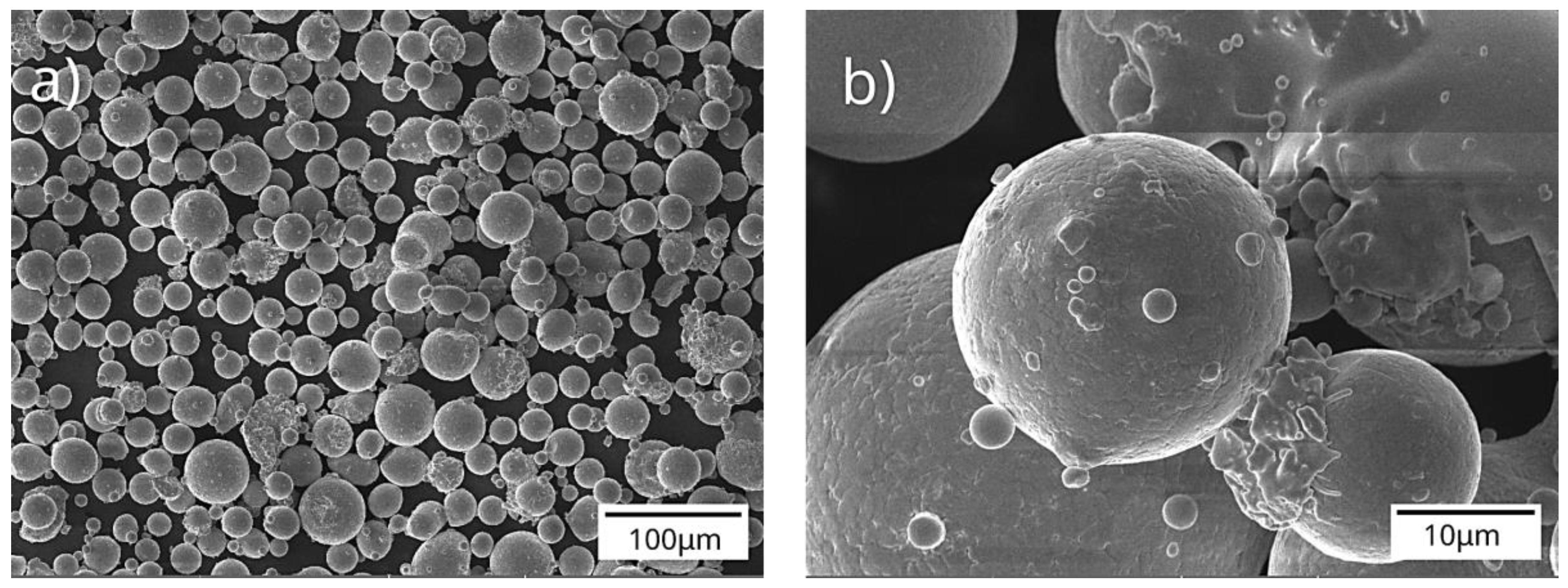
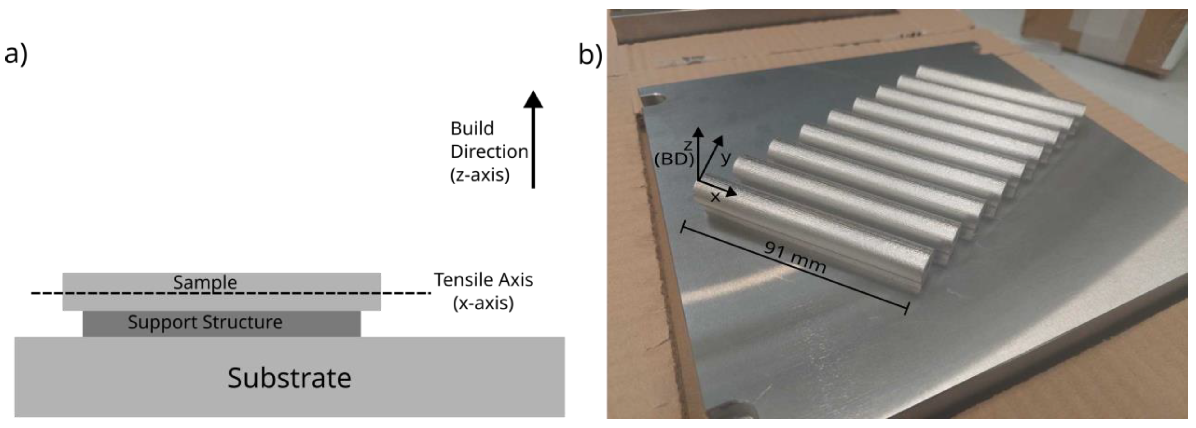
2. Materials and Methods

In this research, Inconel 718 powder provided by F3nice [34] was used for the L-PBF process. The powder was produced from recycled materials, namely leftovers from CNC machining, failed printed parts and disqualified powder, using vacuum induction-melting inert gas atomization (VIGA) technology. The samples are printed with an AMCM M290 (customised EOS M290) machine equipped with 1070 nm wavelength Ytterbium fibre laser. A stripe scanning strategy with laser power of 285 W was used in combination with 960 mm/s scan speed and 0.11 mm hatch distance, leading to a volumetric energy density (VED) of 67 J/mm3. To prevent oxidation during the L-PBF process, the samples were printed in an inert argon gas environment. The process parameters are summarised in Table 1. The recycled powder feedstock is in accordance to ASTM F3055 [35] and has a size distribution of 55.5 μm, 36 μm, and 23.2 μm corresponding to D90, D50 and D10 particle size distribution, respectively. The SEM micrographs showing the particle morphology is given in Figure 1.
To evaluate the worst-case scenario, the samples were printed in the horizontal direction (as shown in Figure 2). This is because the degree of hydrogen embrittlement (HE) is found to be higher in materials with higher yield strength [36]. In L-PBF, horizontally built samples are found to be more susceptible to (HE) than vertically built samples [33]. The AM samples studied herein are investigated in both as-processed and heat-treated conditions. In the remainder of the article, these samples are referred to as AM-AP and AM-HT, respectively. The heat treatment applied in this study involves solutionising at 980 °C for 1 h, followed by double ageing at 720 °C for 6 h in a furnace, then cooled to 620 °C and held for 10 h, which is summarised in Table 2.
The L-PBF Inconel 718 was compared with conventional hot-rolled samples. The conventional hot-rolled samples after heat treatment (Table 2) were supplied by VDM metals GmbH [38]. It represents commercially used Inconel 718 in the industries as per the ASTM B 637 standard [39].
For microstructural characterisation, the samples were polished to mirror finish and etched using Kallings reagent (5 g CuCl2, 100 mL HCl and 100 mL ethanol). The microstructure was then analysed using an Olympus optical microscope. To determine the morphology of the precipitates, a Jeol JSM IT-100 scanning electron microscope (SEM) equipped with energy-dispersive spectroscopy (EDS) was used.
For the AM samples, porosity measurements were additionally taken on the polished surface using a Keyence VHX-5000 digital microscope. A rectangular region of 2 × 2 mm2 was defined and the porosity within this region was determined. The resolution of the pore size is limited to 1 μm. This was repeated in three different regions and the average porosity is calculated.
Vicker’s hardness tests were performed on the samples as a preliminary estimate of mechanical properties. The hardness tests were performed on a Struers Durascan hardness tester with HV5 (5 kgf) scale to obtain the average hardness of the material. Five measurements were taken close to the centre of the sample in the direction perpendicular to the tensile axis (XY-plane in Figure 2), which is the build direction in the case of the AM samples.
X-ray diffraction analysis (XRD) was carried out to qualitatively determine the different phases precipitated in the conventional, AM and AM-HT samples. The XRD measurements were performed in a Bruker D8 Advance diffractometer with Co kα radiation. A step size of 0.035° 2θ with 45 kV and 40 mA was used. The peak identification was carried out in Bruker software Diffrac.EVA.
To characterise the effect of gaseous hydrogen on Inconel 718, the sample design developed by Boot et al. [40] (shown in Figure 3) for slow strain rate tensile (SSRT) test was used. This design has the advantage that the sample acts as the gas containment volume throughout the experiment, thus avoiding the need for autoclaves and sophisticated equipment. The AM-AP, AM-HT and conventional cylindrical samples were machined to the required dimensions for mechanical testing. A standard hydraulic 4-column load frame (MTS 311.21 Servo Hydraulic Load Frame) with a load capacity of 350 kN and modified adapters, as shown in Figure 3, was used to perform the in-situ experiments. The supply of gas during testing was provided through the top adapters connected to gas cylinders of hydrogen and nitrogen, each with a purity of 99%. The SSRT tests were performed with a cross head speed of 1.5 mm/h, which corresponded to a strain rate of ~10−5 s−1. An Instron extensometer (model no: 2620-603) with 10 mm gauge length was then placed on the specimen over the notch. When a specimen began to yield during testing, the extensometer was removed to avoid damage during failure and then the crosshead displacement was used to determine the final strain in the material.
The SSRT tests were performed in both nitrogen (N2) and hydrogen (H2) environments, with a pressure of 150 bar at 25 °C. Two repetitions were performed for each testing condition for repeatability. For the hydrogen tests, the samples were additionally charged for 48 h before the test to allow for hydrogen diffusion within the sample.
After the SSRT tests, the area of cross section after failure (Af) is determined at the fracture location using Keyence VHX-5000 digital microscope. The percentage reduction in area (RA) is found by comparing it with the initial cross sectional area (A0) [40]:
%RA = (A0 − Af)/A0 × 100%
The degree of hydrogen embrittlement is measured as the relative reduction of area of samples tested in nitrogen (%RAN2) and hydrogen (RAH2) environment [40]:
HEI = (%RAN2 − %RAH2)/%RAN2 × 100%
where HEI is the hydrogen embrittlement index, representing the percentage of ductility that was lost due to the presence of hydrogen.

3. Results and Discussion

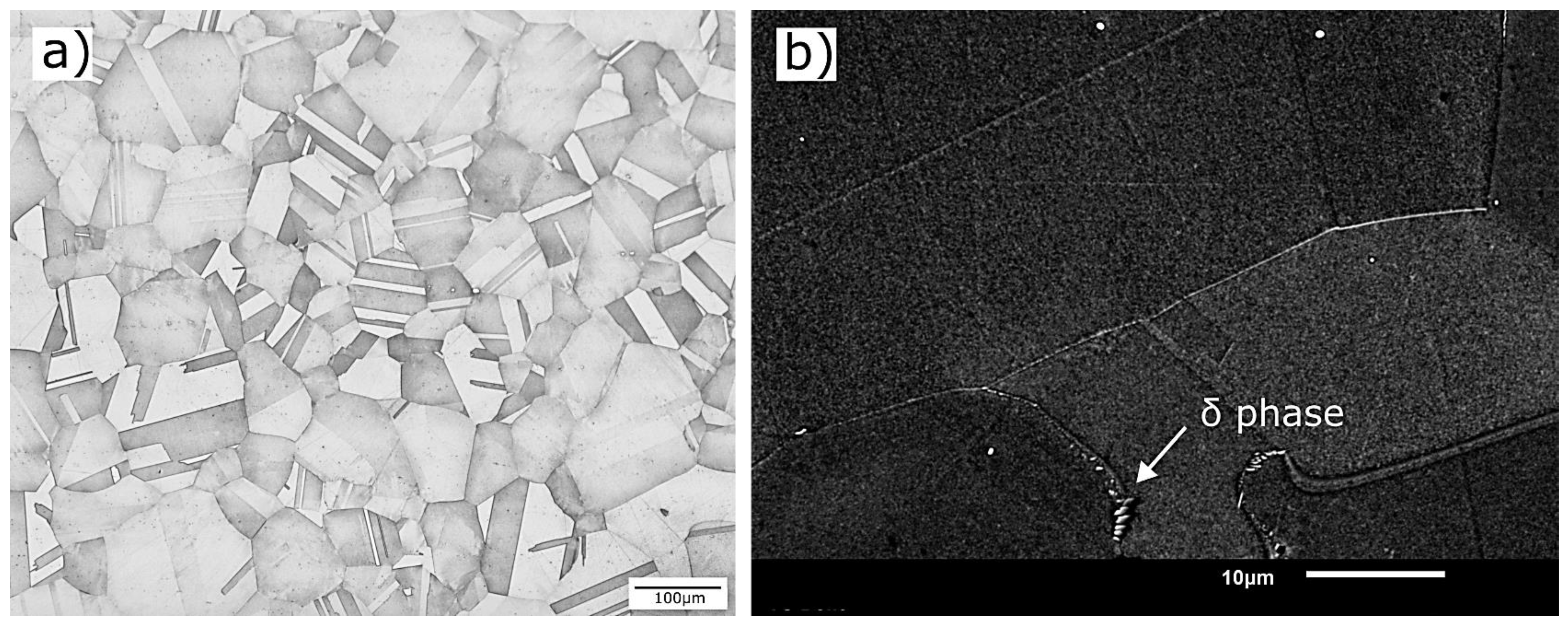
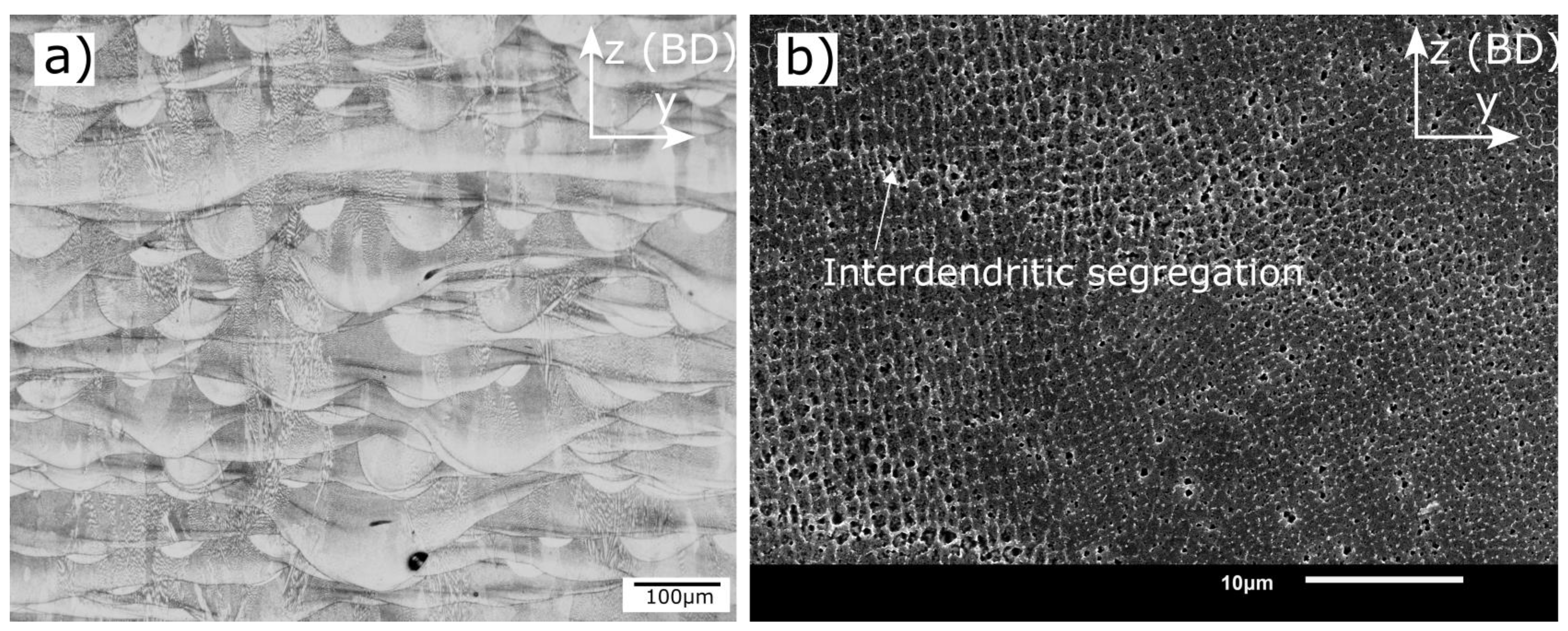
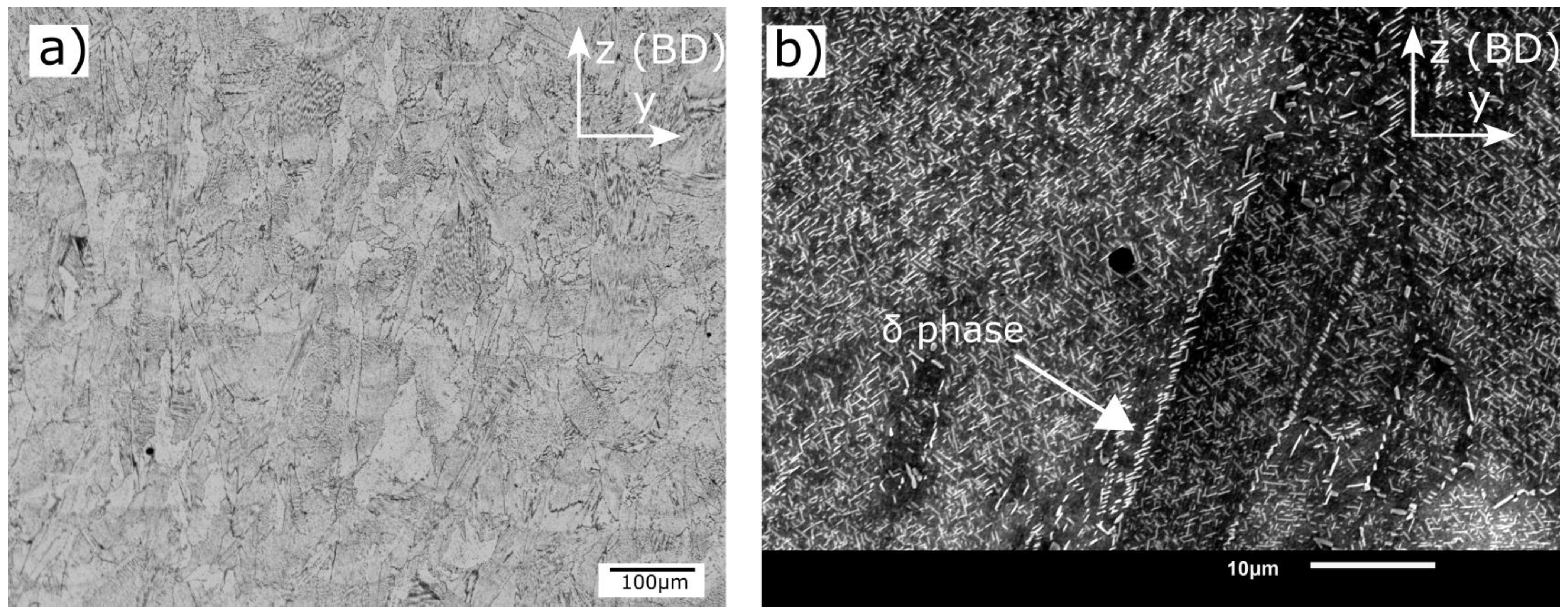
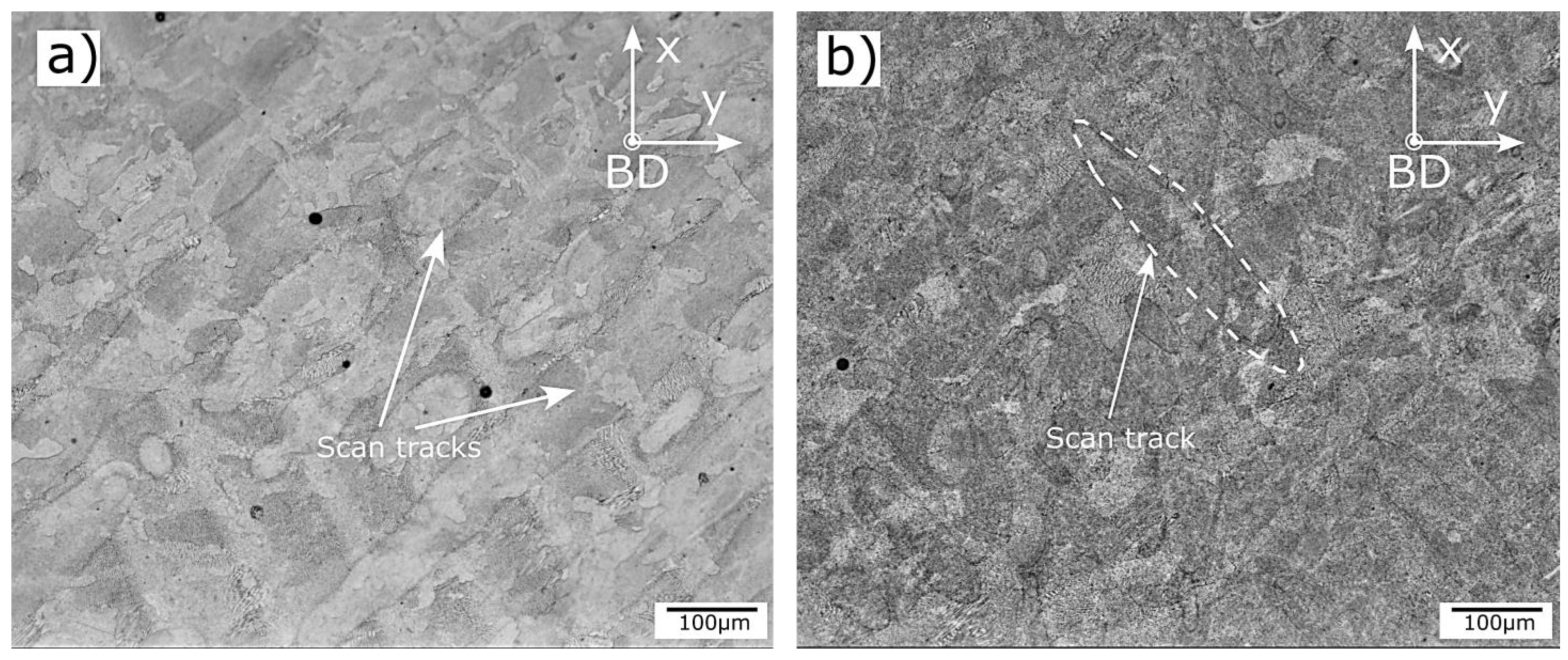
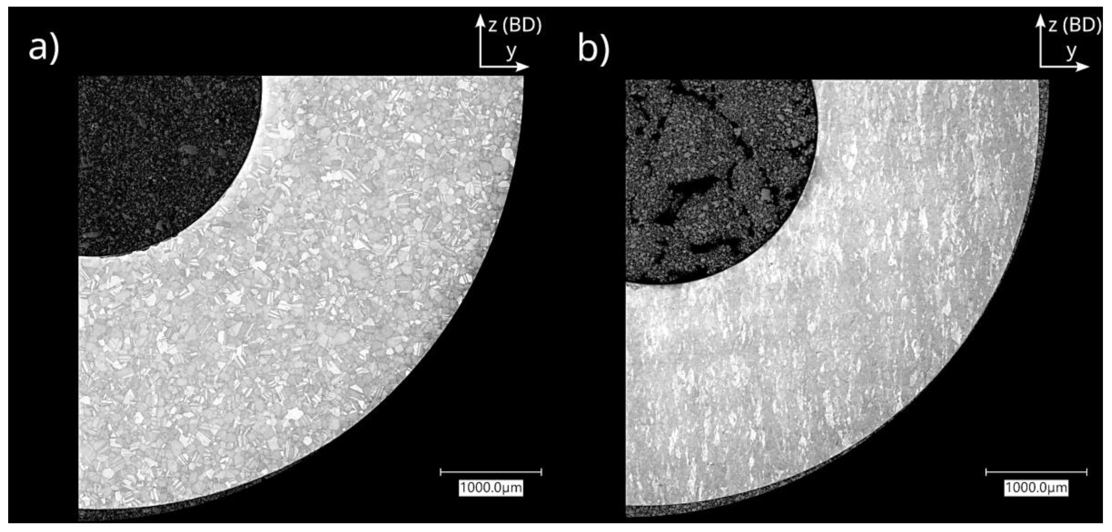
3.1. Microstructural Characterisation

The composition of the conventional and AM samples, as measured by X-ray fluorescence spectroscopy, is given in Table 3. A slight variation in the composition of the major alloying elements is noted, but is within the allowed limits as per ASTM B637 standard [39]. The elements Co and Cu are not detected in the AM samples; these elements are added to impart solid solution strengthening in Ni-based superalloys, and are not expected to majorly influence the precipitation of phases in this study [41].
Figure 4 shows the microstructure of the conventional Inconel 718 sample after heat treatment with equiaxed grains and annealing twins. During the heat treatment, the solutionising temperature of 1032 °C is higher than the δ solvus temperature (~1000 °C) [12], resulting in the dissolution of the δ phase. Cai et al. [42] reported that after 1 h of holding time at 1020 °C the δ phase fully dissolves in the matrix. In the current study at high magnification (Figure 4b), precipitates of δ phase with a size of ~0.8 μm are seen along the grain boundaries. Nevertheless, the fraction of the δ phase observed is small, as it is found only in certain regions and not throughout the grain boundaries. The γ′ and γ″ strengthening phases form during the subsequent ageing heat treatment at 790 °C for 6 h. As these strengthening phases precipitate in the nanometre range, they are hard to discern in a scanning electron microscope.
Along the building direction, the AM-AP sample shows fish-scale-like morphology (Figure 5a), arising from the remelting of previous layers during layer-wise deposition of material. Due to the presence of solidified layers, grain growth in L-PBF occurs epitaxially; this is seen as dendritic structures spanning multiple melt pools in the microstructure [20]. Figure 5b) shows the cellular structures of the columnar dendrites. Laves phase (marked by arrows) forms in the interdendritic regions due to the micro-segregation of Nb and Ti during solidification [43]. As these segregations are detrimental to mechanical properties, post-processing heat treatments are recommended [20].
For AM-HT samples, solutionising the temperature (980 °C) and time (1 h) during the SA heat treatment is insufficient for complete recrystallisation. This is evident from the microstructure shown in Figure 6, where partial melt pool boundaries are still visible. In addition, at 980 °C only partial dissolution of Laves phase occurs and diffusion of Nb is inadequate for homogenisation. The partial dissolution of Laves phase leads to an increase in the concentration of Nb in the neighbourhood. This results in the formation of the acicular delta phase with a size of ~1.1 μm along the grain boundaries, as seen in (Figure 6b). This is in agreement with the observations of Chlebus et al. [44], Li et al. [43] and Zhang et al. [45]. A two-step ageing heat treatment is also performed for the precipitation and coarsening of γ′ and γ″ strengthening phases. It is found that SA heat treatment does not eliminate the anisotropy in microstructure entirely, as complete recrystallisation does not occur. Sabelkin et al. [46] recommends a non-traditional heat treatment, which involves annealing at 1160 °C for 4 h to allow complete recrystallisation and anisotropy elimination.
The microstructures of AM-AP and AM-HT, perpendicular to the build direction (xy-plane), are shown in Figure 7. Scan tracks representative of the scanning strategy are visible in the AM-AP samples. Wang et al. [47] performed EBSD analysis and reported that the grains appeared equiaxed in this plane. Popovich et al. [19,48] performed similar studies for functionally graded Inconel 718 and reported that laser power strongly influenced texture, in turn, affecting anisotropy in samples. It was also found that HIP treatment promoted recrystallisation, whereas annealing heat treatment at 850 °C did not. This supports the observation in Figure 7b) vaguely showing melt pools (marked by dotted line) after only heat treatment.

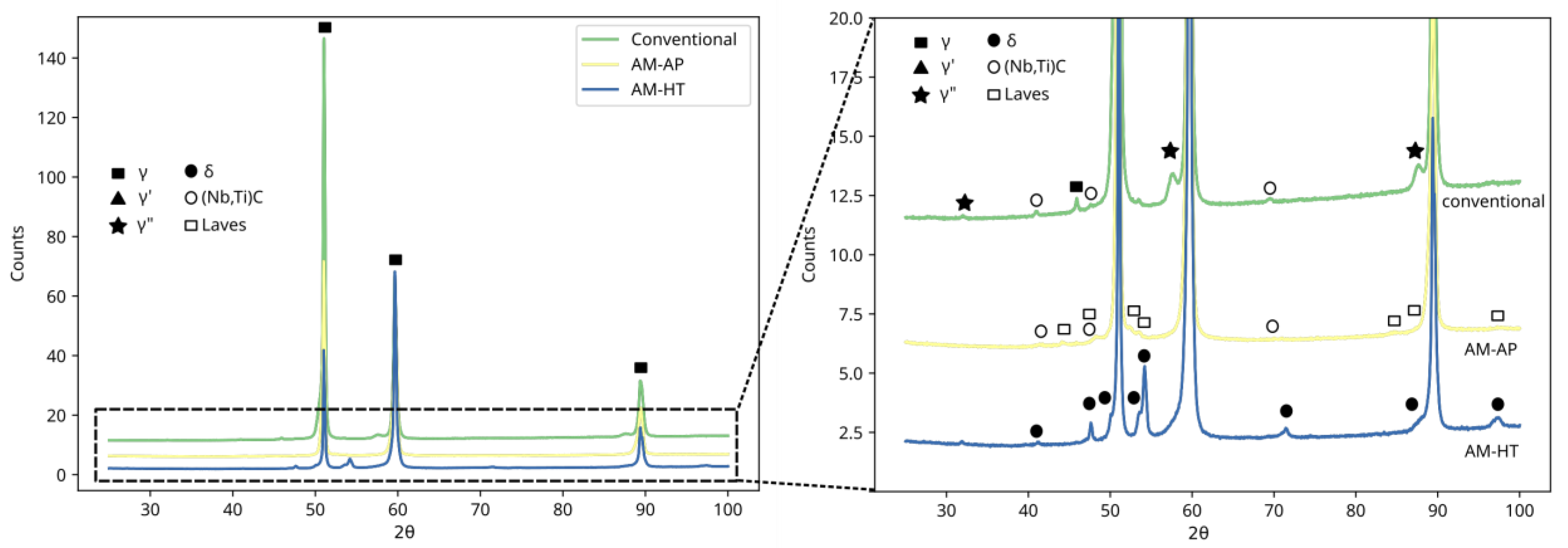
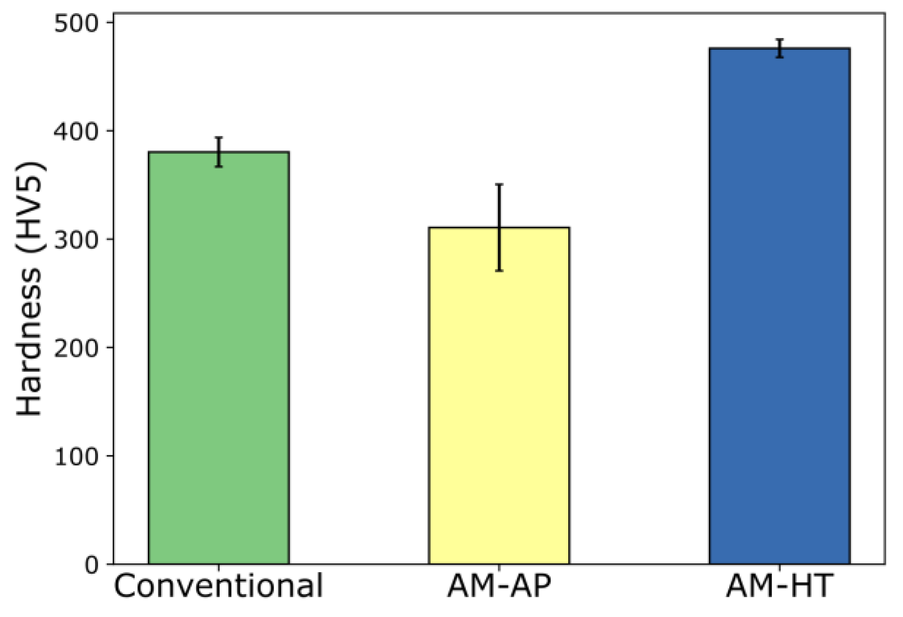
3.2. XRD Analysis and Vickers Hardness Measurements

XRD analysis was performed to confirm the presence of different phases. Figure 8 shows the XRD measurement results for conventional, AM, and AM-HT. For all samples, the primary matrix phase (γ) shows the strongest peaks. Only qualitative phase analysis is performed, as most of the phases give peaks which overlap with the primary matrix, thus making it hard to distinguish them. In the conventional samples, small peaks identified as γ″ are seen close to the γ matrix peaks. Additionally, peaks corresponding to Ti, Nb—carbides are also visible. Even though the microstructure shows the presence of the δ phase, corresponding peaks were not identified in the XRD measurement; this is due to the poor resolution of XRD when the phase fractions are less than 5%.
For the AM samples in the as-processed condition in addition to the matrix phase, small peaks corresponding to Ti, Nb—carbides and Laves phase are seen. As explained in the previous section, the micro-segregation of Nb and Ti at the interdendritic regions is the reason for the precipitation of these phases.
In the heat-treated samples, the peaks for Laves phase are no longer visible; as during the heat treatment, Laves phase partially dissolves, thus reducing the fraction of phase present. In addition, the dissolution leads to an increase in Nb concentration in the neighbourhood, and the temperature is insufficient for the homogenisation of the elements in the matrix. This leads to the formation of the δ phase in these regions during heat treatment [45]. Small peaks corresponding to the δ phase are visible for the AM-HT sample in Figure 8, confirming the same.
The peaks of γ′ and γ″ are difficult to separate from the primary γ matrix, as they are coherent precipitates [12]. However, as the fraction of the precipitates increases, the strength of the material also increases. Thus, hardness measurements can serve as a first estimate for the precipitation of the strengthening phases.
The Vickers hardness measurements of the samples are given in Figure 9. The conventional sample shows a hardness of 380 ± 13 HV5, which is in the expected range for the heat-treated wrought alloys [49]. In the case of AM samples, after heat treatment, the sample shows a hardness of 476 ± 8 HV5, which is 53% higher than the hardness of the AM-AP sample (310 ± 39 HV5). This is expected, as the heat treatment introduces γ′ and γ″ strengthening phases, which are absent in the as-processed condition [44]. On the other hand, even after the precipitation of γ′ and γ″ phases, the conventional sample shows a hardness value lower than AM-HT samples. The difference in the hardness of AM-HT and conventional samples can be attributed to the fine microstructure induced by the L-PBF process. This is evident when comparing Figure 4 and Figure 6, and is in agreement with data reported by Tanja et al. [50]: where the grain size of L-PBF Inconel 718 is reported to be finer than the forged counterpart by a factor of 10. The higher hardness values of AM-HT would correlate to a higher yield and tensile strength [51]. Thus, when considering hydrogen embrittlement, AM-HT is expected to have a higher degree of HE compared to AM-AP and conventional samples.
Hardness measurements are not influenced by the presence of porosity in the L-PBF samples [52]. However, depending on the shape and size of the pores, they can be detrimental to mechanical properties.
Porosity is a defect commonly observed in the components produced from the L-PBF process and is absent in the wrought counterpart, as observed in Figure 10. The AM-AP and AM-HT samples show comparable porosity values of 0.09 ± 0.02% and 0.05 ± 0.01%, respectively, making it nearly defect-free (99.9% density) material. Spherical pores signifying gas entrapment were the most commonly seen pore morphology, with the largest pore size being 45 μm. The spherical pores form during the L-PBF process, when the inert gas used to prevent oxidation of powder or the gas already entrapped in the powder feedstock gets trapped in the melt pool during solidification [20]. A few lack of fusion defects (LOF) were also seen; as the name suggests, these defects arise due to insufficient bonding between two layers or scan tracks. Due to their shape, they are detrimental to the mechanical properties as crack initiation can occur at these locations.

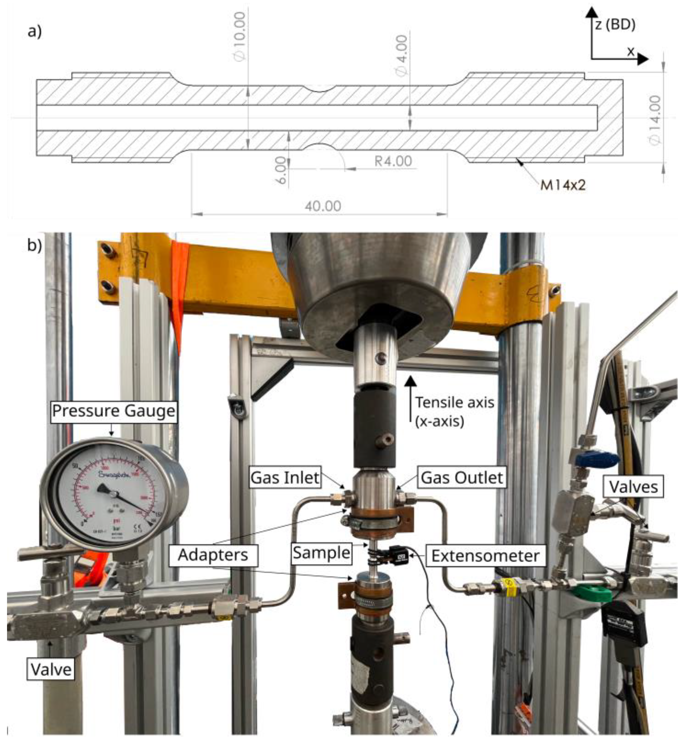
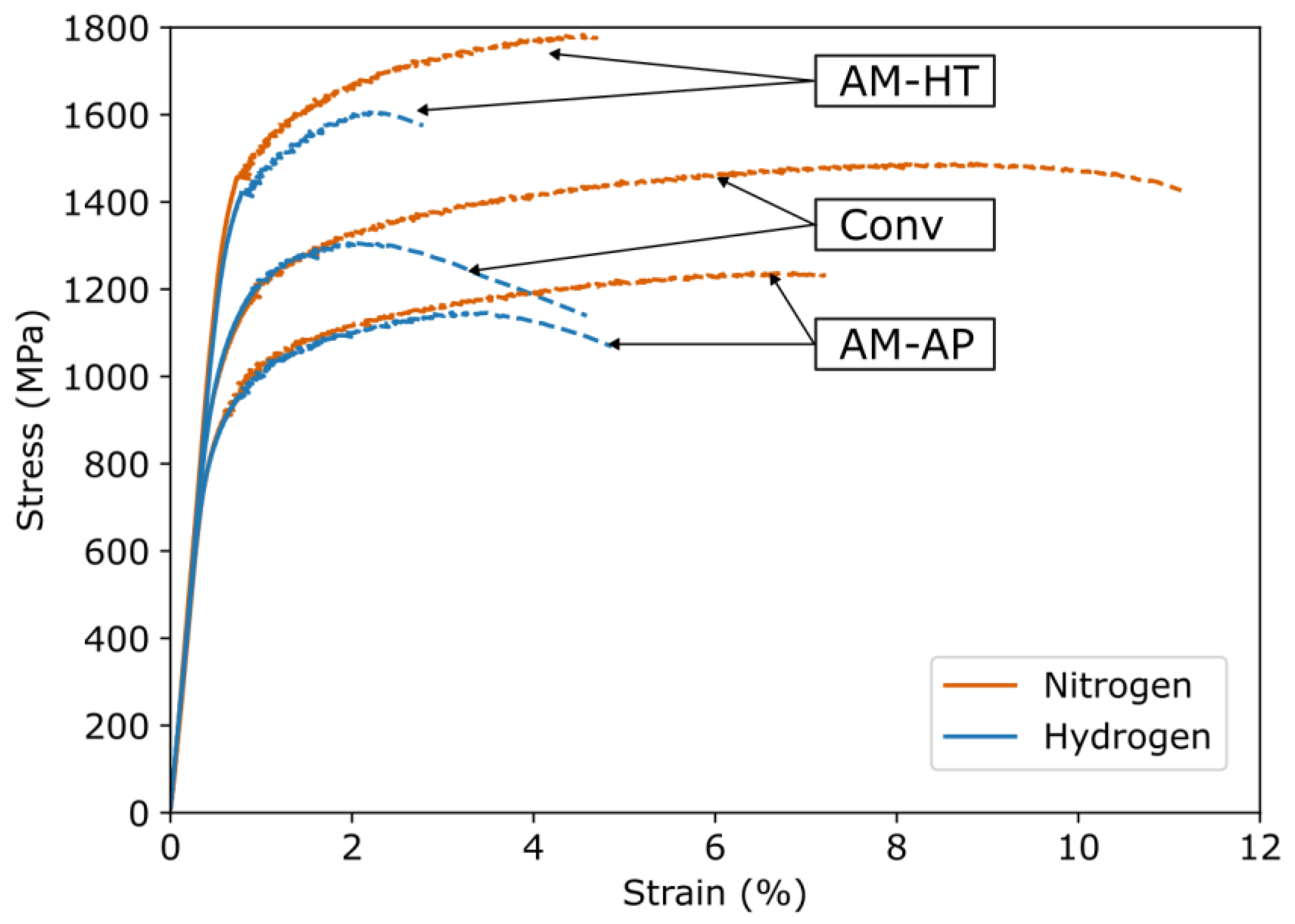
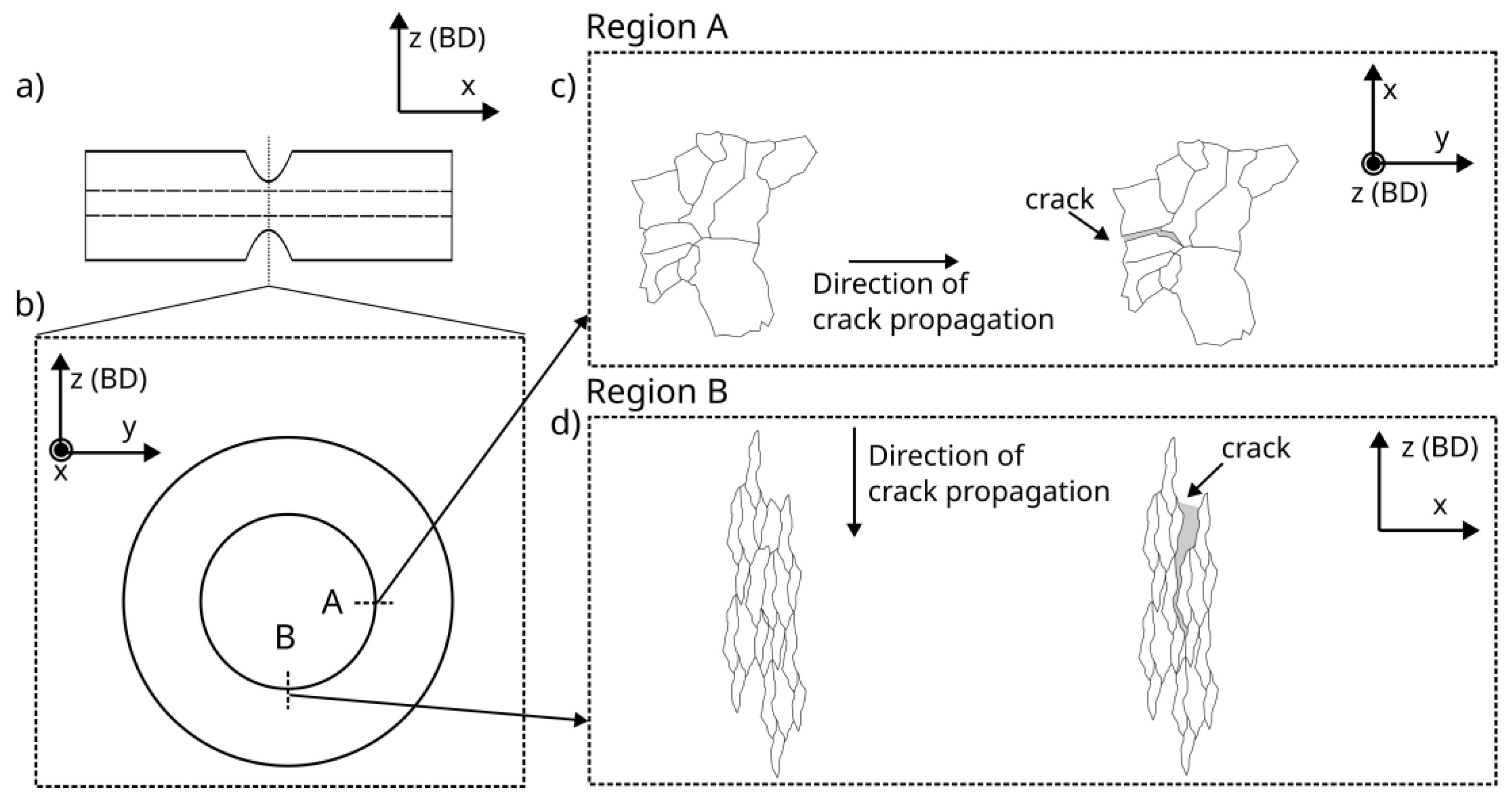
3.3. In-Situ Gaseous Hydrogen Slow Strain Rate Testing (SSRT)
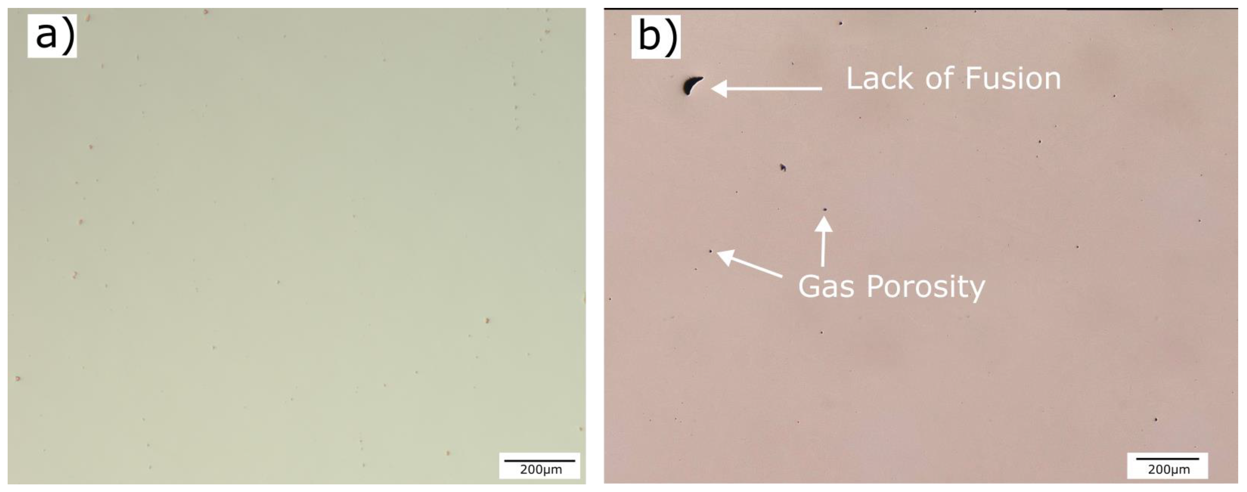
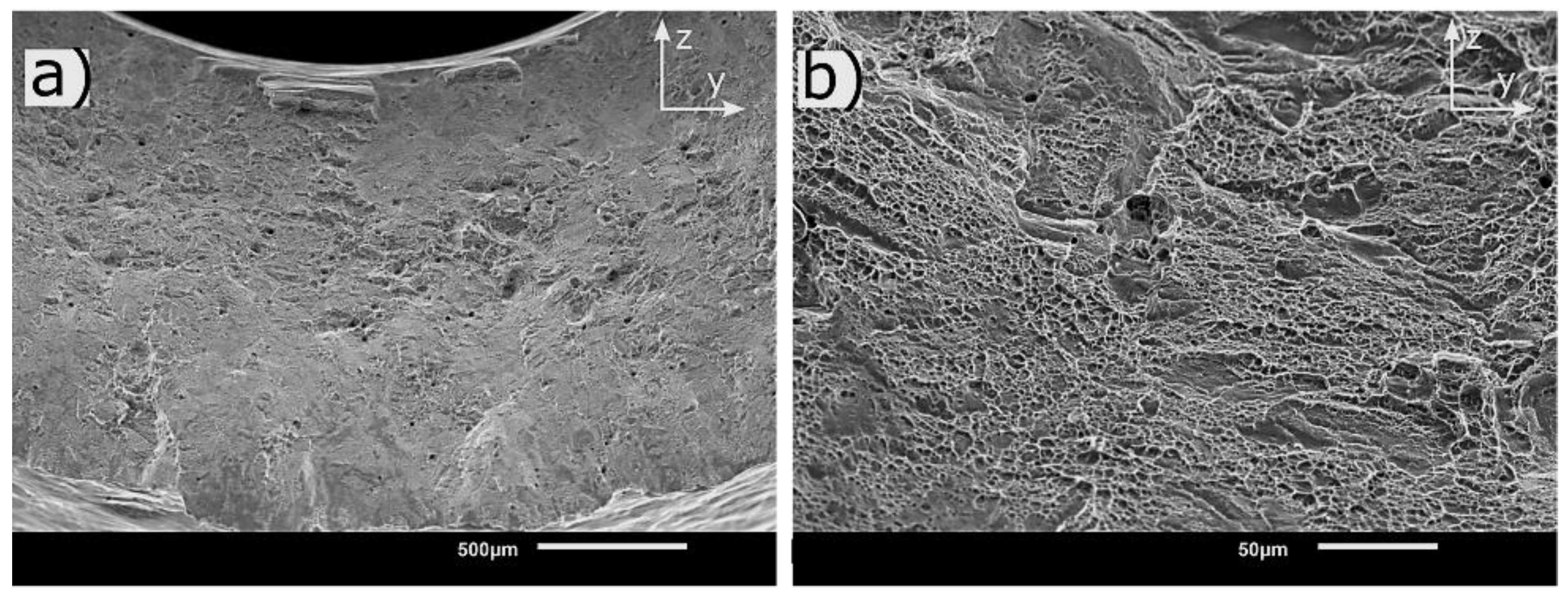
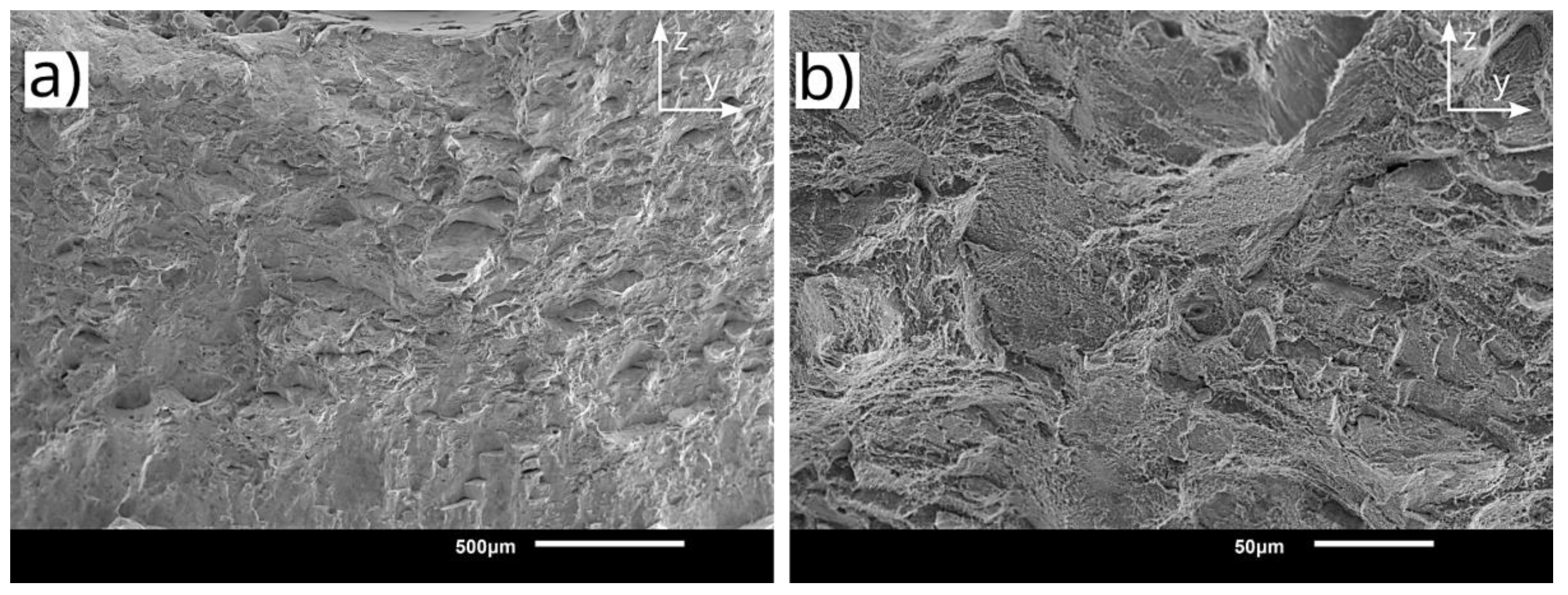
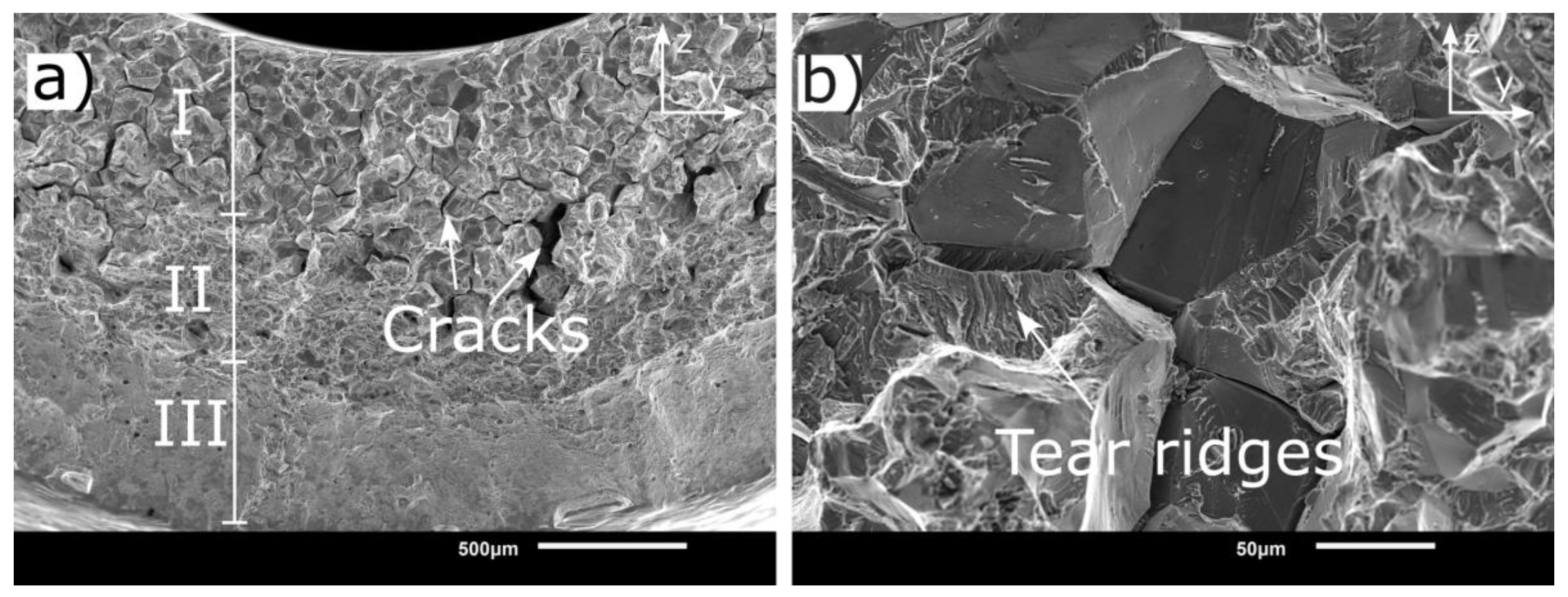
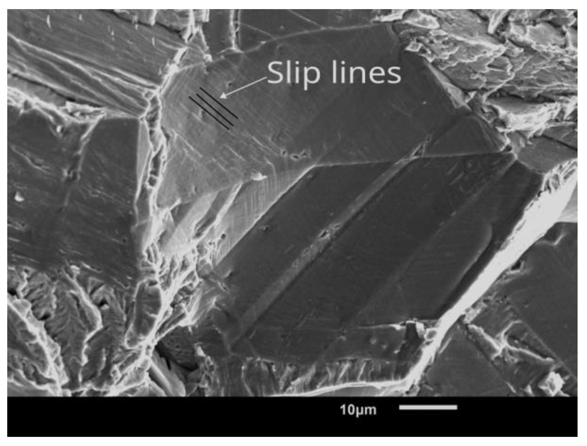
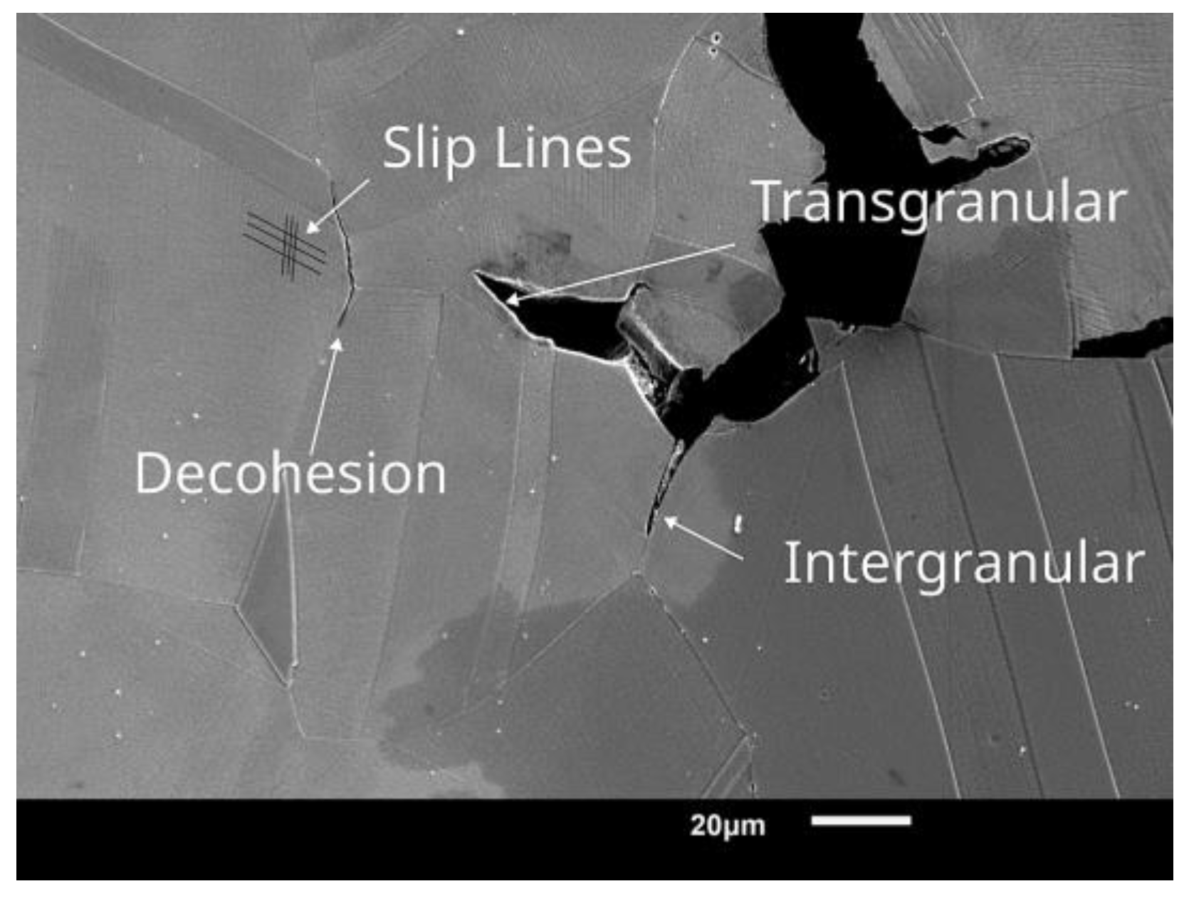
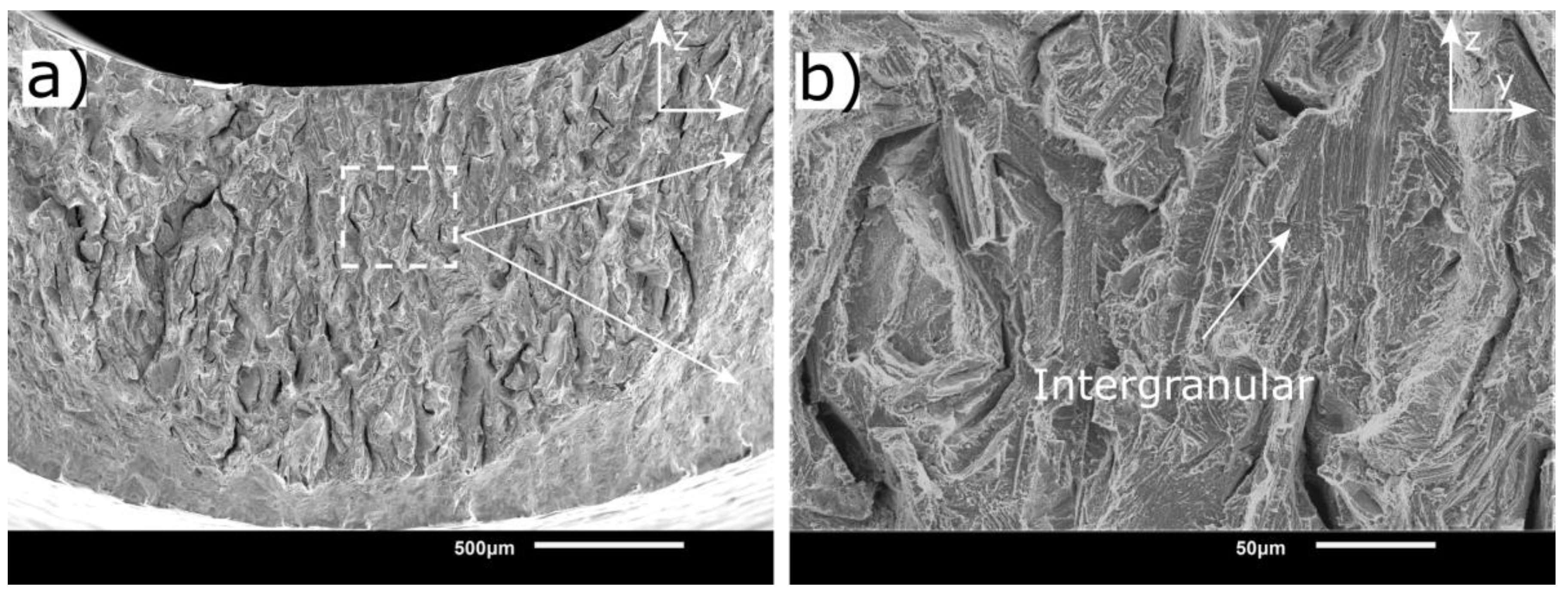
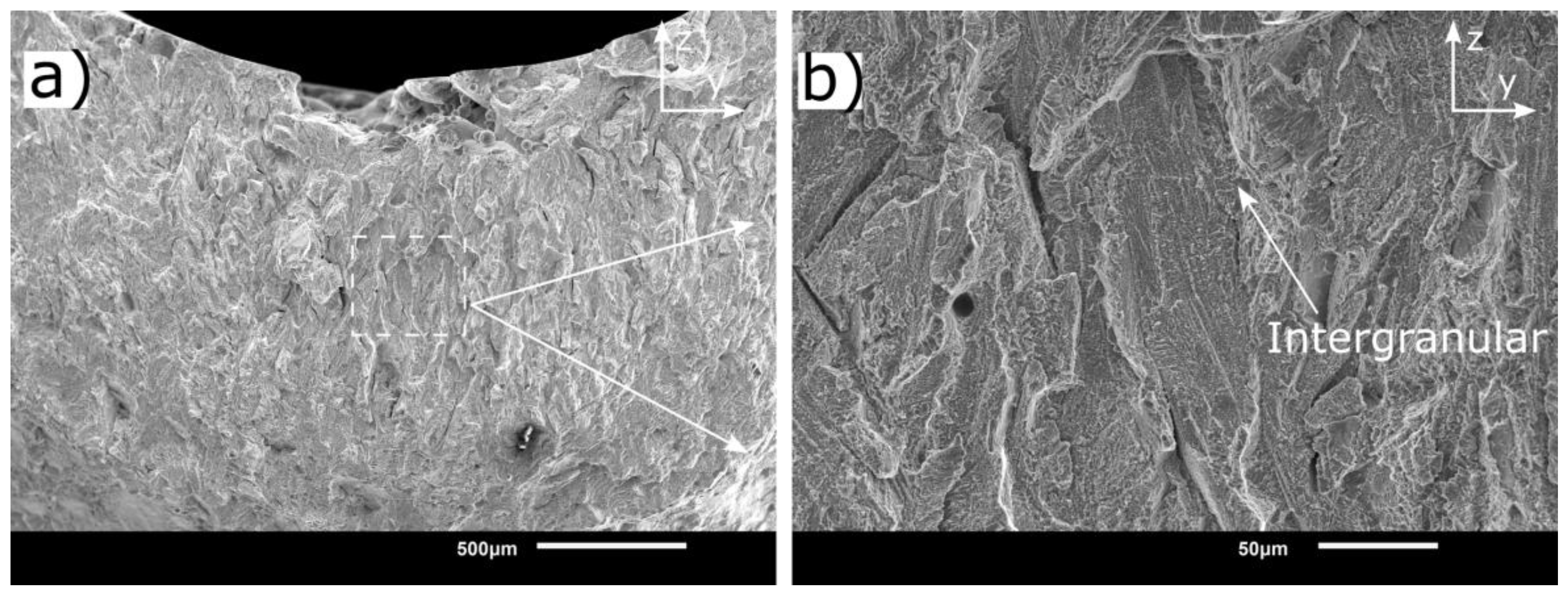
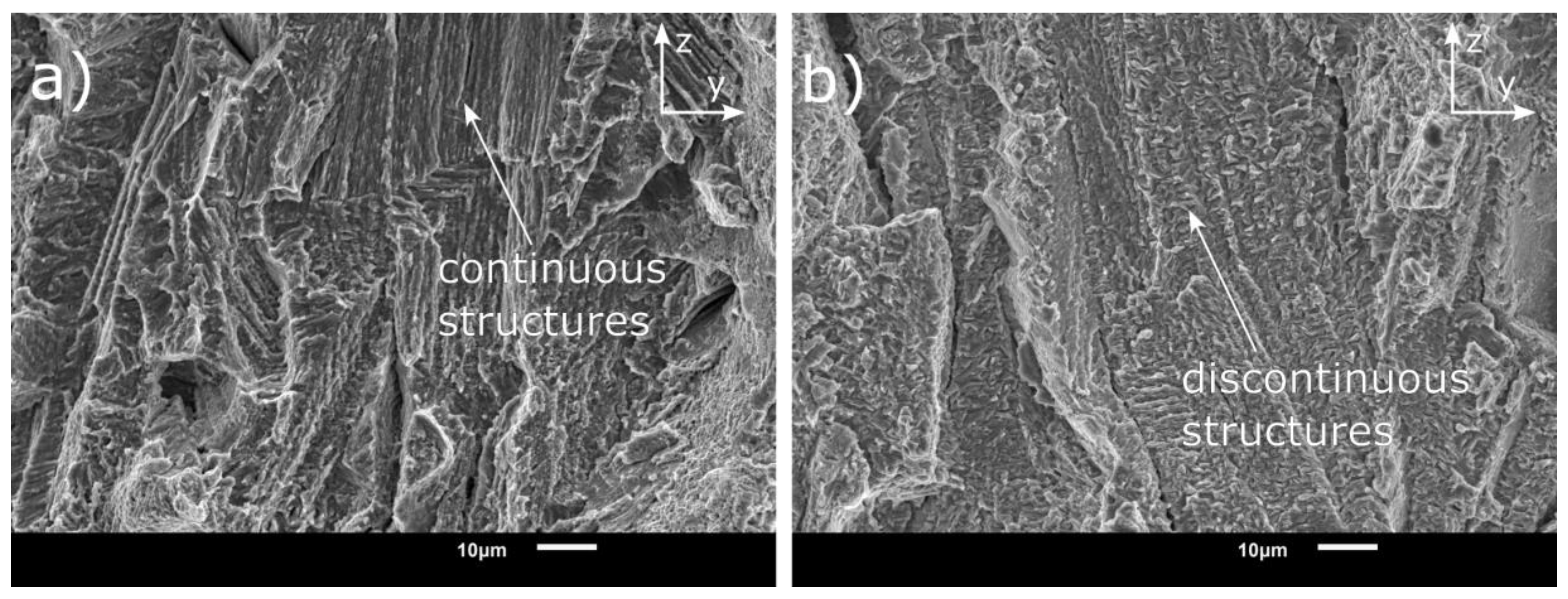
The results of the SSRT test are summarised in Table 4 and representative plots for each testing condition are given in Figure 11. As can be seen, the major difference occurs with the AM heat-treated samples where the double ageing with longer duration is employed. With the precipitation of strengthening phases, an increase of 62% in the yield strength (Y.S.) and a 57% increase in the ultimate tensile strength (UTS) was seen for the AM-HT sample. As accurate quantification of the strengthening phases is not performed in this study, information from the literature is used as reference.
Embrittlement is observed in both conventional and AM samples when hydrogen was introduced. However, the degree of hydrogen embrittlement varies. A general observation for hydrogen samples which was not found in the literature was the drop in load after reaching particular stress. In a uniaxial tensile test, a load drop before failure signifies a reduction in load-bearing cross-sectional area or softening. As no significant load drop in the nitrogen test condition is observed it is unlikely that softening occurs. This can be further confirmed by looking at the fracture surface as occurs in a later section.
Hydrogen embrittlement index can serve as a quantitative comparison between conventional and AM samples. The hydrogen embrittlement index (HEI) of the samples are provided in Figure 12 with higher values signifying a higher degree of embrittlement. The AM samples show lower degree of embrittlement than the conventional samples. In the case of AM-AP samples, the difference could arise due to the absence of strengthening phases γ′ and γ″. Rezende et al. [53] studied the influence of γ″ precipitates on the HE behaviour and reported that its presence aggravated hydrogen embrittlement. Similar observations were also seen by Hesketh et al. [33], where the lower degree of HE was attributed to the lower tensile strength of AM-AP samples. In general metals having high tensile strength show a higher degree of hydrogen embrittlement [36]. Surprisingly in this study, the AM-HT samples, which demonstrate the highest yield strength, show the least embrittlement compared to AM-AP and conventional samples, thus deviating from the earlier mentioned trend. This behaviour could arise due to the unique anisotropic microstructure inherent to the L-PBF process, which could affect how hydrogen interacts with the material. To better understand this, the fracture surface is looked into to help identify the HE mechanisms.

3.4. Fractography

The fracture surfaces of the conventional and AM samples tested in ambient conditions are given in Figure 13 and Figure 14 respectively. Conventional samples tested in a nitrogen environment (Figure 13a) show features of a typical ductile failure, i.e., failure by micro-void coalescence (Figure 13b). The void size was determined to be ~4.5 μm.
In the case of AM samples, both AM-AP and AM-HT show a ductile mode of failure in a nitrogen environment; however, the micro-voids appear to be ~65% smaller than the conventional samples. The smaller dimple size (~1.5 μm) is attributed to the fine microstructure produced from the L-PBF process [45,54]. As no significant variation is noted in the fracture surface of AM-AP and AM-HT samples, only one representative surface is shown here (Figure 14).
The conventional samples after hydrogen gaseous charging show severe embrittlement on the fracture surface, as seen in Figure 15. Additionally, it is noted that fracture initiates from the inner surface of the sample. Three distinct regions can be observed on the surface (Figure 15): (1) brittle intergranular region, (2) quasi-cleavage region and (3) ductile region. Severe cracking (marked by arrows) on the fracture surface is also seen.
The brittle region in the in-situ sample consisted of features representative of the grain structure. Tear ridges signifying plasticity are also visible in this region. Several researchers have reported fracture surfaces similar to this after electrochemical charging [14,55]. Zhang et al. [55] reported that though the features show an intergranular mode of failure, the crack initiates and propagates through dislocation slip bands and hence is actually transgranular in nature. In this case, the proposition by Zhang et al. [55] that failure initiates at the slip bands requires further analysis, as it is unlikely that hydrogen has sufficient time for diffusing within the grain.
To identify the dominant mechanism, the intergranular region on the fracture surface is analysed. On a macro scale, the brittle features point towards hydrogen-enhanced decohesion (HEDE) mechanism [17]. However, on taking a closer look at the facets, dislocation slip lines signifying plastic deformation are visible (Figure 16). This indicates a possibility for hydrogen-enhanced localised plasticity (HELP) or adsorption-induced dislocation emission (AIDE) mechanism [17]. AIDE is considered here as the hydrogen is present on the surfaces of the crack, which can be adsorbed leading to dislocation emission from the crack tip.
Another observation that needs to be accounted for is the load drop in the SSRT curves (Figure 11). It was found that the drop in load occurred only after a particular stress level is reached. As explained earlier this means a reduction in load-bearing area; here, it signifies the beginning of decohesion. The strain at this point was determined to be 2%. As Inconel 718 has a low stacking fault energy, it is found to show planar deformation [56]. The slip lines visible on the facets could be a consequence of this 2% strain. Further, it could also be possible that the decohesion occurred where the slip lines intersected with the grain boundaries. A cross-section of the fracture surface was analysed to understand it better.
Figure 17 shows the cross-section of fracture at the brittle region; both intergranular and transgranular modes of failure are observed. A large number of dislocation slip lines are also visible; the transgranular failure could have occurred along these slip lines. The tear ridges seen in Figure 15 confirm this. A closer look with a higher resolution electron microscope could help better understand why there was a transition from intergranular to transgranular mode of failure. Decohesion along grain boundaries ahead of the crack is also seen. It is unlikely that hydrogen diffuses far ahead for the decohesion to occur during the test. This decohesion could be a consequence of another crack front in the plane. It is likely that the mode of failure is an interplay between HEDE, HELP and AIDE mechanisms.
Similar to the conventional samples, the hydrogen AM samples also show a severely embrittled region (Figure 18 and Figure 19). A distinct difference observed here is that the HE region is directional for all AM samples (both AM-AP and AM-HT), unlike the conventional samples, which show homogeneous embrittlement throughout the fracture plane. A representative macroscopic fracture surface from an AM sample and conventional sample is given in Figure 20. The observed difference could arise due to the microstructural anisotropy in the L-PBF samples. Features representative of elongated grains are visible in the HE region for both AM-AP and AM-HT samples. Further, these HE regions appear to be oriented along the build direction, as can be deduced from these elongated features. The lower degree of HE in AM samples compared to the conventional samples could be a consequence of this preferential anisotropy; as only a small region is embrittled and the remainder of the sample retains its ductility. To better understand this, the microstructure in the fracture plane was analysed.
In the conventional sample, in all planes (xy, xz and yz-planes) a uniform equiaxed microstructure is observed. Microstructure along the fracture plane (yz-plane) is shown in Figure 21a). This means that after crack initiation, its propagation occurs the same way in all the directions of the fracture plane (yz-plane). Even if multiple cracks initiate at the inner surface as seen in the case of conventional samples, the energy required for crack propagation remains the same.
As seen earlier, it is clear that the AM samples show different microstructures along different planes, with both AM-AP and AM-HT showing similar features. The microstructure along the fracture plane (yz-plane), as seen in Figure 21b), shows elongated grains oriented along the L-PBF build direction. A similar microstructure is also seen in the xz-plane; however, in the xy-plane the microstructure is different. As explained in microstructure section, it is because xy-plane is the laser scanning plane. A schematic representation of this difference in the fracture plane is given in Figure 22.
Crack propagation occurs in material when there is sufficient energy for creating two new surfaces [57]; as it is a brittle mode of failure energy for plastic deformation is not considered here. In a uniaxial tensile test, this energy is provided by the tensile load. If Es is the energy required to create two new surfaces, and assuming that the elongated grains are of the similar grain boundary area. The energy required for the crack to travel across a grain boundary surface would be the same in both region A and B (Figure 22). This is because the area of the two new surfaces created by the crack would be the same. However, the distance the crack travels by expending this energy is much larger in the z-direction (build direction) than in the y-direction; because the longer axis of elongated grains is oriented in the crack propagation direction as shown in Figure 22c. This is confirmed from the fracture surfaces, where along the y-direction the embrittled region is found to be ≈175 μm wide, while along the z-direction the embrittled region is an order of magnitude higher (≈1.5 mm). A more in-depth analysis is required to understand why there is an order of magnitude difference in the embrittled region.
Anisotropy in the vertically (tensile axis along the z-axis) and horizontally built samples (tensile axis along the x or y-axis) are commonly reported in the literature [20]. Hesketh et al. [33] studied the effect of orientation on hydrogen embrittlement of L-PBF Inconel 718 by in-situ electrochemical charging, and reported that the horizontal cylindrical samples exhibited higher degree of embrittlement compared to vertically built ones. The differences in the experimental conditions in the two studies makes it difficult to perform a quantitative analysis. Nevertheless, the trend in anisotropy is established. A similar study was done by Li et al. [31], where the HE behaviour of AM-produced Inconel 718 on dog bone specimens with two different horizontal orientations was looked into, keeping the long axis parallel to the tensile axis. It was reported that the sample with a microstructure similar to the Figure 22 c showed a higher degree of HE. This confirms the anisotropy in flat specimens built in two different horizontal directions. In a ductile mode of failure, it is difficult to observe features on the fracture surface which could be a result of this anisotropy within a horizontally built sample. This further shows, the need for careful design considerations when using L-PBF components.
Among the AM-AP and AM-HT samples (Figure 18 and Figure 19, respectively), the former shows prominent brittle features and cracks on the fracture surface. This is in line with the observation of higher HEI for the AM-AP compared to AM-HT in the previous section. At high magnification (Figure 23), continuous dendritic structures are visible in the AM-AP samples inside the grain-like features; whereas, in the AM-HT samples the dendritic structures appear discontinuous. Li et al. [31] reported that in the as-processed state, the hydrogen-assisted cracking originated between γ matrix and Laves phase. Hence, failure may occur more easily along the dendritic structures in the as-processed state, thus leading to a higher degree of embrittlement. This is also supported by the observation of Lin et al. [58], where it was reported that the cellular structures in L-PBF produced 316 L stainless steel enhanced the diffusion of hydrogen and induced defects. This could be the reason for the features to be less prominent in the heat-treated condition as partial dissolution of Laves phase occurs [48], as seen in the microstructure section.
Li et al. [31] and Lee et al. [30] reported that cellular dendritic structures in the AM as-processed state did not influence HE. The contrasting results could be a consequence of testing conditions, sample geometry and orientations. As seen here, the anisotropy led to directional crack growth in hollow cylindrical samples. These features would not be clearly evident in flat dog-bone specimens. Additionally in these studies, SSRT tests were performed after electrochemical pre-charging which means the concentration of hydrogen remained similar in both as-processed and heat-treated conditions. As the yield strength of the as-processed samples are low, for the same hydrogen concentration as heat-treated samples, the degree of embrittlement would be low. However, in this study, there is a continuous supply of hydrogen at the crack surfaces leading to a higher degree of embrittlement.
Another aspect that needs to be considered is the experiment duration. As the crosshead speed is kept constant, the duration of experiment for each set of samples is different. This is more pronounced for samples with different yield strengths, as they begin to strain plastically at different times. To understand this better, consider an elongation of 1 mm; the time taken for this elongation is same for all samples, as it is displacement-controlled. However, as elongation is different for each sample, the duration of the experiment is different for each sample set. This would lead to a difference in the hydrogen uptake and diffusion during the experiment (although the same 48 h pre-charge time was applied for all samples). The elongation of the AM-AP samples at failure was found to be ≈5.4%, whereas for AM-HT it was only 2.8%. This means after yielding, HE in AM-AP sample occurs in a longer duration than the AM-HT samples. This could be the major reason why higher degree of embrittlement is observed. Tarzimoghadam [59] had similar observations, where it was reported that the annealed specimens showed a ∼70% drop in elongation even though the intermetallic precipitates were absent and the yield strength was only 400 MPa.
Although porosities were observed on the fracture surface of AM samples, they did not appear to influence HE, which is due to the negligible amount of porosity in L-PBF samples. Hesketh et al. [33] also reported similar findings. In theory, porosity would be detrimental as it would reduce the cross-sectional area and can act as a stress concentrator, aggravating hydrogen embrittlement.

4. Conclusions

This study focused on the in-situ hydrogen gas embrittlement behaviour of 3D printed Inconel 718, produced from recycled powder as compared to the conventional wrought counterpart. Based on the study, the following conclusions can be made:
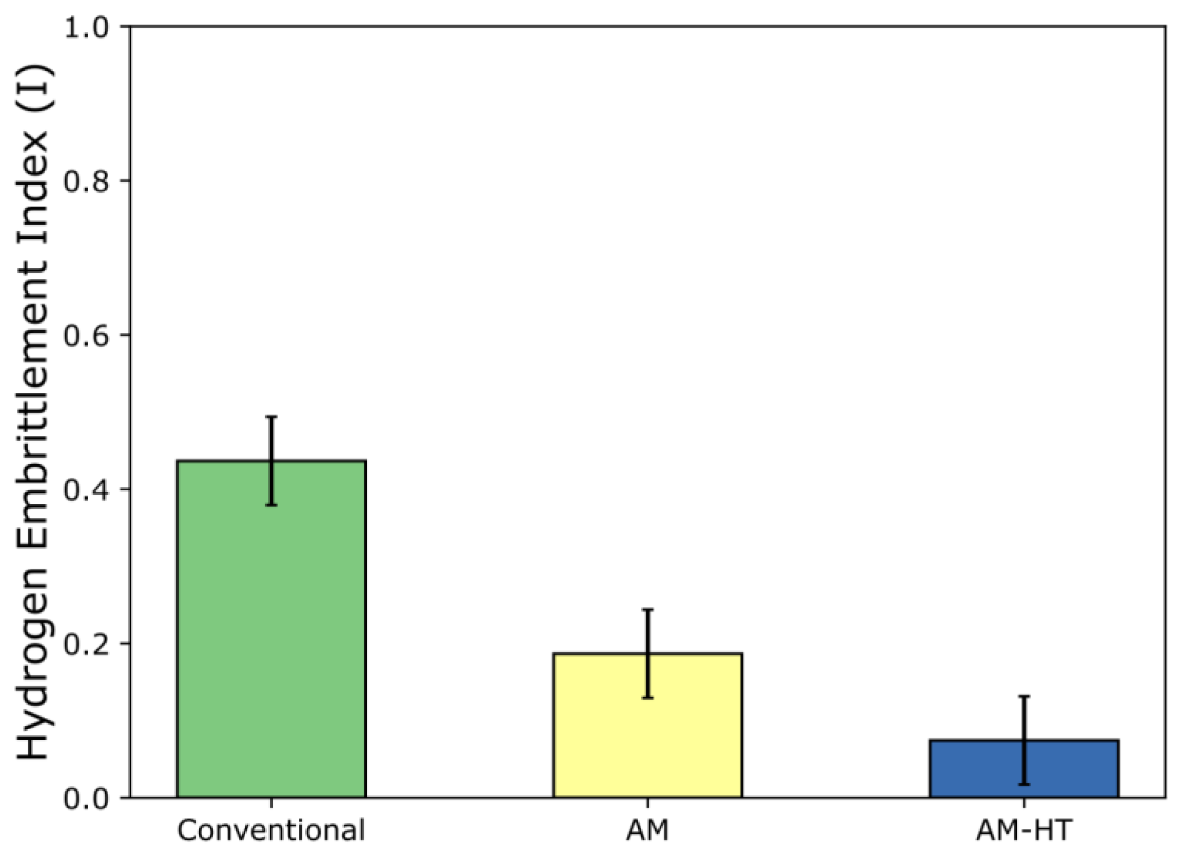
  • The L-PBF Inconel 718 produced from recycled powder shows severe embrittlement in the presence of in-situ gaseous (150 bar) hydrogen. However, in the as-processed state, the degree of embrittlement (HEI) is 50% lower compared to the conventional Inconel 718.
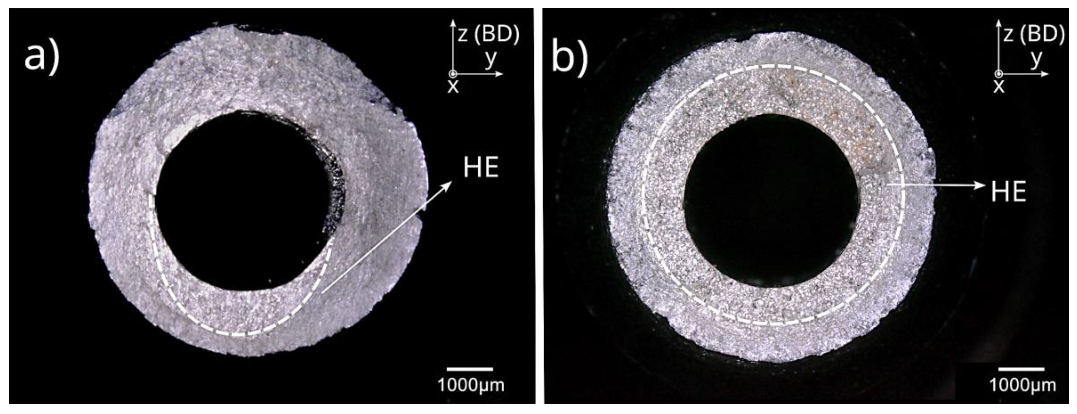
  • L-PBF Inconel 718 was found to have coarse-grained microstructure with columnar grains elongated along the building direction (BD). Microstructural anisotropy with respect to BD was observed in both as-processed and after post-processing heat treatment states. Such anisotropy has led to a narrow hydrogen embrittlement zone along the build direction.
  • Despite the higher yield strength, AM-HT Inconel 718 showed the least degree of hydrogen embrittlement (64% lower than conventional Inconel 718). The better resistance compared to the conventional Inconel 718 could be attributed to the AM-induced microstructural anisotropy. As hydrogen embrittlement occurs only in a narrow region along the build direction, the remainder of the material retains its ductility, unlike the conventional sample where a uniform and wide HE region is observed.
  • The fracture surface of AM Inconel 718 was found to be similar to that of the conventional samples. It can, thus, be expected that the same HE mechanisms is occurring in both conventional and AM samples. For the conventional samples, brittle cleavage facets and presence of dislocation slip lines signifying plasticity were found on the fracture surface. It was concluded that the HE mechanism includes an interplay between HEDE, HELP and AIDE.
To delineate the effect of powder on hydrogen embrittlement, it is recommended to test L-PBF components produced from the conventional Inconel 718 powder. Additionally, in this study it was seen that the unique anisotropy in microstructure is the cause for lower hydrogen embrittlement index of AM-HT samples. This suggests that, with careful design considerations, for L-PBF produced components, properties can be selectively tailored at regions exposed to hydrogen to minimise hydrogen embrittlement.

Author Contributions

Conceptualization, N.K.M., A.G., M.V., T.R., S.P.S. and V.P.; investigation, N.K.M.; writing—original draft preparation, N.K.M.; writing—review and editing, V.P., T.R., S.P.S. and M.V.; supervision, V.P. All authors have read and agreed to the published version of the manuscript.

Funding

This research received no external funding.

Institutional Review Board Statement

Not applicable.

Informed Consent Statement

Not applicable.

Data Availability Statement

The data presented in this study are available in the article.

Conflicts of Interest

The authors declare no conflict of interest.

References

  1. Gibson, I.; Rosen, D.; Stucker, B. Additive Manufacturing Technologies 3D Printing, Rapid Prototyping, and Direct Digital Manufacturing, 2nd ed.; Springer: New York, NY, USA, 2010. [Google Scholar]
  2. Javaid, M.; Haleem, A.; Singh, R.P.; Suman, R.; Rab, S. Role of additive manufacturing applications towards environmental sustainability. Adv. Ind. Eng. Polym. Res. 2021, 4, 312–322. [Google Scholar] [CrossRef]
  3. Bhowmik, S.; McWilliams, B.A.; Knezevic, M. Effect of powder reuse on tensile, compressive, and creep strength of Inconel 718 fabricated via laser powder bed fusion. Mater. Charact. 2022, 190, 112023. [Google Scholar] [CrossRef]
  4. Bjørge, O.K. Mechanical Properties of 316L Stainless Steel Made by Selective Laser Melting Using Powder Produced from Recycled Scrap Material by Vacuum Induction Gas Atomizing. Bachelor’s Thesis, Universitetet i Stavanger, Stavanger, Norway, 2021. [Google Scholar]
  5. Fullenwider, B.; Kiani, P.; Schoenung, J.M.; Ma, K. From Recycled Machining Waste to Useful Powders for Metal Additive Manufacturing; Springer: Cham, Switzerland, 2019; pp. 3–7. [Google Scholar]
  6. Yi, F.; Zhou, Q.; Wang, C.; Yan, Z.; Liu, B. Effect of powder reuse on powder characteristics and properties of Inconel 718 parts produced by selective laser melting. J. Mater. Res. Technol. 2021, 13, 524–533. [Google Scholar] [CrossRef]
  7. Ardila, L.C.; Garciandia, F.; González-Díaz, J.B.; Álvarez, P.; Echeverria, A.; Petite, M.M.; Deffley, R.; Ochoa, J. Effect of IN718 Recycled Powder Reuse on Properties of Parts Manufactured by Means of Selective Laser Melting. Phys. Procedia 2014, 56, 99–107. [Google Scholar] [CrossRef] [Green Version]
  8. Gruber, K.; Smolina, I.; Kasprowicz, M.; Kurzynowski, T. Evaluation of Inconel 718 Metallic Powder to Optimize the Reuse of Powder and to Improve the Performance and Sustainability of the Laser Powder Bed Fusion (LPBF) Process. Materials 2021, 14, 1538. [Google Scholar] [CrossRef]
  9. Sutton, A.T.; Kriewall, C.S.; Leu, M.C.; Newkirk, J.W. Characterization of heat-affected powder generated during the selective laser melting of 304L stainless steel powder. In Proceedings of the Solid Freeform Conference, Austin, TX, USA, 7–9 August 2017; pp. 7–9. [Google Scholar]
  10. Slotwinski, J.A.; Garboczi, E.J.; Stutzman, P.E.; Ferraris, C.F.; Watson, S.S.; Peltz, M.A. Characterization of Metal Powders Used for Additive Manufacturing. J. Res. Natl. Inst. Stand. Technol. 2014, 119, 460. [Google Scholar] [CrossRef]
  11. Sutton, A.T.; Kriewall, C.S.; Karnati, S.; Leu, M.C.; Newkirk, J.W.; Everhart, W.; Brown, B. Evolution of AISI 304L stainless steel part properties due to powder recycling in laser powder-bed fusion. Addit. Manuf. 2020, 36, 101439. [Google Scholar] [CrossRef]
  12. Reed, R.C. Superalloys—Fundamentals and Applications; Cambridge University Press: Cambridge, UK, 2006. [Google Scholar]
  13. Soller, S.; Barata, A.; Beyer, S.; Dahlhaus, A.; Guichard, D.; Humbert, E.; Kretschmer, J.; Zeiss, W. Selective laser melting (SLM) of Inconel 718 and stainless steel injectors for liquid rocket engines. In Proceedings of the Space Propulsion Conference 2016, Roma, Italy, 2–6 May 2016. [Google Scholar]
  14. Zhang, Z.; Obasi, G.; Morana, R.; Preuss, M. Hydrogen assisted crack initiation and propagation in a nickel-based superalloy. Acta Mater. 2016, 113, 272–283. [Google Scholar] [CrossRef] [Green Version]
  15. Liu, L.; Tanaka, K.; Hirose, A.; Kobayashi, K. Effects of precipitation phases on the hydrogen embrittlement sensitivity of Inconel 718. Sci. Technol. Adv. Mater. 2002, 3, 335–344. [Google Scholar] [CrossRef] [Green Version]
  16. Ehrlin, N.; Bjerkén, C.; Fisk, M. Cathodic hydrogen charging of Inconel 718. AIMS Mater. Sci. 2016, 3, 1350–1364. [Google Scholar] [CrossRef]
  17. Lynch, S. Hydrogen embrittlement phenomena and mechanisms. Corros. Rev. 2012, 30, 105–123. [Google Scholar] [CrossRef]
  18. ASTM F2078-22 Red; Standard Terminology Relating to Hydrogen Embrittlement Testing. ASTM International: West Conshohocken, PA, USA, 2016.
  19. Popovich, V.A.; Borisov, E.V.; Popovich, A.A.; Sufiiarov, V.S.; Masaylo, D.V.; Alzina, L. Functionally graded Inconel 718 processed by additive manufacturing: Crystallographic texture, anisotropy of microstructure and mechanical properties. Mater. Des. 2017, 114, 441–449. [Google Scholar] [CrossRef]
  20. DebRoy, T.; Wei, H.L.; Zuback, J.S.; Mukherjee, T.; Elmer, J.W.; Milewski, J.O.; Beese, A.M.; Wilson-Heid, A.; De, A.; Zhang, W. Additive manufacturing of metallic components—Process, structure and properties. Prog. Mater. Sci. 2018, 92, 112–224. [Google Scholar] [CrossRef]
  21. Brenne, F.; Taube, A.; Pröbstle, M.; Neumeier, S.; Schwarze, D.; Schaper, M.; Niendorf, T. Microstructural design of Ni-base alloys for high-temperature applications: Impact of heat treatment on microstructure and mechanical properties after selective laser melting. Prog. Addit. Manuf. 2016, 1, 141–151. [Google Scholar] [CrossRef] [Green Version]
  22. Schneider, J.; Lund, B.; Fullen, M. Effect of heat treatment variations on the mechanical properties of Inconel 718 selective laser melted specimens. Addit. Manuf. 2018, 21, 248–254. [Google Scholar] [CrossRef]
  23. Gallmeyer, T.G.; Moorthy, S.; Kappes, B.B.; Mills, M.J.; Amin-Ahmadi, B.; Stebner, A.P. Knowledge of process-structure-property relationships to engineer better heat treatments for laser powder bed fusion additive manufactured Inconel 718. Addit. Manuf. 2020, 31, 100977. [Google Scholar] [CrossRef]
  24. Liu, P.; Hu, J.; Sun, S.; Feng, K.; Zhang, Y.; Cao, M. Microstructural evolution and phase transformation of Inconel 718 alloys fabricated by selective laser melting under different heat treatment. J. Manuf. Process. 2019, 39, 226–232. [Google Scholar] [CrossRef]
  25. Merson, E.; Myagkikh, P.; Poluyanov, V.; Dorogov, M.; Merson, D.; Vinogradov, A. The fundamental difference between cleavage and hydrogen-assisted quasi-cleavage in ferritic materials revealed by multiscale quantitative fractographic and side surface characterization. Mater. Sci. Eng. A 2021, 824, 141826. [Google Scholar] [CrossRef]
  26. Lynch, S.P. Progress towards understanding mechanisms of hydrogen embrittlement and stress corrosion cracking. In Proceedings of the CORROSION 2007, Nashville, TN, USA, 11–15 March 2007. [Google Scholar]
  27. Nagumo, M. Fundamentals of Hydrogen Embrittlement; Springer: Singapore, 2016; Volume 921. [Google Scholar]
  28. Hicks, P.D.; Altstetter, C.J. Hydrogen-enhanced cracking of superalloys. Metall Trans. A 1992, 23, 237–249. [Google Scholar] [CrossRef]
  29. Fournier, L.; Delafosse, D.; Magnin, T. Cathodic hydrogen embrittlement in alloy 718. Mater. Sci. Eng. A 1999, 269, 111–119. [Google Scholar] [CrossRef]
  30. Lee, D.-H.; Zhao, Y.; Lee, S.Y.; Ponge, D.; Jägle, E.A. Hydrogen-assisted failure in Inconel 718 fabricated by laser powder bed fusion: The role of solidification substructure in the embrittlement. Scr. Mater. 2022, 207, 114308. [Google Scholar] [CrossRef]
  31. Li, X.; Li, Q.; Wang, T.; Zhang, J. Hydrogen-assisted failure of laser melting additive manufactured IN718 superalloy. Corros. Sci. 2019, 160, 108171. [Google Scholar] [CrossRef]
  32. Aiello, F.; Beghini, M.; Bertini, L.; Macoretta, G.; Monelli, B.D.; Valentini, R. Hydrogen diffusivity and tensile properties degradation in SLMed Inconel 718. IOP Conf. Ser. Mater. Sci. Eng. 2022, 1214, 012002. [Google Scholar] [CrossRef]
  33. Hesketh, J.; McClelland, N.; Zhang, Y.; Green, C.; Turnbull, A. Influence of additive manufacturing by laser powder bed fusion on the susceptibility of Alloy 718 to hydrogen embrittlement. Corros. Eng. Sci. Technol. 2021, 56, 565–574. [Google Scholar] [CrossRef]
  34. F3nice. Available online: https://f3nice.com/ (accessed on 1 October 2022).
  35. ASTM F3055-14a; Standard Specification for Additive Manufacturing Nickel Alloy (UNS N07718) with Powder Bed Fusion. ASTM International: West Conshohocken, PA, USA, 2021.
  36. Nagumo, M. Characteristic Features of Deformation and Fracture in Hydrogen Embrittlement. In Fundamentals of Hydrogen Embrittlement; Springer: Singapore, 2016; pp. 137–165. [Google Scholar]
  37. AMS5663N; Nickel Alloy, Corrosion and Heat-Resistant, Bars, Forgings, and Rings 52.5Ni–19Cr–3.0Mo–5.1Cb (Nb)–0.90Ti–0.50Al–18Fe Consumable Electrode or Vacuum Induction Melted 1775 °F (968 °C) Solution and Precipitation Heat Treated. SAE International: Warrendale, PA, USA, 2016.
  38. VDM Metals GmbH. Available online: https://www.vdm-metals.com/en/ (accessed on 1 October 2022).
  39. ASTM B637-18; Book of Standards vol. 02.04. ASTM International: West Conshohocken, PA, USA, 2018.
  40. Boot, T.; Riemslag, T.A.C.; Reinton, E.T.E.; Liu, P.; Walters, C.L.; Popovich, V. In-Situ Hollow Sample Setup Design for Mechanical Characterisation of Gaseous Hydrogen Embrittlement of Pipeline Steels and Welds. Metals 2021, 11, 1242. [Google Scholar] [CrossRef]
  41. Ganji, D.K.; Rajyalakshmi, G. Influence of Alloying Compositions on the Properties of Nickel-Based Superalloys: A Review. In Lecture Notes in Mechanical Engineering; Springer: Singapore, 2020; pp. 537–555. [Google Scholar]
  42. Cai, D.; Zhang, W.; Nie, P.; Liu, W.; Yao, M. Dissolution kinetics of delta phase and its influence on the notch sensitivity of Inconel 718. Mater. Charact. 2007, 58, 220–225. [Google Scholar] [CrossRef]
  43. Li, X.; Shi, J.J.; Wang, C.H.; Cao, G.H.; Russell, A.M.; Zhou, Z.J.; Li, C.P.; Chen, G.F. Effect of heat treatment on microstructure evolution of Inconel 718 alloy fabricated by selective laser melting. J. Alloy. Compd. 2018, 764, 639–649. [Google Scholar] [CrossRef]
  44. Chlebus, E.; Gruber, K.; Kuźnicka, B.; Kurzac, J.; Kurzynowski, T. Effect of heat treatment on the microstructure and mechanical properties of Inconel 718 processed by selective laser melting. Mater. Sci. Eng. A 2015, 639, 647–655. [Google Scholar] [CrossRef]
  45. Zhang, D.; Niu, W.; Cao, X.; Liu, Z. Effect of standard heat treatment on the microstructure and mechanical properties of selective laser melting manufactured Inconel 718 superalloy. Mater. Sci. Eng. A 2015, 644, 32–40. [Google Scholar] [CrossRef]
  46. Sabelkin, V.P.; Cobb, G.R.; Shelton, T.E.; Hartsfield, M.N.; Newell, D.J.; O’Hara, R.P.; Kemnitz, R.A. Mitigation of anisotropic fatigue in nickel alloy 718 manufactured via selective laser melting. Mater. Des. 2019, 182, 108095. [Google Scholar] [CrossRef]
  47. Wang, L.Y.; Zhou, Z.J.; Li, C.P.; Chen, G.F.; Zhang, G.P. Comparative investigation of small punch creep resistance of Inconel 718 fabricated by selective laser melting. Mater. Sci. Eng. A 2019, 745, 31–38. [Google Scholar] [CrossRef]
  48. Popovich, V.A.; Borisov, E.V.; Popovich, A.A.; Sufiiarov, V.S.; Masaylo, D.V.; Alzina, L. Impact of heat treatment on mechanical behaviour of Inconel 718 processed with tailored microstructure by selective laser melting. Mater. Des. 2017, 131, 12–22. [Google Scholar] [CrossRef]
  49. Hosseini, E.; Popovich, V.A. A review of mechanical properties of additively manufactured Inconel 718. Addit. Manuf. 2019, 30, 100877. [Google Scholar] [CrossRef]
  50. Trosch, T.; Strößner, J.; Völkl, R.; Glatzel, U. Microstructure and mechanical properties of selective laser melted Inconel 718 compared to forging and casting. Mater. Lett. 2016, 164, 428–431. [Google Scholar] [CrossRef]
  51. Zhang, P.; Li, S.; Zhang, Z. General relationship between strength and hardness. Mater. Sci. Eng. A 2011, 529, 62. [Google Scholar] [CrossRef]
  52. Caiazzo, F.; Alfieri, V.; Casalino, G. On the Relevance of Volumetric Energy Density in the Investigation of Inconel 718 Laser Powder Bed Fusion. Materials 2020, 13, 538. [Google Scholar] [CrossRef] [Green Version]
  53. Rezende, M.C.; Araujo, L.S.; Gabriel, S.B.; dos Santos, D.S.; de Almeida, L.H. Hydrogen embrittlement in nickel-based superalloy 718: Relationship between γ′ + γ″ precipitation and the fracture mode. Int. J. Hydrogen Energy 2015, 40, 17075–17083. [Google Scholar] [CrossRef]
  54. Zhang, D.; Feng, Z.; Wang, C.; Wang, W.; Liu, Z.; Niu, W. Comparison of microstructures and mechanical properties of Inconel 718 alloy processed by selective laser melting and casting. Mater. Sci. Eng. A 2018, 724, 357–367. [Google Scholar] [CrossRef]
  55. Zhang, Z.; Obasi, G.; Morana, R.; Preuss, M. In-situ observation of hydrogen induced crack initiation in a nickel-based superalloy. Scr. Mater. 2017, 140, 40–44. [Google Scholar] [CrossRef]
  56. Sundararaman, M.; Mukhopadhyay, P.; Banerjee, S. Deformation behaviour of γ″ strengthened inconel 718. Acta Metall. 1988, 36, 847–864. [Google Scholar] [CrossRef]
  57. Janssen, M.; Zuidema, J.; Wanhill, R. Fracture Mechanics; CRC Press: Boca Raton, FL, USA, 2004. [Google Scholar]
  58. Lin, J.; Chen, F.; Liu, F.; Xu, D.; Gao, J.; Tang, X. Hydrogen permeation behavior and hydrogen-induced defects in 316L stainless steels manufactured by additive manufacturing. Mater. Chem. Phys. 2020, 250, 123038. [Google Scholar] [CrossRef]
  59. Tarzimoghadam, Z.; Ponge, D.; Klöwer, J.; Raabe, D. Hydrogen-assisted failure in Ni-based superalloy 718 studied under in situ hydrogen charging: The role of localized deformation in crack propagation. Acta Mater. 2017, 128, 365–374. [Google Scholar] [CrossRef]
Figure 1. SEM micrographs of (a) recycled Inconel 718 powder particles, (b) high magnification image showing satellite particles on the surface.
Metals 13 00418 g001
Figure 2. (a) Sample orientation (horizontal) for the L-PBF process, (b) AM samples. z-axis is the building direction (BD) and x-axis is the tensile axis.
Metals 13 00418 g002
Figure 3. (a) Sample dimensions. (b) Test setup for SSRT. The tensile loading direction is the x-axis.
Metals 13 00418 g003
Figure 4. (a) Optical image of conventional Inconel 718 showing equiaxed grains. (b) SEM image showing δ phase.
Metals 13 00418 g004
Figure 5. (a) Meltpool boundaries of AM-AP samples. (b) Cellular substructures with segregations along the boundaries in yz-plane.
Metals 13 00418 g005
Figure 6. (a) Optical microscopy and (b) SEM in yz-plane showing microstructure of AM-HT samples.
Metals 13 00418 g006
Figure 7. Microstructure of AM samples in the xy-plane (a) AM-AP (b) AM-HT.
Metals 13 00418 g007
Figure 8. XRD measurement results for Conventional, AM-AP and AM-HT Inconel 718.
Metals 13 00418 g008
Figure 9. Vickers hardness measurements in yz-plane of conventional, AM-AP and AM-HT Inconel 718.
Metals 13 00418 g009
Figure 10. Representative images of porosity for (a) Conventional and (b) AM Inconel 718.
Metals 13 00418 g010
Figure 11. Representative SSRT curves for conventional, AM-AP and AM-HT Inconel 718.
Metals 13 00418 g011
Figure 12. HE indexes of conventional, AM-AP and AM-HT Inconel 718 samples.
Metals 13 00418 g012
Figure 13. (a) Zoomed-out and (b) zoomed-in view showing characteristic ductile fracture with micro-voids in conventional Inconel 718 tested in nitrogen.
Metals 13 00418 g013
Figure 14. Fracture surface of AM-AP tested in nitrogen at 150 bar. (a) Low magnification. (b) High magnification.
Metals 13 00418 g014
Figure 15. Three distinct regions on the fracture surface of conventional samples tested in hydrogen in-situ condition. (a) low magnification (b) high magnification at region of intergranular failure.
Metals 13 00418 g015
Figure 16. Slip lines along the brittle facets of in-situ hydrogen embrittled samples.
Metals 13 00418 g016
Figure 17. Cross-sectional image of fracture surface showing different modes of failure in conventional Inconel 718.
Metals 13 00418 g017
Figure 18. Hydrogen embrittled fracture region in AM-AP sample. (a) Low magnification. (b) High magnification of marked region.
Metals 13 00418 g018
Figure 19. Hydrogen embrittled fraction region in AM-HT sample. (a) Low magnification. (b) High magnification of marked region.
Metals 13 00418 g019
Figure 20. (a) Anisotropy in the HE region of AM samples. (b) Homogeneous embrittled region in conventional sample. X-axis is the tensile loading direction and z-axis is the build direction.
Metals 13 00418 g020
Figure 21. Microstructure in the fracture plane for (a) Conventional Inconel 718 showing equiaxed grains, (b) AM-HT showing elongated grains. As AM-HT clearly shows elongated grains without meltpools, it is used as the representative image for all AM samples.
Metals 13 00418 g021
Figure 22. (a) Schematic of L-PBF sample showing area of interest (notch). (b) Cross-sectional view of the notch. (c) Crack propagation in xy-plane. (d) Crack propagation in xz-plane. z-axis is the build direction (BD) and x-axis is the tensile axis. The microstructure schematic is not to scale.
Metals 13 00418 g022
Figure 23. High magnification image of grain like features on the fracture surface of AM samples. (a) AM-AP showing continuous structures. (b) AM-HT showing discontinuous structures.
Metals 13 00418 g023
Table 1. Process parameters used for L-PBF of Inconel 718.
Laser Power
(W)
Scan Speed
(mm/s)
Hatch Distance
(mm)
Layer Thickness
(µm)
Volumetric Energy Density (VED)
(J/mm3)
285960804067
Table 2. Post-processing heat treatment parameters used for the Inconel 718 samples.
SampleHeat TreatmentTemperatureHolding TimeCooling
ConventionalSolutionising1032 °C1 hWC
Ageing790 °C6 hAC
AM-HT *Solutionising980 °C1 hAC
Ageing720 °C8 hFC to 620 °C @ 55 °C/h
620 °C8 hAC
* As per AMS5663 [37].
Table 3. Composition (wt. %) of Inconel 718 obtained from X-ray fluorescence spectroscopy (XRF).
SampleNiCrFeNbMoTiAlSiMnMgVCoCu
Conventional54.9017.5517.554.662.860.940.450.090.09-0.030.370.15
AM54.8418.2517.404.713.011.090.360.120.110.050.02--
Table 4. In-situ slow strain rate testing (SSRT) results.
SampleEnvironment *Y.S.
(MPa)
UTS
(MPa)
Elongation to Failure (%)RA
(%)
ConventionalNitrogen1069 ± 41474 ± 2812.7 ± 1.430.6 ± 1.4
Hydrogen1059 ± 341308 ± 015.8 ± 0.117.2 ± 2.1
AM-APNitrogen898 ± 111129 ± 117.5 ± 0.124.0 ± 1.3
Hydrogen897 ± 121153 ± 055.4 ± 0.119.5 ± 0.6
AM-HTNitrogen1462 ± 081776 ± 074.5 ± 0.311.7 ± 1.8
Hydrogen1409 ± 101610 ± 032.8 ± 0.210.8 ± 0.3
* Nitrogen and hydrogen testing were performed in in-situ condition with 150 bar and 25 °C. For hydrogen testing, an additional 48 h charging was performed at 25 °C.
Disclaimer/Publisher’s Note: The statements, opinions and data contained in all publications are solely those of the individual author(s) and contributor(s) and not of MDPI and/or the editor(s). MDPI and/or the editor(s) disclaim responsibility for any injury to people or property resulting from any ideas, methods, instructions or products referred to in the content.

