Article

The Microstructural Degradation of Ni-Based Superalloys with Segregation under the Super-Gravity Condition

1
Beijing Key Laboratory of Microstructure and Property of Advanced Materials, Faculty of Materials and Manufacturing, Beijing University of Technology, Beijing 100124, China
2
State Key Laboratory of Silicon Materials, Department of Materials Science and Engineering, Zhejiang University, Hangzhou 310058, China
*
Author to whom correspondence should be addressed.
These authors contributed equally to this work.
Metals 2023, 13(2), 416; https://doi.org/10.3390/met13020416
Submission received: 18 January 2023 / Revised: 8 February 2023 / Accepted: 15 February 2023 / Published: 17 February 2023
(This article belongs to the Special Issue Metal Plasticity and Deformation Mechanism of Metallic Materials)

Abstract

:
The Ni-based superalloy is used as the turbine blade, which is subject to the coupling effect of temperature and super-gravity during service. As the Ni-based superalloys are difficult to become homogenous after using the solid solution heat treatment, a study on morphology and composition distribution of Ni-base superalloys with segregation during microstructural degradation is necessary. This study investigates the microstructure of the ex-service turbine blade and cast samples subjected to the high-temperature centrifugal test. The difference in the size and shape factor of the γ′ phase decreased with the stress caused by the super-gravity condition, indicating a higher magnitude of homogenization degree. The higher stress will also promote the merge of the sub-grain boundaries, leading to a lower density and higher orientational deviation of the sub-grain boundaries.

1. Introduction

Ni-based superalloy has excellent high-temperature performance and is critical for preparing aero-engine blades [1,2,3,4,5]. At present, the primary methods of preparing Ni-based superalloy blades are directional solidification and advanced precision casting [6,7,8]. However, the solidification process is often uneven. Due to the complex system with about ten elements of Ni-based superalloys, the dendritic structure with eutectic and carbide in the inter-dendrite will generate in the cast microstructure [5,9]. Heat treatment is usually adopted to eliminate uneven microstructure. The heat treatment mainly includes two aspects, i.e., the solution and aging treatments [10,11,12,13]. The solution treatment can dissolve the eutectic and carbide, eliminate element segregation, and achieve the purpose of uniform alloy composition [13,14,15,16]. The aging treatment is mainly to adjust the size, shape, and volume fraction of the γ′ strengthening phase [17,18]. However, the dendrite segregations are difficult to completely eliminate [12,13,19]. The uneven structure will affect the service life of the blades as it is usually the nucleation site for low-angle boundaries. Therefore, studying the evolution law of these structures with dendrite segregation under super-gravity and high-temperature conditions is necessary.
Currently, the study on the microstructural degradation in the turbine blade of Ni-based superalloy mainly focuses on the coarsening of γ′ phase, the distribution of dislocations, the decomposition of MC carbide, and the precipitation of the topological close-packed (TCP) phase [20,21,22]. The γ′ phase will coarsen under high temperature, and directional coarsen, i.e., raft, under high temperature and stress [22,23,24]. Its evolution rate is sensitive to the external condition, thus exhibiting inhomogeneous distribution in the turbine blade. The researchers also use the evolution rate of γ′ phase to derive the complex temperature distribution and stress distribution [25]. For example, the blade’s trailing edge is usually referred to in the high-temperature region as the raft formation [22,25]. The distribution of dislocations is also inhomogeneous in the blade [20,26]. Its density increases from the top to the bottom of the blade. This is due to the increase in stress caused by the super-gravity condition. The elements’ enrichment will lead to the decomposition of MC carbide, forming the M6C or M23C6 carbides, which contain a higher magnitude of solid solution elements [20,21]. In addition, the TCP phase, such as μ and P phases, will also precipitate for local supersaturation [21,22].
The inhomogeneous distribution of the microstructural degradation will change the diffusion process and thus change the segregation of the alloy [27,28]. However, studies on microstructural degradation of Nickel-based superalloys with segregation under the super-gravity condition are still lacking. In this study, the ex-service turbine blade and cast samples are selected to investigate their microstructural degradation under the super-gravity condition.

2. Materials and Methods

The ex-service turbine blade was taken from aircraft engines that had undergone service exposure of about 10,000 h engine operating. In previous studies, the shank section was considered the original alloy because of its low service temperature and almost no significant changes in microstructure [23,29,30,31]. The chemical composition of the shank section was analyzed, as shown in Table 1. Two sections were selected for the top and bottom of the blade to check its microstructural degradation.
The high-temperature centrifugal test was also performed by using the super-gravity equipment device. The constant temperature zones of the specimens are at the rotational radius of 114~134 mm. The test temperature was 950 °C. The rotational speed is 19,000 rpm, corresponding to 45,000~53,000 g in the constant temperature zones (calculated by Formula (1)), which is consistent with the centrifugal acceleration in the real blade. Based on Formula (2) [30,32], the stress in the test specimen is calculated to be about 2 MPa at the top and 80 MPa at the bottom. The specimens were subjected to the super-gravity experiment at 950 °C for 30 h, and an aging treatment at 950 °C for 30 h without stress was also performed as a control group. After the test at 950 °C, the specimens were further heat-treated at 1350 °C for 6 h.
a = ω 2 r = ( 2 π T ) 2 r
which a is the centrifugal acceleration,   ω is the angular velocity of rotation, r is the radius of rotation, the value of r ranges from 0.114 to 0.134 m, T is the period of rotation.
σ ( x ) = ω 2 ρ x R 0 ξ d ξ = ω 2 ρ 2 ( R 0 2 x 2 )
which σ ( x ) is the stress at the position x from the center of the rotation axis, ω is the angular velocity of rotation, ρ is the density of the alloy, ξ is the distance of any section on the blade from the center of the rotating shaft, d ξ is a micro-segment of length d ξ at a distance ξ from the center point of the axis of rotation, R 0 is the total length of the test specimen. In this experiment, ρ is 8100 kg/m3, ω is 1994 rad/s, R 0 is 0.134 m, the value of x ranges from 0.114 to 0.134 m.
The microstructural examinations were performed by a field-emission scanning electron microscope (SEM, FEI-Quanta 650F, Thermo Fisher Scientific, Waltham, MA, USA). Some characteristic parts, such as inter-dendrite and dendritic stem, were represented by transmission electron microscope (TEM, FEI-Talos, 200 kV, Thermo Fisher Scientific, Waltham, MA, USA). SEM and TEM specimens were extracted by means of electrical discharge machining from the central region. Specimens were extracted in both (001) and (010) planar orientations. The SEM specimens were chemically etched in a solution of 5 g CuSO4, 20 mL HCl and 100 mL H2O. The TEM specimens were polished by means of twin-jet electrochemical polishing in an electrolyte solution containing 5% perchloric acid and 95% ethanol at −30 °C. The Focused ion beam (FIB, FEI-Helios Nanolab 600i, Thermo Fisher Scientific, Waltham, MA, USA) was used to extract TEM samples from characteristic sites.
The microstructure characteristics, such as equivalent diameter and shape factor, were extracted from SEM images. The size of the field of view of the images used for analysis was approximately 3.8 μm × 2.6 μm, and the number of γ′ analyzed was about 200. The final value was obtained by the gauss fitting of the frequency distribution of equivalent diameter. The final value of the shape factor was obtained by calculating the average value. The element distribution of the characteristic region was analyzed by TEM equipped with an EDS detector. EDS analysis was carried out at five different positions in the dendritic stem and inter-dendrite of the blade and the shank. The element contents at the five positions were averaged and compared to obtain the segregation coefficient.

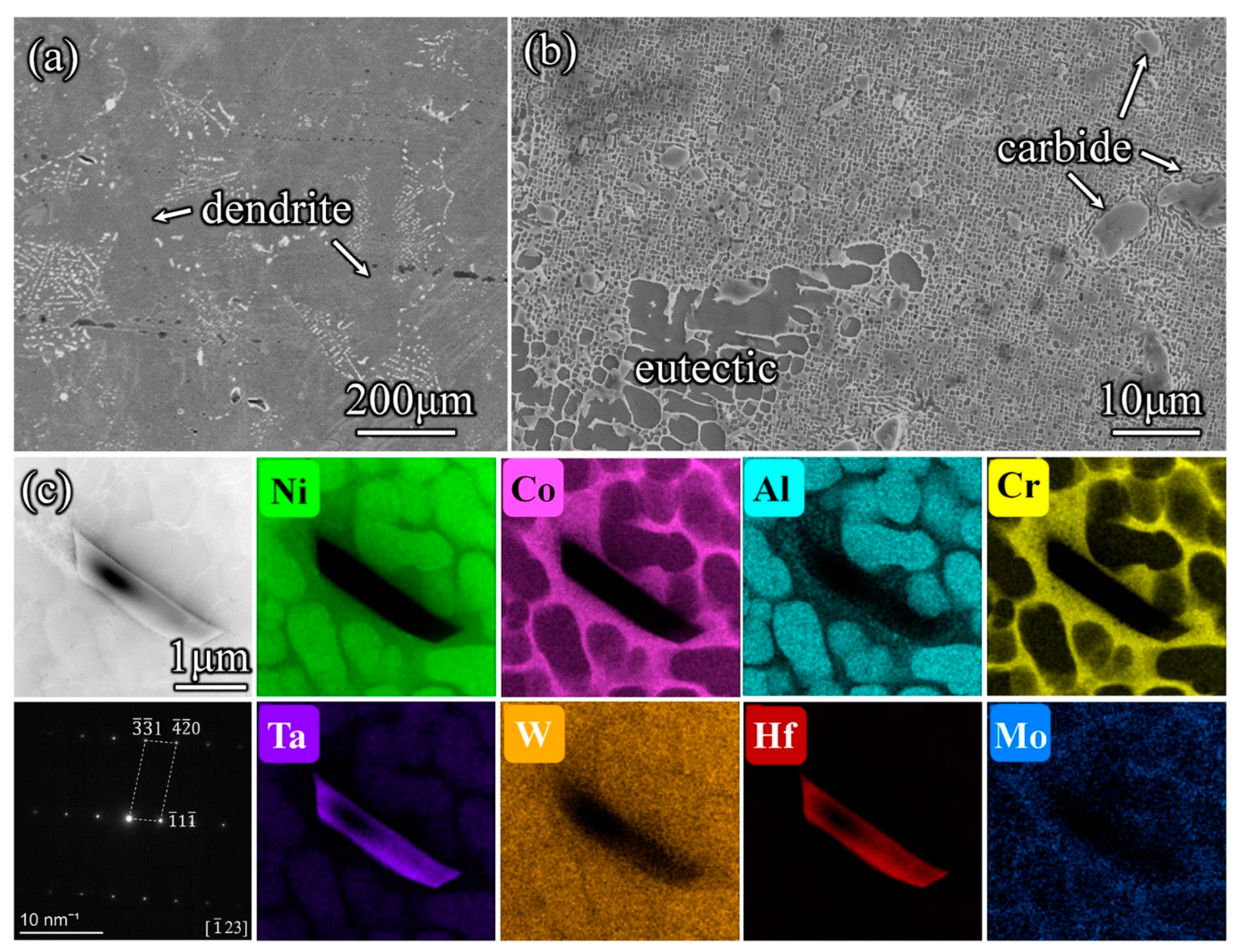
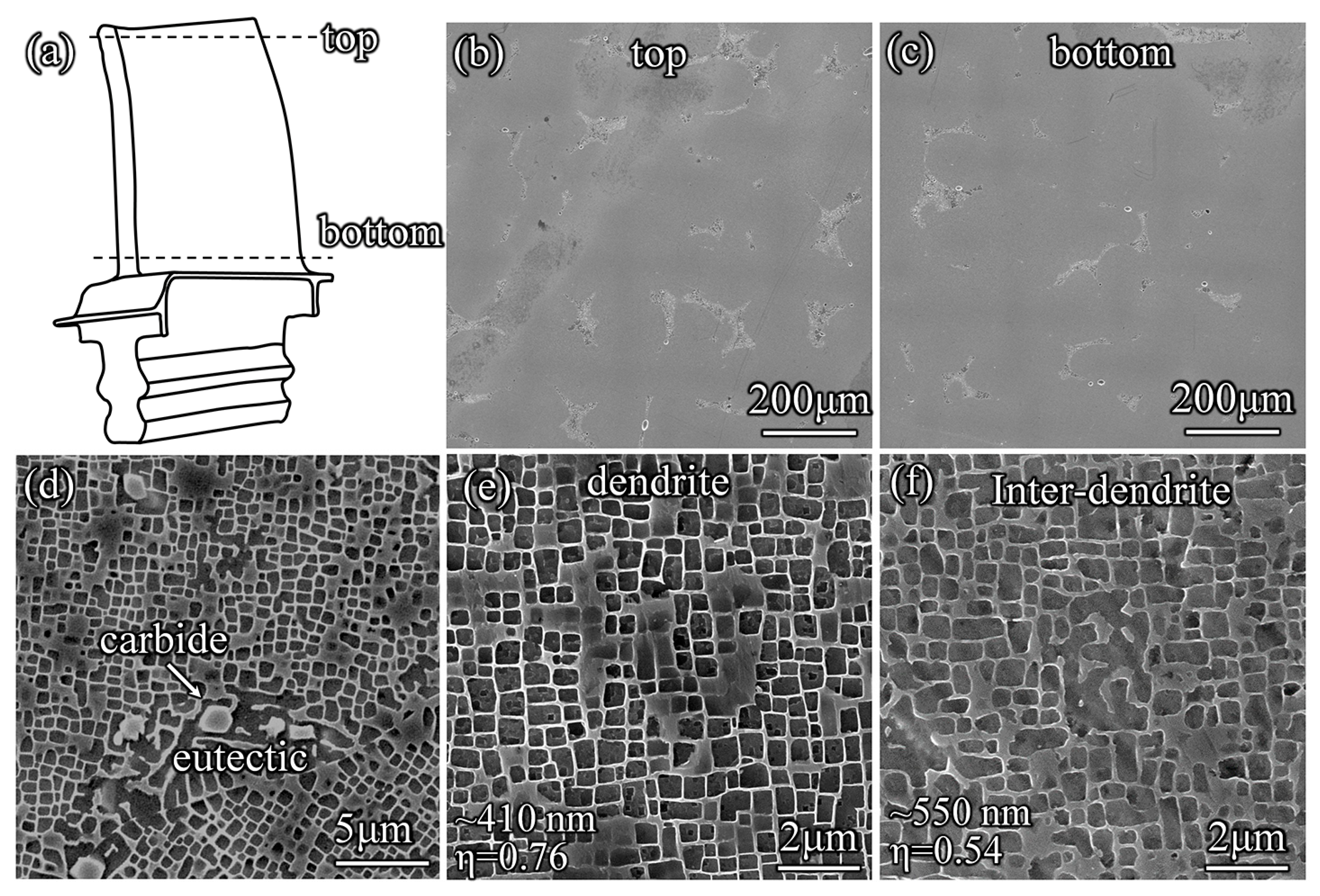
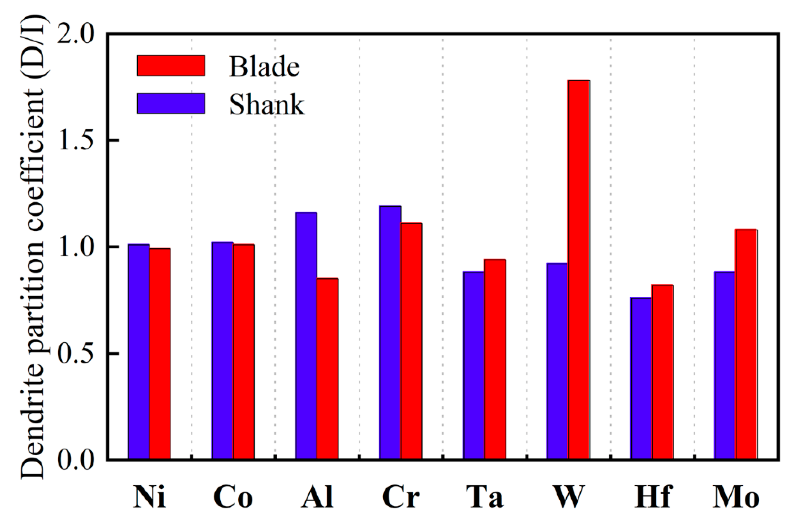
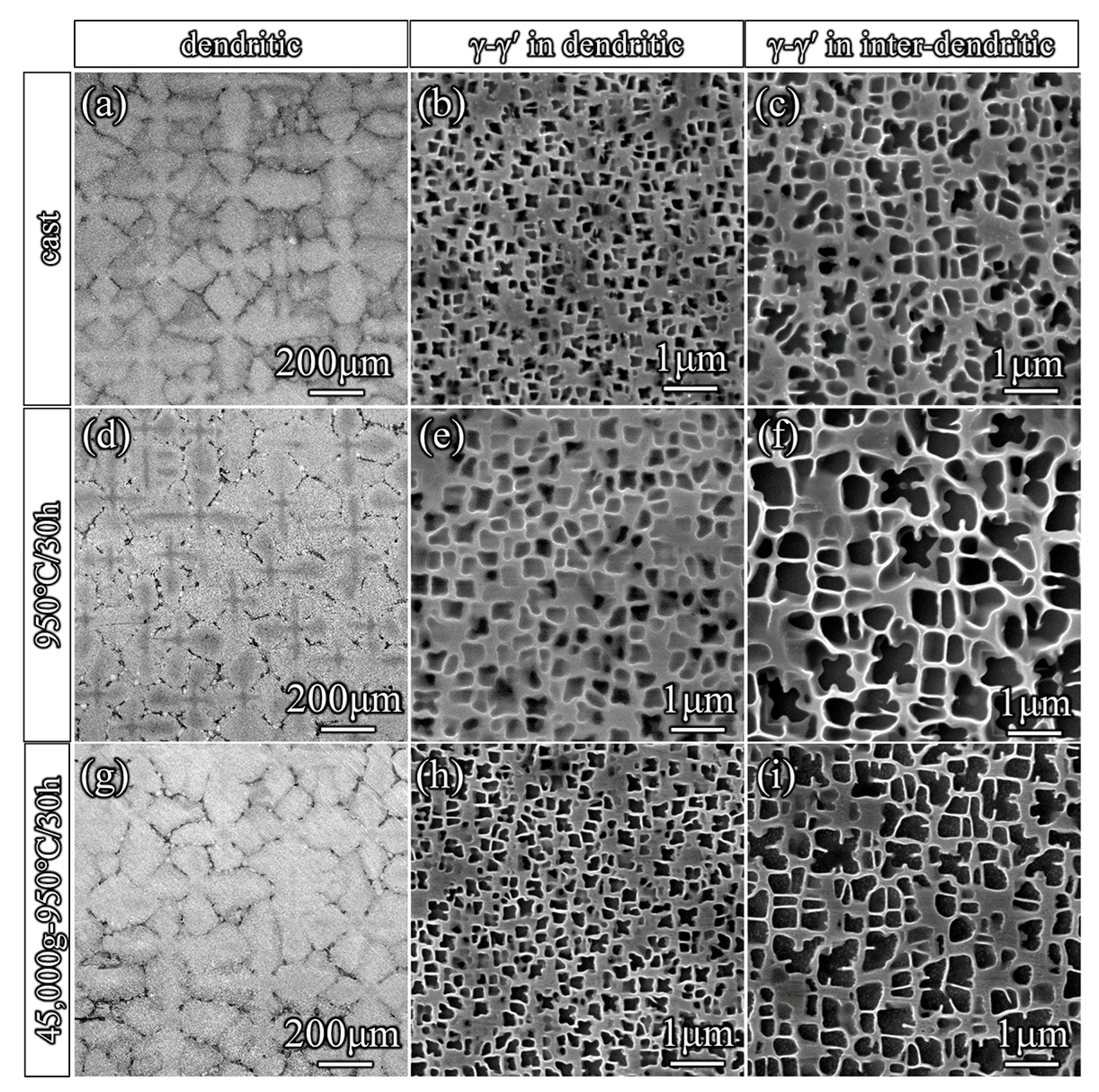
3. Results and Discussion

Figure 1 shows the microstructure of the shank section. During the experiment, the observation direction was the [001] direction. The prominent dendrite structure can be seen in Figure 1a, demonstrating that dendrite segregation is difficult to eliminate completely. In the figure, the white contrast structure is carbide. Since most of the carbide precipitates are in the inter-dendrite region, carbide distribution outlines the blade’s dendrite structure. The typical microstructures of the shank consist of γ matrix and cube-shaped γ′ precipitates. The square structure of the dark contrast in Figure 1b is the γ′ phase, and the light structure surrounding the dark square is the γ phase. Further microscopic characterization of the inter-dendritic structure shows a large number of eutectic and massive carbides, as indicated by arrows in Figure 1b. The eutectic is also composed of γ and γ′ phases, but because the inter-dendrite region of the formed eutectic has more γ′ phase forming elements, the size of γ′ phase in the eutectic region is significantly higher than that of the surrounding dendrite structure. In order to identify the type of carbide, bulk samples were extracted through FIB, and phase analysis was performed, as shown in Figure 1c. Based on the composition distribution map of carbides, it was found that they were enriched in Ta and Hf elements. Through the carbide SAED diagram of calibration, the diffraction spectrum was indicated to the face-centered cubic with the lattice parameter of a = 0.457 nm in [ 1 ¯ 23 ] direction. Finally, it was determined that the carbide is MC type of carbide which is common in cast superalloy [33,34].
In order to quantitatively characterize the difference of γ′ phase in dendrite structure, the structure of the shank section was analyzed, as shown in Figure 2. The observation direction was the [001] direction. Figure 2a,b shows the morphology and composition distribution of the dendritic stem and inter-dendrite, respectively. It can be seen that the γ′ phase structure in the dendritic stem region is squarer and neater, while the γ′ phase in the inter-dendrite region is obviously more irregular. It was found that the average size of γ′ phase in the dendritic stem (~350 nm) was nearly half of that in the inter-dendrite γ′ phase (~600 nm) after statistics. The cubed degree of the shape of the γ′ phase is usually described by the form factor (η), which is determined by dividing the largest square side length (a) by the side length (b) of γ′ phase, as shown in the attached picture. Based on this method, the shape factors of the dendritic stem and inter-dendrite γ′ phase are 0.79 and 0.15, respectively. The distribution of the compositions between dendritic stem and inter-dendrite is almost the same. It can be seen from the figure that Ni, Al, Ta, and Hf elements are enriched in γ′ phase, while Co, Cr, Mo, and W elements are enriched in γ phase.
After a long time of super-gravity, the microstructure of the blades changed. This is shown in the microstructure of the blade in Figure 3. Figure 3a is the schematical image of the blade, the top and bottom of the blades are selected as the observation zones. Figure 3b,c shows the dendrite structure at the blade’s top and bottom after service, respectively. The observation direction was the [001] direction. The light contrast structure in the figure is the inter-dendrite eutectic structure. It is obvious that after service, the outline of the intergranular structure becomes unclear, the distribution of bright carbide among dendrites decreases, and there is a small amount of eutectic structure. Figure 3d shows that a small amount of eutectic structure and carbide still exist in the blade after service. Further analysis was conducted on the blade base microstructure after service, as shown in Figure 3e,f. The average size of γ′ phase in the dendritic stem is about 410 nm, and the shape factor is 0.88. The average size of γ′ phase in inter-dendrites is 550 nm, and the shape factor is 0.54. Compared with the morphology and size of γ′ phase between the shank and blade, it can be found that the γ′ phase of the dendritic stem in the blade is coarsened, and the shape factor is slightly decreased. In addition, the size of γ′ phase of the inter-dendrite in the blade is smaller, and the shape factor is significantly increased, indicating that the difference in the shape and size of γ′ phase between the inter-dendrite and the dendritic stem is reduced.
In order to further compare the composition difference between the shank and service blade, the dendritic stem and inter-dendrite composition of the blade were analyzed accordingly. The segregation coefficient was quantitatively characterized by comparing the average composition in the blade and shank cross-sections. As shown in Figure 4, the comparison of the composition segregation coefficient between the dendritic stem and inter-dendrite of the shank and blade is given. In the figure, the segregation coefficients of Ni, Co, Al, Cr, Ta, and Hf elements do not change much, indicating that the super-gravity environment weakens the segregation and homogenization of the above elements. The separation coefficient of W and Mo heavy elements in the blade was higher than that in the shank, indicating that the heavy elements in the inter-dendrite diffused into the dendritic stem. This indicates that the dendrite segregation of the blade can only be partially reduced, although the morphology is relatively uniform.
Through the comprehensive analysis of the blade in service, it is known that the homogenization of the morphology can be promoted. However, the effect of the super-gravity on the microstructural degradation is still unknown as the distribution of the temperature in the blade is inhomogeneous. Therefore, the high-temperature centrifugal test was performed. Figure 5 shows the microstructures of the cast, aging, and super-gravity treatment specimens. The observation direction was the [001] direction. Figure 5a–c shows the cross-sections of the cast specimen. The cast microstructure in Figure 5a consists of the cross-shaped dendrite in light contrast and the surrounding inter-dendrite in dark contrast. Figure 5b,c shows the enlarged microstructure in the dendrite and inter-dendrite regions. The γ and γ′ phases can be recognized, and the size of γ′ is much larger in the inter-dendrite. The magnitude of the difference in the size of γ′ phase is about ~5 times. Figure 5d–f shows the aging treatment specimen at 950 °C for 30 h without stress. The “black cross” contrast appeared in the dendritic stem of the dendrite structure after aging, as shown in Figure 5d. Figure 5e,f shows the microstructures of dendrites and inter-dendrite regions in high magnification. By comparison, the size of γ′ phase in the inter-dendrite is about 4~5 times higher than the size in the dendrite. Figure 5g–i shows the microstructure in the bottom of the super-gravity treatment specimen at 950 °C for 30 h with 85 MPa stress. The dendrite morphology is still clearly visible in the dendrite section shown in Figure 5g. In Figure 5h,i, the size difference of γ′ phase decreases significantly, and the measurement statistics show that the size difference is about 2~3 times. This indicates that the homogenization effect is improved in the process of super-gravity treatment.
The specimens were further heat-treated at 1350 °C for 6 h, and the microstructure is shown in Figure 6. Figure 6a,b shows the aging specimen’s microstructure in the dendritic stem and inter-dendrite. The observation direction was the [001] direction. The size difference of γ′ phase is about 3~4 times, which is slightly reduced than the aging specimen shown in Figure 5. Figure 6c–f shows the microstructure of the super-gravity treatment specimen. At the top of the super-gravity test specimen, the magnitude of the difference in the size of γ′ phase is about 1.5~2 times. However, it is ~1.5 times at the bottom of the test specimen. The results showed that the homogenization effect was greatly improved during solution treatment. The homogenization effect of the super-gravity treatment specimen is higher than that of the aging treatment specimen. In the samples where super-gravity is applied, the bottom region has a higher homogenization effect than the less stressed top region. This is due to the stress promoting the diffusion of elements, which accelerates the dendrite structure’s homogenization behavior.
The distribution of orientation and the grain boundary in the super-gravity treatment specimen are shown in Figure 7. Figure 7a–c shows the electron backscatter diffraction (EBSD) patterns. The color of the pattern is representative of the deviation between the sample and [001] orientation. The values can be seen from the inverse pole image in the insets, which is following 2° → 7° → 9°. This indicates the deviation increase from top to bottom. Figure 7(d-1) shows the microstructure at the top of the super-gravity specimen. It can be seen that a large number of small angular grain boundaries or sub-grain boundaries are distributed, marked by orange dashed lines in the figure. The grain boundaries are extracted using the FIB technology, and the morphologies on both sides of the grain boundary were obtained, as shown in Figure 7(d-2). The yellow dotted line in the figure marked the location of the grain boundary. The grain boundary is a continuous boundary with dictations segregated around it. Select diffraction was carried out on both sides of the grain boundary, as shown in Figure 7(d-3,d-4). After calibration of the diffraction diagram, it was found that they were all near the positive axis in the direction of [001], but there were certain orientation deviations. The positive axes on both sides of the grain boundary were taken respectively, and the double tilt angles α and β of the sample holder rotation were recorded. By calculating the angle difference of the positive axis on both sides of the grain boundary, respectively, the orientation difference of the grain boundary is 1° (based on Formula (3)).
Similarly, corresponding characterization analysis was performed on the bottom of the super-gravity specimen, as shown in Figure 7(e-1–e-4). It can be seen the number of grain boundaries and sub-grain boundaries largely decreased. The grain boundary also evolves into a transition interface with a higher density of dislocations. The orientation difference of the selected grain boundary at the bottom is measured to be 4° according to the difference of the double tilt angles. Obviously, with the increase of stress, the number of grain and sub-grain boundaries decreases, but the test specimen’s orientation difference increases. This is due to the grain and sub-grain boundaries gradually merging under the influence of high temperature and stress. The higher density and inhomogeneous distribution of the defects in the blade may relate to the higher segregation of the W, Mo, and other heavy elements in the blade, as they are easily segregated in these regions [35,36,37,38].
cos θ = cos ( α 2 α 1 ) cos ( β 2 β 1 ) + 2 sin α 1 sin α 2 sin 2 ( β 2 β 1 2 )
which θ is the angle of orientation difference on both sides of the grain boundary. α 1 , α 2 , β 1 , and β 2 are the double tilt angles when positive axes are obtained on both sides of the grain boundary. In this experiment, for Figure 7d, the values of α 1 , α 2 , β 1 , and β 2 are 0.68°, 1.33°, −3.24°, and −2.75°, respectively. For Figure 7e, they are 1.82°, 2.01°, 3.15°, and −0.82°.

4. Conclusions

This study revealed the microstructural degradation of Ni-based superalloys with segregation under the super-gravity condition. The experimental evidence and the discussions presented above enable the following main conclusions:
(1) The contrast of dendrite structure becomes unclear in the blade than in the shank. This is due to the lower difference in the size and shape factor of the γ′ phase.
(2) The high-temperature centrifugal test also confirms that the homogenization effect is improved under the super-gravity condition. The higher the stress, the smaller the size difference of the γ′ phase exhibit.
(3) The higher stress will promote the merge of the sub-grain boundaries, leading to a lower density and higher orientational deviation of the sub-grain boundaries. In addition, the heavy elements are also easily segregated in the sub-grain boundaries.

Author Contributions

Conceptualization, G.Y., H.Z. and H.L.; Formal analysis, H.Z. and W.W.; Investigation, G.Y., H.Z. and X.L.; Methodology, G.Y., H.Z. and W.W.; Supervision, H.L., S.M., Z.Z. and X.H.; Validation, X.L.; Visualization, H.L.; Writing—original draft, G.Y.; Writing—review & editing, H.L., S.M., Z.Z. and X.H. All authors have read and agreed to the published version of the manuscript.

Funding

The work was supported by the Natural Science Foundation of China (Nos. 51988101, 91860202, 52171001, 52071003), the National Key Research and Development Program of China (No. 2021YFA1200201), General Program of Science and Technology Development Project of Beijing Municipal Education Commission KM202210005003, Beijing Outstanding Young Scientists Projects (BJJWZYJH01201910005018), National Key Research and Development Program of China (No. 2021YFA1200201), Beijing Nova Program (Z211100002121170), “111” project (DB18015).

Institutional Review Board Statement

Not applicable.

Informed Consent Statement

Not applicable.

Data Availability Statement

Data is contained within the article, and may also be available upon reasonable request.

Conflicts of Interest

The authors declare no conflict of interest.

References

  1. Stoloff, N.F. Superalloys II: High-Temperature Materials for Aerospace and Industrial Power; Wiley-Interscience: New York, NY, USA, 1987; Volume 2. [Google Scholar]
  2. Caron, P.; Khan, T. Evolution of Ni-based superalloys for single crystal gas turbine blade applications. Aerosp. Sci. Technol. 1999, 3, 513–523. [Google Scholar] [CrossRef]
  3. Williams, J.C.; Starke, E.A., Jr. Progress in structural materials for aerospace systems. Acta Mater. 2003, 51, 5775–5799. [Google Scholar] [CrossRef]
  4. Reed, R.C. The Superalloys: Fundamentals and Applications; Cambridge University Press: Cambridge, UK, 2006. [Google Scholar]
  5. Ross, E.W. Nickel-base alloys. In Superalloy II: High-Temperature Materials for Aerospace Industrial Power; Ross, Earl W: New York, NY, USA, 1987. [Google Scholar]
  6. Versnyder, F.I.; Shank, M. The development of columnar grain and single crystal high temperature materials through directional solidification. Mater. Sci. Eng. 1970, 6, 213–247. [Google Scholar] [CrossRef]
  7. Wagner, A.; Shollock, B.; McLean, M. Grain structure development in directional solidification of nickel-base superalloys. Mater. Sci. Eng. A 2004, 374, 270–279. [Google Scholar] [CrossRef]
  8. Zhou, Y. Formation of stray grains during directional solidification of a nickel-based superalloy. Scr. Mater. 2011, 65, 281–284. [Google Scholar] [CrossRef]
  9. Yang, F.; Wang, J.; Yu, J.; Zhou, Z.; Wang, B.; Tu, T.; Ren, X.; Deng, K.; Ren, Z. Microstructure and Mechanical Properties of Ni-based Superalloy K418 Produced by the Continuous Unidirectional Solidification Process. J. Mater. Eng. Perform. 2019, 28, 6483–6491. [Google Scholar] [CrossRef]
  10. Caron, P.; Khan, T. Improvement of Creep strength in a nickel-base single-crystal superalloy by heat treatment. Mater. Sci. Eng. 1983, 61, 173–184. [Google Scholar] [CrossRef]
  11. Xuebing, H.; Yan, K.; Huihua, Z.; Yun, Z.; Zhuangqi, H. Influence of heat treatment on the microstructure of a unidirectional Ni-base superalloy. Mater. Lett. 1998, 36, 210–213. [Google Scholar] [CrossRef]
  12. Fuchs, G.E. Solution heat treatment response of a third generation single crystal Ni-base superalloy. Mater. Sci. Eng. A 2001, 300, 52–60. [Google Scholar] [CrossRef]
  13. Wilson, B.C.; Hickman, J.A.; Fuchs, G.E. The effect of solution heat treatment on a single-crystal Ni-based superalloy. JOM 2003, 55, 35–40. [Google Scholar] [CrossRef]
  14. Bu, H.; Chen, L.; Duan, Y. Effect of Solution Heat Treatment on the Porosity Growth of Nickel-Based P/M Superalloys. Metals 2022, 12, 1973. [Google Scholar] [CrossRef]
  15. Lu, H.; Yang, M.; Zhou, L.; Ma, Z.; Cui, B.; Yin, F.; Li, D. Effects of Heat Treatment on the Microstructure and Properties of a Cast Nickel-Based High-Cr Superalloy. Metals 2022, 12, 2176. [Google Scholar] [CrossRef]
  16. Ges, A.M.; Fornaro, O.; Palacio, H.A. Coarsening behaviour of a Ni-base superalloy under different heat treatment conditions. Mater. Sci. Eng. A 2007, 458, 96–100. [Google Scholar] [CrossRef]
  17. Liu, J.L.; Jin, T.; Yu, J.J.; Sun, X.F.; Guan, H.R.; Hu, Z.Q. Effect of thermal exposure on stress rupture properties of a Re bearing Ni base single crystal superalloy. Mater. Sci. Eng. A 2010, 527, 890–897. [Google Scholar] [CrossRef]
  18. Baldan, R.; da Rocha, R.L.P.; Tomasiello, R.B.; Nunes, C.A.; da Silva Costa, A.M.; Barboza, M.J.R.; Coelho, G.C.; Rosenthal, R. Solutioning and Aging of MAR-M247 Nickel-Based Superalloy. J. Mater. Eng. Perform. 2013, 22, 2574–2579. [Google Scholar] [CrossRef]
  19. Sun, F.; Tong, J.; Feng, Q.; Zhang, J. Microstructural evolution and deformation features in gas turbine blades operated in-service. J. Alloys Compd. 2015, 618, 728–733. [Google Scholar] [CrossRef]
  20. Hanafi, N.H.M.; Amrin, A. Microstructural and Phase Analysis of Service-Exposed Ni-Cr Alloy Turbine Blade. Key Eng. Mater. 2015, 659, 340–344. [Google Scholar] [CrossRef]
  21. Ospennikova, O.G.; Orlov, M.R.; Kolodochkina, V.G.; Nazarkin, R.M. Structural changes and damage of single-crystal turbine blades during life tests of an aviation gas turbine engine. Russ. Metall. (Met.) 2015, 2015, 324–331. [Google Scholar] [CrossRef]
  22. Jinbin, C.; Jingyang, C.; Xidong, H.; Qing, L.; Chengbo, X. Quantitative Characterization and Assessment of Served René N5 Ni-based Single Crystal Industrial Gas Turbine Blade. Rare Met. Mater. Eng. 2020, 49, 2207–2212. [Google Scholar]
  23. Tong, J.; Ding, X.; Wang, M.; Yagi, K.; Zheng, Y.; Feng, Q. Assessment of service induced degradation of microstructure and properties in turbine blades made of GH4037 alloy. J. Alloys Compd. 2016, 657, 777–786. [Google Scholar] [CrossRef]
  24. Kolagar, A.M.; Tabrizi, N.; Cheraghzadeh, M.; Shahriari, M.S. Failure analysis of gas turbine first stage blade made of nickel-based superalloy. Case Stud. Eng. Fail. Anal. 2017, 8, 61–68. [Google Scholar] [CrossRef]
  25. Huang, W.-Q.; Yang, X.-G.; Li, S.-L. Evaluation of service-induced microstructural damage for directionally solidified turbine blade of aircraft engine. Rare Met. 2019, 38, 157–164. [Google Scholar] [CrossRef]
  26. Dubiel, B.; Czyrska-Filemonowicz, A. TEM analyses of microstructure evolution in ex-service single crystal CMSX-4 gas turbine blade. Solid State Phenom. 2012, 186, 139–142. [Google Scholar] [CrossRef]
  27. Cheng, K.Y.; Jo, C.Y.; Kim, D.H.; Jin, T.; Hu, Z.Q. Influence of local chemical segregation on the γ′ directional coarsening behavior in single crystal superalloy CMSX-4. Mater. Charact. 2009, 60, 210–218. [Google Scholar] [CrossRef]
  28. Gong, L.; Chen, B.; Du, Z.; Zhang, M.; Liu, R.; Liu, K. Investigation of Solidification and Segregation Characteristics of Cast Ni-Base Superalloy K417G. J. Mater. Sci. Technol. 2018, 34, 541–550. [Google Scholar] [CrossRef]
  29. Hou, N.X.; Gou, W.X.; Wen, Z.X.; Yue, Z.F. The influence of crystal orientations on fatigue life of single crystal cooled turbine blade. Mater. Sci. Eng. A 2008, 492, 413–418. [Google Scholar] [CrossRef]
  30. Poursaeidi, E.; Aieneravaie, M.; Mohammadi, M.R. Failure analysis of a second stage blade in a gas turbine engine. Eng. Fail. Anal. 2008, 15, 1111–1129. [Google Scholar] [CrossRef]
  31. Vakili-Tahami, F.; Adibeig, M.R. Investigating the possibility of replacing IN 738LC gas turbine blades with IN 718. J. Mech. Sci. Technol. 2015, 29, 4167–4178. [Google Scholar] [CrossRef]
  32. Kostyuk, A.; Frolov, V. Steam and Gas Turbines; Mir Pub: St. Petersburg, Russia, 1988. [Google Scholar]
  33. El-Magd, E.; Nicolini, G.; Farag, M. Effect of carbide precipitation on the creep behavior of Alloy 800HT in the Temperature Range 700° to 900°. Metall. Mater. Trans. A 1996, 27, 747–756. [Google Scholar] [CrossRef]
  34. Dong, X.; Zhang, X.; Du, K.; Zhou, Y.; Jin, T.; Ye, H. Microstructure of Carbides at Grain Boundaries in Nickel Based Superalloys. J. Mater. Sci. Technol. 2012, 28, 1031–1038. [Google Scholar] [CrossRef]
  35. Kearsey, R.; Beddoes, J.C.; Jaansalu, K.M.; Thompson, W.T.; Au, P.J.S. The effects of Re, W and Ru on microsegregation behaviour in single crystal superalloy systems. Superalloys 2004, 2004, 801–810. [Google Scholar]
  36. Liu, X.G.; Wang, L.; Lou, L.H.; Zhang, J. Effect of Mo Addition on Microstructural Characteristics in a Re-containing Single Crystal Superalloy. J. Mater. Sci. Technol. 2015, 31, 143–147. [Google Scholar] [CrossRef]
  37. Long, H.; Mao, S.; Liu, Y.; Zhang, Z.; Han, X. Microstructural and compositional design of Ni-based single crystalline superalloys―A review. J. Alloys Compd. 2018, 743, 203–220. [Google Scholar] [CrossRef]
  38. Chen, J.; Huo, Q.; Chen, J.; Wu, Y.; Li, Q.; Xiao, C.; Hui, X. Tailoring the creep properties of second-generation Ni-based single crystal superalloys by composition optimization of Mo, W and Ti. Mater. Sci. Eng. A 2021, 799, 140163. [Google Scholar] [CrossRef]
Figure 1. Microstructure of the shank position. (a) SEM image of dendrite structure. (b) SEM image of the inter-dendrite structure containing eutectic and carbide. (c) Phase analysis and element distributions of carbides.
Metals 13 00416 g001
Figure 2. The γ′-γ microstructure in the dendritic stem and inter-dendrite of the shank. (a,b) HAADF images and elemental distributions of dendritic stem and inter-dendrite. The attached figure is a schematic diagram of the calculation of the shape factor, and the γ′ phase size and form factor are labeled.
Metals 13 00416 g002
Figure 3. The microstructure of the blade. (a) Schematic diagram of the blade, indicating the cross-section position used for the experiment. (b,c) The blade’s top and bottom microstructure. (d) Inter-dendrite structure of blade containing eutectic and carbide. (e,f) Dendritic stem and inter-dendrite microstructure of the blade’s top microstructure, the γ′ phase size, and form factor are labeled.
Metals 13 00416 g003
Figure 4. The segregation coefficient between dendritic stem and inter-dendrite of shank and blade.
Metals 13 00416 g004
Figure 5. Comparison of the microstructures in the cast, aging and super-gravity treatment specimens. (ac) Cast specimen. (df) Aging treatment specimen. (gi) Super-gravity treatment specimen.
Metals 13 00416 g005
Figure 6. Comparison of the microstructure of aging and super-gravity treatment specimens after solid solution heat treatment at 1350 °C for 6 h. (a,b) Aging treatment specimen. (cf) Super-gravity treatment specimen.
Metals 13 00416 g006
Figure 7. The distribution of orientation and grain boundary in the super-gravity treatment specimen. (ac) EBSD patterns of the top, middle and bottom position in the super-gravity treatment specimen. (d-1d-4) The grain boundary microstructure at the top of the specimen. (e-1e-4) The grain boundary microstructure at the specimen’s bottom. In the figure, the orange curved outline the grain boundary, the yellow square boxes selected the characteristic position, and the yellow straight line marked the grain boundary at the characteristic position.
Metals 13 00416 g007
Table 1. Main chemical compositions of the serviced turbine blade (wt.%).
ElementAlCrCoNiMoTaWHf
wt.%6.36.210.2Bal.1.75.54.22.4
Disclaimer/Publisher’s Note: The statements, opinions and data contained in all publications are solely those of the individual author(s) and contributor(s) and not of MDPI and/or the editor(s). MDPI and/or the editor(s) disclaim responsibility for any injury to people or property resulting from any ideas, methods, instructions or products referred to in the content.

