Article

Electromagnetic-Shocking-Induced Interface Healing and Mechanical Properties Improvement in Pre-Bonded Stainless Steel

1
School of Materials Science and Engineering, Wuhan University of Technology, Wuhan 430070, China
2
Hubei Key Laboratory of Advanced Technology for Automobile Components, Wuhan University of Technology, Wuhan 430070, China
3
Hubei Engineering Research Center for Green Precision Material Forming, Wuhan 430070, China
4
Hubei Collaborative Innovation Center for Automotive Components Technology, Wuhan University of Technology, Wuhan 430070, China
*
Authors to whom correspondence should be addressed.
These authors contributed equally to this work.
Metals 2023, 13(12), 2004; https://doi.org/10.3390/met13122004
Submission received: 5 October 2023 / Revised: 4 December 2023 / Accepted: 6 December 2023 / Published: 13 December 2023

Abstract

:
Hot-deformation pre-bonding is a newly developed method to avoid smelting defects in large stainless steel billets, in which the high-quality interfacial connection needs to be realized as a key guarantee. In this work, a novel electromagnetic shocking treatment (EST) method, as a special way to apply an external physical field, was proposed to introduce the hot-deformation pre-bonded austenitic stainless steel. It is demonstrated that EST can efficiently optimize the hot-deformation pre-bonded interface and restore the tensile properties of pre-bonded stainless steel within several seconds. The interface healing behaviors induced by EST were analyzed via the in situ observation of an optical micrograph, scanning electron micrograph, as well as electron backscattering diffraction. The optimization of the interface connection is mainly attributed to the fact that EST can act on the interface locally, leading to the healing of voids at the interface accompanied by a reduction in stress and the decomposition of oxide. In addition, EST plays another important role in adjusting the texture difference at both ends of the interface, which can further improve the mechanical properties. The results suggest that EST exhibits great potential in promoting the hot-deformation pre-bonding of large billets.

1. Introduction

The development of large-scale billets with high strength and uniform microstructure is of great significance for the manufacturing of large forgings [1]. Generally, large-size austenitic stainless steel will inevitably produce metallurgical defects during casting, which will be detrimental to the mechanical properties after forging and forming [2,3]. Recently, a front-end study has been carried out on the solid-state hot-deformation bonding of small blanks to manufacture large forgings [4,5,6,7,8]. The newly developed method of hot-deformation pre-bonding can significantly avoid metallurgical defects, while the residual defects on the pre-bonded interface may deteriorate the uniformity of the interface structure. These defects include residual voids, oxidation particles, grain size differences, etc., which seriously reduce the bonding strength of the large joint.
Electromagnetic shocking treatment (EST) was proposed as an instantaneous high-energy input method to improve the microstructure and properties of metals [9,10,11,12]. Yang et al. [13] applied EST to heal the voids in twinning-induced plasticity (TWIP) steels, which was effective in fully restoring their tensile properties and enhancing the strain-hardening ability. Xie et al. [14] demonstrated that EST is effective in repairing defects in titanium alloys. They found that the large cracks could transform into intermittent small cracks with a decreasing number of holes due to the thermal effect of EST. Meanwhile, it was found that the voids and cracks caused by rolling are extensively healed by EST [15,16,17,18]. Except for repairing defects, it was also reported that EST could significantly weaken the textures formed during thermal processing and then generate a specific texture at room temperature [19,20]. The above studies proved that EST not only effectively reduces defects such as holes and cracks, but also promotes the evolution of texture. It has certain prospects in solving the metallurgical defects of large-scale billets through the combination of hot-deformation pre-bonding and EST. However, there are few works concerning the effect of EST on the microstructure and bonding properties of a hot-deformation bonded interface. It still needs to be confirmed whether the promoting effect of the above EST on metal is effective on a pre-bonded interface.
In this study, a process of EST to promote pre-bonded interface healing was proposed to obtain large-scale stainless steel forgings with fewer defects, a more uniform microstructure, and better mechanical properties. The in situ effect of EST on the interface healing of austenitic stainless steel was described in detail. In addition, the potential role of EST in promoting the healing of the pre-bonded interface was discussed.

2. Experiments and Methods

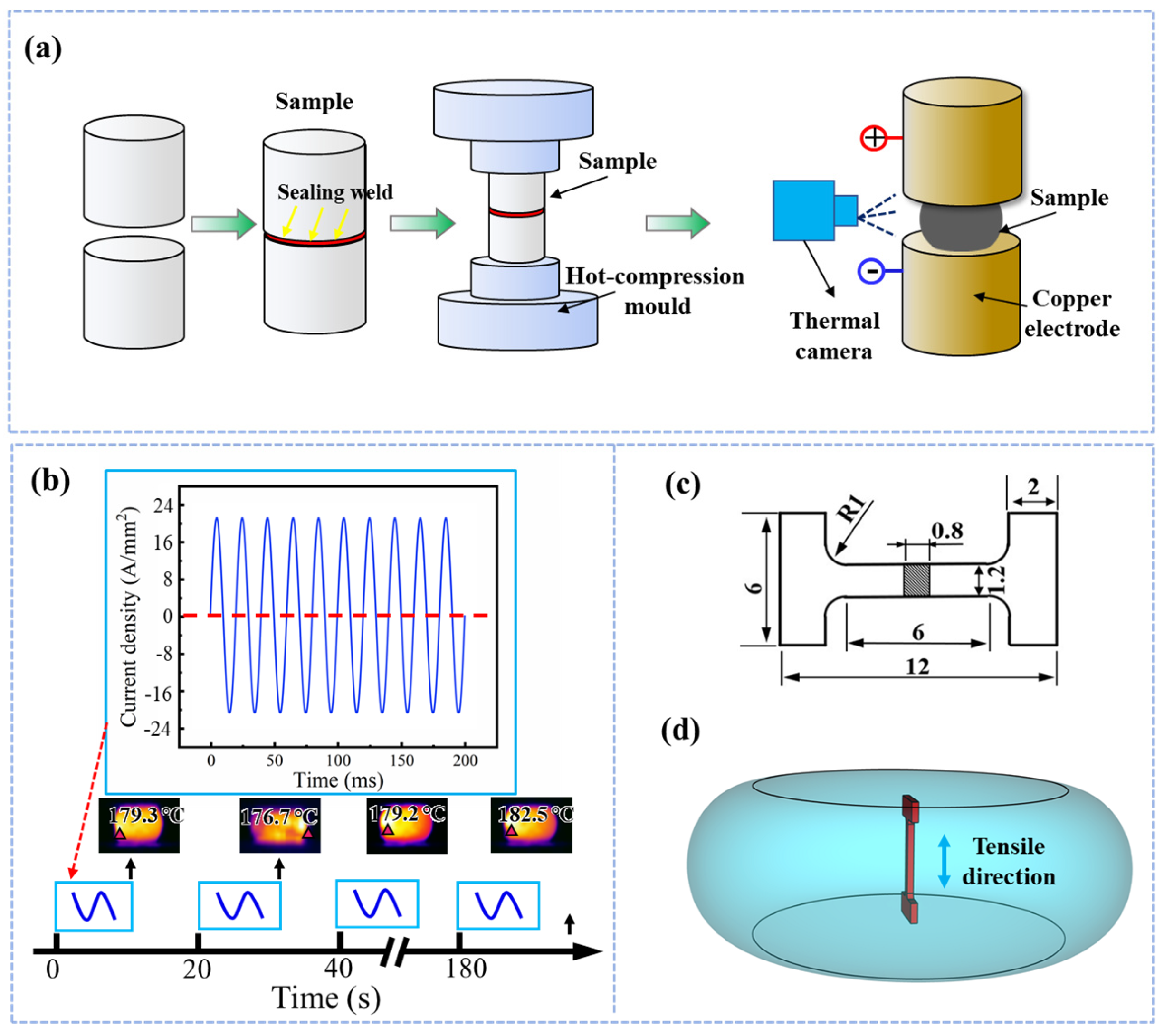
2.1. Materials Processing

The as-received sample was an austenitic stainless steel bar with a diameter of 80 mm. The chemical composition of the experimental steel was measured using the inductive coupled plasma atom emission spectrum (ICP-AES, PerkinElmer 8300, Markham, ON, Canada), as listed in Table 1. The initial optic microstructure of the experimental steel is shown in Figure 1, which indicates the full austenite microstructure in the matrix.
Figure 2a illustrates the conventional hot-deformation pre-bonding process of austenitic stainless steel. The cylindrical specimens with dimensions of Ø 20 mm × 15 mm were first polished, and then sealed by vacuum-gas-shielded welding with a welding penetration of 1.5 mm. After the sealing, the pre-bonded samples were heated to 1100 °C and then directly compressed with a total height reduction of 60% using a thermomechanical simulate tester (Gleeble 1500, DSI Corporation, Washington, WA, USA). After the hot-deformation bonding process, the cross-sectional microstructure of the samples was observed by optical microscopy (OM, Carl Zeiss, Axio Scope, Jena, Germany). It can be seen from Figure 3 that, despite the application of vacuum sealing, there are still incomplete healing interfaces after the hot-deformation bonding process. This will seriously affect the interface strength of the material. In this context, a novel technical method using electromagnetic shocking conducted on the interface was proposed and tested in this work.
The hot-deformation pre-bonded samples were subsequently subjected to the fast EST process using a self-made EST generator. The peak current density was set as 62.5 A/mm2 with a frequency of 50 HZ. The waveform of the electromagnetic pulse was set as a sine wave. The direction of electromagnetic shock loading was perpendicular to the pre-bonded interface. During the EST, the temperature variations in the specimens caused by joule heating were monitored and the temperature–time curves were obtained by means of an infrared thermal imager (Fotric 226, Shanghai, China) with an absolute precision of 0.1 °C. It should be noted that the maximum temperature rise only reached 182.5 °C due to the rapid cooling within a 20 s time-gap (Figure 2b).

2.2. Characterization Methods

In order to detect the interface difference caused by the EST process, a rectangular area was also selected in the middle of the sample and marked with hardness pits for the in situ observation of the interface. The morphology of the interface was characterized using a field emission scanning electron microscope (FESEM, Zeiss Auriga, Boston, Massachusetts, MS, USA). The element distribution around the bonded interface was detected by element mapping using energy-dispersive spectroscopy (EDS, X-Max50, Oxford Instruments, Abingdon, Great Britain). In addition, the texture and micro strain distribution were observed by using a field emission scanning electron microscope (EDAX-TSL, EDAX, Pleasanton, CA, USA) equipped for electron backscatter diffraction (EBSD). The specimens used for EBSD analysis were prepared via mechanical grinding and then subjected to colloidal silica polishing.
The micro size tensile test was carried out using an AG-IC universal material testing machine (Sansi, Shanghai, China) at a strain rate of 10−3 s−1. The dimensions of the tensile samples cut from the compressed steel are shown in Figure 2c. To analyze the bonding strength variety before and after EST, the tensile direction was perpendicular to the hot-deformation pre-bonded interface (Figure 2d). After the tensile fracture, the fracture location of the samples was confirmed at the bonded interface, and then the fracture morphology was further observed and analyzed using a SEM.

3. Results and Discussion

3.1. Characterization of the Bonded Interface

Figure 4a,b shows the optical image of the hot-deformation bonded interface before and after EST, respectively. Obviously, the width of the interface becomes narrower after EST, and some interfaces can no longer be found under the optical microscope (as illustrated in the red dashed box). In addition, the local unhealed interface was observed in detail (Figure 4c,d), where it can be seen that the size of voids at the interface decreased significantly after EST. The interface distance of the area marked with a black dotted frame was significantly shortened, indicating that the opposite displacement occurred on both sides of the interface. The elemental analysis of the interface was carried out as illustrated in Figure 4e,f. Before EST, the interface at point A was enriched with O and Mn elements, demonstrating that the oxide of Mn was formed during the hot-deformation bonding process due to the fact that the oxygen cannot be completely removed during sealing welding. However, the elements O and Mn both distinctly decreased in the same area after EST, especially the element Mn, which decreased from 25.41 wt.% to 4.87 wt.%. Under EST, the oxide of Mn with higher electric resistance should be decomposed and then diffused in the direction away from the interface, to reduce the overall resistance. As a result, the decrease in elements O and Mn in the interface would enhance the bonding strength of the interface. The decomposed mechanism of Mn oxide will be discussed later.
The above results show that EST can promote interfacial void healing and oxide decomposition. It is reported that the detour effect occurs when the current passes through the specimen, which will result in a higher temperature locally at the bonded interface [21,22]. The difference between the high local temperature and the substrate temperature will produce huge compressive stress. The compressive stress will promote the opposite movement of the interfaces on both sides, so as to eliminate interface voids and shorten the interface distance. The decomposition of oxide at the interface also exerts an important influence on interfacial homogenization healing. The change in the free energy ΔG of the system caused by the difference in conductivity between the oxide and matrix leads to the dissolution of oxide at the interface, which can be expressed as [23,24]:
Δ G = Δ G c h e m + Δ G i n t e r + Δ G s t r a i n + Δ G E S T
where Δ G c h e m is the chemical free energy, Δ G i n t e r is the interfacial free energy between the oxide and matrix, Δ G s t r a i n is the strain–stress energy, and Δ G E S T is the change in free energy due to the electric current passing the oxides. Δ G i n t e r and Δ G s t r a i n are barriers to prevent oxide decomposition, while Δ G c h e m and Δ G E S T provide a positive effect on oxide decomposition. Due to the ellipsoidal-like shape of oxides, Δ G E S T can be briefly described as [25,26,27,28]:
Δ G E S T = π μ k j 2 Δ a a
where μ is the shear modulus, k is the geometric factor that relates to the oxide shape, j is current density, a is the long dimension of the oxide, and Δ a is the change in the oxide length. The Δ G E S T decreases with the increase in the current density when Δ a < 0 , i.e., during the process of oxide decomposition. Therefore, the thermodynamic barrier of oxide decreases under the application of EST and thus promotes the dissolution of oxide at the interface. In addition, as reported by Conrad’s work, the EST process can enhance diffusivity by a factor of over 1000 [29]. Thus, the higher diffusivity of atoms induced by EST should also be responsible for the decomposition and diffusion of Mn oxides.
Figure 5 illustrates the in situ EBSD characterization of the interface. The Inverse Pole Figure (IPF) mappings show that there are few visible changes in the grain size around the interface. Considering that the temperature rise is lower than 180 °C, significant grain growth or phase transformation is unlikely to occur under EST [28]. However, it can be seen from the Kernel Average Misorientation mappings (KAM) that the micro stress was decreased after EST, especially at the interface. Before EST, the high stress at the interface should be caused by the coordinated deformation at both ends of the interface during bonding. The stress relief could be attributed to the dislocation movement induced by EST, which should also contribute to the interface healing process.
The texture on both sides of the interface is also an important factor affecting the interfacial bonding performance. The bonding strength at the interface will be significantly weakened considering the obvious differences in texture between the two ends of the interface [30]. As shown in Figure 5c, there are differences in texture between the upper and lower ends of the interface. These differences are due to the interface breaking the orientation connection on both sides, which will be detrimental to the tensile properties.
After EST, although the texture types of the upper and lower sides of the interface have not changed significantly, the difference in texture intensity between the two sides has decreased. This is a great contribution to the orientation connection of the bonded interface. It has been reported that the texture evolution could exert a distinct effect on the electrical conductivity of metals [31]. The greater the texture differences in different regions of the material, the lower the conductivity of the metal. When the electric current passes through the metal, the directional texture will be formed along the direction of total resistance reduction [32]. Therefore, it can be expected that the texture on both sides of the interface is regulated by the EST in the way of electrical resistance reduction. As a result, the texture intensity on both sides of the interface is closer, while there is no obvious change in the texture type.
On the other hand, according to the EST-induced interface instability theory proposed by Klinger et al. [33], the diffusive flux along the hot-deformation pre-bonded interface is affected by the following: (1) chemical potential change caused by EST (φ); (2) associated internal tensile or compressive stress due to the accumulated or depleted interface (σ); and (3) curvature of the interface (k). The above three factors can be summed up in the following formula [34]:
J v = L v ± γ i k + q v i φ + i σ
where γ refers to the interface tension, L v is the mobility, and q v is the volume charge of the v-th component. During the EST, the bonded interface is not a smooth plane and the two sides of the interface have different atomic mobility levels and charges due to different orientations, which cause a diffusion flux gradient that promotes the change in texture orientations. This could also be the reason why the texture characteristics of the upper and lower parts of the interface tend to be consistent.

3.2. Bonding Strength Analysis

In order to verify an interfacial healing effect, a tensile test perpendicular to the interface was carried out. Figure 6a shows the tensile stress–strain curves for the specimens without and with EST. The fracture elongation increases without losing tensile strength, demonstrating that the tensile performance has been increased by promoted interface pre-bonding under EST. Furthermore, the tensile fractures are shown in Figure 6b,c, where it can be seen that the shear band increases from 15 μm to 100 μm. The increase in the width of the shear band indicates the higher resistance to fracture. Figure 6(b1,c1) presents the high-magnification morphology of the tensile fracture of the specimens without and with EST, respectively. There are some smooth oxides, unhealed voids, and a few dimples on the fracture surface for the untreated specimen, while the fracture surface of the sample after EST has larger dimples with a more uniform distribution. The composition of the smooth oxide at the fracture of the untreated sample was further analyzed. As shown in Figure 6d, the region A of the untreated specimen is rich in O and Mn elements, which is highly consistent with the composition analysis results in Figure 6. This also proves that the high brittleness of residual oxides is an important reason for the brittle fracture of the specimens without EST.
In addition, Figure 4f shows that oxides were decomposed under EST so that almost no oxide was found at the fracture after EST [Figure 6(c1)]. Based on the abovementioned results, it can be summarized that the unhealed voids and oxides that are detrimental to the tensile properties have been significantly reduced after EST. The healing of voids and decomposition of oxides at the hot-deformation pre-bonded interface will make the interface connection tighter, which thus leads to an increase in the ductility of the bonded specimen. Furthermore, the decrease in interfacial stress (as shown in Figure 5) may also be a main reason for the later occurrence of tensile fracture. As a consequence, the fracture model gradually changes from brittle fracture to ductile fracture after EST.

4. Conclusions

In summary, a novel EST processing method has been proposed to solve the traditional interface connection issues in this work. It is found that the EST can efficiently optimize the hot-deformation pre-bonded interface and restore the tensile properties within several seconds. The main conclusion can be drawn as follows:
(1)
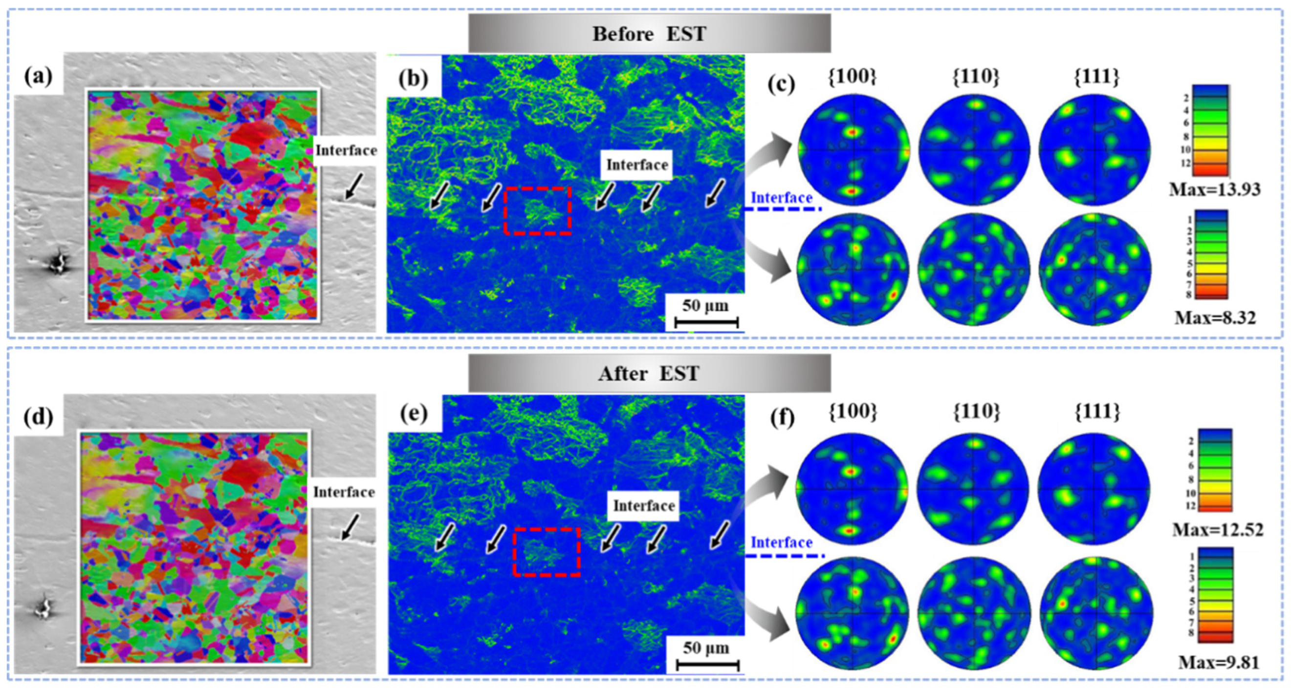
The microstructure observation indicates that the hot-deformation bonded in interface has been significantly healed, accompanied by the recovery of voids after EST. In addition, the Mn oxide at the interface is decomposed or diffused due to the accelerated thermodynamic dissolution of oxide under EST. The optimization of the interface connection is mainly reflected in the fact that EST can act on the interface locally, leading to the healing of voids at the interface accompanied by a reduction in the residual stress and the decomposition of oxide.
(2)
The texture characteristics of the upper and lower parts of the interface tend to be consistent after the EST, indicating that EST plays an important role in adjusting the texture difference at both ends of the interface. This should be closely associated with the movement of atoms promoted by EST, in order to optimize the orientation connection at both sides of the hot-deformation bonded interface.
(3)
The mechanical property tests show that the fracture elongation increases without tensile strength loss, demonstrating that the tensile performance has been increased by the interface pre-bonding promoted under EST. The improvement of the tensile properties should be attributed to the void healing, oxide decomposition and texture adjustment at the interface. Conclusively, the results obtained in this work suggest a novel and bright idea for eliminating the smelting defects in the manufacturing of large-scale billets.

Author Contributions

M.W.: Conceptualization, Writing-original draft, Investigation, and Visualization; J.C.: Investigation, Methodology, Data curation, and Writing—review and editing; J.D.: Investigation and Visualization; F.W.: Supervision, Funding acquisition, and Writing—review and editing; Q.S.: Funding acquisition, and Writing—review and editing. All authors have read and agreed to the published version of the manuscript.

Funding

This work was supported by the National Key R&D Program of China (No. 2018YFA0702900), National Natural Science Foundation of China (No. 52305414, 51805391), 111 Project (B17034), and Innovative Research Team Development Program of Ministry of Education of China (No. IRT_17R83).

Data Availability Statement

The data used to support the findings of this study are available from the corresponding author upon request.

Acknowledgments

The authors are grateful for the funding.

Conflicts of Interest

The authors declare that they have no known competing financial interest or personal relationships that could have appeared to influence the work reported in this paper.

References

  1. Sun, M.; Xu, B.; Xie, B.; Li, D.; Li, Y. Leading manufacture of the large-scale weldless stainless steel forging ring: Innovative approach by the multilayer hot-compression bonding technology. J. Mater. Sci. Technol. 2021, 71, 84–86. [Google Scholar] [CrossRef]
  2. Flemings, M.C. Our Understanding of Macrosegregation: Past and Present. ISIJ Int. 2000, 40, 833–841. [Google Scholar] [CrossRef]
  3. Li, D.; Chen, X.-Q.; Fu, P.; Ma, X.; Liu, H.; Chen, Y.; Cao, Y.; Luan, Y.; Li, Y. Inclusion flotation-driven channel segregation in solidifying steels. Nat. Commun. 2014, 5, 5572. [Google Scholar] [CrossRef] [PubMed]
  4. Sridharan, N.; Gussev, M.; Seibert, R.; Parish, C.; Norfolk, M.; Terrani, K.; Babu, S.S. Rationalization of anisotropic mechanical properties of Al-6061 fabricated using ultrasonic additive manufacturing. Acta Mater. 2016, 117, 228–237. [Google Scholar] [CrossRef]
  5. Malik, N.; Carvalho, P.A.; Poppe, E.; Finstad, T.G. Interfacial characterization of Al-Al thermocompression bonds. J. Appl. Phys. 2016, 119, 205303. [Google Scholar] [CrossRef]
  6. Xie, B.; Sun, M.; Xu, B.; Wang, C.; Zhang, J.; Zhao, L.; Li, D.; Li, Y. Evolution of interfacial characteristics and mechanical properties for 316LN stainless steel joints manufactured by hot-compression bonding. J. Mater. Process. Tech. 2020, 283, 116733. [Google Scholar] [CrossRef]
  7. Xie, B.; Sun, M.; Xu, B.; Wang, C.; Li, D.; Li, Y. Dissolution and evolution of interfacial oxides improving the mechanical properties of solid state bonding joints. Mater. Design 2018, 157, 437–446. [Google Scholar] [CrossRef]
  8. Zhang, J.Y.; Sun, M.Y.; Xu, B.; Hu, X.; Liu, S.; Xie, B.J.; Li, D.Z. Evolution of the interfacial microstructure during the plastic deformation bonding of copper. Mat. Sci. Eng. A 2019, 746, 1–10. [Google Scholar] [CrossRef]
  9. Liang, C.L.; Lin, K.L. The microstructure and property variations of metals induced by electric current treatment: A review. Mater. Charact. 2018, 145, 545–555. [Google Scholar] [CrossRef]
  10. Qian, D.; Wang, R.; Dong, Z.; Wang, F. Microstructure Evolution and Wear Resistance Improvement of Ultrasonic Peened M50 Steel via Electromagnetic Shocking. Steel Res. Int. 2023, 2300067. [Google Scholar] [CrossRef]
  11. Yue, X.; Hu, S.; Yin, F.; Hua, L. Athermally induced MC carbide decomposition in gradient M50 bearing steels during electric pulse treatments. J. Mater. Sci. 2023, 58, 15251–15263. [Google Scholar] [CrossRef]
  12. Zhang, D.; Shi, D.; Wang, F.; Qian, D.; Zhou, Y.; Fu, J.; Chen, M.; Qiu, D.; Jiang, S. Electromagnetic Shocking Induced Fatigue Improvement via Tailoring the α-Grain Boundary in Metastable β Titanium Alloy Bolts. J. Alloys Compd. 2023, 966, 171536. [Google Scholar] [CrossRef]
  13. Yang, C.L.; Yang, H.J.; Zhang, Z.J.; Zhang, Z.F. Recovery of tensile properties of twinning-induced plasticity steel via electropulsing induced void healing. Scr. Mater. 2018, 147, 88–92. [Google Scholar] [CrossRef]
  14. Xie, L.; Guo, H.; Song, Y.; Hua, L.; Wang, L.; Zhang, L.-C. Novel Approach of Electroshock Treatment for Defect Repair in Near-β Titanium Alloy Manufactured via Directed Energy Deposition. Metall. Mater. Trans. A 2021, 52, 457–461. [Google Scholar] [CrossRef]
  15. Wang, F.; Qian, D.; Hua, L.; Mao, H.; Xie, L. Voids healing and carbide refinement of cold rolled M50 bearing steel by electropulsing treatment. Sci. Rep. 2019, 9, 11315. [Google Scholar] [CrossRef] [PubMed]
  16. Yu, T.; Deng, D.W.; Wang, G.; Zhang, H.C. Crack healing in SUS304 stainless steel by electropulsing treatment. J. Clean. Prod. 2016, 113, 989–994. [Google Scholar] [CrossRef]
  17. Hosoi, A.; Nagahama, T.; Ju, Y. Fatigue crack healing by a controlled high density electric current field. Mater. Sci. Eng. A 2012, 533, 38–42. [Google Scholar] [CrossRef]
  18. Liu, X.; Yang, Y.; Chen, H.; Li, Y.; Xu, S.; Zhang, R. Mesoscopic defect healing and fatigue lifetime improvement of 6061-T6 aluminum alloy by electropulsing treatment. Eng. Fail. Anal. 2023, 146, 107111. [Google Scholar] [CrossRef]
  19. Rahnama, A.; Qin, R. Room temperature texturing of austenite/ferrite steel by electropulsing. Sci. Rep. 2017, 7, 42732. [Google Scholar] [CrossRef]
  20. Guo, J.D.; Wang, X.L.; Dai, W.B. Microstructure evolution in metals induced by high density electric current pulses. Mater. Sci. Tech. 2015, 31, 1545–1554. [Google Scholar] [CrossRef]
  21. Hua, L.; Liu, Y.; Qian, D.; Xie, L.; Wang, F.; Wu, M. Mechanism of void healing in cold rolled aeroengine M50 bearing steel under electroshocking treatment: A combined experimental and simulation study. Mater. Charact. 2022, 185, 111736. [Google Scholar] [CrossRef]
  22. Liu, C.; Yin, F.; Xie, L.; Qian, D.; Song, Y.; Wu, W.; Wang, L.; Zhang, L.-C.; Hua, L. Evolution of grain boundary and texture in TC11 titanium alloy under electroshock treatment. J. Alloys Compd. 2022, 904, 163969. [Google Scholar] [CrossRef]
  23. Qin, R.S.; Samuel, E.I.; Bhowmik, A. Electropulse-induced cementite nanoparticle formation in deformed pearlitic steels. J. Mater. Sci. 2011, 46, 2838–2842. [Google Scholar] [CrossRef]
  24. Qin, R.S.; Rahnama, A.; Lu, W.J.; Zhang, X.F.; Elliott-Bowman, B. Electropulsed steels. Mater. Sci. Tech. 2014, 30, 1040–1044. [Google Scholar] [CrossRef]
  25. Su, X.; Wang, S.; OuYang, X.; Song, P.; Xu, G.; Jiang, D. Physical and mechanical properties of 7075 sheets produced by EP electro- and electromagnetic cast rolling. Mat. Sci. Eng. A 2014, 607, 10–16. [Google Scholar] [CrossRef]
  26. Zhang, X.; Qin, R. Electric current-driven migration of electrically neutral particles in liquids. Appl. Phys. Lett. 2014, 104, 114106. [Google Scholar] [CrossRef]
  27. Wang, X.L.; Guo, J.D.; Wang, Y.M.; Wu, X.Y.; Wang, B.Q. Segregation of lead in Cu–Zn alloy under electric current pulses. Appl. Phys. Lett. 2006, 89, 061910. [Google Scholar] [CrossRef]
  28. Qin, R.S.; Su, S.X. Thermodynamics of crack healing under electropulsing. J. Mater. Res. 2002, 17, 2048–2052. [Google Scholar] [CrossRef]
  29. Hans, C. Influence of an electric or magnetic field on the liquid–solid transformation in materials and on the microstructure of the solid. Mater. Sci. Eng A. 2020, 287, 205–212. [Google Scholar]
  30. Song, X.D.; Wang, F.; Qian, D.S.; Hua, L. Tailoring the residual stress and mechanical properties by electroshocking treatment in cold rolled M50 steel. Mater. Sci. Eng. A 2020, 780, 139171. [Google Scholar] [CrossRef]
  31. Wu, C.; Zhao, Y.; Xu, X.; Yin, P.; Qiu, X. Electropulse-induced laminated structures in a ferritic-pearlitic 35CrMo steel. Scr. Mater. 2019, 165, 6–9. [Google Scholar] [CrossRef]
  32. Dolinsky, Y.; Elperin, T. Thermodynamics of phase transitions in current-carrying conductors. Phys. Rev. B 1993, 47, 14778–14785. [Google Scholar] [CrossRef] [PubMed]
  33. Dolinsky, Y.; Elperin, T. Thermodynamics of nucleation in current-carrying conductors. Phys. Rev. B 1994, 50, 52–58. [Google Scholar] [CrossRef] [PubMed]
  34. Klinger, L.; Levin, L.; Srolovitz, D.J. Interface Diffusion under an Electric Field. Interface Evolution. MSF 1996, 207–209, 109–112. [Google Scholar] [CrossRef]
Figure 1. Initial microstructure of the received steel.
Metals 13 02004 g001
Figure 2. (a) The conventional hot-deformation pre-bonding process and subsequent EST process. (b) Schedule of EST process and the record of maximum temperature for each pulse. (c) Dimensions of micro-tensile specimen for bonding strength tests. (d) Sampling method of the tensile tests.
Metals 13 02004 g002
Figure 3. The cross-sectional microstructure of the samples subjected to a conventional hot-deformation pre-bonding process.
Metals 13 02004 g003
Figure 4. In situ observation of the optical images and SEM images of the hot-deformation pre-bonded interface (a,c) before EST and (b,d) after EST. (e,f) The elemental analysis results of point A and B marked in (c,d).
Metals 13 02004 g004
Figure 5. In situ EBSD characterization of the interface without EST and with EST: (a,d) IPF, (b,e) KAM, and (c,f) texture analysis of both ends of the interface.
Metals 13 02004 g005
Figure 6. (a) Tensile stress–strain curves; (b,b1) fracture morphology of the specimens without EST; (c,c1) fracture morphology of the specimens with EST; (d) elemental analysis for points A and B at the tensile fracture.
Metals 13 02004 g006
Table 1. Chemical composition of the experimental steel (wt.%).
CCrNiMnSiSFe
0.02318.5328.3231.1800.5100.002Bal.
Disclaimer/Publisher’s Note: The statements, opinions and data contained in all publications are solely those of the individual author(s) and contributor(s) and not of MDPI and/or the editor(s). MDPI and/or the editor(s) disclaim responsibility for any injury to people or property resulting from any ideas, methods, instructions or products referred to in the content.

