Article

Structure and Wear Resistance of Composite TiC-NiMo Coating Produced by L-DED on Ti-6Al-4V Substrate

Institute of Machinery, Materials and Transport, Peter the Great St. Petersburg Polytechnic University, 29, Polytechnicheskaya Street, 195251 Saint Petersburg, Russia
*
Author to whom correspondence should be addressed.
Metals 2023, 13(12), 1925; https://doi.org/10.3390/met13121925
Submission received: 16 October 2023 / Revised: 13 November 2023 / Accepted: 22 November 2023 / Published: 23 November 2023

Abstract

:
Fabrication of W- and Co-free wear-resistant cermets is a vital task in modern machinery due to the toxicity of Co-based products and poor availability of Co and W containing raw materials. In this paper, a TiC-NiMo coating produced by laser-directed energy deposition (L-DED) on a Ti-6Al-4V substrate was demonstrated. Mechanical alloying of TiC, Ni and Mo powders followed by spray-drying was proposed to fabricate a feedstock spherical composite powder suitable for an L-DED machine. It was shown that this method is more applicable in the case of a TiC-containing composition than gas atomization and plasma spheroidization methods. The size of the resulting particles was in the range of 10–100 μm while the size of the 70 vol.% was in the range of 45–75 μm. L-DED provided a good adhesion of the coating, though the presence of pores and transverse cracks was also observed. The coating’s hardness was up to 1500 HV, which is not inferior to the hardness of known TiC-based cermets and is promising for obtaining a good wear resistance of the coating. It was shown that it depended on the thickness due to the mixing zone influence. The coating structure contained TiC- and Mo-based precipitates and a Ni-based binder. The weight loss of the coating samples after an abrasive wear test with 4000 revolutions of a testing wheel was 0.0464 g and that can be considered insignificant. The wear did not lead to the appearance of new defects and cleavage of the coating. Further optimization of the component ratio and L-DED parameters could help to improve the performance of the coating and make this technology rather promising to improve the wear resistance of machinery parts working in high-wear environments.

1. Introduction

Parts operating at an increased wear must simultaneously have a high strength and good ductile properties, in particular, a sufficiently high impact strength. However, for conventional steels and alloys, it is quite difficult to provide a suitable complex of mechanical properties. One of the successful technical solutions for wear-resistant parts is the use of composite hard alloys based on a Co matrix with embedded particles of WC and cermets based on the embedded particles of TiC or Ti(C,N) [1,2]. They are widely used as materials for cutting tools, turbine parts, aircraft engines, friction elements and parts operating in aggressive environments and at elevated temperatures.
At the moment, most composite alloys are based on the WC-Co system. However, according to the European REACH program, products based on these components are considered toxic and carcinogenic, both in powder and compact form. There is also a problem with the availability of Co and W raw materials. The shortage and the toxicity of such alloys provided the development of Co- and W-free hard alloys. Various compositions based on titanium carbides, nitrides and borides are being studied as a reinforcing phase [3,4] in a variety of matrices, ranging from steels to high-entropy alloys [5,6,7,8]. Cermets based on titanium carbides and carbonitrides with a metal binder of Ni, Fe and Mo are a promising replacement for hard alloys based on tungsten carbides [1] due to their unique properties despite their somewhat inferior hardness and wear resistance [3].
TiC has a high melting point, low density, good thermal and electrical conductivity, high hardness, high strength and corrosion resistance that allows for the use of TiC-based cermets in cutting tools, wear-resistant coatings and parts operating in aggressive environments [9,10]. The introduction of ceramic TiC particles into a more ductile metal matrix allows for the implementation of an additional mechanism of dispersion strengthening, which is often used to increase the strength of Ni-based alloys such as Inconels [11,12,13]. Since wear environments imply high local temperatures, it is reasonable to add high melting point elements such as Mo to a Ni-based matrix to increase its heat resistance.
The main methods for producing composite hard alloys are powder metallurgy (PM) methods including mechanical alloying, sintering, high-temperature synthesis and so on [5,14,15]. Currently, a large number of studies are dedicated to using additive technologies (ATs) for the fabrication of products and coatings from cermets [8,16,17]. Additive technologies are based on the design of a three-dimensional CAD model and layer-by-layer manufacturing of the product, which makes it possible to obtain more complex geometries and a higher strength compared to those of traditionally manufactured items. ATs also help to significantly reduce post-processing operations and material consumption [18,19,20].
Additive technologies, which use a laser beam as an energy source, also allow for achieving a fine-grained structure of metal alloys [18,19,20]. The most widely used ATs for manufacturing cermet-based products are laser powder bed fusion (L-PBF) [8,15,16] and laser-directed energy deposition (L-DED) [21,22,23]. L-PBF technology provides a higher precision and better quality of a product surface than L-DED technology, but the speed of the process is lower [24]. In addition, L-DED technology is more promising for the fabrication of wear-resistant coatings and subsequent repair of the products. Manufacturing of the cermets using AT processes can be challenging due to the brittleness of the ceramics. The fabrication of cermets using a laser beam causes rapid melting and cooling of the melt pool. It results in a complex profile of residual thermal stresses in the manufactured part [25,26], which can lead to the formation of defects such as cracks, delamination and porosity, and can also lead to the coagulation of strengthening particles due to the lower density of ceramics compared to a metal matrix [27,28]. The selection of printing and post-processing modes is an important aspect for the reduction in internal stresses and elimination of such defects.
It is also important to correctly combine coating and substrate compositions which significantly influence the adhesion of the coating and subsequent wear resistance. For the good performance of the coating, compositions with similar coefficients of thermal expansion are usually applied. L-DED technology has advantages over other methods due to the partial melting of the substrate; the powder is also melted and is partially mixed with the material of the substrate resulting in the formation of a strong bond between them.
This work aimed to study the technological steps of the additive manufacturing of a TiC-NiMo cermet including the production of a feedstock composite powder and the coating application on a Ti-6Al-4V substrate using the L-DED method and their influence on the structure and properties of the TiC-NiMo cermet coating.

2. Materials and Methods

2.1. Fabrication of Composite Powders

To produce a TiC-NiMo composite powder, commercial powders of TiC (D50 = 7 µm), Ni (D50 = 18 µm) and Mo (D50 = 25 µm) were used as feedstock materials. The morphology of these powders is presented in Figure 1. The components were mixed in the ratio of 79 wt.% TiC, 15 wt.% Ni and 6 wt.% Mo and the mixture was placed into a Fritsch Pulverisette 4 vario-planetary mill (Fritsch, Idar-Oberstein, Germany) with grinding balls made of a WC-based hard alloy. Then, mechanical alloying (MA) was carried out in Ar atmosphere according to the following modes: the ratio of the powder mixture mass to the grinding balls mass was 1:20, disk/bowl rotation speed was 200/−400 rpm, grinding time was 3 h.
After MA, spray-drying was carried out using an LPG-5 device (Changzhou Yibu Drying Equipment Co., Ltd., Changzhou, Jiangsu, China). The spray-drying process is as follows. The filtered heated air is uniformly supplied by a spiral downward flow into the drying chamber through an air distributor. A suspension of solvent binder and powder filler is sprayed into the drying chamber through a centrifugal disc grinder. Upon contact with hot air, small drops of the sprayed suspension disintegrate, dry out and form individual small particles falling to the bottom of the chamber. A 2% aqueous solution of polyvinyl alcohol (PVA) was used as a binder; the mass ratio of powder to binder was 1:1. The air temperature in the process of spray-drying was 95 °C. The rotation frequency of the grinding disk varied within the range of 15–50 Hz. The powder feed rate was 1.5 kg/h.

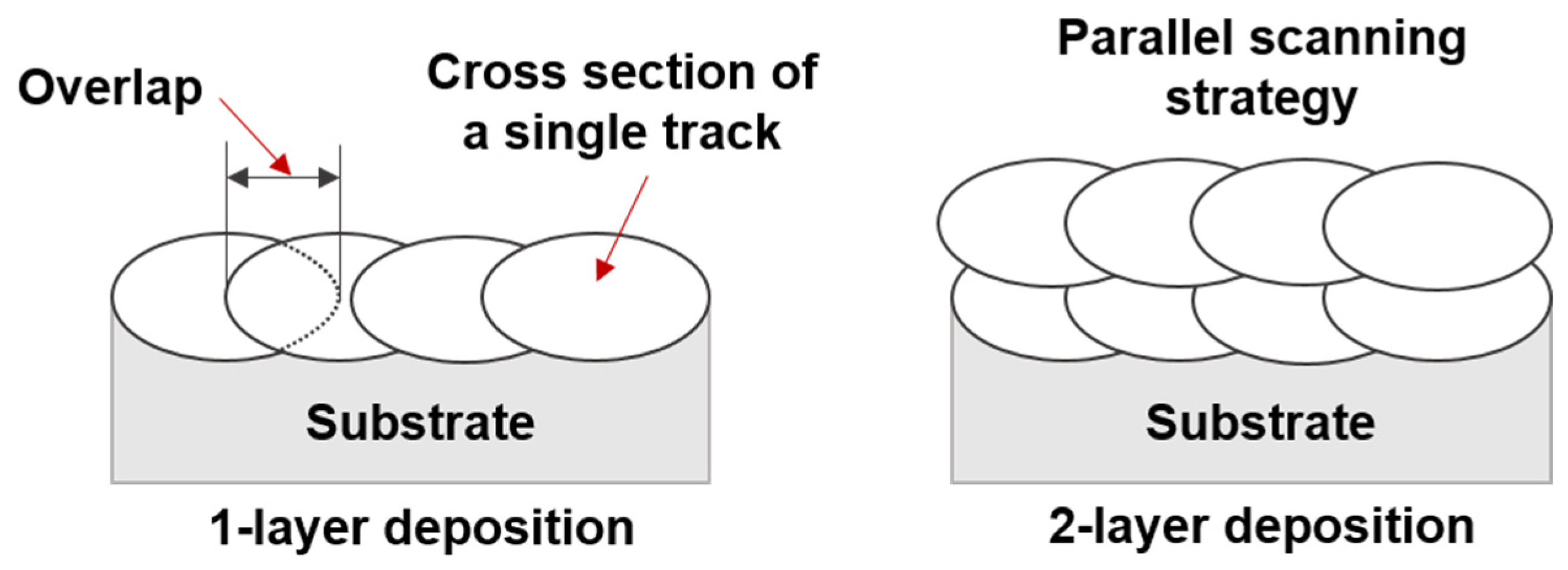
2.2. Coating Deposition by L-DED

The coating was produced by L-DED technology. It was carried out using a high-speed laser machine ZKZM (zKzM Laser Technology Co., Ltd., Xi’an, China). The main feature of this installation is the laser head. Inside it, the powder is coaxially fed, and the laser radiation generated by 4 modules placed on the head’s side is focused at one point, which is the zone of cladding. This method provides a high productivity of the machine combined with a minimization of the impact on the powder, in particular, a reduction in particle collision. To adjust the technology, the laser power and the velocity of the laser head movement were varied. Table 1 shows the mode that provided stability of powder deposition onto the Ti-6Al-4V substrate.
The laser beam width was 2.5 mm, protective argon gas flow rate was 20 L/min, carrier argon gas flow rate was 6 L/min, the layer height was 0.6 mm. The coating was applied in one and two layers. When depositing the second layer, a parallel scanning strategy was used and no shift of the tracks in relation to the previous layer was applied (Figure 2).

2.3. Characterization

The study of the morphology, structure and elemental composition was carried out using a Mira 3 Tescan scanning electron microscope equipped with detectors of secondary electrons (SEs) and back scattered electrons (BSEs), and EDX X-max 80 (Oxford instruments, Abingdon, Oxfordshire, England) device for energy-dispersive X-ray spectrometry (EDS).
Hardness was measured using a cross-section of the coatings on the substrate. The measurements were carried out according to the Vickers method described in ISO 6507-1 [29] using a Buehler Micromet 5103 (Buehler, Lake Bluff, IL, USA) microhardness tester. The load during the measurements was 5 N, the holding time was 10 s. For each state, at least 10 points were tested.
Particle size distribution was measured by laser diffractometer Fritsch Analysette 22 (Fritsch, Idar-Oberstein, Germany) using the wet method with ultrasound treatment. In this method, D50 is the maximum size of 50% of particles in the powder analyzed.
Wear tests were carried out using a G65 homemade testing machine according to ASTM G65 [30]. The test methodology consisted of abrading the surface of the test sample with dry abrasive quartz SiO2 particles with a size of 0.4–0.8 mm. The tests were carried out according to procedure B, including a load of 130 N applied to the sample and 2000 wheel revolutions. The wheel diameter was 228 mm. Upon completion of the tests, the weight loss of the samples was determined. Weighing was carried out using analytical balances with an accuracy of 0.0001 g. Figure 3 shows the diagram of the testing setup.
The study of the surface before and after wear tests was carried out using a Meiji Techno (Meiji Techno, Campbell, CA, USA) scanning microscope at the magnification of ×1.5.

3. Results and Discussion

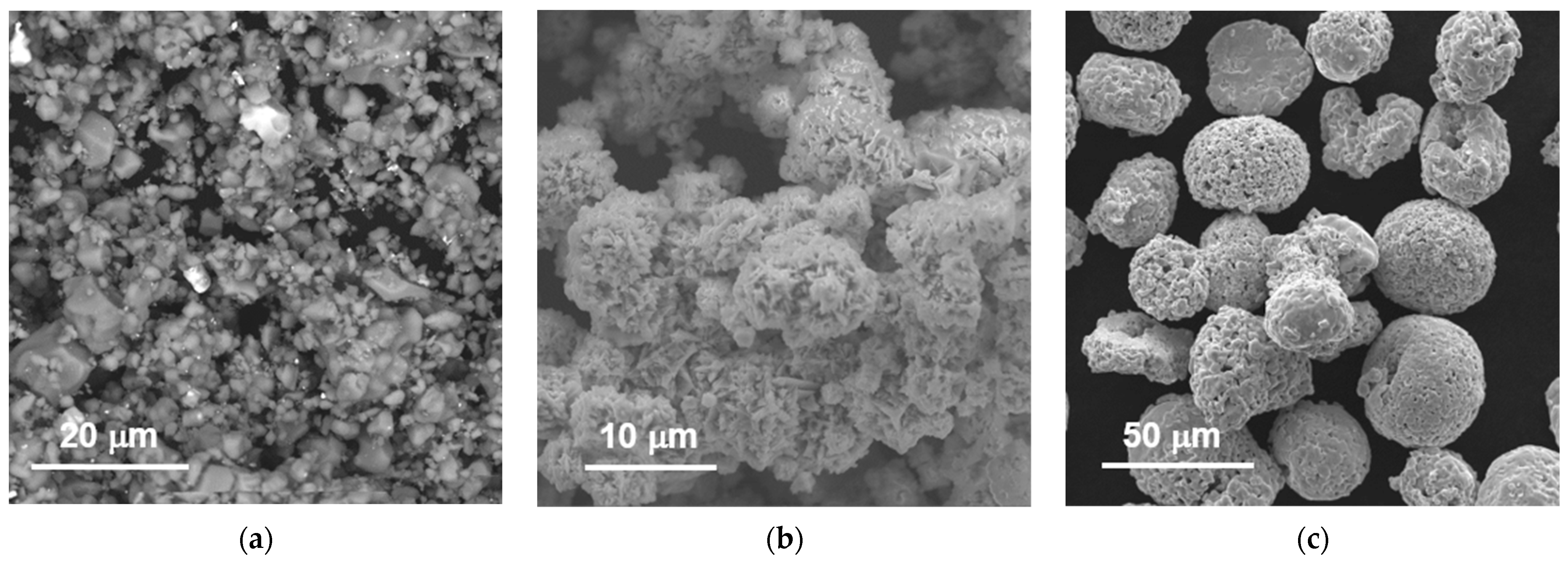
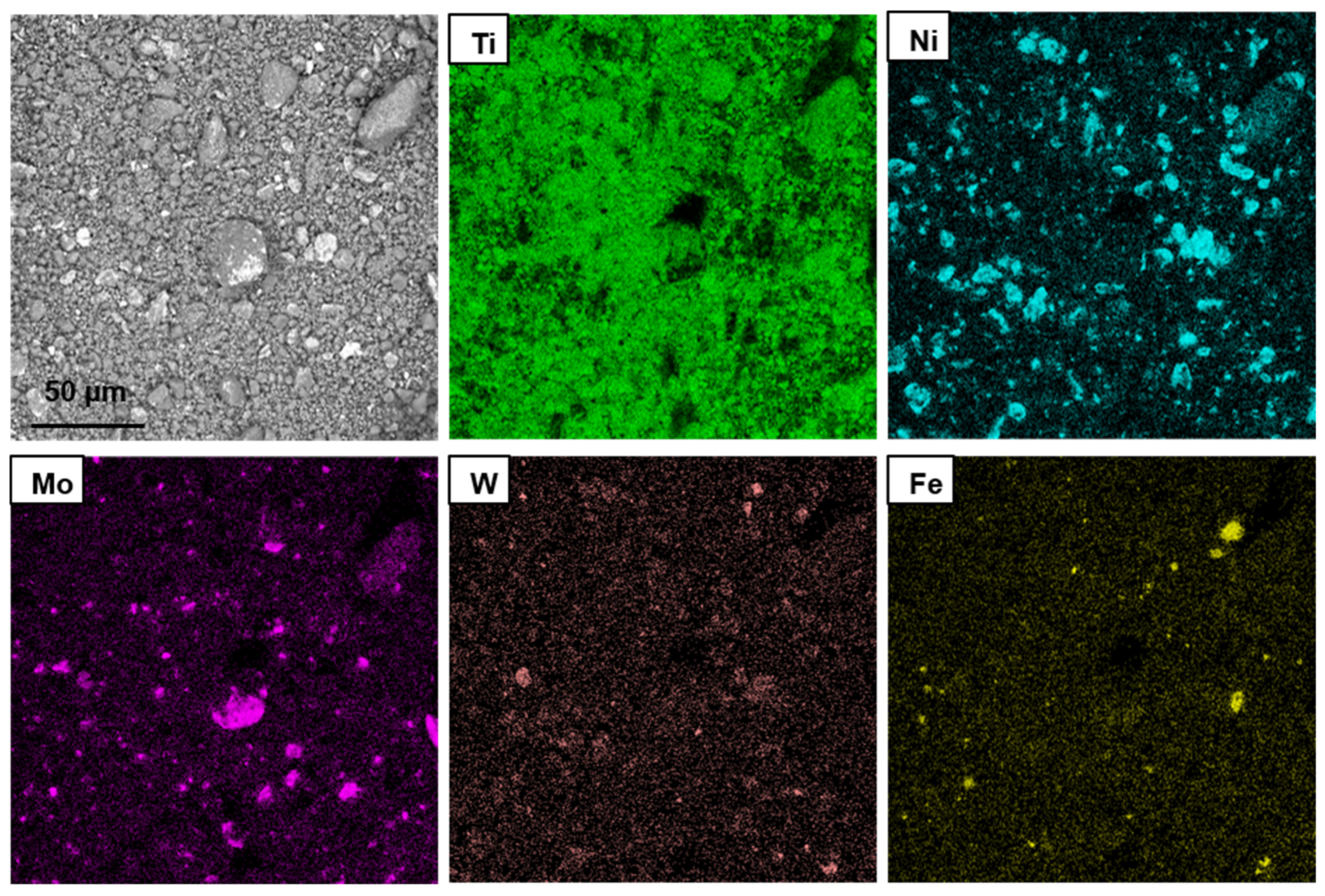
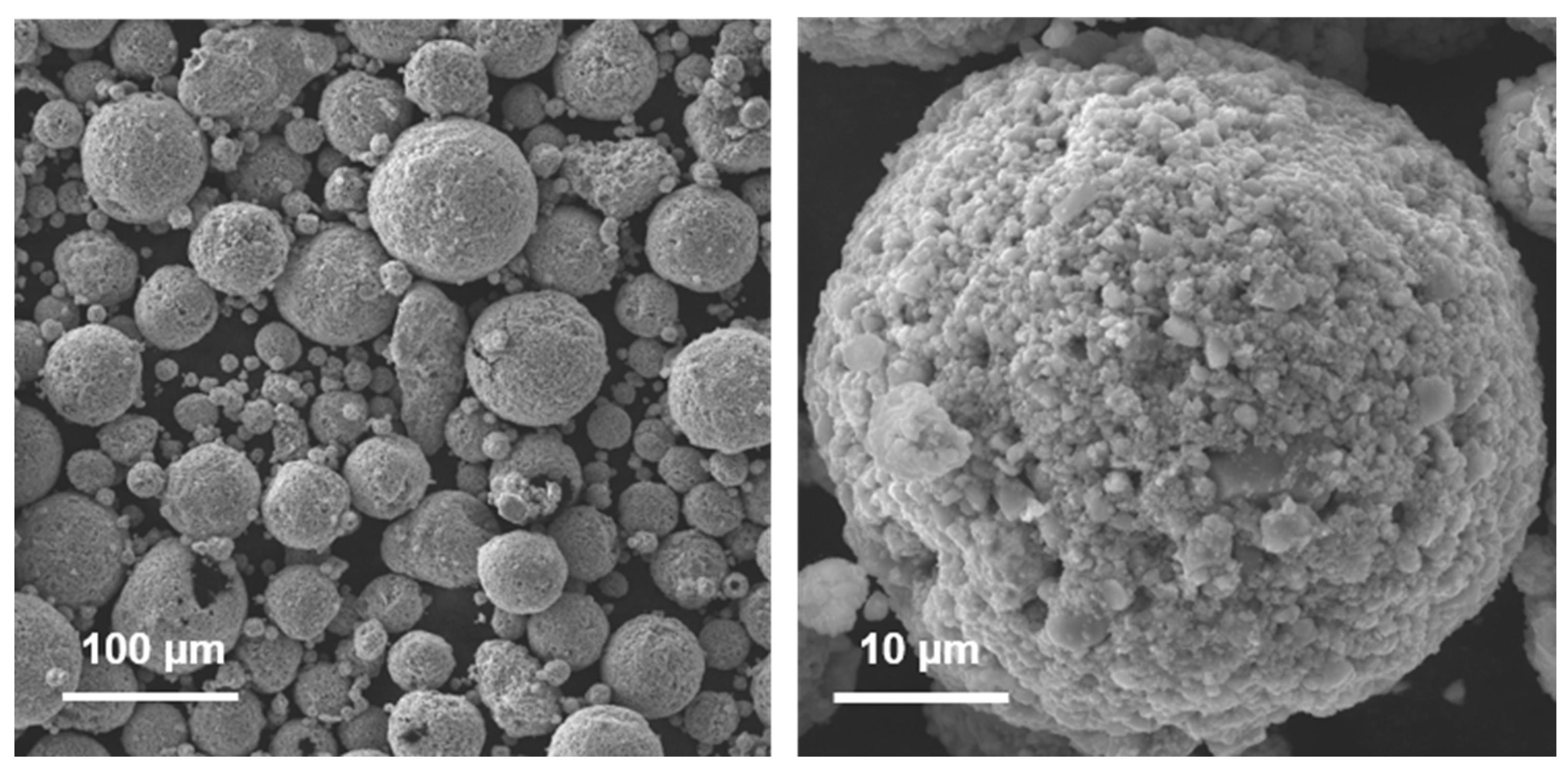
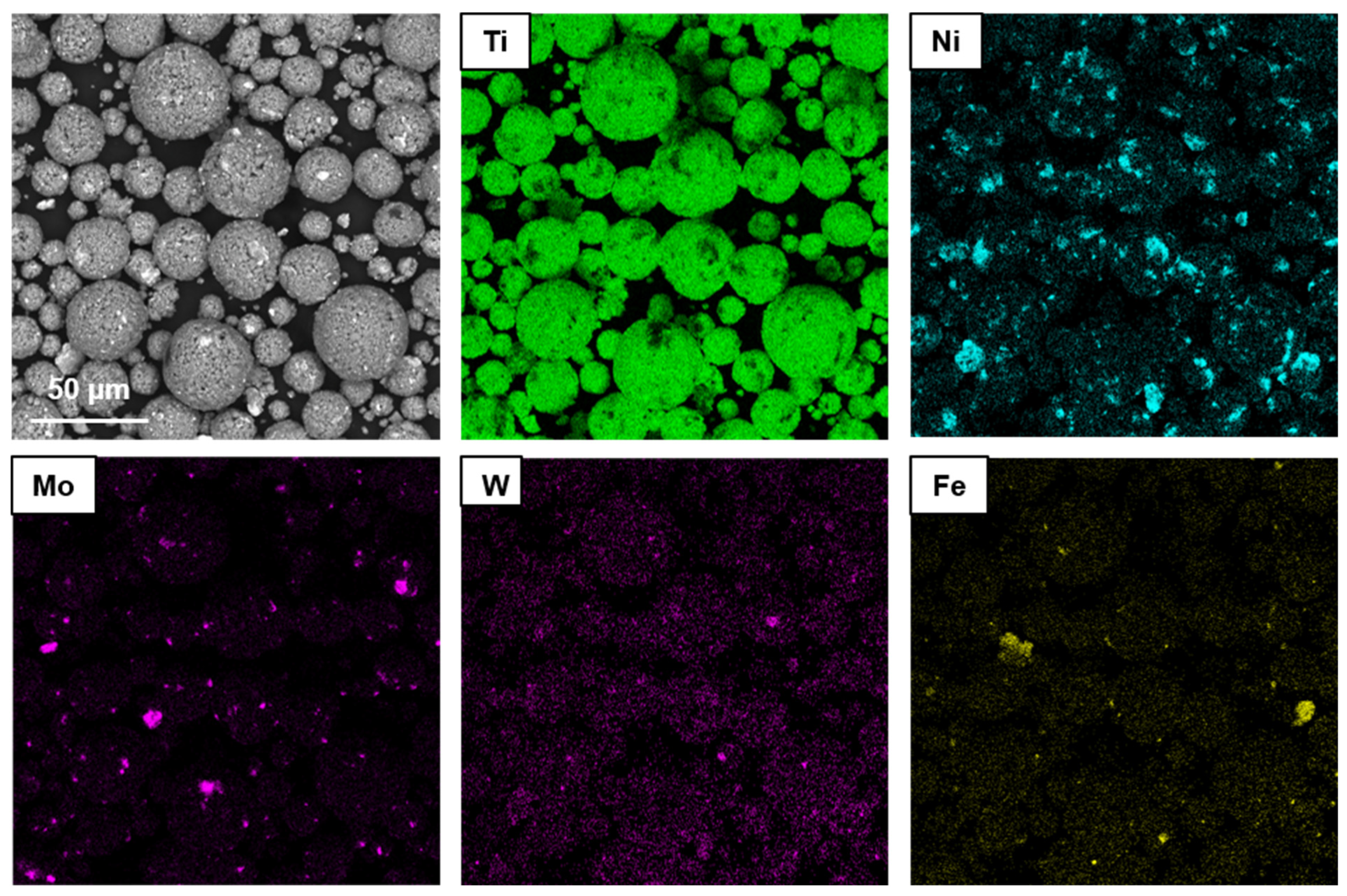
3.1. Fabrication of the Powder for L-DED

The first step to produce the powder for the L-DED process was mechanical alloying. MA was carried out to obtain a uniform distribution of the initial components in the volume of the powder. Figure 4 shows micrographs of the powders produced.
Using different modes and conditions of MA, it is also possible to synthesize an alloy from the starting elements [31,32]. However, as can be seen from Figure 4, MA for 3 h resulted in no synthesis of the alloy. At the same time, a uniform mixture of the initial components in the volume of the resulting powder occurs and a uniform powder mixture is formed that is confirmed by element distribution maps (Figure 5). Figure 4 also shows a presence of bright white regions with a size of about 1 μm that correspond both to the initial Mo particles and to the W caused by the wear of the grinding balls during the MA process (Figure 5). Figure 5 also shows some Fe content that is caused by the wear of the grinding balls as well. The MA process implies an intense mechanical action, so brittle particles of the initial powders are prone to destruction and after 3 h of MA, the fragmented-shape particles in the resulting mixture had a mean size of 4 μm.
The irregular shape of the particles makes it difficult to use such a powder in AT machines due to their low fluidity and the risk of clogging the nozzles. One of the requirements for the powders in the L-DED process is their spherical shape [33]. The most widely used methods to produce spherical particles are plasma spheroidization (PS) and gas atomization. The first process provides a temperature up to 104 °C that makes it possible to melt almost any material even during short-term exposure to plasma. The melted droplets retain a spherical shape upon cooling. However, according to the C-Ti phase diagram [34,35], at temperatures above 3600 °C, TiC does not exist in a liquid state. Thus, when using the PS method, the particles will sublimate from the solid state and then precipitate in the form of small particles with a size of less than 1 µm. A similar effect is observed in the PS process applied to materials based on the C-Si system [33]. For this reason, the PS method is inappropriate for manufacturing spherical powders of such systems. Gas atomization implies lower temperatures with a more flexible variation in their values depending on the material used. However, the melting points of TiC and Mo are quite high, which causes technical difficulties in their gas atomization. From this point of view, spray-drying is a more reasonable method to obtain spherical particles without the melting step.
Another requirement that powders for L-DED should meet is the particle size, which must lie in the range of 40–150 μm to effectively use the laser focal spot of L-DED machines [26]. In this work, after MA, the particle size is significantly smaller than required. In order to shape the particles and to enlarge them, the spray-drying method described in Section 2.1 was chosen. Figure 6 and Figure 7 show micrographs of the resulting particles and element distribution maps.
As can be seen from Figure 6 and Figure 7, after spray-drying, spherical composite agglomerates are formed from smaller particles. The particle sizes lie in the range of 10–100 μm while 70 vol.% of the particles were in the range of 45–75 μm. For this estimation, dimensions of 50 particles on the SEM images were analyzed. The method of laser diffractometry is not considered applicable in this case as it results in breaking up the agglomerates due to PVA dissolution in the water environment of a measuring device. It can be noted that the powder after SD mostly contains particles of the needed size. At the same time, the surface of the particles is quite dense, with a small number of spaces between the small particles of the initial elements. Thus, the resulting powder satisfies the requirements for use in the L-DED process.

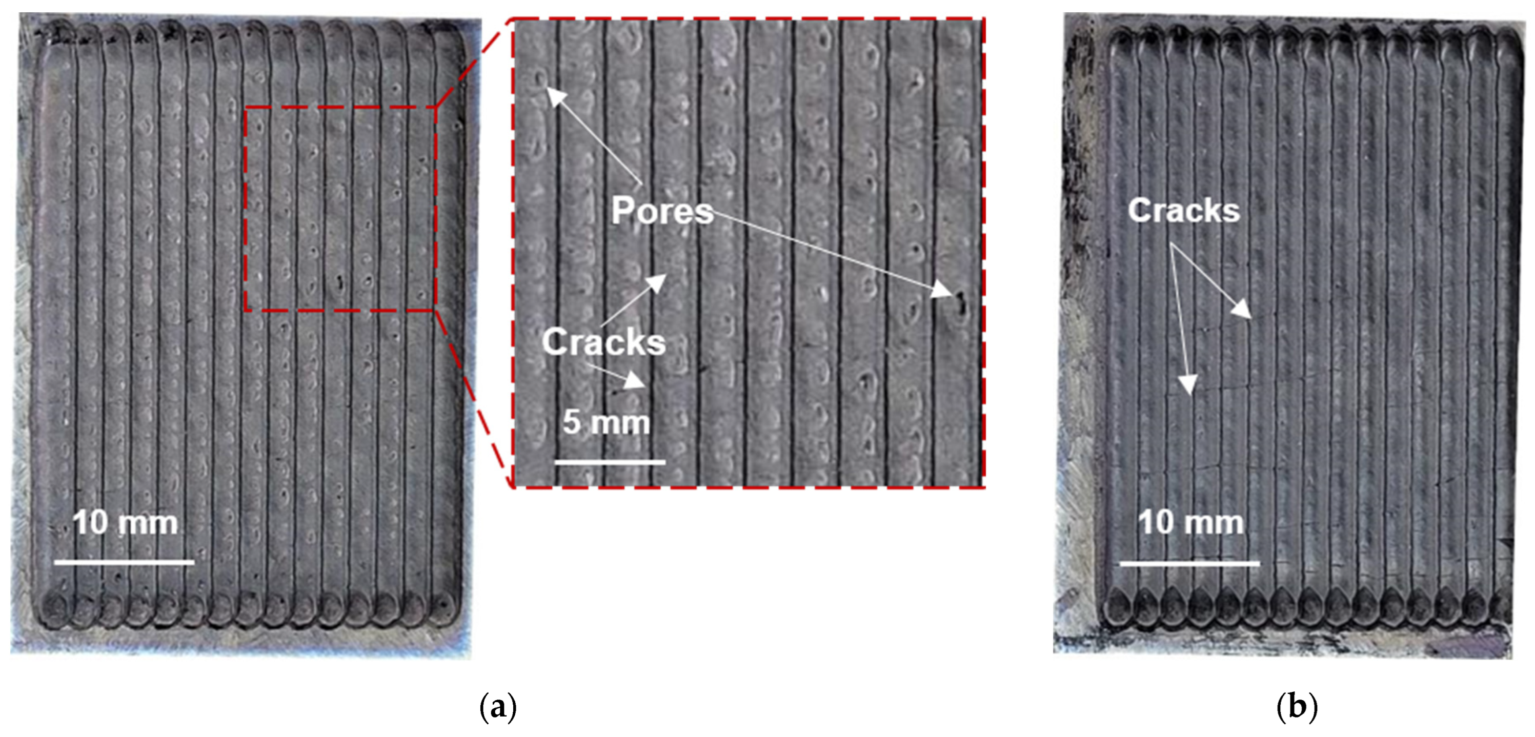
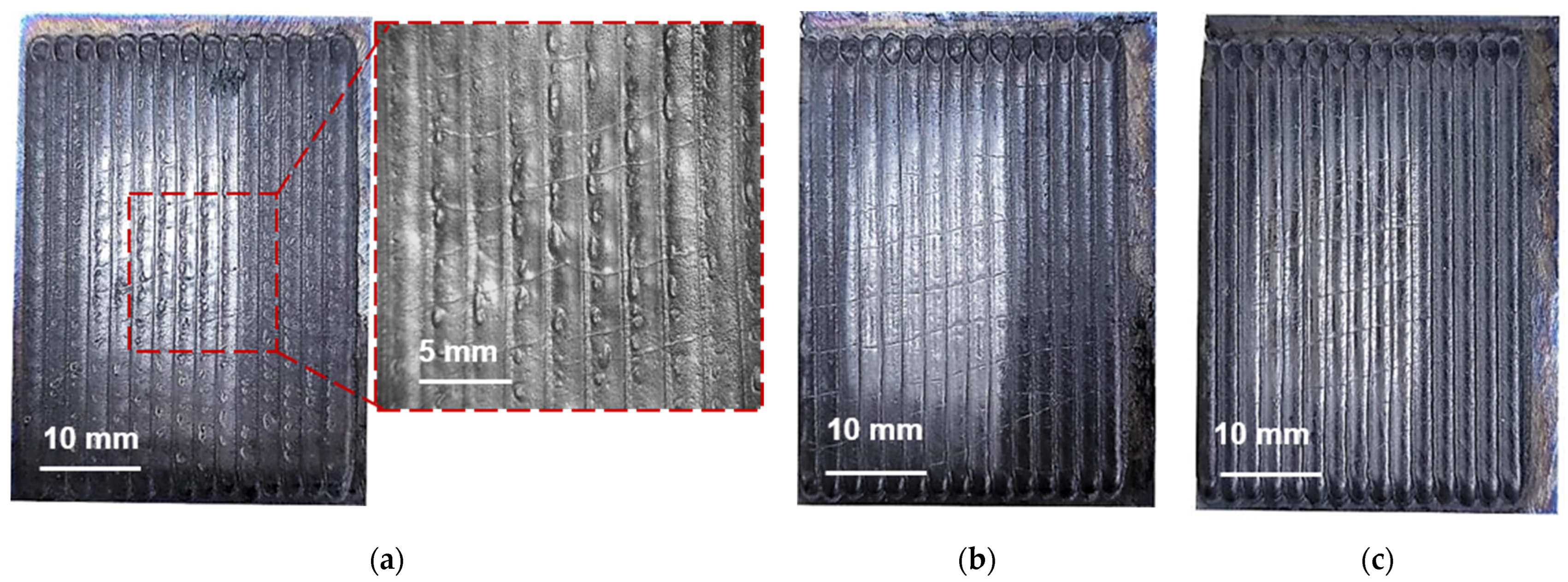
3.2. Coating Deposition by L-DED

Figure 8 shows the macrophotographs of the 1-layer (Figure 8a) and 2-layer (Figure 8b) samples produced by L-DED. The 1- and 2-layer samples show the presence of transverse cracks; the 1-layer sample also shows the presence of surface pores (Figure 8a). In the L-DED process, a gas–powder mixture is supplied into the melt pool zone with a rather high flow rate. In addition, L-DED technology provides a rather high cooling rate of about 103–104 K/s [36], which can, finally, result in the presence of pores in coatings produced by this method. To reduce the number and size of pores, a careful adjustment of the 3D printing modes by a consistent varying of all the technological parameters is required.
High cooling rates and significant temperature gradients common for ATs, including L-DED, also lead to the appearance of high internal stresses [25], which can result in the formation of cracks. The presence of such defects can decrease the general wear resistance due to faster brittle chipping at the defect sites and possible propagating of the cracks. In some cases, the cracks from the coating may pass to the substrate [37]. To obtain coatings without cracks, it is also necessary to optimize the technological parameters of L-DED. One of the most promising directions is to apply different scanning strategies such as rotating the successive layers by angles of 60–90° [38,39] to lower thermal stresses or to apply a double-scanning approach to cure pores formed and to improve the surface quality [40].
Nevertheless, despite the existing defects, the resulting coating had rather good adhesion upon visual inspection and did not peel off from the substrate. There was also no cleavage.

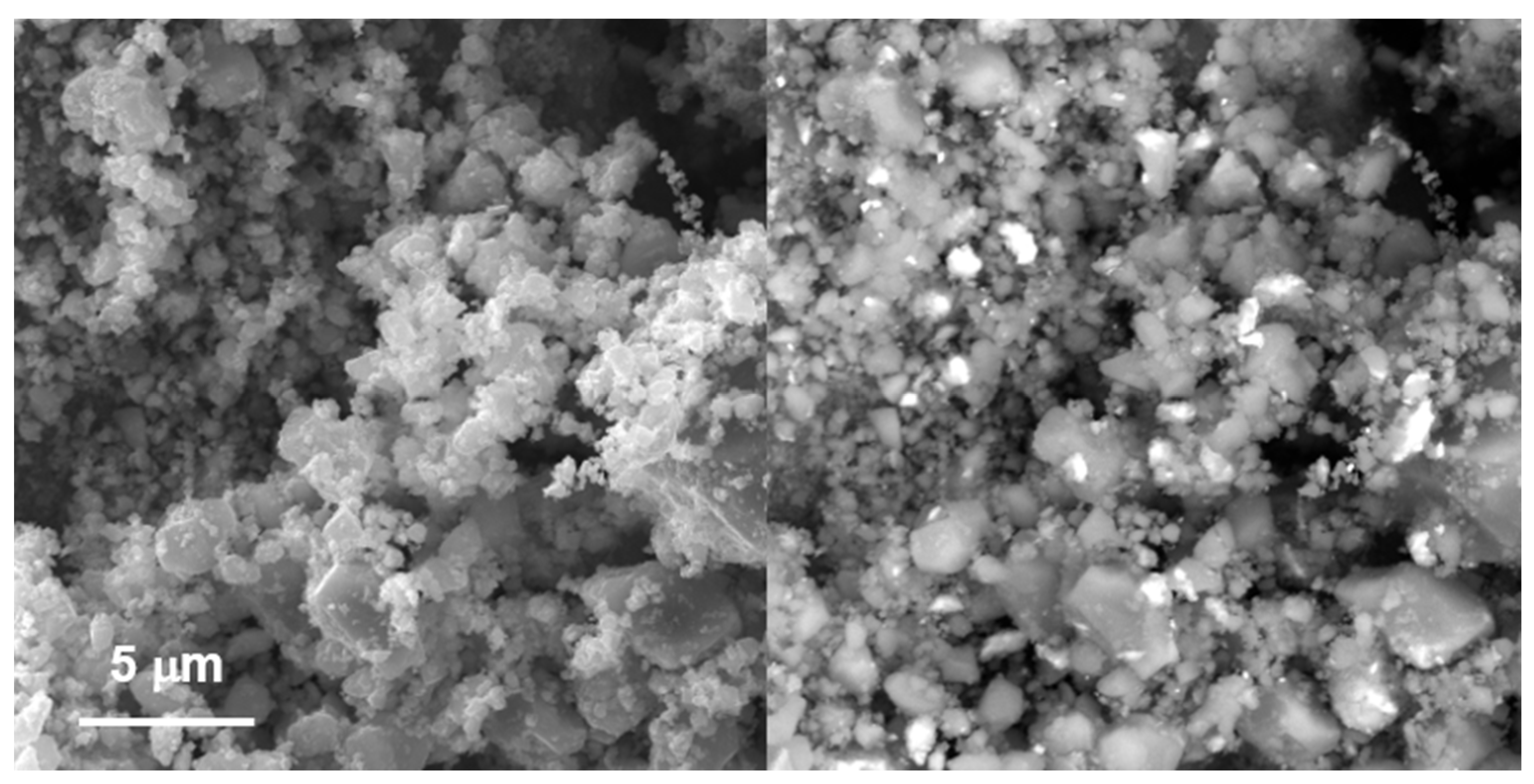
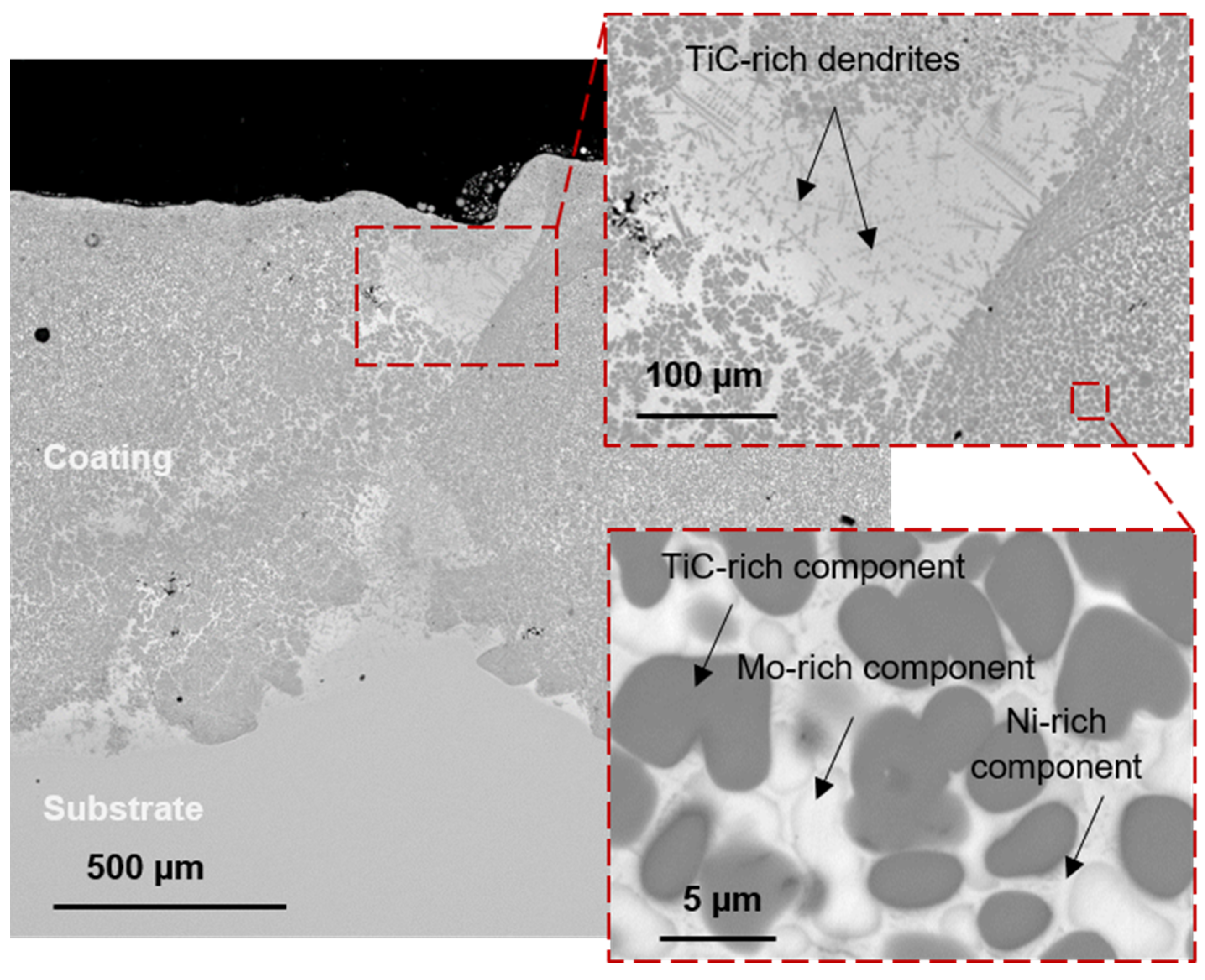
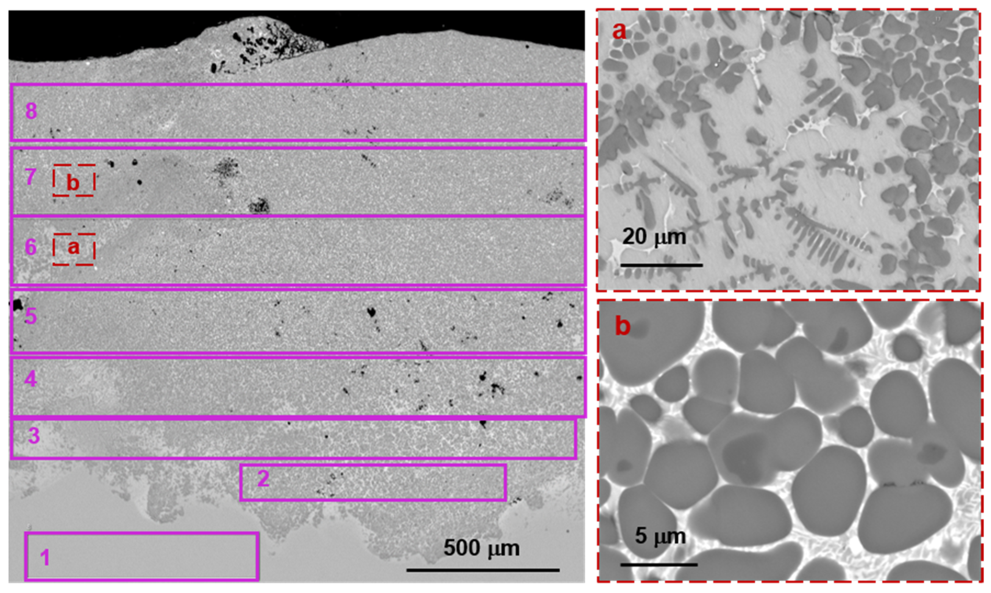
3.3. Coating Structure

Figure 9 shows the structure of the coating manufactured. Based on the SEM images of a cross-section of the coating, three main structural components (SC) can be distinguished: 1—dark gray round-shaped precipitates with a size of about 7 ± 2 μm, 2—light gray round-shaped precipitates with a clearly visible boundary with a similar size and 3—light gray areas between the precipitates. The average results of the elemental analysis are given in Table 2. The analysis was carried out without taking into account the oxygen content as EDS is not an appropriate method to determine it accurately. However, all three spectrums contained lines corresponding to oxygen. It can be explained by the high sensitivity of Ti-based alloys to oxygen. Thus, the presence of dissolved oxygen and some oxides in the coating cannot be excluded and it demands further investigations using other methods.
Carbon is another light element determined via EDS analysis. It is also impossible to accurately measure its content via this method. Moreover, its presence is always observed due to some carbon deposition in the SEM column. However, the obtained values can be used for comparison. Thus, in SC 1, the carbon content is significantly higher than in SC 2 and SC 3. It indicates that SC 1 is a carbon-containing component that corresponds to a TiC-rich component.
Based on the composition analysis of all areas that differ in contrast, it can be concluded that the dark gray areas are enriched with TiC, the light gray rounded areas are enriched with Mo and the intergrain component is enriched with Ni. There are also regions with TiC-based dendrites that are observed at the zones between tracks.
Since the melting points of TiC (3073 °C) and Mo (2623 °C) are significantly higher than the melting point of Ni (1455 °C), TiC and Mo crystallize first from the cooled melt after the laser beam passed and form solid precipitates of a nearly spherical shape. With the further cooling of the melt pool, Ni crystallizes between the particles of the already solidified phases, filling the free space between the precipitates. In this way, a composite material is formed with strengthening phases based on Mo and TiC, which have a high hardness. In this case, Ni, which fills the space between the solid particles and has good ductility, acts as a binder, preventing the brittle fracture of the material under conditions of increased wear.
Table 2 shows that in SCs 2 and 3, the presence of Al and V is also observed. These elements consist in the Ti-6Al-4V alloy used as the substrate. Thus, when applying a coating using the L-DED method, partial mixing of the applied powder with the substrate occurs when the laser beam forms a melt pool. It can also be seen that up to 2 wt.% W is found in the coating. It is mainly concentrated in the structural component enriched with Mo due to good mutual solubility. The appearance of W in the coating is explained by the wear of the hard alloy-based grinding balls used in the mill when mixing the initial powders.
Thus, when applying a coating using the L-DED method from the powders synthesized by preliminary MA, it is necessary to take into account changes in its elemental composition. However, W does not form separate precipitations, but dissolves in Mo and should not have a negative effect on the wear-resistant properties of the coating. It may also be noted that the coating thickness can influence its properties due to the presence of a mixing zone between the coating and the substrate.
The structure of the 2-layer coating is similar to the structure of the 1-layer coating (Figure 10). There are also TiC-rich and Mo-rich precipitates in the Ni-based binder and regions with TiC-based dendrites that are observed between adjoining tracks. However, TiC-rich precipitates are more numerous up to the surface of the coating. Table 3 shows the results of the EDS analysis of eight regions from the substrate to the surface of the coating. The regions are shown in Figure 10.
It can be seen that there is a gradient in chemical composition. The content of Ni and Mo gradually increases and achieves their targeted value at regions 7 and 8 that are at a distance of about 1 mm from the boundary formed between the coating and the substrate. Nevertheless, some amount of Al and V from the substrate is still observed in the regions close to the surface.

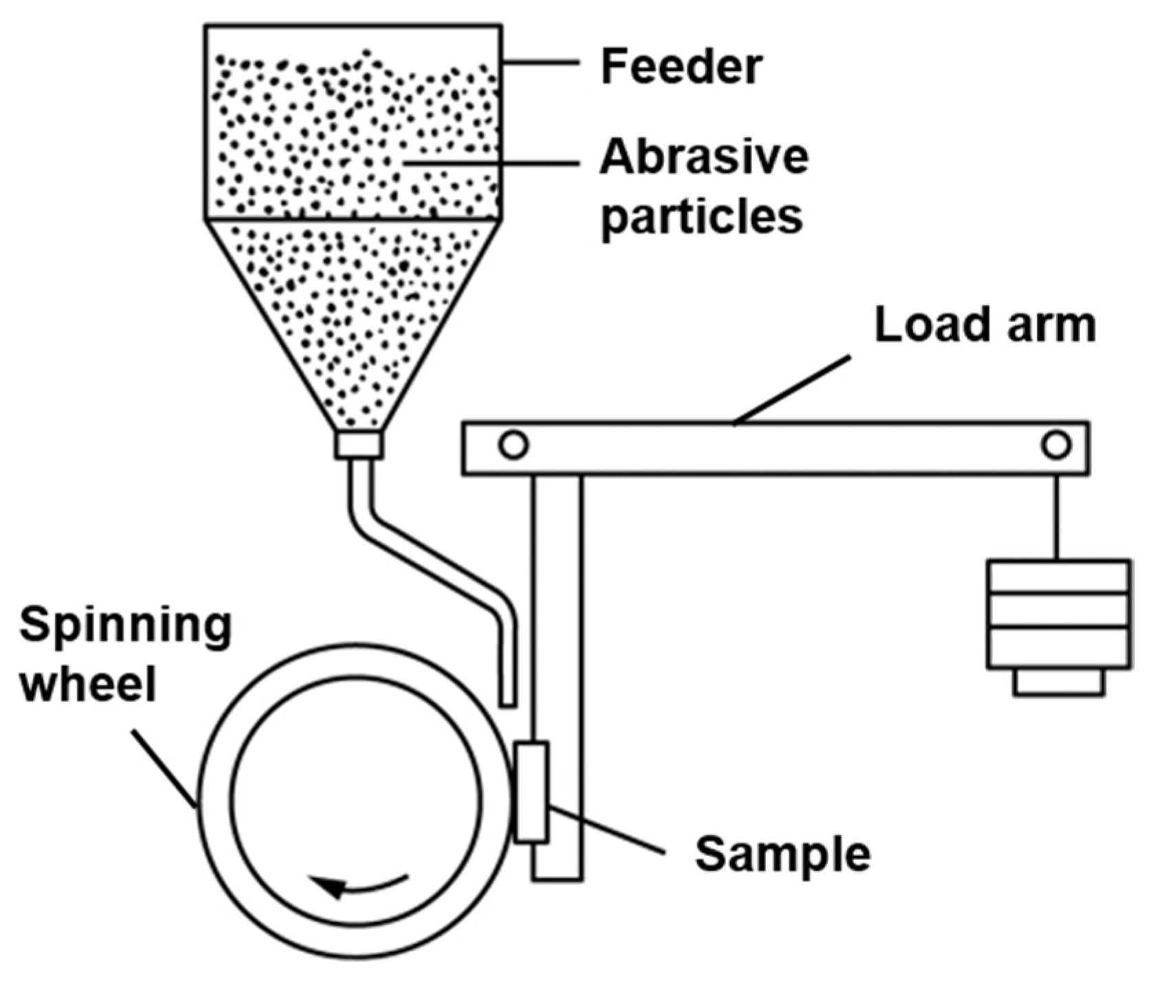
3.4. Wear Resistance of TiC-NiMo Coating Produced by L-DED

After applying 1- and 2-layer coatings onto the T—6Al-4V substrate, the samples were tested for wear resistance. The test results are shown in Table 4. For the 2-layer sample, two test cycles were carried out with intermediate measurements of the weight loss values.
Abrasive wear tests according to the ASTM G65 standard [30] are actively used in the oil industry to assess the wear resistance of coatings. It has some of the highest demands for this parameter. There is a common requirement that the weight loss of a sample after the testing should not exceed 0.24 g; however, specific values can also be set. For comparison, in papers [41,42], the weight loss of Fe-Cr-Nb-B alloys produced by various methods was in the range of 0.07–1.06 g. In paper [43], the weight loss of a Ti-6Al-4V alloy produced by electron beam melting was 0.049285 g after 2000 wheel revolutions. Thus, the coating deposited in this paper shows a high wear resistance and provides a better wear resistance to the Ti-based substrate.
A mass loss of 0.0464 g obtained after 4000 revolutions also corresponds to a volumetric loss of 7.96 mm3 estimated by Equation (1) [44]:
ΔV = (Δm/ρ) × 1000,
where Δm is the mass loss, g; ρ = 5.83 g/cm3 is the coating density estimated by using the components ratio.
From the volumetric loss, the dimensional wear coefficient per unit sliding distance can also be estimated according to the Archard model and Equation (2) [44]:
k = ΔV/(FN × D),
where FN is the normal load, N; D = 5727 m is the sliding distance after 4000 wheel revolutions.
Thus, k = 1.07 × 10⁻⁵ mm3/(Nm). In papers [45,46], the coefficient was more than 2 × 10⁻⁵ mm3/(Nm) for TiC-NiMo systems fabricated by PM methods with various values of binder content. This fact indicates the higher wear resistance of the TiC-NiMo coating deposited by the L-DED method using the selected components ratio and technological parameters. It should also be noted that TiC-NiMo cermets are still somewhat inferior to WC-Co hard alloys, as the latter can show a k of about 0.5 × 10⁻⁵ mm3/(Nm) [43,44]. Nevertheless, the results obtained are considered competitive and can be further improved by implementing other L-DED modes and an optimized components ratio.
Abrasive wear usually causes notable wear scratches on the materials’ surface such as long and deep scars [43,47]. Figure 11 shows the appearance of the TiC-NiMo samples produced by L-DED after abrasive wear testing. As can be seen from the Figure, the samples after wear tests contain almost the same defects, including surface pores and transverse cracks, as before the tests (Figure 8). No new defects, including any wear scratches, appear, and there is no cleavage or peeling off of the coating from the substrate that can indicate its good durability. However, it should be studied more thoroughly using longer tests.
Wear resistance of materials is largely determined by their hardness. The average hardness of the 1-layer and 2-layer TiC-NiMo coatings was 885 HV and 1070, respectively. The lower hardness in the case of the 1-layer coating may be associated with its higher porosity. However, the main reason is considered to be the fact that the mixing zone in a 1-layer coating more significantly contributes to the total hardness as its own hardness is lower due to the lower hardness of the substrate material. In the 1-layer coating, the mixing zone has a higher relative volume in comparison to the 2-layer coating.
After the wear tests, the average hardness values decreased slightly to 856 HV and 1054 HV, respectively. At the same time, numerous measurements at different points of the coating showed a significant scatter of values, which is most likely due to the presence of several structural components and the heterogeneity of their distribution. For example, areas with dendrites showed an average hardness of 481 HV, and fine-grained areas with a denser arrangement of TiC precipitates showed an average hardness of 1232 HV with separate points of hardness close to 1500 HV.
The most pronounced anisotropy of hardness was found in the 2-layer samples. The highest hardness values, more than 1000 HV, were observed close to the coating surface. It can be associated with the fact that when moving away from the substrate towards the surface, there is a transition from the mixing zone to the coating material itself. There can also take place a contribution of some TiC floating in the melt pool. As was mentioned above, TiC is the first to crystallize in the melt pool. As it has a lower density than other components in the composition used, it may have a tendency to float in the liquid metal. For example, such an effect was observed when ceramic particles were used for ATs in papers [27,28].
To compare the results with other wear-resistant coatings of similar compositions, the following data can be discussed. For example, in paper [21], in situ synthesis of TiC by L-DED was studied. In the melt pools, precursors in the form of Ti powder interacted with Ni particles coated with carbon that led to TiC formation in the Ni matrix. It was found that the sample with 50 wt.% of Ni had a hardness of about 1075 HV.
In paper [48], (Fe,Ni)-TiC composites produced by the DMLS method were studied. The study showed that reducing the TiC content from 80 wt.% down to 30 wt.% allowed for obtaining products with a more accurate geometry and absence of cracks, but with a lower hardness (380 HV), the specific wear rate at 30 wt.% TiC was 8 × 10⁻⁶ mm3/N·m.
In general, the hardness of coatings with similar TiC-Ni-Mo compositions produced by L-DED methods can vary in a rather wide range from 740 to 2200 HV [10,23]. It is determined by numerous factors such as the element ratio in the coating, as well as the size of the structural components. An increase in the Ni content reduces the brittleness of the coating, but at the same time, also reduces the hardness [10]. An increase in hardness is provided by structure refinement [21]. Thus, the resulting coatings have a rather high hardness that is not inferior to the published data on similar L-DED coatings, as well as on TiC-NiMo composites produced by conventional PM methods. The hardness of the latter varies from 1000 to 1500 HV [3,49].
For bulk materials, the dependence of the wear resistance on the hardness values is almost linear [44]. A high hardness determines the resistance of a material to normal stresses. However, the abrasive wear implies mainly tangent stresses. In this case, the stress resistance significantly depends on the material’s ductile properties. For composite materials, a rather important parameter is the size of the structural components. In abrasive wear, the main acting factor is an impact of separate abrasive particles at a high speed. If the size of the hard structural component in the ductile matrix and the intergranual regions are comparable to the size of the abrasive particles, then the composite material will behave heterogeneously [42]. In this case, the abrasive particles will lead to the fracture of the hard particles and to the plastic flow of the binder regions, resulting in a general low-wear resistance despite the high average hardness of the material. In the present study, SCs have a size of about 7 μm that is much less than the size of the abrasive particles used. In this case, the coating behaves as a solid homogeneous material with a high resistance to abrasive wear.
For TiC-Ni compositions, a drop in the volume loss is generally observed at hardness values of about 1300 HV [45]. The wear resistance of a material also depends on the material of abrasive particles used. If its hardness (Ha) is 1.2 or more times higher than that of the tested material (Hm), then the “hard” mechanism of wear will take place, causing high wear rates [45,46]. If the Ha/Hm ratio is less than 1.2, then the “soft” wear mechanism with much lower wear rates will be observed. In this work, quartz SiO2 abrasive particles were used. Commonly, their hardness is about 1150 HV, and Ha/Hm is 0.8–0.9 for the coating surface hardness of 1232–1500 HV in this work. It indicates the “soft” wear mechanism in this case. Thus, the TiC-NiMo coating produced by L-DED exhibits a good wear resistance and can be applied in abrasive environments with the abrasive particles’ hardness up to 1800 HV such as various aluminosilicates.
The results of wear tests depend not only on the hardness values, but also on the test methodology, which often makes it very difficult to compare experimental data with published ones. In addition, there is practically no published data on the wear resistance of L-DED coatings of the TiC-NiMo system. However, in this work, even after 4000 revolutions of the abrasive disk of the tribological testing machine, the studied 2-layer sample almost did not lose weight and showed a rather low wear rate. In combination with the preservation of the coating appearance without any visible formation of new defects and cleavage after testing, the obtained results suggest a high level of wear resistance of the coating obtained in this work, despite the presence of initial cracks and pores. Further optimization of the composition and technological parameters of L-DED at all steps can help to improve the performance of the wear-resistant TiC-NiMo coatings, which makes this method rather promising. One of the favorable directions is an application of new scanning strategies such as changing an angle between the layers and also double scanning by the laser beam aimed at eliminating hot cracks and to improve the surface quality.

4. Conclusions

This work shows the fundamental possibility of producing a wear-resistant composite TiC-NiMo coating on a Ti-6Al-4V substrate by L-DED technology, using TiC, Ni and Mo powders as the initial materials.
It was demonstrated that the combination of 3 h of mechanical alloying and subsequent spray-drying allowed for the fabrication of a spherical composite TiC-NiMo powder with a rather uniform distribution of the elements and with a size of 70 vol.% of the particles in the range of 45–75 µm. Such a powder was successfully used in the L-DED process.
TiC-NiMo coatings produced by L-DED are prone to cracking, but do not peel off from the substrate and possess a good adhesion.
The average hardness of the 1-layer and 2-layer TiC-NiMo coatings was 856 HV and 1054 HV, respectively. The hardness of a 2-layer coating increases in the direction from the substrate to the surface due to the presence of a mixing zone between the substrate material and the coating material, which especially affects coatings with fewer layers. Near the surface of the 2-layer coating, its hardness reached values up to 1500 HV, which are comparable to the similar compositions produced by conventional PM methods.
Due to the fine-grain structure with reinforcing TiC-rich and Mo-rich precipitates in the Ni-based binder, the composite TiC-NiMo coatings produced by L-DED showed a high wear resistance determined by the dimensional wear coefficient per unit sliding distance of 1.07 × 10⁻⁵ mm3/(Nm) that is lower than that of traditionally manufactured TiC-based cermets and comparable to that of WC-based hard alloys.
It was shown that due to the high hardness, low wear rates and high adhesion, the TiC-NiMo composite coating produced by L-DED is promising for its application in high-wear environments to improve the durability of critical parts such as oil production equipment elements that work in the hardest abrasive wear conditions.
Additional optimization of the composition and technological parameters of L-DED at all steps can help to further improve the performance of the wear-resistant TiC-NiMo coatings. One of the most promising directions is to apply different scanning strategies such as rotating the successive layers by angles of 60–90° to lower thermal stresses or to apply double scanning to cure the pores formed and to improve the surface quality.

Author Contributions

Conceptualization, N.R. and D.M.; data curation, A.M.; investigation, A.M., M.K. and E.V.; methodology, N.R. and D.M.; project administration, N.R.; resources, A.P.; supervision, A.P.; writing—original draft, A.M.; writing—review and editing, D.M. and A.P. All authors have read and agreed to the published version of the manuscript.

Funding

The research is partially funded by the Ministry of Science and Higher Education of the Russian Federation as part of the World-class Research Center program: Advanced Digital Technologies (contract No. 075-15-2022-311 dated 20 April 2022).

Institutional Review Board Statement

Not applicable.

Informed Consent Statement

Not applicable.

Data Availability Statement

The research data are available on request.

Conflicts of Interest

The authors declare no conflict of interest.

References

  1. Ettmayer, P. Hardmetals and Cermets. Annu. Rev. Mater. Sci. 1989, 19, 145–164. [Google Scholar] [CrossRef]
  2. Mari, D. Cermets and Hardmetals. Encycl. Mater. Met. Alloy. 2016, 1, 420–424. [Google Scholar] [CrossRef]
  3. Aramian, A.; Sadeghian, Z.; Narimani, M.; Razavi, N.; Berto, F. A review on the microstructure and properties of TiC and Ti(C,N) based cermets. Int. J. Refract. Met. Hard Mater. 2023, 115, 106320. [Google Scholar] [CrossRef]
  4. Zhao, Y.; Li, R.; Wu, M.; Yue, H.; Li, T.; Chen, Y. Effect of c-BN on the microstructure and high temperature wear resistance of laser cladded Ni-based composite coating. Surf. Coat. Technol. 2021, 421, 127466. [Google Scholar] [CrossRef]
  5. Wang, Z.; Zhou, M.; Zhu, M.; Jiang, Y.; Sui, Y. Effect of precursor density on the wear resistance of in-situ TiC/Fe matrix composites based on Fe–Cr system moderator. Ceram. Int. 2023, 49, 18925–18936. [Google Scholar] [CrossRef]
  6. Zhao, W.; Yu, K.; Ma, Q.; Song, C.; Xiao, G.; Zhang, H.; Lv, Y.; Guo, N.; Li, Z. Synergistic effects of Mo and in-situ TiC on the microstructure and wear resistance of AlCoCrFeNi high entropy alloy fabricated by laser cladding. Tribol. Int. 2023, 188, 108827. [Google Scholar] [CrossRef]
  7. Gopinath, V.M.; Arulvel, S. A review on the steels, alloys/high entropy alloys, composites and coatings used in high temperature wear applications. Mater. Today Proc. 2020, 43, 817–823. [Google Scholar] [CrossRef]
  8. Maurya, H.S.; Juhani, K.; Sergejev, F.; Prashanth, K.G. Additive manufacturing of TiC-based cermet with stainless steel as a binder material. Mater. Today Proc. 2022, 57, 824–828. [Google Scholar] [CrossRef]
  9. Das, K.; Bandyopadhyay, T.K.; Das, S. A review on the various synthesis routes of TiC reinforced ferrous based composites. J. Mater. Sci. 2002, 37, 3881–3892. [Google Scholar] [CrossRef]
  10. Li, Y.; Bai, P.; Wang, Y.; Hu, J.; Guo, Z. Effect of Ni contents on the microstructure and mechanical properties of TiC-Ni cermets obtained by direct laser fabrication. Int. J. Refract. Met. Hard Mater. 2009, 27, 552–555. [Google Scholar] [CrossRef]
  11. Sahoo, C.K.; Masanta, M. Microstructure and mechanical properties of TiC-Ni coating on AISI304 steel produced by TIG cladding process. J. Mater. Process. Technol. 2017, 240, 126–137. [Google Scholar] [CrossRef]
  12. Sufiiarov, V.; Erutin, D.; Borisov, E.; Popovich, A. Selective Laser Melting of Inconel 718/TiC Composite: Effect of TiC Particle Size. Metals 2022, 12, 1729. [Google Scholar] [CrossRef]
  13. Li, R.; Han, B.; Zhao, K.; Wang, Z.; Shi, Y.; Bi, K.; Sun, G. Effects of TiC addition on the hot corrosion behavior of IN718 fabricated by laser direct metal deposition. Mater. Chem. Phys. 2023, 308, 128167. [Google Scholar] [CrossRef]
  14. Navarrete-Cuadrado, J.; Soria-Biurrun, T.; Lozada-Cabezas, L.; Ibarreta-López, F.; Martínez-Pampliega, R.; Sánchez-Moreno, J.M. Effect of pressure on sintering of TiC-Fe-Cr-Mo cermets under vacuum conditions. Int. J. Refract. Met. Hard Mater. 2023, 114, 106262. [Google Scholar] [CrossRef]
  15. Gao, W.; Zhou, Y.; Cai, R.; Wu, S.; Zhang, Z.; Zhao, Y.; Huang, Z.; Li, S. Fabrication, mechanical properties, and wear behaviors of co-continuous TiC-steel composites. Mater. Charact. 2022, 190, 112051. [Google Scholar] [CrossRef]
  16. Maurya, H.S.; Jayaraj, J.; Vikram, R.J.; Juhani, K.; Sergejev, F.; Prashanth, K.G. Additive manufacturing of TiC-based cermets: A detailed comparison with spark plasma sintered samples. J. Alloys Compd. 2023, 960, 170436. [Google Scholar] [CrossRef]
  17. Maurya, H.S.; Jayaraj, J.; Wang, Z.; Juhani, K.; Sergejev, F.; Prashanth, K.G. Investigation of the tribological behavior of the additively manufactured TiC-based cermets by scratch testing. J. Alloys Compd. 2023, 959, 170496. [Google Scholar] [CrossRef]
  18. DebRoy, T.; Wei, H.L.; Zuback, J.S.; Mukherjee, T.; Elmer, J.W.; Milewski, J.O.; Beese, A.M.; Wilson-Heid, A.; De, A.; Zhang, W. Additive manufacturing of metallic components—Process, structure and properties. Prog. Mater. Sci. 2018, 92, 112–224. [Google Scholar] [CrossRef]
  19. Herzog, D.; Seyda, V.; Wycisk, E.; Emmelmann, C. Additive manufacturing of metals. Acta Mater. 2016, 117, 371–392. [Google Scholar] [CrossRef]
  20. Saeidi, K.; Kvetková, L.; Lofaj, F.; Shen, Z. Austenitic stainless steel strengthened by the in situ formation of oxide nanoinclusions. RSC Adv. 2015, 5, 20747–20750. [Google Scholar] [CrossRef]
  21. Chen, L.; Zhao, Y.; Meng, F.; Yu, T.; Ma, Z.; Qu, S.; Sun, Z. Effect of TiC content on the microstructure and wear performance of in situ synthesized Ni-based composite coatings by laser direct energy deposition. Surf. Coat. Technol. 2022, 444, 128678. [Google Scholar] [CrossRef]
  22. Chen, L.; Zhao, Y.; Chen, X.; Yu, T.; Xu, P. Repair of spline shaft by laser-cladding coarse TiC reinforced Ni-based coating: Process, microstructure and properties. Ceram. Int. 2021, 47, 30113–30128. [Google Scholar] [CrossRef]
  23. Sun, X.; Ren, X.; Qiang, W.; Feng, Y.; Zhao, X.; Huang, B. Microstructure and properties of Inconel 718 matrix composite coatings reinforced with submicron TiC particles prepared by laser cladding. Appl. Surf. Sci. 2023, 637, 157920. [Google Scholar] [CrossRef]
  24. Popovich, A.A.; Sufiyarov, V.S.; Razumov, N.G.; Borisov, E.V.; Masailo, D.V.; Goncharov, I.S. Materials and Additive Technologies. Modern Materials for Additive Technologies; SPbSTU: St. Petersburg, Russia, 2021. [Google Scholar]
  25. Cheng, J.; Xing, Y.; Dong, E.; Zhao, L.; Liu, H.; Chang, T.; Chen, M.; Wang, J.; Lu, J.; Wan, J. An Overview of Laser Metal Deposition for Cladding: Defect Formation Mechanisms, Defect Suppression Methods and Performance Improvements of Laser-Cladded Layers. Materials 2022, 15, 5522. [Google Scholar] [CrossRef] [PubMed]
  26. Korsmik, R.; Zadykyan, G.; Tyukov, S.; Klimova-Korsmik, O.; Dmitrieva, A. Prediction of Occurrence of Hot Cracks in Laser Cladding Heat Resistant Nickel Alloys. Metals 2023, 13, 1751. [Google Scholar] [CrossRef]
  27. Shi, Y.; Lu, Z.; Xu, H.; Xie, R.; Ren, Y.; Yang, G. Microstructure characterization and mechanical properties of laser additive manufactured oxide dispersion strengthened Fe-9Cr alloy. J. Alloys Compd. 2019, 791, 121–133. [Google Scholar] [CrossRef]
  28. Wilms, M.B.; Rittinghaus, S.K.; Goßling, M.; Gökce, B. Additive manufacturing of oxide-dispersion strengthened alloys: Materials, synthesis and manufacturing. Prog. Mater. Sci. 2023, 133, 101049. [Google Scholar] [CrossRef]
  29. ISO 6507-1:2023; Metallic Materials. Vickers Hardness Test. Part 1: Test Method. International Organization for Standardization: Geneva, Switzerland, 2023.
  30. ASTM G65-16(2021); Standard Test Method for Measuring Abrasion Using the Dry Sand/Rubber Wheel Apparatus. ASTM: West Conshohocken, PA, USA, 2021.
  31. Koch, C.C.; Whittenberger, J.D. Mechanical milling/alloying of intermetallics. Intermetallics 1996, 4, 339–355. [Google Scholar] [CrossRef]
  32. Radev, D.D. Mechanical synthesis of nanostructured titanium-nickel alloys. Adv. Powder Technol. 2010, 21, 477–482. [Google Scholar] [CrossRef]
  33. Popovich, A.; Sufiiarov, V. Metal powder additive manufacturing. In New Trends in 3D Printing; Shishkovsky, I.V., Ed.; IntechOpen: Rijeka, Croatia, 2016; p. 22. [Google Scholar]
  34. Liakishev, N.P. (Ed.) Phase Diagrams of Binary Metal Systems: Handbook: In 3 Vol., V.1; Mashinostroenie: Moscow, Russia, 1996. [Google Scholar]
  35. Polozov, I.; Razumov, N.; Masaylo, D.; Silin, A.; Lebedeva, Y.; Popovich, A. Fabrication of Silicon Carbide Fiber-Reinforced Silicon Carbide Matrix Composites Using Binder. Materials 2020, 13, 1766. [Google Scholar] [CrossRef]
  36. Jeong, J.; Webster, S.; Liao, S.; Mogonye, J.-E.; Ehmann, K.; Cao, J. Cooling rate measurement in directed energy deposition using photodiode-based planck thermometry (PDPT). Addit. Manuf. Lett. 2022, 3, 100101. [Google Scholar] [CrossRef]
  37. Korotkov, V.A. Crack and Wear Resistance of Hard Coatings. Russ. Eng. Res. 2021, 41, 1131–1134. [Google Scholar] [CrossRef]
  38. Ribeiro, K.S.B.; Mariani, F.E.; Coelho, R.T. A Study of Different Deposition Strategies in Direct Energy Deposition (DED) Processes. Procedia Manuf. 2020, 48, 663–670. [Google Scholar] [CrossRef]
  39. Haghdadi, N.; Laleh, M.; Moyle, M.; Primig, S. Additive manufacturing of steels: A review of achievements and challenges. J. Mater. Sci. 2021, 56, 64–107. [Google Scholar] [CrossRef]
  40. Errico, V.; Fusco, A.; Campanelli, S.L. Effect of DED coating and DED + Laser scanning on surface performance of L-PBF stainless steel parts. Surf. Coat. Technol. 2022, 429, 127965. [Google Scholar] [CrossRef]
  41. Górka, J.; Czupryński, A.; Zuk, M.; Adamiak, M.; Kopyść, A. Properties and structure of deposited nanocrystalline coatings in relation to selected construction materials resistant to abrasive wear. Materials 2018, 11, 1184. [Google Scholar] [CrossRef] [PubMed]
  42. Bahoosh, M.; Shahverdi, H.R.; Farnia, A. Abrasive Wear Behavior and Its Relation with the Macro-indentation Fracture Toughness of an Fe-Based Super-Hard Hardfacing Deposit. Tribol. Lett. 2019, 67, 100. [Google Scholar] [CrossRef]
  43. Herrera, P.; Hernandez-Nava, E.; Thornton, R.; Slatter, T. Abrasive wear resistance of Ti-6AL-4V obtained by the conventional manufacturing process and by electron beam melting (EBM). Wear 2023, 524–525, 204879. [Google Scholar] [CrossRef]
  44. de Sousa, J.M.S.; Ratusznei, F.; Pereira, M.; Castro, R.d.M.; Curi, E.I.M. Abrasion resistance of Ni-Cr-B-Si coating deposited by laser cladding process. Tribol. Int. 2020, 143, 106002. [Google Scholar] [CrossRef]
  45. Kübarsepp, J.; Juhani, K.; Tarraste, M. Abrasion and erosion resistance of cermets: A review. Materials 2022, 15, 69. [Google Scholar] [CrossRef]
  46. Pirso, J.; Viljus, M.; Letunovitš, S.; Juhani, K.; Joost, R. Three-body abrasive wear of cermets. Wear 2011, 271, 2868–2878. [Google Scholar] [CrossRef]
  47. Tomkow, J.; Czupryński, A.; Fydrych, D. The Abrasive Wear Resistance of Coatings Manufactured on High-Strength Low-Alloy (HSLA) Offshore Steel in Wet Welding Conditions. Coatings 2020, 10, 219. [Google Scholar] [CrossRef]
  48. Gåård, A.; Krakhmalev, P.; Bergström, J. Microstructural characterization and wear behavior of (Fe,Ni)-TiC MMC prepared by DMLS. J. Alloys Compd. 2006, 421, 166–171. [Google Scholar] [CrossRef]
  49. Fu, Z.; Kong, J.H.; Gajjala, S.R.; Koc, R. Sintering, mechanical, and oxidation properties of TiC-Ni-Mo cermets obtained from ultra-fine TiC powders. J. Alloys Compd. 2018, 751, 316–323. [Google Scholar] [CrossRef]
Figure 1. Microphotographs of initial powders of (a) TiC, (b) Ni, (c) Mo. Images were obtained using scanning electron microscope with a secondary electron detector.
Metals 13 01925 g001
Figure 2. Schematic of cross-sections of 1-layer and 2-layer coatings in the L-DED process.
Metals 13 01925 g002
Figure 3. Diagram of the testing setup for wear determination.
Metals 13 01925 g003
Figure 4. SEM images of TiC + Ni + Mo powder mixture after MA by mode 200/−400 3 h. The (left) image was obtained using SE detector, the (right) image was obtained using BSE detector.
Metals 13 01925 g004
Figure 5. BSE-image and element distribution maps of TiC-NiMo powder after MA. Meaning of the colors: green—Ti; blue—Ni; purple—Mo; rose—W; yellow—Fe.
Metals 13 01925 g005
Figure 6. Morphology of TiC-NiMo composite particles after spray-drying. The images were obtained using SE detector at the magnifications of ×500 (the (left) image) and ×5000 (the (right) image).
Metals 13 01925 g006
Figure 7. BSE-image and element distribution maps of TiC-NiMo composite powder after spray-drying. Meaning of the colors: green—Ti; blue—Ni; purple—Mo; rose—W; yellow—Fe.
Metals 13 01925 g007
Figure 8. Surface of TiC-NiMo composite: (a) 1-layer and (b) 2-layer samples produced by L-DED.
Metals 13 01925 g008
Figure 9. SEM images of the structure of the 1-layer TiC-NiMo composite coating produced by L-DED on a Ti-6Al-4V substrate. The image was obtained using BSE detector.
Metals 13 01925 g009
Figure 10. SEM images of the structure of the 2-layer TiC-NiMo composite coating produced by L-DED on a Ti-6Al-4V substrate. The images were obtained using BSE detector. Regions 1–8 are the zones for EDS analysis. Region (a) was observed at the magnification of ×3000 and region (b) was observed at the magnification of ×5000.
Metals 13 01925 g010
Figure 11. Appearance of TiC-NiMo samples after abrasion wear tests: (a) 1-layer sample after 2000 revolutions; (b) 2-layer sample after 2000 revolutions; (c) 2-layer sample after 4000 revolutions.
Metals 13 01925 g011
Table 1. L-DED mode.
ParameterValue
Overlap, %30
Power, kW2.2
Velocity, mm/s25
Flow rate, g/min39
Table 2. Average element content in structural components in the TiC-NiMo coating produced by L-DED method on a Ti-6Al-4V substrate.
Structural ComponentsCAlTiVFeNiMoW
Weight %
114.60.181.90.4-0.41.10.4
24.74.864.82.40.39.212.11.9
35.23.862.31.00.525.11.90.2
Table 3. Chemical composition of the 2-layer L-DED TiC-NiMo composite coating across its thickness.
RegionAlTiVFeNiMoW
Weight %
15.2292.71.940.110.0200
22.2383.920.970.167.813.51.23
32.7586.501.090.136.062.331.05
42.3387.250.990.076.052.390.81
51.7384.490.990.177.993.570.96
61.2680.50.850.229.795.331.95
70.7278.630.550.2412.716.080.82
80.4674.20.480.3514.956.982.32
Table 4. Weight loss of TiC-NiMo coatings after abrasive wear tests.
SampleWeight Loss, g
2000 Revolutions
Mass Loss, g
4000 Revolutions
Total Mass Loss, g
1-layer0.0341--
2-layer0.03300.01340.0464
Disclaimer/Publisher’s Note: The statements, opinions and data contained in all publications are solely those of the individual author(s) and contributor(s) and not of MDPI and/or the editor(s). MDPI and/or the editor(s) disclaim responsibility for any injury to people or property resulting from any ideas, methods, instructions or products referred to in the content.

