Article

Research on Buckling Load of Cylindrical Shell with an Inclined through Crack under External Pressure and Its Solution

1
School of Mechanical and Power Engineering, Nanjing Tech University, Nanjing 211816, China
2
Jiangsu Key Lab of Design and Manufacture of Extreme Pressure Equipment, Nanjing 211816, China
*
Author to whom correspondence should be addressed.
Metals 2023, 13(1), 174; https://doi.org/10.3390/met13010174
Submission received: 19 December 2022 / Revised: 11 January 2023 / Accepted: 11 January 2023 / Published: 15 January 2023
(This article belongs to the Special Issue Fracture Mechanics of Metals)

Abstract

:
In order to evaluate the reliability of cracked cylindrical shell effectively and reasonably, study the load capacity of cracked structures and understand the failure modes of cracked structures, in this paper the finite element method is adopted for cylindrical shells with mixed mode crack. The finite element models of cylindrical shell with an inclined through crack under external pressure were established by finite element method, the elastic and elastic-plastic buckling loads were calculated. The influences of crack length (c), crack angle (θ), cylindrical shell length-radius ratio (L/R), radius-thickness ratio (R/T), boundary conditions on buckling load were explored. The analysis of cracked cylindrical shells with simple support on buckling load shows that the load bearing capacity of cracked cylindrical shells decreases with the increase of length- radius ratio, radius-thickness ratio and crack inclination angle. The increase of crack length can weaken the bearing capacity of cylindrical shell. The variation of elastic-plastic buckling load is consistent with that of elastic buckling load. Under the clamped support, the variation of buckling load is consistent with the buckling load of cracked cylindrical shell with simple support, and the buckling load of cracked cylindrical shell with clamped support is evidently higher than that of simple support. The post-buckling analysis further shows that the changes of crack inclination angle and crack length do not affect the variation modes of pre-buckling and post-buckling deformation of cracked cylindrical shells, but affect the load capacity. The relationship between buckling load of different boundary conditions (simply supported and clamp-supported) and geometrical parameters (length-radius ratio, radius-thickness ratio, crack length and crack Angle) was obtained by nonlinear regression. The results of solution can predict the buckling load of cylindrical shell with an inclined through crack.

1. Introduction

Cylindrical shells are widely used in aerospace, mechanical, and civil engineering applications as structural components in aircraft, tanks, pipelines, and offshore platforms [1]. The loading equipment under external pressure is of a high potential danger. Elastic or elastic-plastic buckling is affected by geometric configuration, shell wall thickness, material properties and defects etc [2].
Over the years, many scholars have studied the stability of cylindrical shells under external pressure. At 1939, VonKarman [3] studied the elastoplastic buckling characteristics of cylindrical shells under axial compression, and analyzed the post-buckling properties of cylindrical shells. Stein [4] took into account pre-buckling deformations and stresses of cylindrical shells by considering the boundary conditions consistent with post-buckling, nonlinearity and bending effects. Vodenitcharova [5] discussed the buckling modes of cylindrical shells under 17 different boundary conditions under external pressure. Aghajari [6] studied the buckling and post-buckling behavior of cylindrical shells with different thicknesses under external pressure by using numerical simulation and experiment. The results showed that the numerical results obtained by nonlinear finite element analysis were consistent with the experimental results, and could be used to analyze the buckling and post-buckling behavior of cylindrical shells with different thicknesses. Papadakis [7] studied the influence of the wall thickness on the critical buckling pressure by analyzing the buckling of the thick-walled cylinder under external pressure, and found the difference from the elastic solution by the thin shell theory. Taraghi [8] studied the buckling behavior of reinforced cylindrical shells under uniform external pressure by using numerical analysis and evaluated the influence of various parameters. Zhang [9] studied the buckling behavior of stainless steel cylinder under external pressure and evaluated the buckling behavior of tested cylindrical shell by using theoretical method and finite element method. Xue [10] conducted a nonlinear finite element analysis of the steady-state buckling propagation of corroded submarine pipelines under external hydrostatic pressure. Ifayefunmi [11] studied the buckling of short cylindrical shells with different diameter -thickness ratios under axial compression. The theoretical results and finite element results were consistent with the experimental data. Badamchi [12] conducted experiments, finite element analysis and analytically on the buckling behavior of thin-walled steel pipes with different diameter-thickness ratios under the combined action of axial pre-compression and external pressure. The theoretical formula of buckling load of thin-walled steel pipe under the combined action of axial pre-compression and external pressure was revised.
The stability of cylindrical shells under external pressure is significantly affected by defects. Frano [13] studied the influence of eccentricity and ellipticity of cylindrical shell on structural instability under external pressure. The effects of different materials and load conditions on the load bearing capacity of cylindrical shell were discussed and verified by experiments. Fraldi [14] improved the critical pressure formula of thin-walled cylindrical shells and rings under external pressure based on the classical Levy-Timoshenko method by considering the elastoplastic property and geometric defects. Paor [15] studied the effect of geometric imperfections on the buckling ability of thin cylindrical shells under uniform external pressure. The instability pressure and the mode shapes after instability could be accurately predicted through finite element analysis. Rathinam [16] studied the effects of dent parameters including dent length, width, depth and orientation angle, cylindrical shell length-radius ratio L/R and radius-wall thickness ratio R/T on the critical buckling pressure of cylindrical shell with central dent under external pressure by using ANSYS nonlinear static finite element method. Zhu [17] studied six groups of externally pressurized cylindrical shells with different length-radius ratios L/R through experiment, theoretical solution and finite element calculation. It could be seen that the experimental buckling load, theoretical buckling load and numerical buckling load decreased monotonously with the increase of L/R, and the final collapse modes of all cylindrical shells were the same. Maali [18] studied the buckling and post-buckling behavior of thin-walled cylindrical shells with different dent directions and depths under external pressure. Zhang [19] studied the buckling of circumferentially corrugated cylindrical shells under uniform external pressure and the effect of corrugation, and discussed the effects of diameter, thickness and material properties on the buckling of the optimized corrugated shell. Zhang [20] studies the buckling of cylindrical shells of elastic-plastic functionally graded material under combined axial and external pressure, and deduced the expression of critical condition under combined in-plane loading.
Buckling research problems of cylindrical shells under external pressure mentioned above are focused on perfect cylindrical shells or imperfect cylindrical shells with dents and other geometric defects. During long service period of the pressure equipment, the crack is inevitable. As the main defect type, crack seriously affects the structural strength. Heo et al. [21] adopted a peridynamic Mindlin plate formulation to study the effects of crack length, crack direction and plate thickness on the critical buckling loads of centrally and side-edge cracked plates. Yin [22] used the finite element method to discuss the elastic buckling load and its variation trend under different crack lengths, crack inclination angles, plate sizes and boundary conditions. Saemi [23] studied the sensitivity of buckling loads on shell length, crack length and crack orientation by using buckling tests and numerical analysis of cracked cylindrical shells with different lengths and diameters under axial compression. Allahbakhsh [24] used the finite element method to study the buckling behavior of cracked laminated composite cylindrical shells under axial compression, torsion, internal pressure and external pressure. The results show that cylindrical shells were most sensitive to axial cracks, and the buckling shape of cylindrical shells was not sensitive to crack length and crack orientation.
At present, the research on the buckling behavior of cylindrical shells with mixed mode cracks under axial compressive loading is relatively more, but the research on the buckling behavior of cylindrical shells with inclined crack under external pressure is insufficient. Allahbakhsh [24] had studied the effects of crack length and crack angle on buckling load under combined load for cracked laminated composite cylindrical shell. The effects of shell length, wall thickness and boundary conditions of cylindrical shells on the buckling load are not concerned, and there is a lack of discussion on the post-buckling stage. In order to evaluate the reliability of cracked cylindrical shell effectively and reasonably, study the load bearing capacity of cracked structures and understand the failure modes of cracked structures, in this paper the finite element method is adopted for cylindrical shells with mixed mode crack. The influence of crack length c, crack inclination angle θ, length-radius ratio L/R, radius-thickness ratio R/T and boundary conditions on elastic buckling load, elastic-plastic buckling load and their variations are analyzed quantitatively. The pre-buckling and post-buckling of cylindrical shells with cracks are analyzed, and the buckling failure modes of the cracked cylindrical shell at different stages are discussed, the empirical equations for the elastic and elastic-plastic buckling loads are obtained in the meantime.

2. Finite Element Modeling for Buckling Analysis of Cracked Cylindrical Shell

In this study, the finite element software Abaqus (ABAQUS 2021, Origin 2018) is used to simulate the cracked cylindrical shell. The eigenvalue buckling analysis of cracked cylindrical shell is used Abaqus built-in Buckle module, and it is introduced as an initial geometric defect for nonlinear buckling analysis. Riks method is used for elastic-plastic buckling analysis.

2.1. Geometric Diagrams and Material Parameters

The geometric diagram of cylindrical shell with an inclined through crack is shown in Figure 1, in which the length of the shell is L, the thickness is T, the radius is R, the crack inclination angle is θ, and the crack length is c controlled by the central angle α of the circular section.
The material is commercial pure titanium TA2, using Ramberg-Osgood model [15], as shown in Equation (1).
ε ε 0 = σ σ 0 + α σ σ 0 n
α’ and n are material parameters, σ0 and ε0 are the reference stress and reference strain respectively, and yield stress is taken as reference stress. The material properties are as follows: the value of modulus of elasticity is 113161.41 MPa, the value of Poisson’s ratio is 0.348, The value of yield stress σ0 is 418 MPa, and the values of the material-specific parameters n, α’ are 6.69, 1.05.

2.2. Crack Size

The crack length of circumferential crack (θ = 0°) is expressed by S, and S is determined by the corresponding center angle α, as shown in Figure 2a, the value of α is 30°, 60°, 90°, 120°, 150°, 180°. The inclined crack length is represented by S’, where S’ is controlled by the corresponding elliptical center angle β, as shown in Figure 2b.
In the simulation, in order to compare the effects of inclined crack and circumferential crack on the buckling load of cylindrical shells, it is necessary to keep the crack lengths of the models equal for the circumferential crack (θ = 0°), inclined crack (0° < θ < 90°) axial crack (θ = 90°). Namely the length S’ of the inclined crack is equal to the length S of the circumferential crack, and then the influence of the crack size on the buckling load of the cracked cylindrical shell is effectively analyzed.

2.3. Element Type and Mesh Accuracy

The C3D8R eight-node hexahedral element is used for meshing, and the finite element model and mesh of the cylindrical shell with inclined crack are shown in Figure 3.
Local mesh refinement is adopted for all finite element models. Local refinement is in the crack area, and the element mesh size is appropriately enlarged far away from crack. In order to ensure the accuracy of the simulation results, the finite element model is divided into 100 parts in the circumferential direction, the aspect ratio of each element is less than 3:1, the cylinder thickness direction is divided into 4 layers, and the finite element mesh density is enough to meet the convergent requirements of mesh.

2.4. Loads and Boundary Conditions

The constraints at both ends of the model are as follows: (1) simply support boundary: δr = δθ = 0, θr = θz = 0; (2) clamped support boundary: six degrees of freedom are constrained, δr = δθ = δz = 0, θr = θθ = θz = 0.
The unit pressure 1.0 MPa is applied on the outer surface of cylindrical shell.

3. Elastic Buckling Behavior of Cracked Cylindrical Shells

3.1. Elastic Buckling Modal Analysis

For the analysis, the buckling modes under different boundary conditions of L/R = 4, 28, R/T = 5, 25, θ = 45° are selected. The geometric parameters of the 8 models are shown in Table 1.
Figure 4 and Figure 5 show that the instability wave number of thin-walled short cylinder is more than 2. When the thin-walled short cylinders have the same sizes (model 2 and model 6), the instability wave number of cylinder with clamped support is 4 more than 3 of cylinder with simple supported. The instability wave numbers of thick-walled long or short cylinders are all 2.

3.2. Influence of Length-Radius Ratio on Elastic Buckling Load

The basic parameters of finite element models are R = 500 mm and T = 20 mm. In this subsection, the relationship between different length-radius ratios (L/R = 4, 12, 20, 28, 36) and different crack inclination angles (θ = 0°, 15°, 30°, 45°, 60°, 75°, 90°) for a fixed crack length c (α = 30°) is discussed. The elastic buckling load results of cracked cylindrical shells with simple supported at both ends are shown in Figure 6.
It can be seen from Figure 6a that when the length-radius ratio L/R = 4, the elastic buckling load is significantly higher than that of other length-radius ratio. The elastic buckling load gradually decreases with the increase of length-radius ratio, and the elastic buckling load decreases with the increase of the shell length. It can be seen from Figure 6b that when the length-radius ratio of the cracked cylindrical shell is short (L/R = 4, 12), the elastic buckling load gradually increases with the crack inclination angle increases from 0° to 45°; The elastic buckling load is the largest at θ = 45°. The elastic buckling load decreases gradually and the variation range is small with the crack inclination angle increasing from 45° to 90°. When L/R = 20, 28, 36, the elastic buckling load decreases with the increase of crack inclination angle. This is because when L/R = 4, 12, it belongs to the short cylindrical shell, which is greatly affected by the boundary conditions. When the L/R = 20, 28, 36, it belongs to the long cylindrical shell, and the influence of the boundary conditions on the elastic buckling load is small, even negligible.

3.3. Influence of Radius-Thickness Ratio on Elastic Buckling Load

The basic parameters of finite element models are R = 500 mm and L = 10,000 mm. In this subsection, the relationship between different radius-thickness ratios (R/T = 5, 10, 15, 20, 25) and different crack inclination angles (θ = 0°, 15°, 30°, 45°, 60°, 75°, 90°) for a fixed crack length c (α = 30°) is discussed. The elastic buckling load results of cracked cylindrical shells with simple supported at both ends are shown in Figure 7.
It can be seen from Figure 7a that the elastic buckling load of R/T = 5 is obviously higher than that of other radius-thickness ratios, and the elastic buckling load decreases with the increase of radius-thickness ratio of cylindrical shell. It can be seen from Figure 7b that the elastic buckling load decreases gradually with the increase of crack inclination angle.
The results show that when the crack inclination angle increases, the elastic buckling load of the cracked cylindrical shell decreases greatly with the increase of radius-thickness ratio.

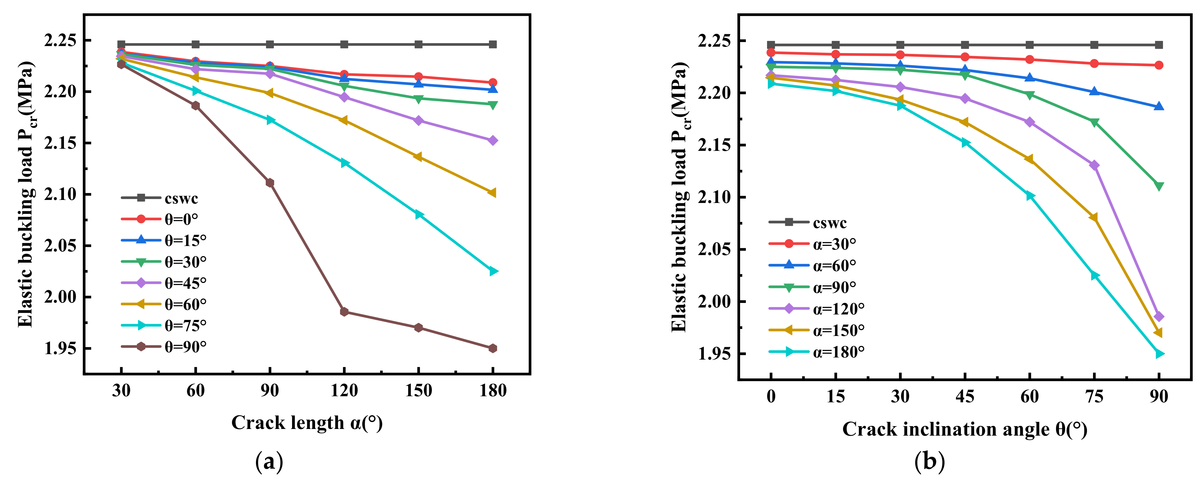
3.4. Influence of Crack Size on Elastic Buckling Load

The basic parameters of finite element models are R = 500 mm, L = 10,000 mm, T = 20 mm. In this subsection, the relationship between different crack lengths c (α = 30°, 60°, 90°, 120°, 150°, 180°) and different crack inclination angles (θ = 0°, 15°, 30°, 45°, 60°, 75°, 90°) is discussed. The elastic buckling load results of cracked cylindrical shells with simple supported at both ends are shown in Figure 8.
It can be seen from Figure 8a that the elastic buckling load of cylindrical shell without crack (cswc) is the highest, and the elastic buckling load decreases with the increase of crack length. The drop degree of elastic buckling load is the most significant when the crack inclination angle θ = 90°, and the elastic buckling load decreases slowly when the crack inclination angle θ = 0°. It can be seen from Figure 8b that the elastic buckling load of cylindrical shell without crack (cswc) is the highest, and the elastic buckling load decreases gradually with the increase of crack inclination angle. When the crack length is determined, the elastic buckling load is the maximum at θ = 0° and the elastic buckling load is the minimum at θ = 90°. The results show that the load bearing capacity of the cracked cylindrical shell is dropped by the increase of crack length and crack inclination angle at both ends of cylinder.

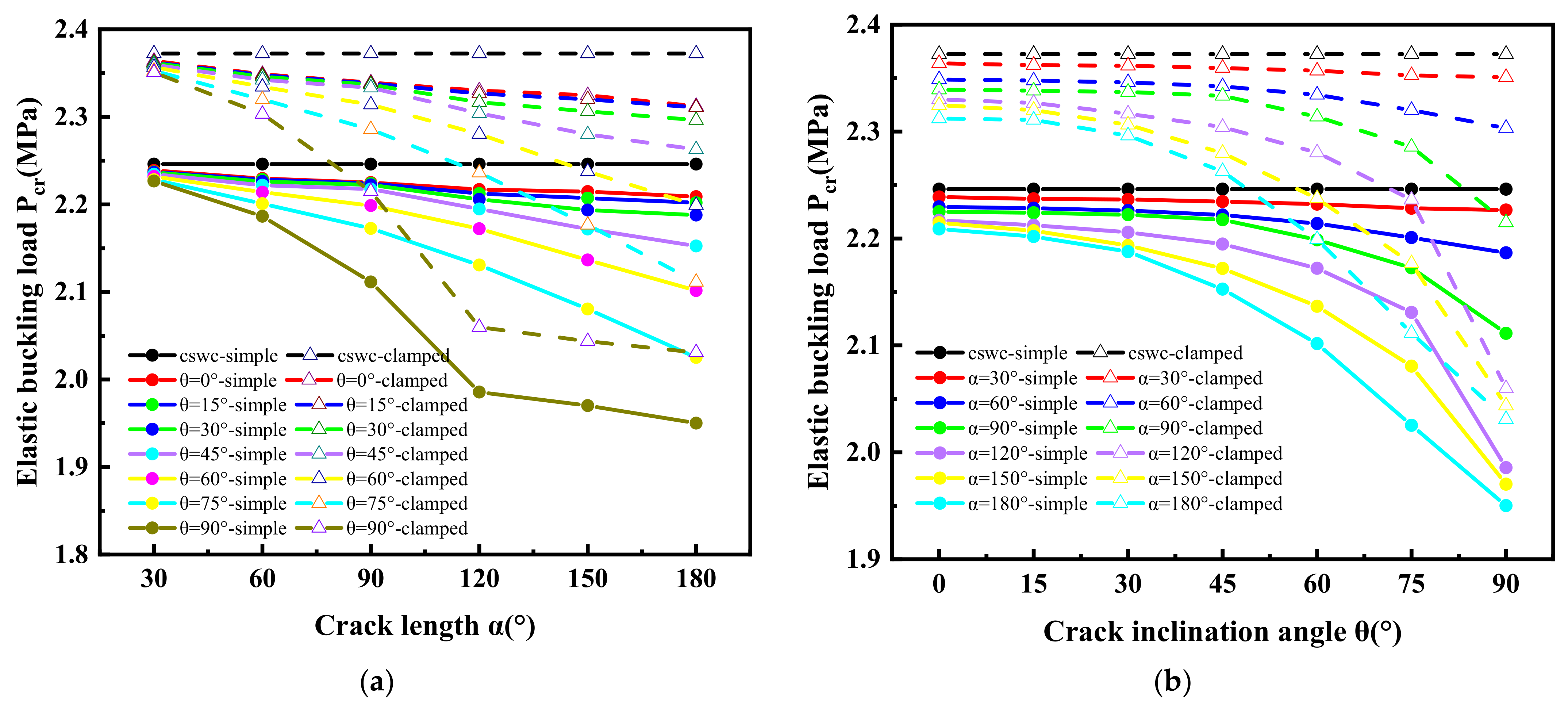
3.5. Influence of Clamped Support at Both Ends of Cylinder on Elastic Buckling Load

The basic parameters of finite element models are R = 500 mm, L = 10,000 mm, T = 20 mm. In this subsection, the relationship between different crack lengths c (α = 30°, 60°, 90°, 120°, 150°, 180°) and different crack inclination angles (θ = 0°, 15°, 30°, 45°, 60°, 75°, 90°) for different boundary conditions is discussed. The elastic buckling load results of cracked cylindrical shells with clamped supported at both ends of cylinder are shown in Figure 9.
It can be seen from Figure 9 that the elastic buckling load decreases gradually with the increase of crack length or crack inclination angle, and the drop degree of elastic buckling load becomes more significant with crack length and crack inclination angle for the cracked cylindrical shells with clamped supported at both ends of cylinder.
The elastic buckling load of the clamped support at both ends of cylinder is obviously higher than that of the simple support at both ends of cylinder, and the variation trends of elastic buckling load under two boundary conditions are similar.

4. Elastic-Plastic Buckling Behavior of Cracked Cylindrical Shells

The elastic buckling analysis only considers the elastic properties of material and does not consider the nonlinear conditions such as the elastoplastic constitutive relation of the material. Considering geometric nonlinearity and material nonlinearity in the calculation process of elastic-plastic buckling analysis, the pre-buckling and post-buckling behavior, and the elastic-plastic buckling load can be obtained. Therefore, elastic-plastic buckling analysis is used to obtain more accurate buckling load and behavior for elastic-plastic structures.
In order to compare, the selection of basic model parameters in this section is consistent with those in Section 3.

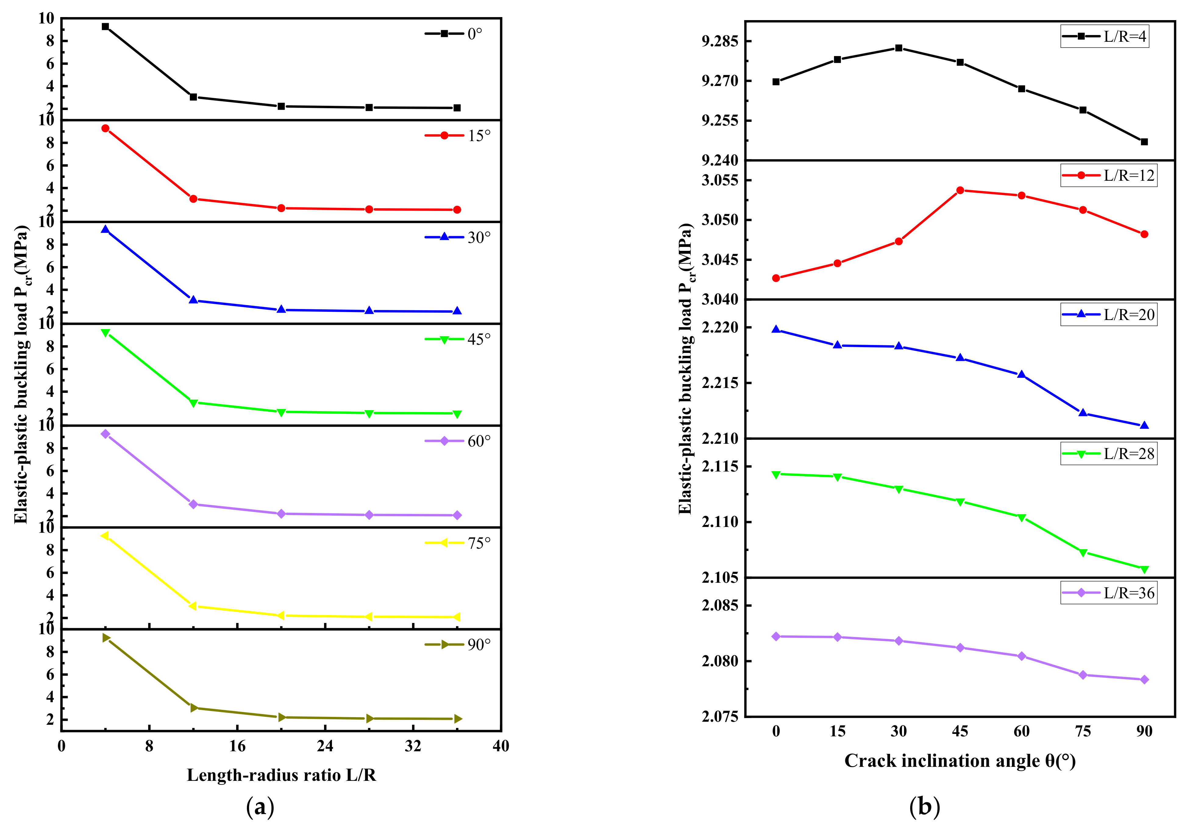
4.1. Influence of Length-Radius Ratio on Elastic-Plastic Buckling Load

It can be seen from Figure 10a that the elastic-plastic buckling load of L/R = 4 is obviously higher than that of other length-diameter ratios. The elastic-plastic buckling load decreases gradually with the increase of length-radius ratio of cylindrical shell. The variation of elastic-plastic buckling load is similar to that of elastic buckling load. It can be seen from Figure 10b that the elastic-plastic buckling load increases gradually with the crack inclination angle from 0° to 30° when L/R = 4, and the elastic-plastic buckling load reaches the maximum when θ = 30°. The elastic-plastic buckling load decreases gradually and varies slightly with the increase of crack inclination angle from 30° to 90°. The elastic-plastic buckling load increases gradually with the increase of crack inclination angle from 0° to 45° when L/R = 12, and the elastic-plastic buckling load reaches the maximum when θ = 45°. The elastic-plastic buckling load decreases gradually and varies slightly with the increase of crack inclination angle from 45° to 90°. The elastic-plastic buckling load decreases with the increase of crack inclination angle when L/R = 20, 28, 36. In addition, the elastic-plastic buckling load is less than the elastic buckling load. Similarly, the elastic-plastic buckling load is also affected by length-radius ratio and the boundary condition.

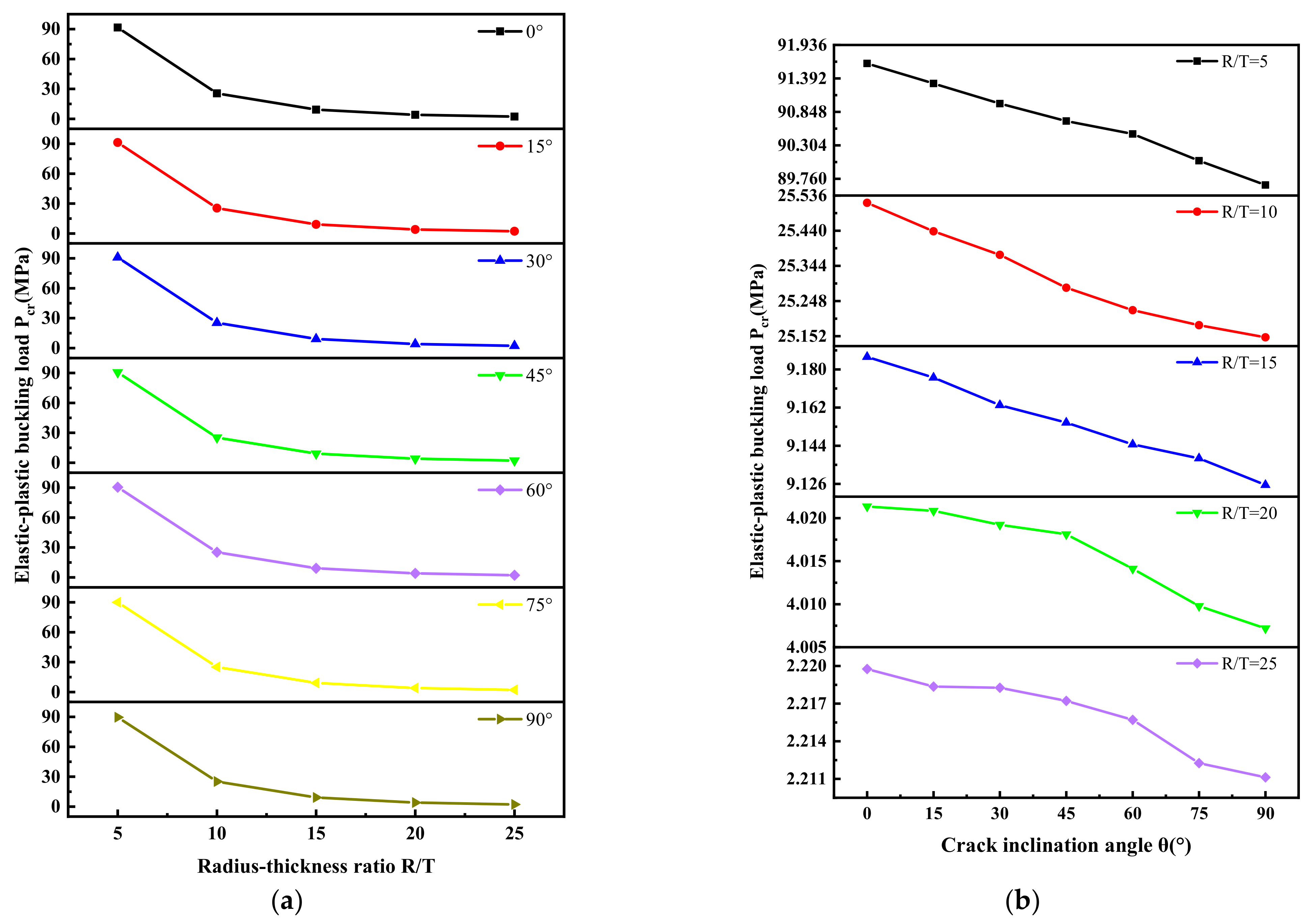
4.2. Influence of Radius-Thickness Ratio on Elastic-Plastic Buckling Load

It can be seen from Figure 11 that the elastic-plastic buckling load decreases with the increase of the radius-thickness ratio of the cylindrical shell and crack inclination angle. Compared with the elastic buckling load value (Figure 7b), there is little difference in the buckling load results between the elastic-plastic buckling analysis and the elastic buckling analysis when the radius-thickness ratio is larger (R/T = 25, namely thin cylindrical shell) where the elastic buckling load is 2.2387 MPa, and elastic-plastic load is 2.21976 MPa when θ = 0°. This is because the nonlinear effect of the initial geometric imperfections is affected by the thickness of shell. When the thickness of the cracked cylindrical shell is in a small range, the influence of the initial geometric imperfections can be ignored, and the elastic buckling load is close to elastic-plastic buckling load. The elastic-plastic buckling load is significantly smaller than that of elastic buckling load at a small radius-thickness ratio (R/T < 25). This is because with the increase of the thickness of cracked cylindrical shell, the nonlinear characteristics of the initial geometric defects gradually affect the geometric configuration of the cracked cylindrical shell in the deformation process, and the nonlinear characteristics of the elastoplastic constitutive model of the material affect the buckling behavior of the cracked cylindrical shell. The elastic-plastic buckling load could be calculated more accurately by using the elastic-plastic buckling analysis.
The results above show that the effects of material nonlinearity and geometric nonlinearity can not be ignored in elastic-plastic state, and the buckling loads of elastic-plastic structures can be obtained more accurately by elastic-plastic buckling analysis.

4.3. Influence of Crack Size on Elastic-Plastic Buckling Load

It can be seen from Figure 12 that the increase of crack length and crack inclination angle at both ends of cylinder weakens the bearing capacity of cracked cylindrical shell, and the variation of elastic-plastic buckling load is similar to that of elastic buckling load. In addition, compared with the elastic buckling load value in Figure 8, the elastic-plastic buckling load of the cracked cylindrical shell is evidently smaller than that of the elastic buckling load.

4.4. Influence of Clamped Support at Both Ends of Cylinder on Elastic-Plastic Buckling Load

It can be seen from Figure 13, similar to the results of elastic buckling analysis, the elastic-plastic buckling load decreases gradually with the increase of crack length or crack inclination angle, and the drop of elastic-plastic buckling load becomes more significant. In addition, the elastic-plastic buckling load of cracked cylindrical shells with clamped support at both ends of cylinder is higher than that with simple support at both ends of cylinder, while the two boundary conditions have similar buckling load variation trend.

4.5. Load-Displacement Curve under Elastic-Plastic Buckling

The basic parameters of the finite element models are R = 500 mm, L = 10,000 mm, T = 20 mm. Displacement load curves were plotted for different crack lengths c (α = 30°, 60°, 90°, 120°, 150°, 180°) and different crack inclination angles (θ = 0°, 15°, 30°, 45°, 60°, 75°, 90°) at simply supported boundary conditions. The variety of pre-buckling and post-buckling with cracked cylindrical shells with simple supported at both ends of cylinder are shown in Figure 14.
It can be seen from Figure 14 that the changes of crack inclination angle and crack length do not affect the variety of load-displacement about pre-buckling and post-buckling, but only affect the load bearing capacity of cracked cylindrical shells. In addition, the cracked cylindrical shell can still endure large deformation capacity in the post-buckling stage.

4.6. Analysis of Deformation under Elastic-Plastic Buckling

4.6.1. Analysis of Deformation of Cylindrical Shell under Elastic-Plastic Buckling

In this section, the equilibrium paths of the cylindrical shell model of L/R = 4, 28, R/T = 5, 25 are drawn under simple support, and the buckling deformation diagrams of cylindrical shells in three stages are given. The geometric parameters of the finite element models are shown in Table 1.
It can be seen from Figure 15 that in the initial stage of loading, the radial displacement of the shell increases linearly with the increase of the external pressure, corresponding to the path a, when the cylindrical shell is in the stage of elastic buckling. With the increase of the external pressure, the radial displacement increases rapidly, and enters the nonlinear buckling stage. The maximum load is the elastic-plastic buckling load, corresponding to the path b. With the continuous increase of the plastic deformation of the cylindrical shell, finally, the structure loses the ability to continue to bear load, the deformation of the cylindrical shell becomes larger, but the external pressure load decreases gradually, and enters the post-buckling stage, corresponding to the path c.
The load of the cylindrical shell increases gradually from path a to path b, the instability wave of the cylindrical shell begins to occur at path b. The overall instability of the structure occurs. At this time, the external load increases slightly, the instability wave expands rapidly, and the cylindrical shell collapses at path c in the post-buckling stage, and the cross section begins to ellipse in the form of dent. The whole buckling occurs in the short cylinder and the local buckling occurs in the long cylinder. Compared with models 1 and 3, it can be found that the cross section at the dent of the long cylinder closes and transfers along the axial direction of the cylindrical shell. With the increase of R/T, the transfer length is longer, that is, the buckling transfer region of the thick-walled long cylinder is shorter than that of the thin-walled long cylinder.

4.6.2. Analysis of Deformation of Cracked Cylindrical Shell under Elastic-Plastic Buckling

In order to compare with the cylindrical shell, the equilibrium paths of the cracked cylindrical shell model (θ = 45°) with the simple support are drawn respectively, and the buckling deformation diagrams of the cylindrical shell in three stages are given. The geometric parameters of the model are shown in Table 2.
Due to the existence of inclined through crack, the stress concentration is appeared at the crack tip, which leads to the decrease of load bearing capacity of the cracked cylindrical shell. Compared with Figure 16, it can be seen that the crack surface opens gradually in the process of buckling deformation with the increase of external pressure load. Model 1–45 and model 3–45, model 2–45 and model 4–45 show that the displacement of thick-walled cylinder is great and its collapse is serious in the post-buckling stage. Model 1–45 and model 2–45, model 3–45 and model 4–45 show that global buckling occurs in short cylinders, local buckling occurs in long cylinders, and crack do not affect the buckling modes.

5. Regression Analysis of Buckling Load of Cracked Cylindrical Shell

5.1. Regression Analysis of Elastic Buckling Load

In this section, the nonlinear regression is used to obtain the relationship between geometric parameters (length-radius ratio, radius-thickness ratio, crack length and crack inclination angle) and elastic buckling load. After comparing various fitting forms, the regression formula is finally chosen as shown in Equation (2).
P c r P t = f L R , R T , c , θ = a T x
where, Pcr is the buckling load of cylindrical shell with inclined through crack, Pt is the buckling load of cylindrical shell without crack, Pcr/Pt is the buckling load ratio of cylindrical shells with and without inclined through crack, a is the coefficient vector and T is the matrix transpose symbol and as following:
a = a 1 , a 2 , a 3 , a 4 , a 5 , a 6 , a 7 , a 8 , a 9 , a 10 , a 11 , a 12 , a 13 , a 14 , a 15 T x = 1 , L R , R T , c , θ , ( L R ) 2 , ( R T ) 2 , c 2 , θ 2 , L R R T , L R c , L R θ , R T c , R T θ , c θ
The elastic buckling load is obtained by finite element simulation, and the parameters of cracked cylindrical shell are shown in Table 3. The basic parameters of the cracked cylindrical shell with simple support at both ends are as follows: different length-radius ratios (L/R = 4, 12, 20, 28, 36) different radius-thickness ratios (R/T = 5, 10, 15, 20, 25) different crack length c (α = 30°, 60°, 90°, 120°, 150°, 180°) different crack inclination angle (θ = 0°, 15°, 30°, 45°, 60°, 75°, 90°). The basic parameters of the cracked cylindrical shells clamped support at both ends are as follows: the value of length-radius ratio is 20 and the value of radius-thickness ratio is 25, different crack lengths c(α = 30°, 60°, 90°, 120°, 150°, 180°), different crack inclination angles (θ = 0°, 15°, 30°, 45°, 60°, 75°, 90°).
The elastic buckling load is fitted by regression according to Equation (2).
The fitting results for cracked cylindrical shell with simple support are shown in Table 4, and the regression correlation coefficient R2 = 0.9425. The regression formula can approximately reflect the relationship between geometric parameters (length-radius ratio, radius-thickness ratio, crack length and crack inclination angle) and elastic buckling load, which can be used to predict the buckling load of cylindrical shell with inclined through crack.
Figure 17a shows the relationship between elastic buckling load, length-radius and crack inclination angle when R/T = 25, c (α = 30°), which reflects the regression relationship between elastic buckling load and length-radius ratio, crack inclination angle.
Figure 17b shows the relationship between elastic buckling load, radius-thickness ratio and crack inclination angle when L/R = 20, c (α = 30°), which reflects the regression relationship between elastic buckling load and radius-thickness ratio, crack inclination angle.
Figure 17c shows the relationship between elastic buckling load, crack length, and crack inclination angle when L/R = 20, R/T = 25, which reflects the regression relationship between elastic buckling load and crack length, crack inclination angle.
The fitting results for cracked cylindrical shell with clamped support are shown in Table 5. The regression fitting diagram is shown in Figure 18, and the regression correlation coefficient R2 = 0.92815. The regression formula can reflect the relationship between crack length, crack inclination angle and elastic buckling load for cracked cylindrical shell with clamped support (L/R = 20, R/T = 25).

5.2. Regression Analysis of Elastic-Plastic Buckling Load

The relationship between geometric parameters (length-radius ratio, radius-thickness ratio, crack length and crack inclination angle) and elastic-plastic buckling load are obtained by nonlinear regression. The regression formula is determined according to Equation (2). The parameters of cracked cylindrical shell are shown in Table 3.
The fitting results of cracked cylindrical shell with simple support are shown in Table 6, and the regression correlation coefficient R2 = 0.9503. The regression formula can approximately reflect the relationship between geometric parameters (length-radius ratio, radius-thickness ratio, crack length and crack inclination angle) and elastic-plastic buckling load, which can predict the buckling load of cylindrical shell with inclined through crack.
Consistent with Section 5.1, Figure 19 reflects the regression relationship between geometric parameter (length-radius ratio, radius-thickness ratio, crack length and crack inclination angle) and elastic-plastic buckling load.
The fitting results for cracked cylindrical shell with clamped support are shown in Table 7. The regression fitting diagram is shown in Figure 20, and the regression correlation coefficient R2 = 0.96076. The regression formula can reflect the relationship between geometric parameters (crack length and crack inclination angle) and elastic buckling load.

6. Conclusions

In this paper, the elastic buckling behavior and elastic-plastic buckling behavior of cylindrical shells with an inclined through crack under external pressure are studied by finite element method. The effects of crack length (c), crack inclination (θ), length- radius ratio (L/R), radius-thickness ratio (R/T), boundary conditions elastic buckling load and elastic-plastic buckling load of cracked cylindrical shell are analyzed and discussed. The main conclusions are as follows:
(1)
The analysis of cracked cylindrical shells with simple support on buckling load shows that the load bearing capacity of cracked cylindrical shells decreases with the increase of length- radius ratio. The elastic buckling load of short cylindrical shell increases gradually with the increase of crack inclination angle from 0° to 45°, and the elastic buckling load decreases gradually with the increase of crack inclination angle from 45°to 90°. The elastic buckling load of long cylindrical shell decreases gradually with the increase of crack inclination angle. The short cylindrical shell is greatly affected by the boundary conditions. For long cylindrical shells, the influence of boundary conditions on elastic buckling load is small or even negligible. In addition, the elastic-plastic buckling load is less than the elastic buckling load. Similarly, the elastic-plastic buckling load is also affected by length-radius ratio and the boundary condition.
(2)
The analysis of cracked cylindrical shells with simple support on buckling load shows that the load bearing capacity of cracked cylindrical shell is weaker with the increase of radius-thickness ratio and crack inclination angle. When the thickness of cylindrical shell is small, the difference between elastic and elastic-plastic buckling load is small. When the thickness of cylindrical shell is large, the influence of geometric nonlinearity and material nonlinearity is prominent, and the elastic-plastic buckling load is obviously smaller than that of elastic buckling load.
(3)
The analysis of cracked cylindrical shells with simple support on buckling load shows that the increase of crack length and crack inclination angle weakens the load capacity of cracked cylindrical shell. When the crack length is determined, the elastic buckling load is the maximum at θ = 0° and the elastic buckling load is the minimum at θ = 90°. The variation of elastic-plastic buckling load is consistent with that of elastic buckling load. Under the clamped support, the variation of buckling load is consistent with the buckling load of cracked cylindrical shell with simple support, and the buckling load of cracked cylindrical shell with clamped support is evidently higher than that of simple support. The post-buckling analysis further shows that the changes of crack inclination angle and crack length do not affect the variation modes of pre-buckling and post-buckling deformation of cracked cylindrical shells, but affect the load bearing capacity. In addition, the cracked cylindrical shell can still endure large deformation capacity during the post-buckling stage.
(4)
Based on the finite element solution of buckling load, the relations between the buckling load of different boundary condition (simple support, clamped support) and geometric parameters (length-radius ratio, radius-thickness ratio, crack length and crack inclination angle) are obtained by nonlinear regression which can predict the elastic and elastic-plastic buckling load of cylindrical shell with inclined through crack under external pressure.

Author Contributions

S.-C.L.: conception, methodology, software, writing—manuscript, and designed the research. Y.-C.Z.: software. L.C.: investigation. C.-Y.Z.: formal analysis, conception and funding acquisition. X.-H.H.: funding acquisition. All authors have read and agreed to the published version of the manuscript.

Funding

This paper was funded by National Natural Science Foundation of China (51975271).

Conflicts of Interest

The authors declare no conflict of interest.

References

  1. Zhou, Y.; Stanciulescu, I.; Eason, T.; Spottswood, M. Nonlinear elastic buckling and postbuckling analysis of cylindrical panels. Finite Elem. Anal. Des. 2015, 96, 41–50. [Google Scholar] [CrossRef] [Green Version]
  2. Blachut, J. Experimental Perspective on the Buckling of Pressure Vessel Components. Appl. Mech. Rev. 2014, 66, 010803. [Google Scholar] [CrossRef]
  3. Von Kármán, T.H. The Buckling of Spherical Shells by External Pressure. J. Aeronaut. Sci. 1939, 7, 43–50. [Google Scholar] [CrossRef]
  4. Stein, M. The Influence of Prebuckling Deformations and Stresses on the Buckling of Perfect Cylinders; NASA: Washington, DC, USA, 1964. [Google Scholar]
  5. Vodenitcharova, T.; Ansourian, P. Buckling of circular cylindrical shells subject to uniform lateral pressure. Eng. Struct. 1996, 18, 604–614. [Google Scholar] [CrossRef]
  6. Aghajari, S.; Abedi, K.; Showkati, H. Buckling and post-buckling behavior of thin-walled cylindrical steel shells with varying thickness subjected to uniform external pressure. Thin Walled Struct. 2006, 44, 904–909. [Google Scholar] [CrossRef]
  7. Papadakis, G. Buckling of thick cylindrical shells under external pressure: A new analytical expression for the critical load and comparison with elasticity solutions. Int. J. Solids Struct. 2008, 45, 5308–5321. [Google Scholar] [CrossRef] [Green Version]
  8. Taraghi, P.; Zirakian, T.; Karampour, H. Parametric study on buckling stability of CFRP-strengthened cylindrical shells subjected to uniform external pressure. Thin Walled Struct. 2021, 161, 107411. [Google Scholar] [CrossRef]
  9. Zhang, J.; Zhu, Z.; Wang, F.; Zhao, X.; Zhu, Y. Buckling behaviour of double-layer and single-layer stainless steel cylinders under external pressure. Thin Walled Struct. 2021, 161, 107485. [Google Scholar] [CrossRef]
  10. Xue, J. A non-linear finite-element analysis of buckle propagation in subsea corroded pipelines. Finite Elem. Anal. Des. 2006, 42, 1211–1219. [Google Scholar] [CrossRef]
  11. Ifayefunmi, O. Buckling behavior of axially compressed cylindrical shells: Comparison of theoretical and experimental data. Thin Walled Struct. 2016, 98, 558–564. [Google Scholar] [CrossRef]
  12. Badamchi, K.; Hossien, S. Experiments on buckling behavior of thin-walled steel pipes subjected to axial compression and external pressure. Thin Walled Struct. 2022, 174, 109122. [Google Scholar] [CrossRef]
  13. Frano, R.; Forasassi, G. Experimental evidence of imperfection influence on the buckling of thin cylindrical shell under uniform external pressure. Nucl. Eng. Des. 2009, 239, 193–200. [Google Scholar] [CrossRef]
  14. Fraldi, M.; Guarracino, F. An improved formulation for the assessment of the capacity load of circular rings and cylindrical shells under external pressure. Part 1. Analytical derivation. Thin Walled Struct. 2011, 49, 1054–1061. [Google Scholar] [CrossRef]
  15. De Paor, C.; Kelliher, D.; Cronin, K.; Wright, W.; McSweeney, S. Prediction of vacuum-induced buckling pressures of thin-walled cylinders. Thin Walled Struct. 2012, 55, 1–10. [Google Scholar] [CrossRef]
  16. Rathinam, N.; Prabu, B. Numerical study on influence of dent parameters on critical buckling pressure of thin cylindrical shell subjected to uniform lateral pressure. Thin Walled Struct. 2015, 88, 1–15. [Google Scholar] [CrossRef]
  17. Zhu, Y.; Dai, Y.; Ma, Q.; Tang, W. Buckling of externally pressurized cylindrical shell: A comparison of theoretical and experimental data. Thin Walled Struct. 2018, 129, 309–316. [Google Scholar] [CrossRef]
  18. Maali, M.; Kılıç, M.; Yaman, Z.; Ağcakoca, E.; Aydın, A.C. Buckling and post-buckling behavior of various dented cylindrical shells using CFRP strips subjected to uniform external pressure: Comparison of theoretical and experimental data. Thin Walled Struct. 2019, 137, 29–39. [Google Scholar] [CrossRef]
  19. Zhang, J.; Zhang, S.; Cui, W.; Zhao, X.; Tang, W.; Wang, F. Buckling of circumferentially corrugated cylindrical shells under uniform external pressure. Ships Offshore Struct. 2019, 14, 879–889. [Google Scholar] [CrossRef]
  20. Zhang, Y.; Huang, H.; Han, Q. Buckling of elastoplastic functionally graded cylindrical shells under combined compression and pressure. Compos. Part B Eng. 2015, 69, 120–126. [Google Scholar] [CrossRef]
  21. Heo, J.; Yang, Z.; Xia, W.; Oterkus, S.; Oterkus, E. Buckling analysis of cracked plates using peridynamics. Ocean. Eng. 2020, 214, 107817. [Google Scholar] [CrossRef]
  22. Yin, Q.; He, X.; Zhou, C. Study on Elastic Buckling Behavior of the Thin Plate with Mixed Mode I-Ii Crack. In Proceedings of the International Symposium on Structural Integrity, Hangzhou, China, 8–11 October 2021. [Google Scholar]
  23. Saemi, J.; Sedighi, M.; Shariati, M. Numerical and experimental study on buckling and postbuckling behavior of cracked cylindrical shells. Mech. Solids 2015, 50, 529–545. [Google Scholar] [CrossRef]
  24. Allahbakhsh, H.; Shariati, M. Instability of cracked CFRP composite cylindrical shells under combined loading. Thin Walled Struct. 2014, 74, 28–35. [Google Scholar] [CrossRef]
Figure 1. Diagram of a cracked cylindrical shell.
Metals 13 00174 g001
Figure 2. Determination of crack angle in finite element model. (a) Circumferential crack section (θ = 0°) (b) Inclined crack section (θ ≠ 0°).
Metals 13 00174 g002
Figure 3. (a) Finite element model with clamped on both ends; (b) Finite element mesh.
Metals 13 00174 g003
Figure 4. Buckling modes for modle 1~4 (Simple support) (a) Model 1; (b) Model 2; (c) Model 3; (d) Model 4.
Metals 13 00174 g004
Figure 5. Buckling modes for modle 5~8 (Clamped support) (a) Model 5; (b) Model 6; (c) Model 7; (d) Model 8.
Metals 13 00174 g005
Figure 6. Relation between length-radius ratio and elastic buckling load (a) Different length-radius ratios; (b) Different crack inclination angles.
Metals 13 00174 g006
Figure 7. Relation between radius-thickness ratio and elastic buckling load (a) Different radius-thickness ratios; (b) Different crack inclination angles.
Metals 13 00174 g007
Figure 8. Relation between crack length and elastic buckling load with simple support at both ends of cylinder (a) Different crack lengths; (b) Different crack inclination angles.
Metals 13 00174 g008
Figure 9. Relation between crack length and elastic buckling load with clamped support at both ends of cylinder (a) Different crack lengths; (b) Different crack inclination angles.
Metals 13 00174 g009
Figure 10. Relation between length-radius ratio and elastic-plastic buckling load (a) Different length-radius ratios; (b) Different crack inclination angles.
Metals 13 00174 g010
Figure 11. Relation between radius-thickness ratio and elastic-plastic buckling load (a) Different radius-thickness ratios; (b) Different crack inclination angles.
Metals 13 00174 g011
Figure 12. Relation between crack length and elastic-plastic buckling load with simple support at both ends of cylinder (a) Different crack lengths; (b) Different crack inclination angles.
Metals 13 00174 g012
Figure 13. Relation between crack length and elastic-plastic buckling load with clamped support at both ends of cylinder (a) Different crack lengths; (b) Different crack inclination angles.
Metals 13 00174 g013
Figure 14. Load-displacement curves (a) Different crack inclination angles (α = 90°); (b) Different crack lengths (θ = 45°).
Metals 13 00174 g014
Figure 15. Buckling deformation diagrams of model 1~4 (a) Model 1; (b) Model 2; (c) Model 3; (d) Model 4.
Metals 13 00174 g015aMetals 13 00174 g015b
Figure 16. Buckling deformation diagrams of model 1–45~4–45(characteristics path) (a) Model 1–45; (b) Model 2–45; (c) Model 3–45; (d) Model 4–45.
Metals 13 00174 g016aMetals 13 00174 g016b
Figure 17. Relation of elastic buckling of cracked cylindrical shell with simple support (a) Different length-radius ratios and crack inclination angles; (b) Different radius-thickness ratios and crack inclination angles; (c) Different crack lengths and crack inclination angles.
Metals 13 00174 g017aMetals 13 00174 g017b
Figure 18. Relation of elastic buckling of cracked cylindrical shell with clamped support (L/R = 20, R/T = 25).
Metals 13 00174 g018
Figure 19. Relation of elastic-plastic buckling of cracked cylindrical shell with simple support (a) Different length-radius ratios and crack inclination angles; (b) Different radius-thickness ratios and crack inclination angles; (c) Different crack lengths and crack inclination angles.
Metals 13 00174 g019
Figure 20. Relation of elastic-plastic buckling of cracked cylindrical shell with clamped support (L/R = 20, R/T = 25).
Metals 13 00174 g020
Table 1. The Parameters of models (θ = 45°).
Model
Numbering
Boundary
Condition
Cylinder
Characteristics
Outer Diameter Do/mmWall Thickness T/mmLength L/mm
1Simple supportThin-walled
long cylinder
10002014,000
2Thin-walled short cylinder1000202000
3Thick-walled long cylinder100010014,000
4Thick-walled short cylinder10001002000
5Clamped supportThin-walled
long cylinder
10002014,000
6Thin-walled short cylinder1000202000
7Thick-walled long cylinder10010014,000
8Thick-walled short cylinder1001002000
Table 2. The Parameter of Model.
Model NumberingCrack Inclination AngleBoundary ConditionCylinder Characteristics
1–4545°Simple supportThin-walled
long cylinder
2–4545°Thin-walled short cylinder
3–4545°Thick-walled long cylinder
4–4545°Thick-walled short cylinder
Table 3. Parameters for cracked cylindrical shell.
Boundary
Condition
Length-Radius
Ratio L/R
Radius-Thickness
Ratio R/T
Crack Length αCrack Inclination Angles θ
Simple
support
4, 12, 20, 28, 365, 10, 15, 20, 2530°, 60°, 90°, 120°, 150°, 180°0, 15°, 30°, 45°, 60°, 75°, 90°
clamped
support
2025
Table 4. Regression coefficients for cracked cylindrical shell with simple support.
a1, a2, a3, a6, a7, a8, a9, a12, a14, a15a4a5a10a11a13R2εmax (%)
00.06670.00060.002−0.0017−0.00130.942510.9
Note: ε m a x = max P c r P t F E M P c r P t R e g P c r P t F E M × 100 % ,   P c r P t F E M represents the finite element simulation results of P c r P t , P c r P t R e g indicates the regression result of P c r P t .
Table 5. Regression coefficients for cracked cylindrical shell with clamped support (L/R = 20, R/T = 25).
a2, a3 a6, a7, a10, a11,
a12, a13, a14
a1a4a5a8a9a15R2εmax (%)
00.98147−8.93925−70.001436.91771−8−1.29149−5−9.45979−60.928152
Note: ε m a x = max P c r P t F E M P c r P t R e g P c r P t F E M × 100 % .
Table 6. Regression coefficients for cracked cylindrical shell with simple support.
a1, a2, a3, a6, a8, a9, a12, a14, a15a4a5a7a10a11a13R2εmax (%)
00.06060.00070.00030.0016−0.0014−0.00130.950311.5
Note: ε m a x = max P c r P t F E M P c r P t R e g P c r P t F E M × 100 % .
Table 7. Regression formula coefficients for cracked cylindrical shell with Clamped on both ends (L/R = 20, R/T = 25).
a2, a3 a6, a7, a10, a11, a12,
a13, a14
a1a4a5a8a9a15R2εmax %
00.96735.41031−40.00218−3.22613−6−1.83903−5−1.96793−60.960762.7
Note: ε m a x = max P c r P t F E M P c r P t R e g P c r P t F E M × 100 % .
Disclaimer/Publisher’s Note: The statements, opinions and data contained in all publications are solely those of the individual author(s) and contributor(s) and not of MDPI and/or the editor(s). MDPI and/or the editor(s) disclaim responsibility for any injury to people or property resulting from any ideas, methods, instructions or products referred to in the content.

