Article

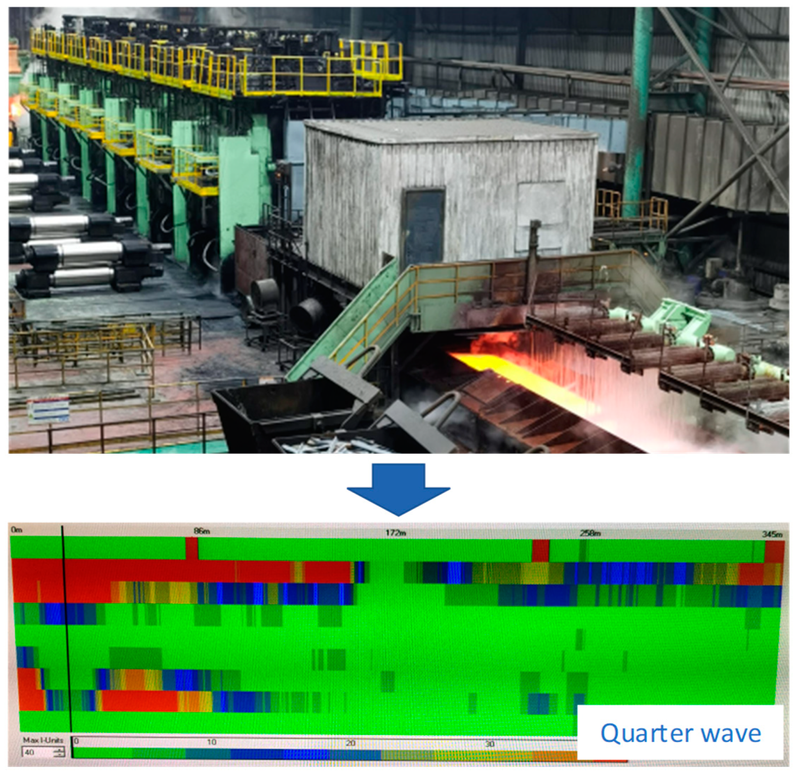
Research on Roll Shape Design for Quarter Wave Control of High-Strength Steel

1
National Engineering Technology Research Center of Flat Rolling Equipment, University of Science and Technology, Beijing 100083, China
2
2250 Hot Strip Mill, Baotou Steel Union Co., Ltd., Baotou 014010, China
3
CFHI Dalian Engineering & Technology Co., Ltd., Dalian 116600, China
*
Author to whom correspondence should be addressed.
Metals 2023, 13(1), 161; https://doi.org/10.3390/met13010161
Submission received: 1 December 2022 / Revised: 7 January 2023 / Accepted: 10 January 2023 / Published: 12 January 2023

Abstract

:
Quarter wave defects often occur in high-strength steel production in wide rolling mills, which seriously affect product quality and production stability. The existing shape control actuators, such as roll bending, roll shifting, and CVC roll shape, can not adjust the high-order wave, and the upgraded CVCplus roll shape also has limited effects on the quarter wave. Therefore, the MVCplus roll shape is developed based on the superposition principle in order to realize the local roll shape modification at the wave position. Two cosine curves are superposed on the CVC roll shape within the strip width to decrease the reduction at the quarter of the strip width, and maximum reduction is achieved at the position of maximum wave height. The new roll shape can significantly reduce the quarter wave defects in practical application, and has little effect on the adjustment characteristics of the original CVC roll shape.

1. Introduction

In the current climate of serious excess steel production capacity, many steel enterprises aim to comply with the future development trends of the steel industry, such as energy saving and lightweight production [1,2,3,4,5]. These companies have made great efforts to develop high-strength steel products and have spent a lot of money building special production lines for high-strength steel. High-strength steel is highly sought after in today’s market [6,7,8,9,10]. However, with the sharp increase in demand for high-strength strip materials, the market competition is becoming increasingly fierce. Users have put forward higher requirements for the quality of high-strength products, especially with regards to the strip shape, an important dimensional accuracy index [11,12,13].
Different from plain carbon steel, the significant increase in the strength of high-strength steel can lead to a series of flatness problems [14,15,16,17,18,19]. In particular, the high-strength strip frequently appears in high-order wave defects of quarter waves at the exit of the finishing mill as shown in Figure 1. It can be seen that the wave defects occur at approximately the quarter of the width direction of the strip, which is different from common, low-order wave defects in center buckle and edge waves. In actual production, high-strength steel is more prone to quarter wave defects than plain carbon steel. On the one hand, the high strength of the strip leads to larger roll force and high-order roll deflection. On the other hand, the high-strength steel always has a higher rolling temperature and a larger thermal crown, which makes the roll gap contour more complex after superposing it with the grinding roll shape. Meanwhile, the thin strip is more prone to quarter wave defects than thick plate, because the buckling critical value of a thin strip is smaller. The optimization of model parameters makes it difficult to eliminate this kind of defect, which directly affects the stability of hot rolling production and seriously restricts the improvement of production efficiency. Moreover, because the traditional hot rolling leveling process has limited ability to improve the flatness of high-strength strips, the shape quality of the downstream process also deteriorates. It can be seen that the high-order wave of hot rolled high-strength steel has become an urgent problem that many manufacturers need to solve.
Although the finishing mill is equipped with roll bending and roll shifting, it can only be used to control the low-order shape defects, such as center buckle and edge waves [20,21,22]. The high-order shape defects need to be eliminated in other ways, such as advanced roll shape, which is the most direct, the most flexible, and the most effective shape control method [23,24]. Since the production of high-strength steel faces great changes in material strength and specifications, the continuous variable crown (CVC) roll shape with a cubic curve is usually adopted on the finishing mill stand [25]. The continuous change and free selection of the roll gap crown are then realized by roll shifting [26,27,28]. The curve of CVC roll shape is shown in Figure 2, which shows the shape of the CVC roll and the assembly of a pair of CVC work rolls during operation.
For the upper surface of the top work roll body, the radius curve function is shown in Equation (1):
y t 0 ( x ) = R 0 + a 1 x + a 2 x 2 + a 3 x 3
where R0 represents the radius of the starting point of the roll body, x is the coordinates along the roll body, and a1, a2, a3 are coefficients of cubic polynomials.
When the axial moving distance of the roller is s (the direction shown in Figure 2 is positive), the function of the top roll curve is:
y t s ( x ) = y t 0 ( x s )
According to the anti-symmetry of the top and bottom CVC work roll, the function of the bottom roll curve is:
y b 0 ( x ) = y t 0 ( L x )
y b s ( x ) = y b 0 ( x + s ) = y t 0 ( L x s )
Therefore, the roll gap contour can be expressed as follows:
g ( x ) = D + H y t s ( x ) y b s ( x )
where D is the sum of the radius of the top roll and bottom roll and H is the rolling gap.
The quadratic gap crown Cq along the roll body is:
C q ( s ) = g ( L 2 ) g ( 0 )
When rolling the strip of width B, the effective quartic crown Ch within the strip width range is:
C h ( s ) = g ( L 2 B 4 ) 3 4 g ( L 2 ) 1 4 g ( L B 2 )
Due to the characteristics of anti-symmetry, no matter what the roll shifting position is, the roll gap contour between the top work roll and bottom work roll of CVC is always a parabola (as can be proven by the derivation of Formula (5)), which does not have the adjustment ability of high-order waves for strips. A seemingly effective approach is to upgrade CVC of cubic polynomial to enrich the function of the roll shape [30]. As a well-known enterprise in shape control, the SMS group was the first to develop the continuous variable crown plus (CVCplus) roll shape of quintic polynomials [31]. CVCplus is claimed to have the control ability of high-order waves. Many scholars have deduced and proven it theoretically [29]. However, from the practical application results, it cannot effectively eliminate the high-order wave, and it also affects the adjustment characteristics of the quadratic gap crown. This is the reason why most steel enterprises still use the CVC roll shape and the quarter wave defects are still frequent.

2. Deficiency of CVCplus in Controlling the Quarter Wave

In order to put forward a better method of roll shape design, we need to analyze the deficiency of CVCplus in solving quarter wave defects. Its curve function is shown as follows:
y t 0 ( x ) = R 0 + a 1 x + a 2 x 2 + a 3 x 3 + a 4 x 4 + a 5 x 5
where a1~a5 are coefficients of quintic polynomials.
It is assumed that when the axial movement of the top work rolls are, respectively, negative limit −sm and positive limit sm, the quadratic gap crowns are, respectively, Cq1 and Cq2, and the effective quartic crowns are, respectively, Ch1 and Ch2. Meanwhile, it is necessary to ensure that the two ends of the given strip width B have the same roll diameter to reduce the diameter difference. For the purpose of eliminating the high-order wave, B is the width of the strip where the quarter wave often occurs. The polynomial coefficients are determined by the above conditions. The derivation process of Cq(s) and Ch(s) can be referred to Equations (2)–(7).
C q ( s m ) = C q 1
C q ( s m ) = C q 2
C h ( s m ) = C h 1
C h ( s m ) = C h 2
y t 0 ( L / 2 B / 2 ) = y t 0 ( L / 2 + B / 2 )
The ideal result of roll shape design is not to affect the adjustment characteristics of the original CVC on the quadratic gap crown as far as possible. At the same time, it is better to have the same adjustment effect on the effective quadric crown in different roll shifting positions, so that Ch1 = Ch2. By derivation, a5 = 0, that is, yt0(x) becomes a quartic polynomial.
Take the 2250 mm hot rolling mill as an example; the body length of the work roll L is 2550 mm and the positive limit of roll shifting sm is 150 mm. The aim thickness of the rolled strip is 2.0~5.0 mm. The width of the strip with frequent quarter wave defects is 1600 mm. The adjustment range of the quadratic gap crown is between −0.5 mm and 0.5 mm, and the effective quartic crown is 0.04 mm. The obtained CVCplus curve is shown in Figure 3.
As can be seen from Figure 4, the effective quartic crown keeps constant with the change in the roll shifting position using CVCplus, and the change in the quadratic gap crown with roll shifting is no longer linear. This will affect the control accuracy of crowns, the center buckle, and edge waves. It can be seen from Figure 5 that the roll gap contour of CVCplus is very different from that of CVC at the same roll shifting position, and even has an opposite trend.
In addition, although the effective quartic crown of CVCplus is a constant value, it does not achieve the goal of “local modification”. The gap compensation effect can be checked by subtracting the roll gap contour of CVCplus and CVC. It can be seen from Figure 6 that the compensation from the middle to the edge of the strip is monotonously increasing, reaching the maximum at the strip edge. This means that although the reduction is made at the quarter of the strip width, the roll gap at the strip edge will get greater “lifting” which will lead to problems such as a smaller strip crown, edge thickening, etc., and it is easy to cause edge waves or edge stiffening in the downstream cold rolling process. In fact, this is an inherent geometric deficiency of the quintic polynomial, and it is impossible to achieve the maximum compensation at the position where the quarter wave height of the strip is the largest. Therefore, it is necessary to propose a new roll shape design method to achieve more accurate and local compensation.

3. MVCplus Roll Shape Design

The mixed variable crown plus (MVCplus) roll shape is designed adopting the method of curve superposition. Two cosine curves are superposed on the CVC within the left half width of the strip. The intersection of the two cosine curves is the maximum position of the left quarter wave height, as shown in Figure 7. The cosine curve is selected because it can ensure the smooth connection of curves in different regions. The reason why two cosine curves are selected is to adjust the maximum compensation position flexibly according to the wave position, because the quarter wave sometimes does not occur at the strict quarter of the strip width. The curve of MVCplus after superposition is shown in Figure 8.
y t ( x ) = y t 0 ( x ) + y t 1 ( x )
y t 1 ( x ) = { 0 0 x < L / 2 B / 2 A 2 cos ( w 1 x + f 1 ) + A 2 L / 2 B / 2 x < L / 2 m A 2 cos ( w 2 x + f 2 ) + A 2 L / 2 m x L / 2
y t 1 ( x ) = y t 1 ( L x )             L / 2 x L
w 1 = 2 π / ( B 2 m )
f 1 = π - π ( L B ) / ( B 2 m )
w 2 = π / m
f 2 = π - π L / m / 2
where yt1(x) is the compensation curve; x is the length coordinate of the roll barrel; A is the maximum value of radius compensation; w1 and f1 are, respectively, the angular velocity and phase of the cosine curve at the strip edge, and w2 and f2 are, respectively, the angular velocity and phase of the cosine curve in the middle of the strip. m refers to the distance between the center of the quarter wave and the middle of the strip, L refers to the length of the work roll barrel, and B refers to the strip width where the quarter wave often occurs.

4. Analysis of Adjusting Characteristics of MVCplus

It can be seen from Figure 9 that compared with the quadratic gap crown control capability of CVC, the adjustment of MVCplus to the quadratic crown is almost linear, especially in the range of ±100 mm, where roll shifting occurs more frequently, it is almost consistent with CVC (roll shifting distribution generally meets the normal distribution). Although the effective quartic crown is not a constant value, it is all positive, which indicates that it has the ability to reduce the quarter wave at different roll shifting positions.
It can be seen from Figure 10 that at the same roll shifting position, the roll gap contour of MVCplus is the partial correction of the CVC roll gap contour near the quarter of the strip width, and the overall trend is unchanged, which is superior to the CVCplus.
The gap compensation effect can be checked by subtracting the roll gap contour of MVCplus and CVC. It can be seen from Figure 11 that the maximum compensation is located at the position of the maximum quarter wave height, which is in line with the expected effect. MVCplus has little influence on the middle and edge of the base CVC roll shape, and only local corrections are made around the quarter position of the strip, so as to minimize the influence on the profile and flatness of the middle and edge of the strip.
Compared with CVC, MVCplus has no significant change in the ability to adjust the quadratic gap crown for strips with different widths, as shown in Figure 12, which means MVCplus has better retention in the quadratic crown control of the roll gap.
As shown in Figure 13, MVCplus has the largest ability to adjust the effective quartic crown for a 1600 mm strip. For a strip that is narrower or wider than 1600 mm, the amount of ability decline is acceptable, so it can also eliminate the quarter wave for these widths of strip.
As shown in Figure 14, the effective quartic crown changes parabola with the work roll shifting. When the roll shifting is zero, the adjustment ability of the effective quartic crown reaches the maximum, and the adjustment ability gradually decreases when the work roll moves toward the positive limit or negative limit. Although the ideal effect of “the effective quartic crown keeps a constant value with the change in the roll shifting” is not achieved, this is an acceptable result, because the roll shifting distribution often presents a normal distribution form. The use frequency near zero position of the roll shifting is the highest, and the compensation effect can be optimal at this position.

5. Application Effect

In order to compare the application effect before and after using the MVCplus roll shape, the intelligent identification and statistics system for wave defects was firstly developed, which has been applied online in a 2250 mm hot rolling production line mainly producing high-strength steel. Its working principle is to collect the flatness value of each channel detected by the flatness gauge (generally nine channels), and judge the wave location by comparing the channel values distributed on each cross-section to determine which kind of wave defect it is. Through this system, the wave types of different steel grades and specifications are known, and the amplitude and length of the wave are also obtained, which is helpful to accurately design the roll shape.
Based on the statistics of the developed system, after using the MVCplus roll shape, the high order wave shape has been significantly improved, and the incidence rate of quater wave has decreased from 63.9% to 8.5%. At the same time, the crown and other indicators are not affected, and good application results have been achieved.

6. Conclusions

(1)
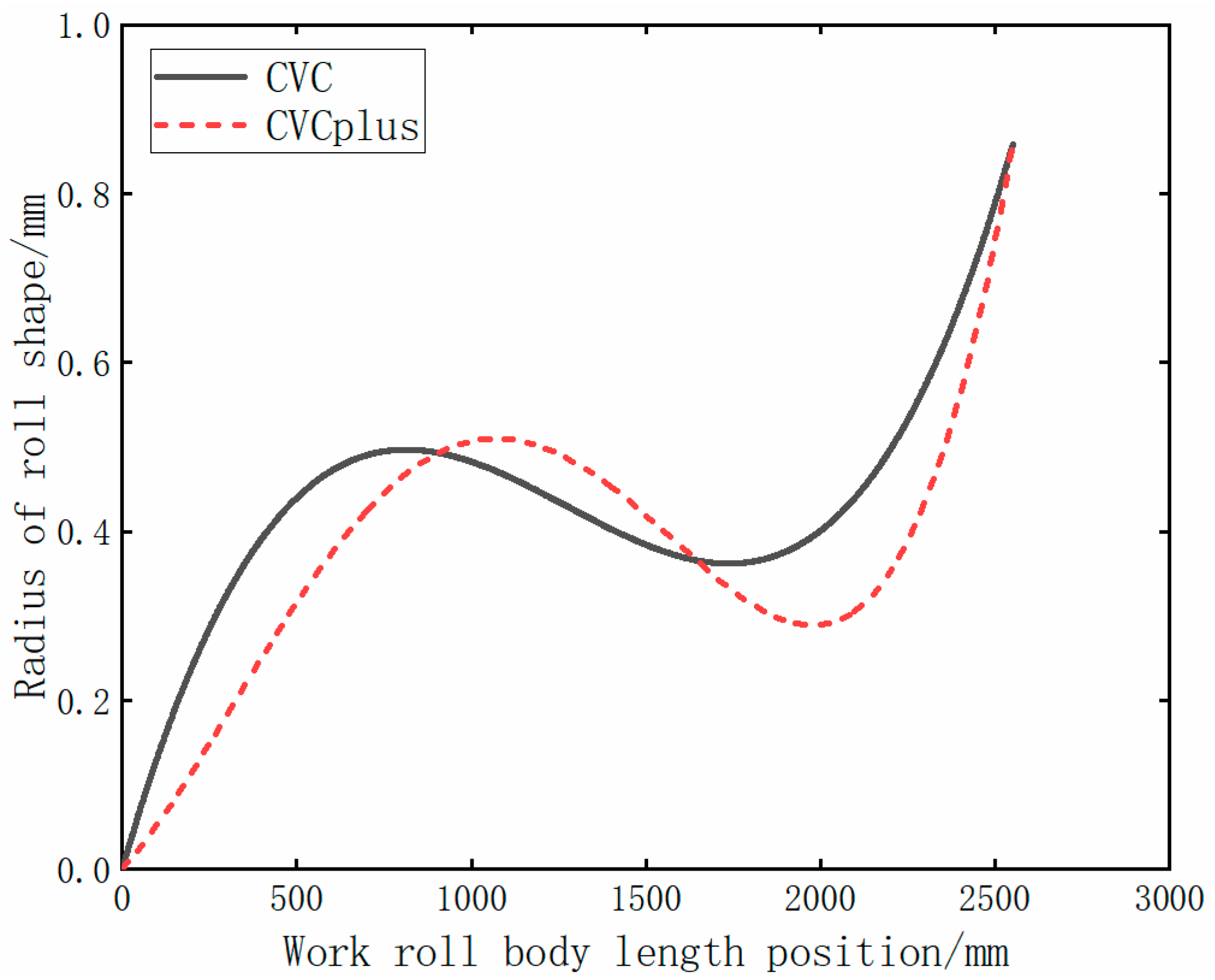
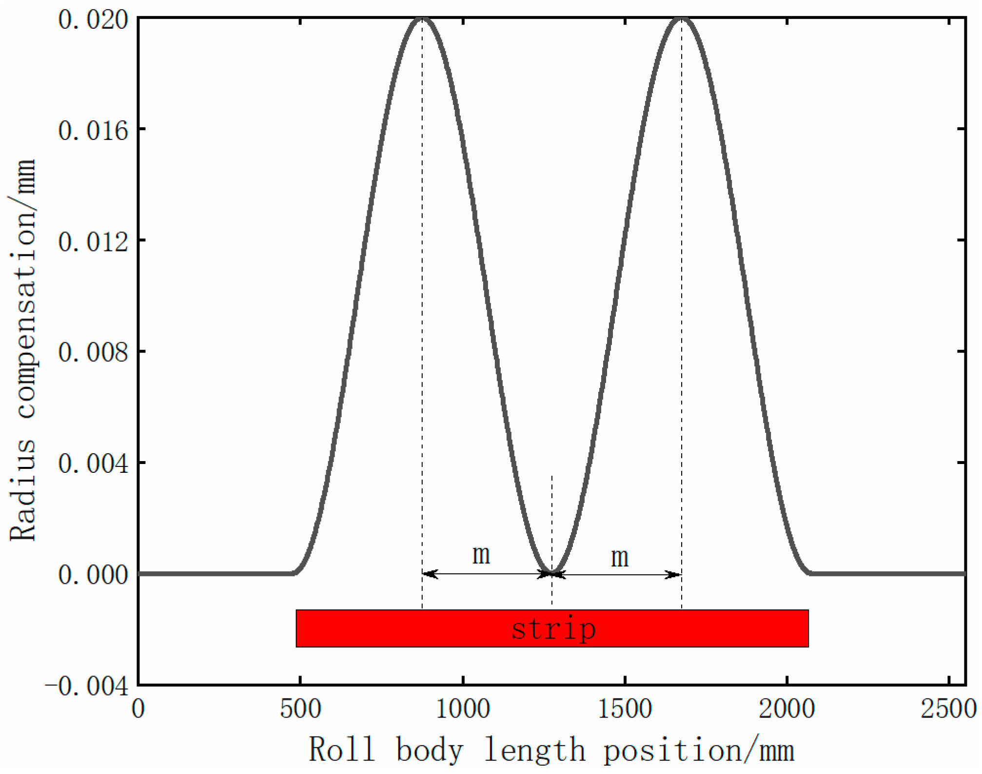
By analyzing the shortcomings of CVCplus in controlling the quarter wave, the MVCplus roll shape is designed using the superposition principle to superpose the cosine curve on the traditional CVC roll shape.
(2)
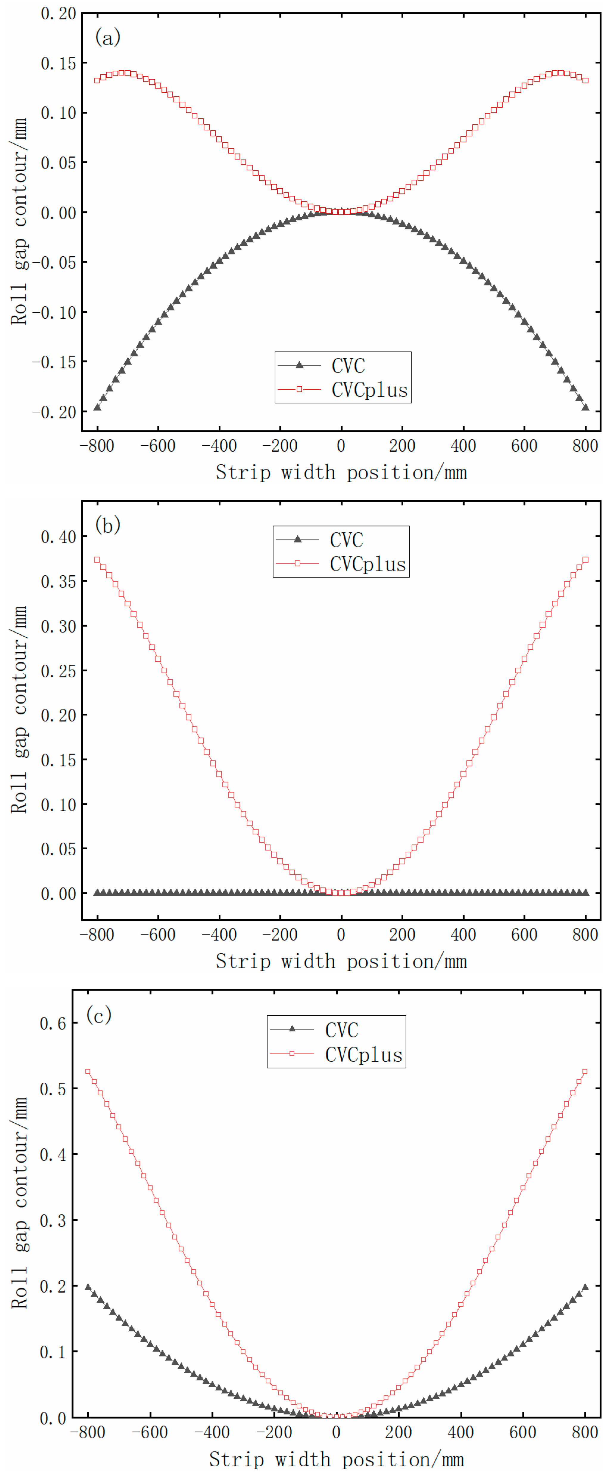
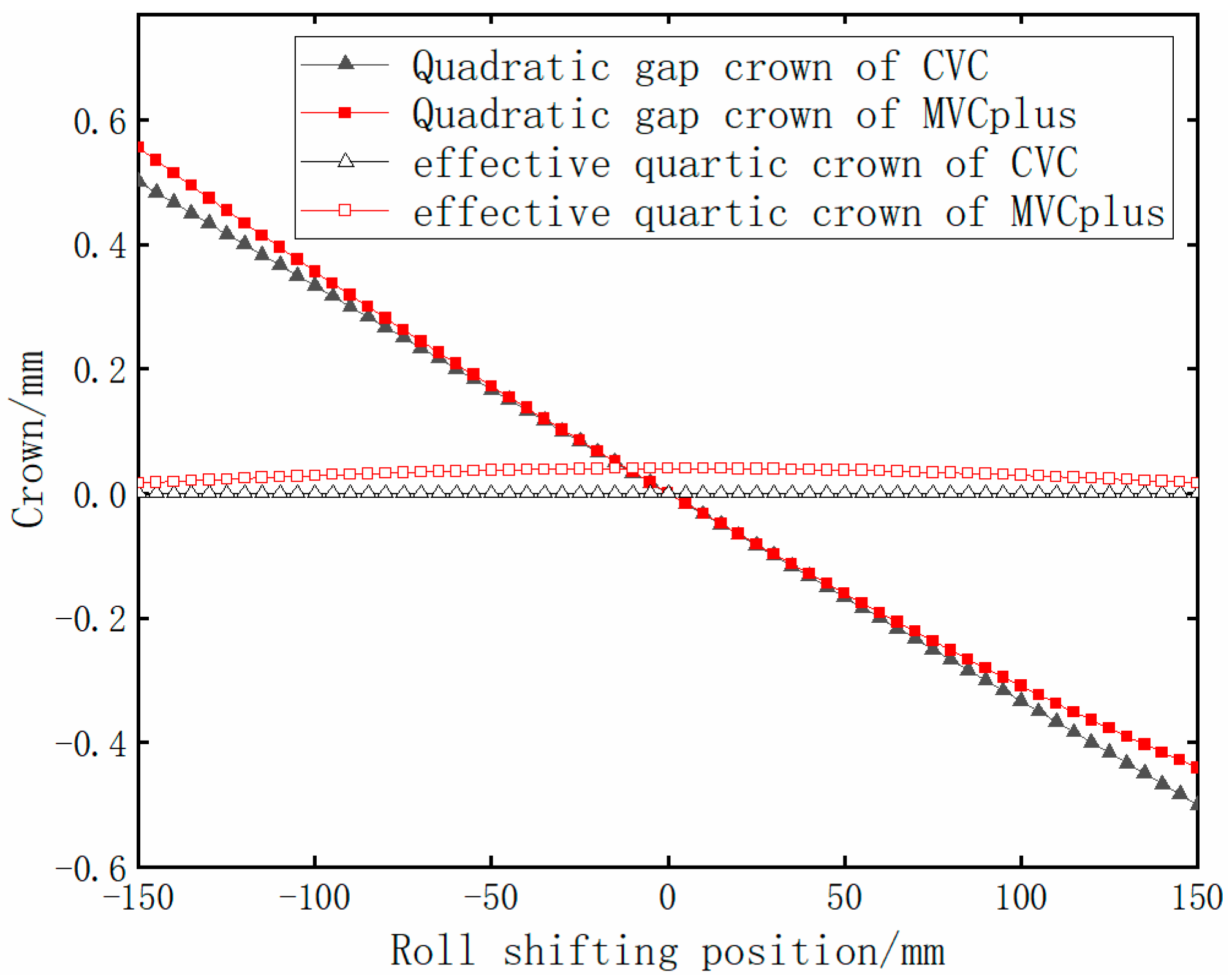
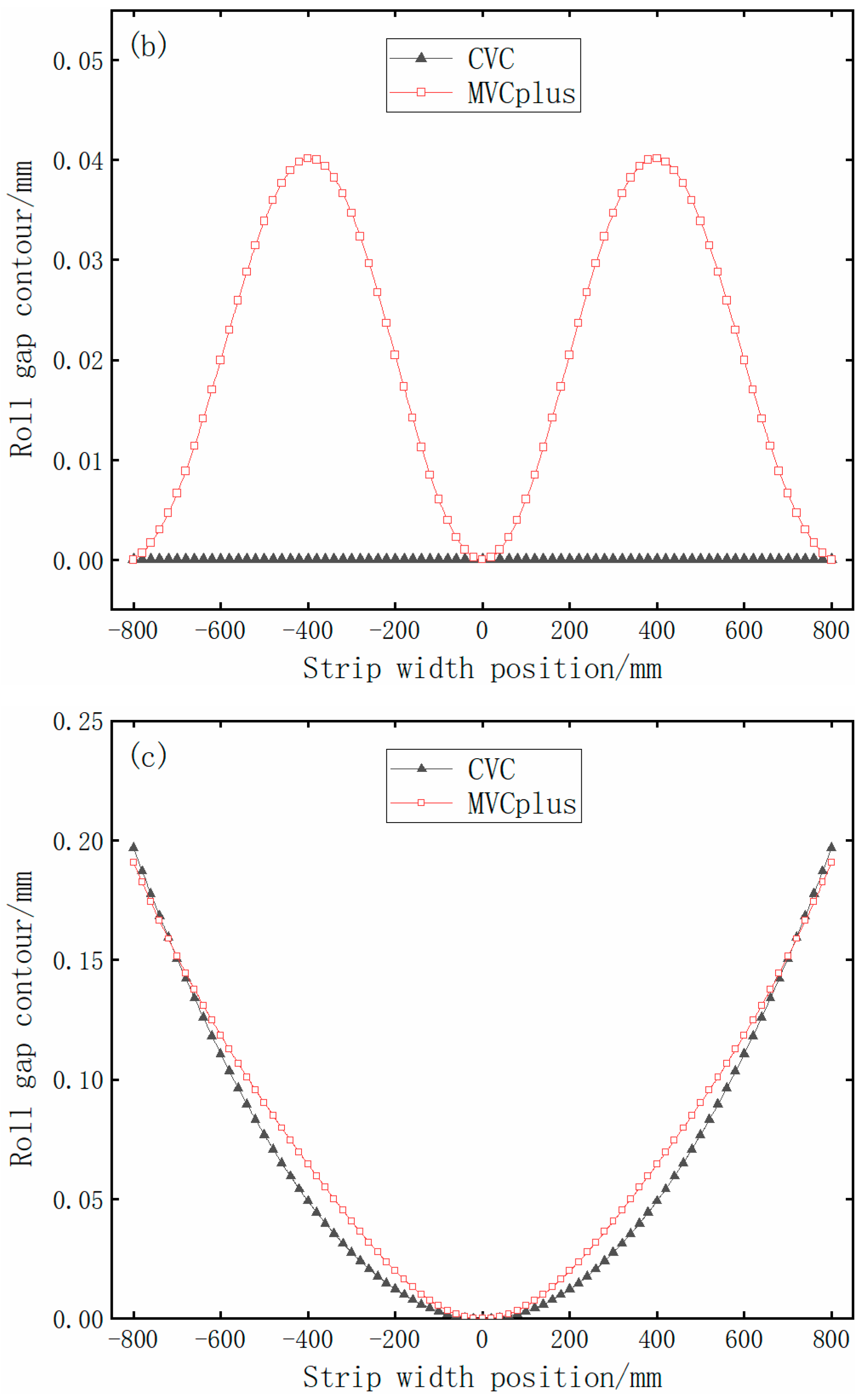
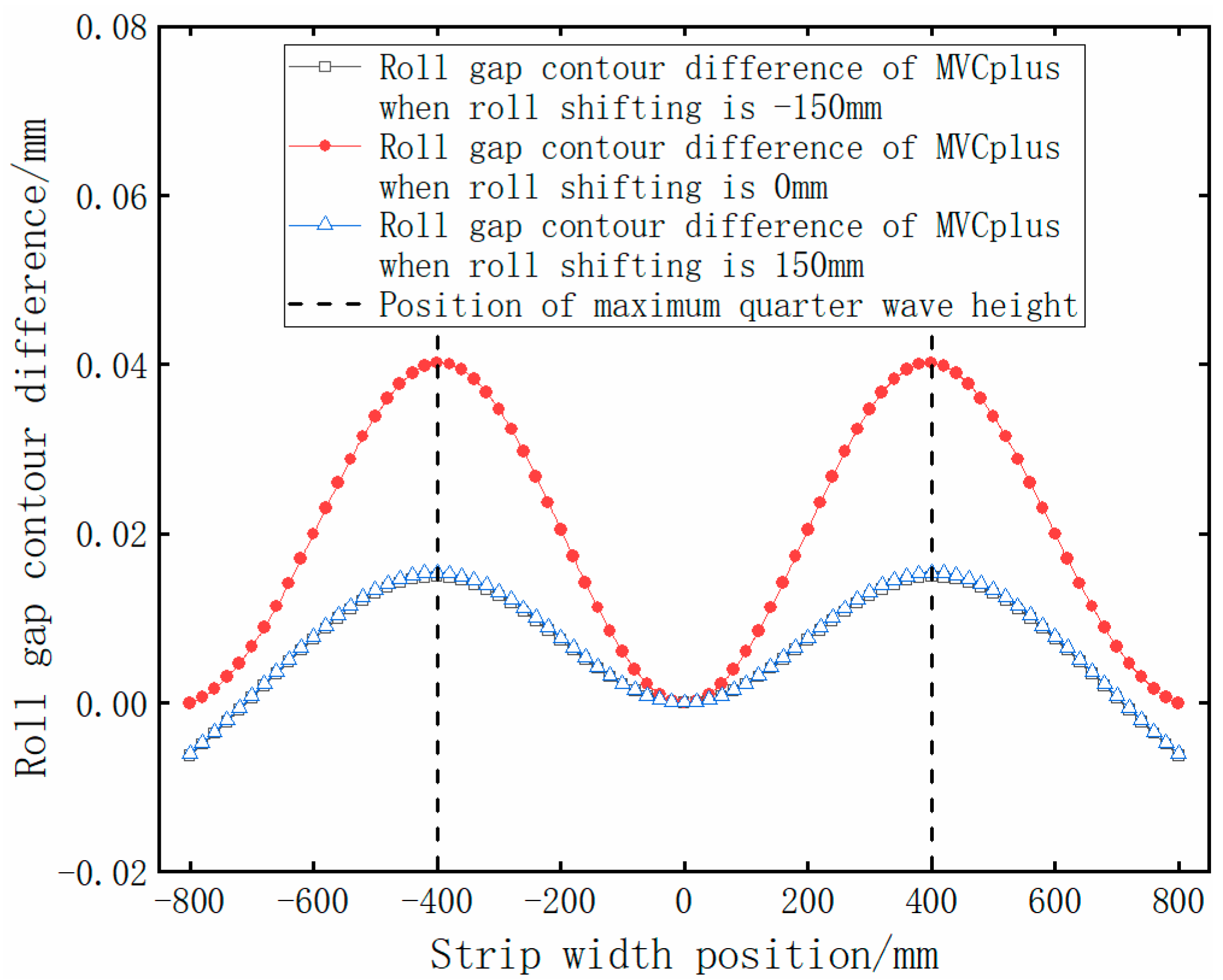
MVCplus hardly changes the CVC’s adjustment characteristics to the quadratic gap crown and has the additional ability to adjust the effective quartic crown of strips. Compared with CVCplus, MVCplus can accurately and locally decrease the reduction where the quarter wave occurs and has less influence on the middle and edge of the strip.
(3)
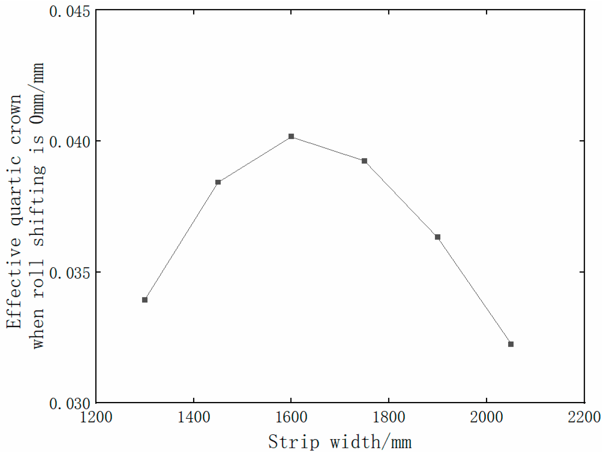
MVCplus has the adjustment ability of effective quartic crown for strips with different widths. When the roll shifting is zero, the adjustment ability of the effective quartic crown reaches its maximum. The adjustment ability gradually decreases when the work roll moves toward the positive limit or negative limit. Due to the normal distribution of the roll shifting distribution, the use frequency near the zero position of the roll shifting is highest, and the compensation effect is optimal in this position.

Author Contributions

Conceptualization, C.L. and A.H.; methodology, A.H.; software, F.W.; validation, R.M., X.Z. and B.M.; formal analysis, H.W.; investigation, C.L. and F.W.; resources, R.M. and X.Z.; data curation, H.W.; writing—original draft preparation, C.L.; writing—review and editing, A.H.; visualization, W.S. and J.S.; supervision, W.S. and J.S.; project administration, R.M. and X.Z.; funding acquisition, C.L. and B.M. All authors have read and agreed to the published version of the manuscript.

Funding

This research was funded by the National Natural Science Foundation of China (grant number 52004029) and the Natural Science Foundation of Heilongjiang Province of China for Distinguished Young Scientists (grant number JQ2022E007). The APC was funded by the National Natural Science Foundation of China (grant number 52004029).

Data Availability Statement

Data is not available due to privacy issues requested by the enterprise partners.

Acknowledgments

The authors would like to thank the National Natural Science Foundation of China (No. 52004029) and the Natural Science Foundation of Heilongjiang Province of China for Distinguished Young Scientists (No. JQ2022E007) for supporting this research.

Conflicts of Interest

The authors declare no conflict of interest.

References

  1. Zhang, G.F.; Shi, H.Y.; Wang, S.T.; Tang, Y.H.; Zhang, X.Y.; Jing, Q.; Liu, R.P. Ultrahigh strength and high ductility lightweight steel achieved by dual nanoprecipitate strengthening and dynamic slip refinement. Mater. Lett. 2023, 330, 133366. [Google Scholar] [CrossRef]
  2. Xiang, S.; Liu, X.T.; Xu, R.; Yin, F.; Cheng, G.J. Ultrahigh strength in lightweight steel via avalanche multiplication of intermetallic phases and dislocation. Acta Mater. 2023, 242, 118436. [Google Scholar] [CrossRef]
  3. Tang, Y.H.; Ji, P.F.; Li, B.; Zhang, G.F.; Ma, W.; Wang, F.; Zhang, X.Y.; Ma, M.Z.; Liu, R.P. Effect of loading on microstructure and friction and wear behavior of an austenite lightweight steel. Tribol. Int. 2023, 177, 108006. [Google Scholar] [CrossRef]
  4. Shin, J.H.; Song, J.Y.; Kim, S.D.; Park, S.J.; Ma, Y.W.; Lee, J.W. Microstructure, Tensile, and Fatigue Properties of Large-Scale Austenitic Lightweight Steel. Materials 2022, 15, 8909. [Google Scholar] [CrossRef] [PubMed]
  5. Lu, Y.; Liu, L.; Meng, J.K.; Chen, Z.; Zhen, L. Strong Yet Ductile Medium Mn Steel Developed by Partial Austenitization. Metall. Mater. Trans. A 2022, 53, 4148–4155. [Google Scholar] [CrossRef]
  6. Schmitt, J.H.; Iung, T. New developments of advanced high-strength steels for automotive applications. Comptes Rendus Phys. 2018, 19, 641–656. [Google Scholar] [CrossRef]
  7. Zhao, J.W.; Jiang, Z.Y. Thermomechanical processing of advanced high strength steels. Prog. Mater. Sci. 2018, 94, 174–242. [Google Scholar] [CrossRef]
  8. Sugimoto, K.; Hojo, T.; Srivastava, A.K. Low and Medium Carbon Advanced High-Strength Forging Steels for Automotive Applications. Metals 2019, 9, 1263. [Google Scholar] [CrossRef] [Green Version]
  9. Matlock, D.K.; Kang, S.; De Moor, E.; Speer, J.G. Applications of rapid thermal processing to advanced high strength sheet steel developments. Mater. Charact. 2020, 166, 110397. [Google Scholar] [CrossRef]
  10. Wang, L.; Dong, C.F.; Man, C.; Hu, Y.B.; Yu, Q.; Li, X.G. Effect of microstructure on corrosion behavior of high strength martensite steel-A literature review. Int. J. Min. Met. Mater. 2021, 28, 754–773. [Google Scholar] [CrossRef]
  11. Li, L.J.; Xie, H.B.; Liu, X.; Liu, T.W.; Wang, E.R.; Jiang, Z.Y. Numerical simulation of strip shape of high-strength steel during hot rolling process. Key Eng. Mater. 2020, 830, 43–51. [Google Scholar] [CrossRef] [Green Version]
  12. Chai, X.J.; Li, H.B.; Zhang, J.; Zhang, Y.Z.; Ma, H.H.; Zhang, P.W. Flatness analysis and control of strips with different thickness in 2250 mm Hot Tandem Rolling. Steel Res. Int. 2018, 89, 1800404. [Google Scholar] [CrossRef]
  13. He, H.N.; Wang, X.C.; Yang, Q. High-precision section control technology for high-strength yoke steel strip. Mater. Sci. Forum. 2019, 944, 212–221. [Google Scholar] [CrossRef]
  14. He, H.N.; Shao, J.; Wang, X.C.; Yang, Q.; Liu, Y.; Xu, D.; Sun, Y.Z. Research and application of approximate rectangular section control technology in hot strip mills. J. Iron Steel Res. Int. 2021, 28, 279–290. [Google Scholar] [CrossRef]
  15. Sun, J.; Shan, P.F.; Wei, Z.; Hu, Y.H.; Wang, Q.L.; Peng, W.; Zhang, D.H. Data-based flatness prediction and optimization in tandem cold rolling. J. Iron Steel Res. Int. 2021, 28, 563–573. [Google Scholar] [CrossRef]
  16. Zhao, J.W.; Wang, X.C.; Yang, Q.; Wang, Q.N.; Liu, C.; Song, G.Y. Precision Shape Model and Presetting Strategy for Strip Hot Rolling. J. Mater. Process. Tech. 2019, 20, 99–111. [Google Scholar] [CrossRef]
  17. Zhao, J.W.; Wang, X.C.; Yang, Q.; Wang, Q.N.; Wang, Y.Y.; Li, W.P. Mechanism of Lateral Metal Flow on Residual Stress Distribution during Hot Rolling. J. Mater Process. Tech. 2020, 288, 116838. [Google Scholar] [CrossRef]
  18. Chen, L.Z.; Sun, W.Q.; He, A.R.; Liu, C.; Qiang, Y. Study on quarter-wave generation mechanism in DP980 steel during cold rolling. Int. J. Adv. Manuf. Technol. 2022, 120, 313–327. [Google Scholar] [CrossRef]
  19. Chen, L.Z.; Sun, W.Q.; He, A.R.; Liu, C.; Qiang, Y.; Zhao, J.W.; Zhou, G.Y.; Yuan, T.H. Research on quarter-wave control in DP980 steel during cold rolling based on multi-pass simulation. Int. J. Adv. Manuf. Technol. 2022, 123, 83–98. [Google Scholar] [CrossRef]
  20. Li, Z.Q.; Liu, Y.M.; Wang, T.; Huang, Q.X. An analytical prediction model of strip crown based on multi-factor interaction mechanism. Int. J. Adv. Manuf. Technol. 2022, 121, 5943–5955. [Google Scholar] [CrossRef]
  21. Sun, J.L.; Peng, Y.; Liu, H.M. Coupled Dynamic Modeling of Rolls Model and Metal Model for Four High Mill Based on Strip Crown Control. Chin. J. Mech. Eng. 2013, 26, 144–150. [Google Scholar] [CrossRef]
  22. Li, G.T.; Gong, D.Y.; Lu, X.; Zhang, D.H. Ensemble Learning Based Methods for Crown Prediction of Hot-Rolled Strip. ISIJ Int. 2021, 61, 1603–1613. [Google Scholar] [CrossRef]
  23. Li, G.T.; Gong, D.Y.; Lu, X.; Wang, Z.H.; Zhang, D.H. Design of a kind of backup roll contour used in four-high CVC hot strip mill. ISIJ Int. 2019, 59, 504–513. [Google Scholar] [CrossRef]
  24. Wang, C.; Wang, D.; Wang, L.P.; Jiang, S.; Li, H.Y.; Li, X.K. The development of time-dependent compensation model for roller CVC profile generation in precision grinding. Int. J. Adv. Manuf. Technol. 2021, 114, 1671–1684. [Google Scholar] [CrossRef]
  25. Liu, G.M.; Li, Y.G.; Huang, Q.X.; Yang, X. Axial force analysis and roll contour configuration of four-high CVC mill. Math. Probl. Eng. 2018, 2018, 7527402. [Google Scholar] [CrossRef] [Green Version]
  26. Li, G.T.; Gong, D.Y.; Xing, J.F.; Zhang, D.H. Optimization of CVC shifting mode for hot strip mill based on the proposed LightGBM prediction model of roll shifting. Int. J. Adv. Manuf. Technol. 2021, 116, 1491–1506. [Google Scholar] [CrossRef]
  27. Shang, F.; Li, H.B.; Kong, N.; Zhang, J.; Hu, C.; Zhang, C.; Cheng, J.F.; Mitchell, D.R.G. Improvement in continuously variable crown work roll contour under CVC cyclical shifting mode. Int. J. Adv. Manuf. Technol. 2017, 90, 2723–2731. [Google Scholar] [CrossRef]
  28. Shang, F.; Li, H.B.; Kong, N.; Zhang, J.; Hu, C.; Chen, L.; Zhang, C.; Chen, J.F. CVC cyclical shifting mode and its working characteristics for the mills of CSP. Int. J. Adv. Manuf. Technol. 2016, 87, 1907–1916. [Google Scholar] [CrossRef]
  29. Li, H.B.; Zhang, J.; Cao, J.G.; Cheng, F.W.; Hu, W.D.; Zhang, Y. Roll Contour and Strip Profile Control Characteristics for Quintic CVC Work Roll. J. Mech. Eng. 2012, 48, 24–30. [Google Scholar] [CrossRef]
  30. Ding, J.G.; He, Y.H.C.; Song, M.X.; Jiao, Z.J.; Peng, W. Roll crown control capacity of sextic CVC work roll curves in plate rolling process. Int. J. Adv. Manuf. Technol. 2021, 113, 87–97. [Google Scholar] [CrossRef]
  31. Berger, S.; Hoen, K.; Hof, H.; Kramer, S.; Seidel, J.; Sudau, P. Evolution of CVC plus (R) technology in hot rolling mills. Metall. Res. Technol. 2008, 105, 44–49. [Google Scholar] [CrossRef]
Figure 1. Quarter wave during hot rolling process of high-strength steel.
Metals 13 00161 g001
Figure 2. Curve of CVC, data from [29].
Metals 13 00161 g002
Figure 3. Curve of CVCplus.
Metals 13 00161 g003
Figure 4. Quadratic gap crown and effective quartic crown of CVCplus.
Metals 13 00161 g004
Figure 5. Roll gap contour of CVCplus in different roll shifting positions. (a) Roll shifting −150 mm; (b) roll shifting 0 mm; (c) roll shifting 150 mm.
Metals 13 00161 g005
Figure 6. Roll gap contour difference between CVCplus and CVC.
Metals 13 00161 g006
Figure 7. Compensation curve for superposition.
Metals 13 00161 g007
Figure 8. Curve of MVCplus after superposition.
Metals 13 00161 g008
Figure 9. Quadratic gap crown and effective quartic crown of MVCplus.
Metals 13 00161 g009
Figure 10. Roll gap contour of MVCplus at different roll shifting positions. (a) Roll shifting −150 mm; (b) roll shifting 0 mm; (c) roll shifting 150 mm.
Metals 13 00161 g010aMetals 13 00161 g010b
Figure 11. Roll gap contour difference between MVCplus and CVC.
Metals 13 00161 g011
Figure 12. Adjustment ability of quadratic gap crown of MVCplus for strips with different widths.
Metals 13 00161 g012
Figure 13. Adjustment ability of effective quartic crown of MVCplus for strips with different widths.
Metals 13 00161 g013
Figure 14. The change in the effective quartic crown of MVCplus with the roll shifting.
Metals 13 00161 g014
Disclaimer/Publisher’s Note: The statements, opinions and data contained in all publications are solely those of the individual author(s) and contributor(s) and not of MDPI and/or the editor(s). MDPI and/or the editor(s) disclaim responsibility for any injury to people or property resulting from any ideas, methods, instructions or products referred to in the content.

