Article

Research on Arc Morphology and Keyhole Behavior of Molten Pool in Magnetically Controlled Plasma-GMAW Welding

1
State Key Laboratory of Advanced Welding and Joining, Harbin Institute of Technology, Harbin 150001, China
2
Shandong Classic Heavy Industry Group Co., Ltd., Jining 272000, China
*
Author to whom correspondence should be addressed.
Metals 2023, 13(1), 148; https://doi.org/10.3390/met13010148
Submission received: 24 November 2022 / Revised: 24 December 2022 / Accepted: 4 January 2023 / Published: 11 January 2023
(This article belongs to the Special Issue Feature Papers in Welding & Joining)

Abstract

:
In the magnetically controlled Plasma-GMAW welding process, the composite arc forms a keyhole in the workpiece to be welded. In order to explore the effect of process parameters on arc coupling, weld pool and keyhole, and the behavior characteristics of keyhole, the arc behavior and side weld pool information were collected using a welding arc acquisition system and a high-speed camera during bead-on-plate welding. The arc image is processed by pseudo-color enhancement technology, and the collected molten pool information is analyzed by boundary extraction algorithm and coordinate conversion algorithm, and the molten pool boundary and keyhole entrance width are obtained. It is found that the coupling degree of the two arcs increases with the increase in plasma current, GMAW current and magnetic field intensity. With the increase in plasma current, the size of keyhole inlet increases; with the increase of GMAW current, the size of keyhole inlet decreases, and the wave crest increases. With the increase of magnetic field intensity, the intensity of metal oscillation between the two arcs increases, and so does the wave crest.

1. Introduction

PAW (Plasma Arc Welding) arc has high energy density and strong penetration ability. GMAW (Gas Metal Arc Welding) has high arc deposition rate [1] and is often used to add filler material to alloy welding [2,3]. Plasma-GMAW welding technology combines the advantages of both, with high melting efficiency, fast welding speed, low welding heat input and low residual stress.
Bai et al. [4] studied droplet transition behavior in aluminum alloy and mild steel Plasma-MIG (Metal-Inert Gas Welding) welding process, and found that MIG current is the main factor affecting droplet transition. Yang et al. [5] found that in the welding process, when the outer plasma current reaches the threshold, it can change the droplet transition mode of composite arc and improve the stability of welding process. Kim et al. [6] compared the difference of droplet transition between Plasma-MIG and MIG through a high-speed camera system, and found that the addition of plasma arc could promote the stable droplet transition. Pulsed current arc welding can produce periodic heat generation and mass transfer process, effectively reduce welding heat input, enhance the stability of welding process and the controllability of droplet transition, and expand the welding specification interval [7,8].
In the welding process, the plasma arc is in the front to produce a deep melting pool, while the MIG arc is in the back, and the welding wire is quickly filled into the melting pool. Two arcs form a common molten pool, which can obtain better penetration depth and width. The research of domestic and foreign scholars also proves this point.
Skowrnska et al. [9] used the Plasma-GMAW hybrid welding technology to weld S700MC high-strength steel, and realized the double-sided forming of a 10 mm thickness plate by welding, reflecting the deep penetration characteristics. When Çağırıcı [10] welds X70M pipeline steel, it needs multi-pass welding when using GMAW arc welding alone, while the Plasma-GMAW welding process only requires single-pass welding, and the mechanical properties of the weld are better. Yurtisik et al. [11] found that compared with single GMAW, the hybrid welding technique significantly improved the efficiency and quality of duplex stainless steel welding.
Since the plasma arc and the GMAW arc in the Plasma-GMAW hybrid welding process adopt DC positive connection and DC reverse connection, respectively, the two arcs interact and burn above the same molten pool. The opposite polarity creates a large repulsive force between the two arcs during welding. Ishida et al. [12] found that during butt welding, not only the arc but also the keyhole formation process can be stabilized by preventing the interference between the two arcs. Therefore, how to solve the problem of repulsion between plasma arc and GMAW arc has always been the research focus of domestic and foreign scholars.
Yu et al. [13,14] found that the GMAW arc generates current shunting and conduction channel superposition through the plasma arc anti-warping tail flame, and the effective coupling degree of the Plasma-pulsed GMAW arc can be significantly enhanced by applying an external magnetic field. Sun et al. [15] conducted research on the hybrid welding process of variable polarity Plasma-GMAW (also known as VPPA-MIG), which can meet the requirements of energy matching and oxide film cleaning in the aluminum alloy welding process.
The coupled arc and droplet transfer behavior of Plasma-GMAW hybrid welding produces impact and heating on the molten pool. The dynamic process characteristic information of keyhole and molten pool oscillation reflects the stability of the welding process and quality of the weld joint. Sun et al. [8] found that the keyhole behavior is closely related to heat transfer and liquid metal flow. Therefore, the molten pool and the keyhole affect the melting and solidification process of the base metal jointly, which is crucial to obtain defect-free, high-quality welds [16].
Zhang et al. [17] observed near infrared radiation from keyholes and molten pools from the bottom of the welded parts with a CCD camera. The keyhole part has strong light and high brightness, while the color of the weld part is darker. Zhang et al. [18] established a prediction model of weld penetration based on high dynamic range imaging, and obtained images of keyhole and weld pool. Both Li et al. [19] and Liu et al. [16] studied the keyhole inlet shape and molten pool behavior by using a double CCD system, and photographed the images of the front molten pool and the keyhole inlet synchronically from the side of the weld and the rear end of the weld. Liu et al. [20] also adopted an image acquisition system with two cameras to simultaneously observe the backside keyhole exit behavior and the frontside melt pool behavior.
In order to overcome the defect that the visual system is difficult to observe the information inside the keyhole, Li et al. [21] used 304 type austenitic stainless steel plate and GG17 glass for butt welding. Observing from the glass side, the inner contour of the keyhole can be directly and clearly observed. Saeed et al. [22] proposed a technique to extract surface information as keyhole depth from acquired images using a calibrated CCD sensor and structured light.
X-rays are also an important means of visual observation. Using two X-ray equipment observation systems, Nguyen Van et al. [23] obtained the formation of the weld keyhole vortex by photographing it from above and below with X-rays. In addition, Cho et al. [24] also qualitatively verified the periodic collapse behavior of the keyhole during welding using high-speed X-ray images.
Indirect observation is to analyze the keyhole through indirect means such as acoustic sensors and voltage sensors. Saad et al. [25] and Wang et al. [26] studied the relationship between acoustic signal and weld pool in variable polarity plasma arc welding. No keyhole mode, transition mode and keyhole mode are identified by acoustic signals. Zhang et al. [7,27] developed a detection sensor for monitoring the state of small holes. It is found that after the keyhole is completely penetrated to form a small hole in the back, the plasma cloud rapidly decreases to zero, so it can be used to detect the keyhole state.
At present, the research on keyholes of molten pool mainly focuses on plasma arc welding, TIG welding, laser welding, etc., but there is still a lack of relevant research on the behavior of keyholes of molten pool in the process of magnetically controlled Plasma-pulse GMAW welding.
The magnetically controlled Plasma-GMAW hybrid welding device and method are used in this paper to apply a constant magnetic field in the direction perpendicular to the welding torch to promote the flexible coupling of the plasma arc and the GMAW arc, reduce the instability of the droplet transfer during the welding process, and achieve the purpose of small welding spatter and improving welding efficiency.
This paper explores the influence of each single factor on the size of the keyhole entrance during the welding process. High-speed cameras are used to capture the molten pool and keyhole information on the side during the welding process, and image processing technology is used for analysis and processing. At the same time, the physical characteristics of the arc are studied, and the connection between arc, keyhole and forming is found.

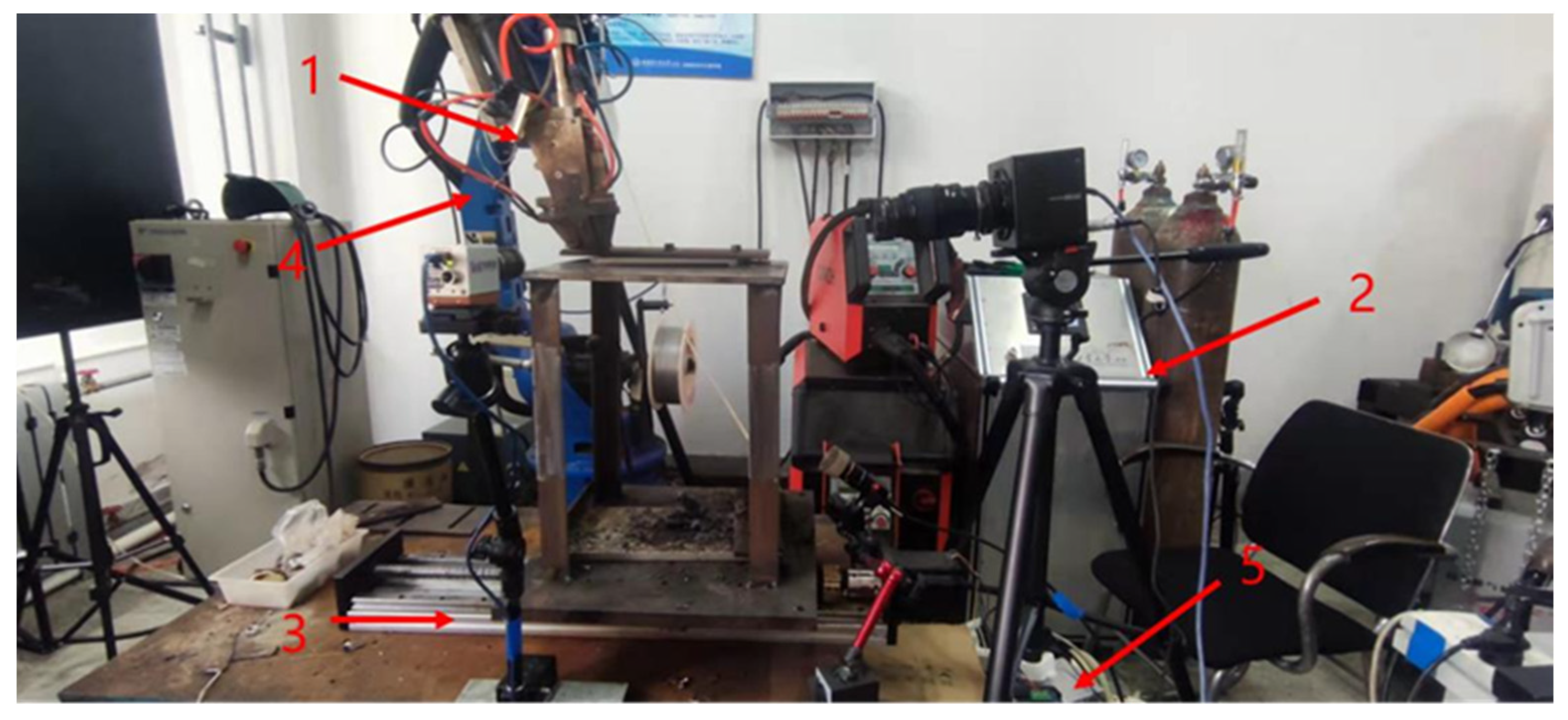
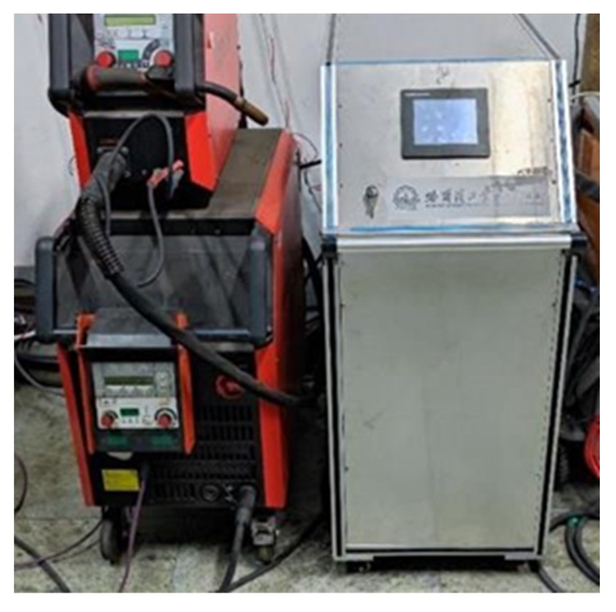
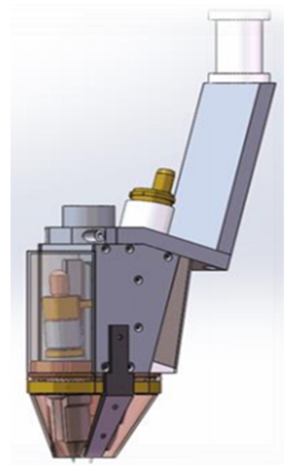
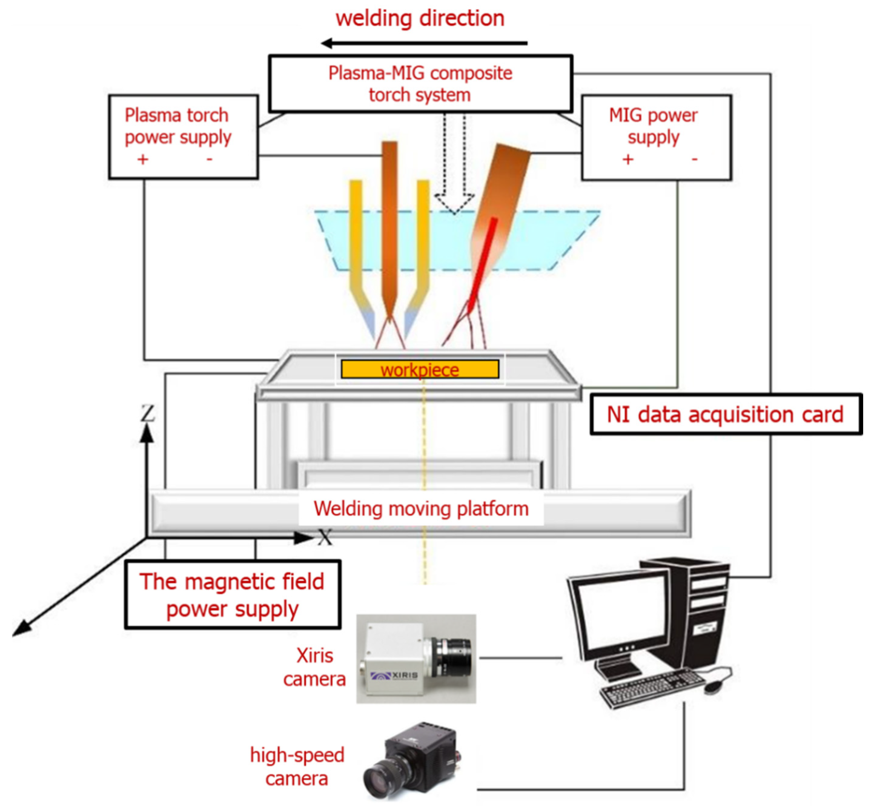
2. Materials and Methods

The magnetically controlled Plasma-GMAW hybrid welding system used in this paper was built by the laboratory, and the hybrid welding torch and welding power source are designed by the laboratory. The control system includes a time controller, servo motor and welding machine start and end signal control.
During the welding process, the base metal is fixed on the welding test platform, the traveling mechanism drives the welding test platform to move, and the positions of the welding torch and each signal acquisition system remain unchanged.
Before welding, the composite welding torch is adjusted to the top of the workpiece to be welded by the robot, and the moving speed of the workpiece is adjusted by the walking mechanism controlled by the servo motor. In order to ensure the orderly progress of the whole welding process, the ventilation, arc starting, mechanism walking and arc extinguishing during the welding process are controlled by the time controller.
The overall distribution diagram of the welding system is shown in Figure 1, which mainly includes: 1. Composite welding torch; 2. Image signal acquisition system; 3. Welding motion platform; 4. Welding robot; 5. Welding process control system. Plasma power supply and GMAW power supply are shown in Figure 2, the magnetic current controller is integrated into the plasma power supply control cabinet. The welding robot used is YASKAWA arc welding robot.
Figure 3 shows the hybrid torch, which integrates the plasma torch and the GMAW torch. The magnetic control function is completed by the magnetic coil inside the welding torch and the shaped magnet outside the welding torch.
The base material used was 304 stainless steel (ASME grade, 06Cr19Ni10), tensile strength σb (MPa) ≥ 520, conditional yield strength σ0.2 (MPa) ≥ 205, elongation δ5 (%) ≥ 40, section shrinkage ψ (%) ≥ 60, hardness ≤ 187 HB; 90 HRB; 200HV, and its chemical composition is shown in Table 1. The size of the test plate used is 200 mm × 50 mm × 8 mm, before welding, the stainless-steel surface is cleaned by mechanical grinding. After grinding, acetone and alcohol are used to wipe the surface of the base metal to avoid the influence of external surface impurities on the weld. The GMAW welding wire is ER304, the diameter is 1.2 mm, the main component is 18Cr-8N and the chemical composition is shown in Table 2.
In order to obtain the real-time changes of the molten pool and keyhole in the welding process, a high-speed camera was used to photograph. The high-speed camera acquisition system includes high speed camera, NI data acquisition card of PCI-6251 and main control computer. The acquisition frequency is 500 frames per second, and the size of each frame is 640 × 480. The distance between the high-speed camera and the center of the weld is 400 mm in the horizontal direction and 125 mm in the vertical direction.
Arc shape is an important method to judge the stability of welding process. The arc form data acquisition system is the Xiris XVC-1000 weld camera (55 frames/s acquisition rate), and the schematic diagram is shown in Figure 4. In order to ensure the acquisition effect, the whole camera includes COMS lens, filter and protection plate. Among them, the filter is an infrared bandpass filter (filter is added to avoid the damage of strong light to the lens), the central wavelength is 808 nm (the spectral intensity is very high near the band), and the aperture is adjusted to 16. The horizontal distance between the camera and the center of the weld is 280 mm.
In this paper, a single-factor flat surfacing test is designed. Through the welding arc morphology acquisition system and high-speed camera acquisition system, the arc behavior and side weld pool behavior during the flat surfacing process are observed, and the pseudo-color enhancement technology, image processing and coordinate conversion are used to analyze the collected results.
In the process of designing the experiment, plasma current (IP), GMAW current (IM) and magnetic field strength (B) are mainly studied. There are 5 groups of experiments for each parameter, and the following 13 groups of experiments are designed, as shown in Table 3. Among them, the group with test number 1 is the core parameter group, which can be compared with other groups, respectively. In the five groups numbered 2, 3, 1, 4, 5, only plasma current changes, which are 180 A, 190 A, 200 A, 210 A and 220 A, respectively. The other parameters are IM = 300 A, B = 1.65 mT, velocity(v) = 7.5 mm·s−1. In the five groups numbered 6, 7, 1, 8, 9, only GMAW current changes, which are 280 A, 290 A, 300 A, 310 A and 320 A, respectively. The other parameters are IP = 200 A, B = 1.65 mT, v = 7.5 mm·s−1. In the five groups numbered 10, 11,1, 12 and 13, only the magnetic field intensity changed, which are 0 mT, 0.825 mT, 1.65 mT, 2.475 mT and 3.3 mT, respectively. The other parameters were IP = 200 A, IM = 300 A, v = 7.5 mm·s−1. In addition to the above specification parameters, the other main parameters are: the height of the welding torch is 5 mm, the flow rate of plasma gas is 3 L/min, the flow rate of shielding gas is 20 L/min, and the plasma gas and shielding gas are all pure argon gas.

3. Results and Discussion

3.1. Physical Properties of Plasma-GMAW Composite Arc Morphology

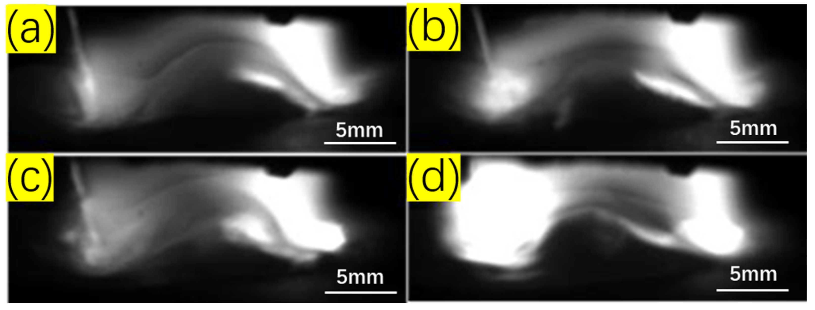
3.1.1. Effect of Plasma Current on Arc Morphology

For a single plasma arc, when other conditions are given, increasing the welding current will enhance the penetration ability and straightness of the plasma arc, making it less susceptible to the influence of external environment.
When the plasma current changes, the arc shape of the Plasma-GMAW welding in one cycle of shape transformation is shown in Figure 5. False-color processing software Xiris Weld Studio™ (2.0.3, Xiris Automation, Burlington, ON, Canada) can transform the grayscale image captured by the CCD camera into a false-color image to display the arc profile and shape more intuitively. The upper part of each image is the original arc shape image taken by the xiris camera, and the lower part is the arc shape map after pseudo-color enhancement. The left side of the picture is the GMAW arc, and the right side is the plasma arc. For each plasma current, the first diagram (a1, b1, c1, d1, e1) shows the arc shape when GMAW current is at the base value. The second diagram (a2, b2, c2, d2, e2) shows the arc shape when GMAW current is between the base value and the peak value. The third diagram (a3, b3, c3, d3, e3) shows the arc shape when the GMAW current is at its peak.
When the plasma current is 180 A, since the GMAW current is in pulse mode, there is a current base value and a current peak value. In Figure 5a1, the pulse current is at the base value, the arc repulsion force between the two arcs is small, and the coupling force of two arcs generated by the external magnetic field in the welding arc space is greater than the repulsion force at this time, so it can be observed that the plasma arc column is significantly shifted to the left. Figure 5a3 shows the arc shape when the pulse current is at its peak. At this time, the GMAW current is larger, so the repulsive force between the two arcs is also larger, and the repulsive force at this time is greater than the coupling force between the two arcs, so the plasma arc column is slightly inclined to the right, and the angle of inclination is not large. Observing Figure 5a2, it is found that the coupling effect between the two arcs is good.
It is found that when the GMAW current is at the peak value, the plasma arcs in each group of tests have different degrees of right inclination, that is, the coupling force generated by the magnetic field on the two arcs is smaller than the repulsive force generated by the peak GMAW current. With the increase in plasma current, the shape of arc coupling also changes. Comparing the peak current time diagram, it is found that with the increase of Plasma current, the boundary between the two arcs is gradually blurred, and the coupling effect is gradually obvious. The coupling degree is higher when the plasma current parameters are 210 A and 220 A.
The swing amplitude of the plasma arc column first increases and then decreases with the increase in the plasma current. The swing amplitude increases first, probably because the repulsive force between the arcs increases more significantly with the increase of the plasma current. When the current is greater than 200A, the swing amplitude of the arc decreases, which may be because the increase in the current leads to the enhancement of the straightness of the arc.
Take any three arc coupling change cycles in the stable stage of the welding process and take the average value of their cycles. When the plasma current is 180 A, 190 A, 200 A, 210 A and 220 A, the arc coupling change cycles are 0.14 s, 0.15 s, 0.14 s, 0.16 s and 0.19 s, respectively. With the increase in plasma current, the change period of welding arc coupling shows an overall increasing trend.

3.1.2. Effect of GMAW Current on Arc Morphology

The use of pulsed GMAW can improve the transfer mode of the droplet during the welding process, thereby affecting the stability of the welding process. In Plasma-GMAW welding, when the GMAW current and pulse frequency are appropriate, stable droplet transfer can be achieved, otherwise, welding spatter and arc breakage will occur.
When the GMAW current changes, the arc shape of the Plasma-GMAW welding in one morphological transformation period is shown in Figure 6. For the three graphs of each GMAW current, the first graph (a1, b1, c1, d1, e1) is the arc shape when GMAW current is at the base value, the second graph (a2, b2, c2, d2, e2) is the arc shape when GMAW current is between the base value and the peak value, and the third diagram (a3, b3, c3, d3, e3) shows the arc shape when the GMAW current is at its peak.
As shown in Figure 6, when the GMAW current is 280 A, only the arc at the peak moment (a3) is perpendicular to the workpiece, and the arc is in a state of being tilted to the left at other times, which shows that when the GMAW current is small, except for the peak value of the GMAW current, the repulsive force between the two arcs is small (smaller than the coupling force generated by the magnetic field). Therefore, the plasma arc is in a state of being tilted to the left most of the time. With the increase of GMAW current, the plasma arc column gradually begins to deflect to the right, and the amplitude of the deflect to the right also increases gradually.
On the whole, the coupling degree between the two arcs gradually increases with the increase in GMAW current, but when the current value is greater than 300 A, the coupling degree does not change significantly. This is because the GMAW arc is inclined towards the plasma arc, and the straightness of the arc makes the GMAW arc close to the plasma arc, improving the coupling effect.
When the GMAW current is 280 A, 290 A, 300 A, 310 A and 320 A, the arc coupling change period is 0.15 s, 0.15 s, 0.14 s, 0.18 s and 0.18 s, respectively. With the increase in GMAW current, the change period of welding arc coupling shows an overall increasing trend, which is consistent with the change law when plasma current increases.

3.1.3. Effect of Magnetic Field Strength on Arc Morphology

The purpose of adding a magnetic field in the hybrid welding process is to improve the coupling degree of the arc, so when the magnetic field strength changes, the arc shape also changes. When the magnetic field intensity changes, the arc shape of Plasma-GMAW welding in one morphological transformation period is shown in Figure 7. For the three graphs of each magnetic field intensity, the first graph (a1, b1, c1, d1, e1) is the arc shape when GMAW current is at the base value, and the second graph (a2, b2, c2, d2, e2) is the arc shape when GMAW current is between the base value and peak value. The third diagram (a3, b3, c3, d3, e3) shows the arc shape when the GMAW current is at its peak.
As shown in Figure 7, the arc shape when the magnetic field strength is 0 mT (that is, without a magnetic field) is significantly different from that when there is a magnetic field. When there is a magnetic field, the plasma arc has two states: left swing and right swing, but when there is no magnetic field, the arc has no left swing state. Only when the GMAW current is at the base value and the repulsive force between the two arcs is small, the plasma arc can be perpendicular to the workpiece, and it is in a right swing state at other times.
Comparing the arc shapes under different magnetic field strengths, it is found that when the magnetic field strength is small, the coupling effect of the arc is poor. When the magnetic field strength is greater than 1.65 mT, a good coupling can be achieved between the two arcs, and the coupling degree increases with the increase in magnetic field intensity.
When the magnetic field strengths are 0 mT, 0.825 mT, 1.65 mT, 2.475 mT and 3.3 mT, the arc coupling change periods are 0.18 s, 0.23 s, 0.14 s, 0.18 s and 0.23 s, respectively. It was found that the effect of magnetic field strength on the arc coupling variation period did not show a certain linear change.

3.2. Influence of Process Parameters on Keyhole Entrance Morphology and Molten Pool Boundary

The process parameters have an effect on the entrance size of the keyhole and the morphology of the molten pool during the hybrid welding process. A high-speed camera is used to obtain the surface image of the molten pool during the welding process, and the boundary of the molten pool is extracted by the image processing method, and then the size information of the keyhole entrance and the morphology of the molten pool are analyzed.
The morphology of the molten pool at the beginning of welding was observed, as shown in Figure 8. During the welding process, the plasma torch starts a small arc first, then the large arc starts after 2 s, and the GMAW starts after 2 s. The welding zero time is defined as the moment when the plasma torch starts a small arc.
Before the GMAW arc starts, the plasma arc starts first. Due to the concentration of the plasma arc energy, the vertical downward arc force is relatively large. When the molten pool is formed, the molten metal will be expelled to the surrounding area, and there is an obvious molten pool after the plasma arc. Figure 8a shows the moment when the GMAW arc starts. Since there is an included angle between the GMAW arc and the plasma arc, the molten metal in the molten pool behind the plasma arc moves backwards and flows back due to the force of the GMAW arc during the welding process. A crest of molten pool is formed between the two arcs, and as the soldering process progresses, the wave crest decreases gradually.
The GMAW current is in a pulsed mode. Under the combined action of the intermittent GMAW arc force and the continuous plasma arc force, the crest of the molten pool oscillates back and forth between the two arcs. After entering the stable stage, the height of the wave crest changes within a certain range, the change area of the wave crest does not change, and the molten pool is constantly oscillating. After the welding process is stabilized, the weld pool and keyhole boundaries do not change much, so they can be used as the characteristics of the welding stabilization stage.

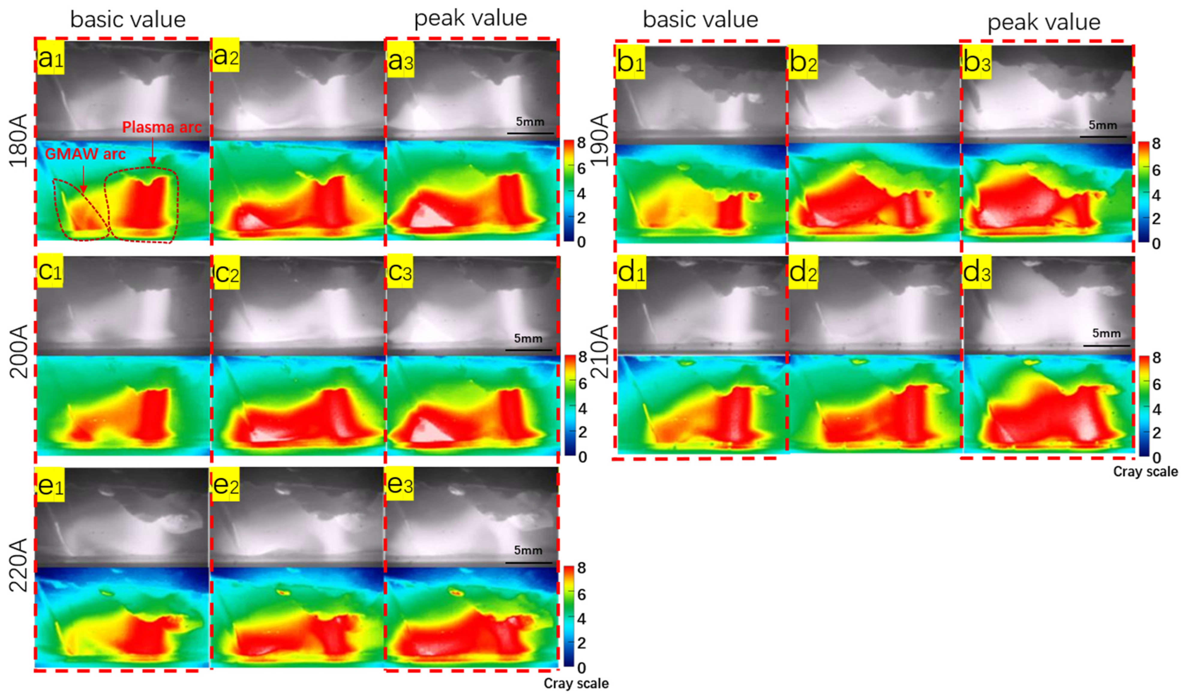
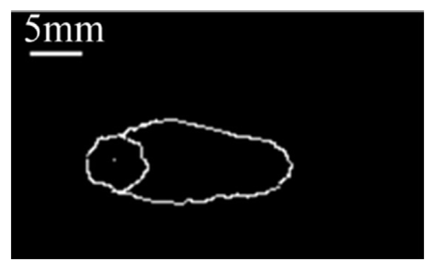
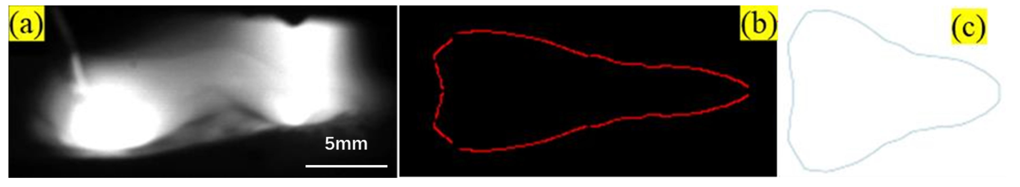
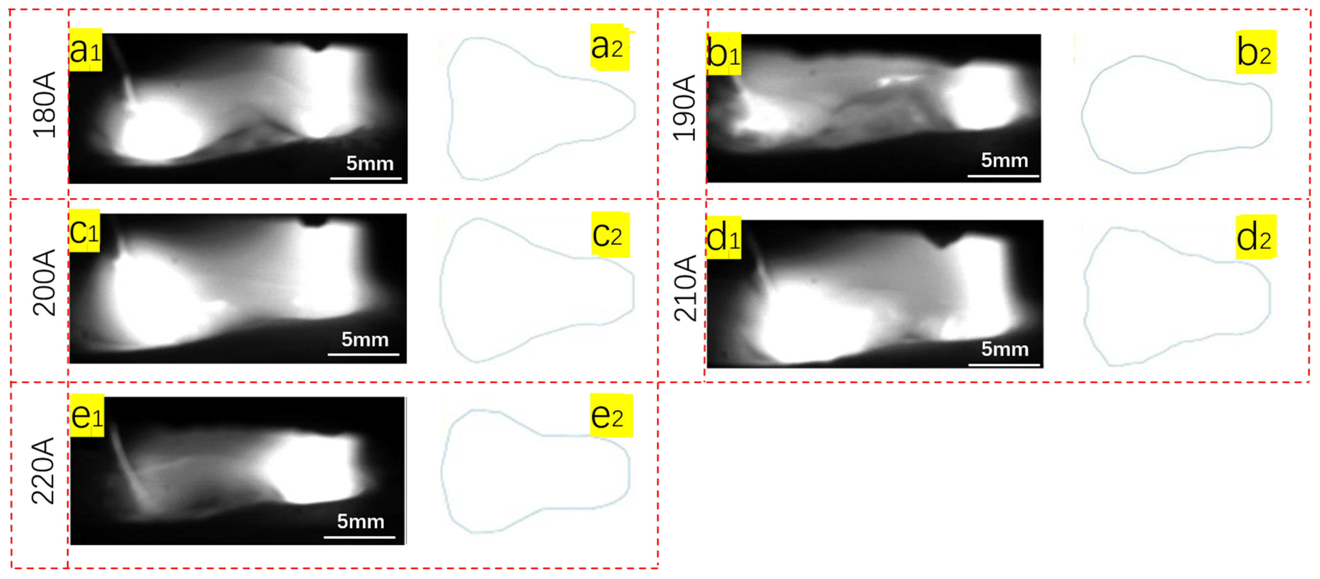
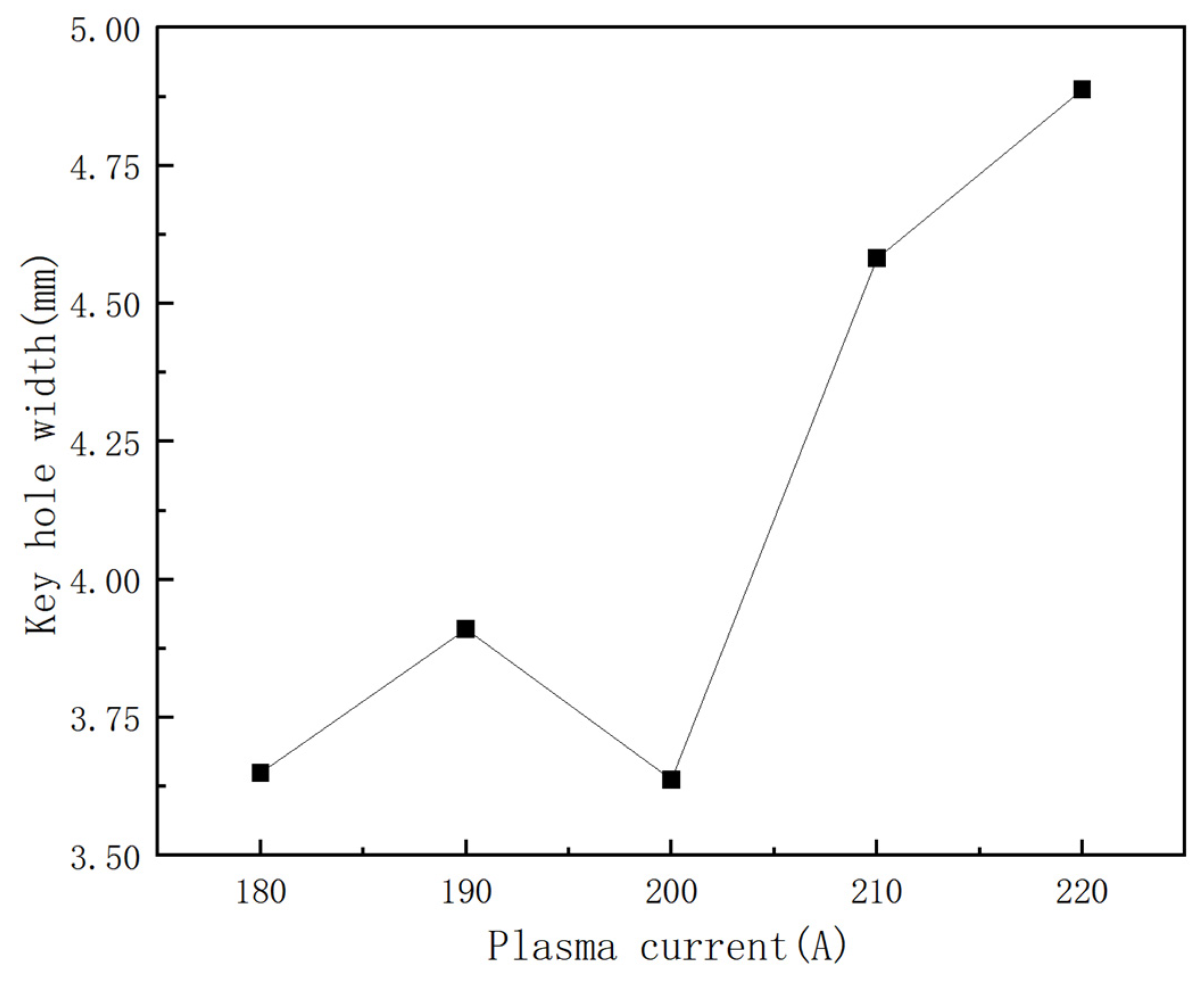
3.2.1. Influence of Plasma Current on Keyhole Entrance Morphology and Weld Pool Boundary

Since a single camera cannot observe the complete melt pool information, in this experiment, the captured side keyhole and melt pool images are processed for image processing, that is, the canny algorithm is used to extract the melt pool boundary. It is assumed that the two sides of the molten pool are approximately symmetrical, and the obtained graph is transformed symmetrically. Finally, the molten pool and keyhole images on the side are converted into frontal images by coordinate transformation.
As shown in Figure 9 [16], Liu et al. found in their experiments that for plasma welding, the keyhole boundary and the weld pool boundary are roughly the same, so this paper uses the front part of the restored plasma weld pool boundary as the keyhole boundary.
Figure 10a shows the lateral molten pool and keyhole images after the welding process reaches a quasi-steady state (the width of the molten pool and the width of the keyhole do not change). The arc on the right is the plasma arc, and the arc on the left is the GMAW arc, Figure 10b is the extracted molten pool boundary, Figure 10c is the frontal molten pool boundary obtained by coordinate transformation.
Figure 11 shows the molten pool and keyhole boundary at the stable stage at different plasma currents. For the two images of each plasma current, the first one (a1, b1, c1, d1, e1) is the side molten pool and keyhole image after the welding process reaches the quasi-steady state, and the second one (a2, b2, c2, d2, e2) is the front molten pool boundary recovered by coordinate transformation. The shape of the right boundary reflects the keyhole entrance morphology of the plasma arc, and the shape of the left boundary reflects the weld pool boundary morphology of GAMW arc.
Compared with the arc starting stage in Figure 8, the peak height of the molten pool between the two arcs is smaller in the stable stage, more heat is generated, and the overall vision becomes brighter. From the extracted molten pool and keyhole boundary, it can be found that the size of the keyhole formed by the plasma arc is smaller than that of the molten pool formed by the GMAW arc, and the overall shape is like a gourd.
With the increase in plasma current, the position of the maximum molten pool width moves backward. This is because the repulsive force between arcs increases with the increase in plasma current, and the molten metal tends to move backward under the action of the repulsive force.
From the molten pool boundary obtained at different plasma currents, the width of the front keyhole entrance is calculated and drawn as a line graph, as shown in Figure 12. It can be seen from the figure that with the increase in the plasma current, the size of the keyhole entrance shows an overall upward trend. When the plasma current value is greater than 200 A, this trend is very obvious. This is related to the energy input of the plasma current. Under other conditions being the same, if the plasma current increases, the arc force generated increases, the heat input to the weldment increases, and the molten metal generated increases, so the keyhole entrance width increases. Combining the above, it can be seen that with the increase in plasma current, the arc coupling effect becomes better, and the width of the keyhole increases.

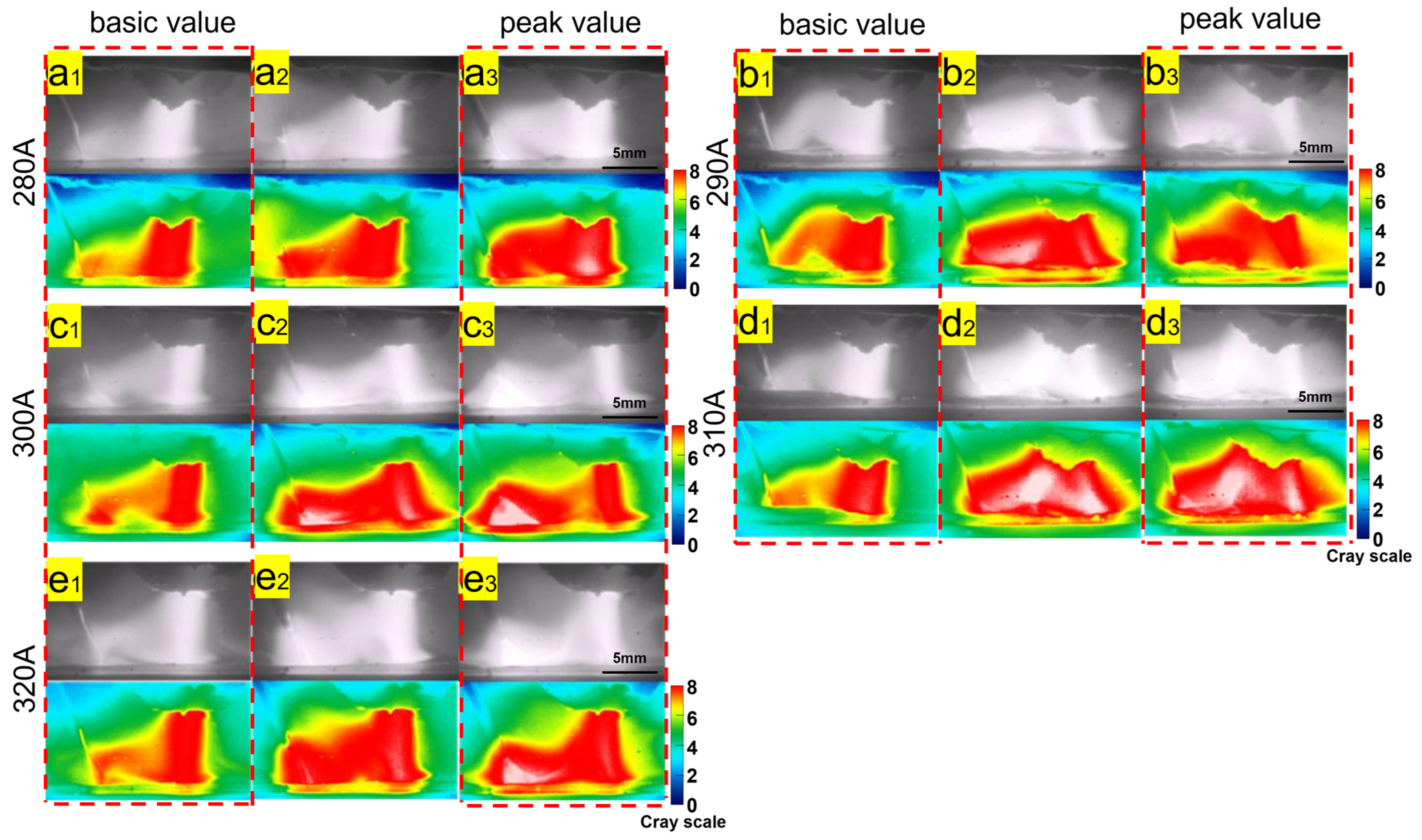
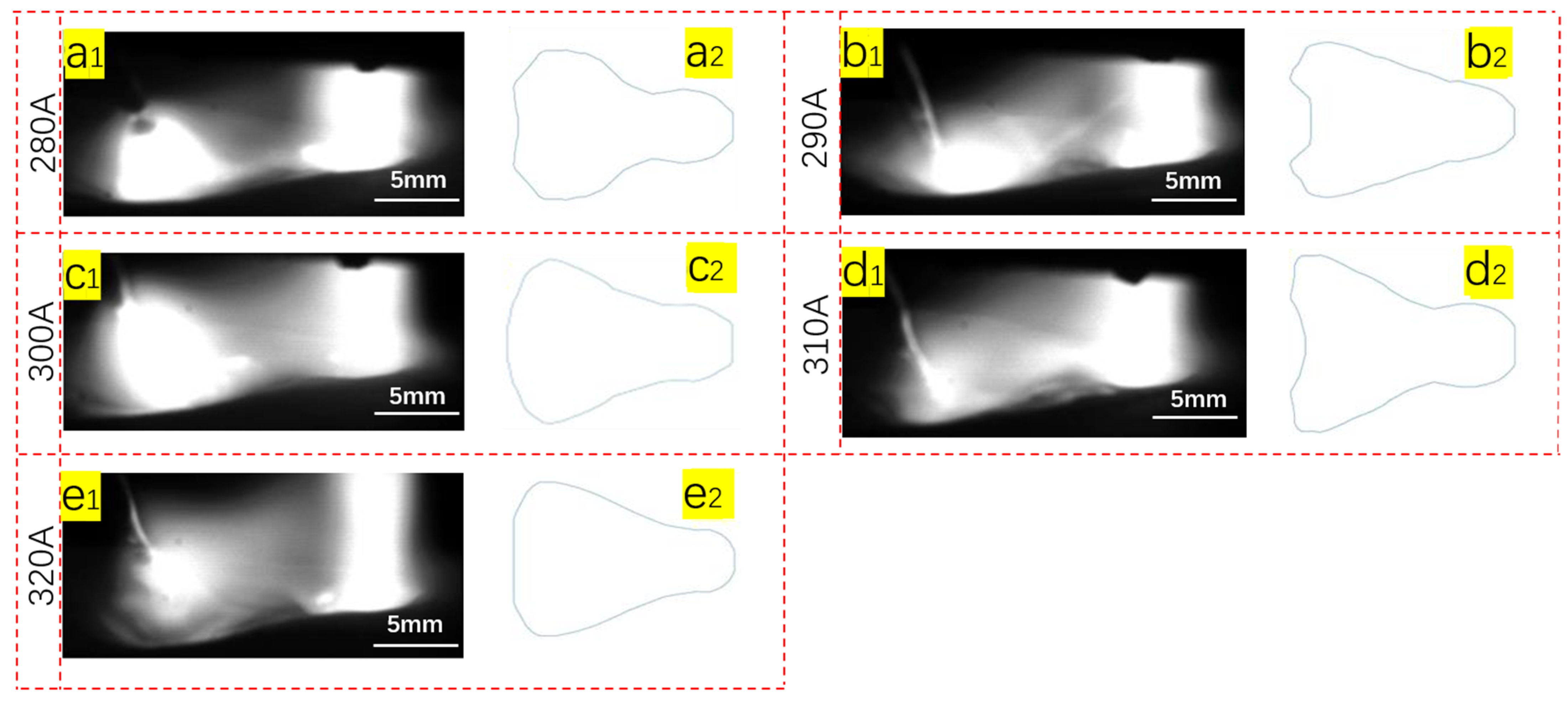
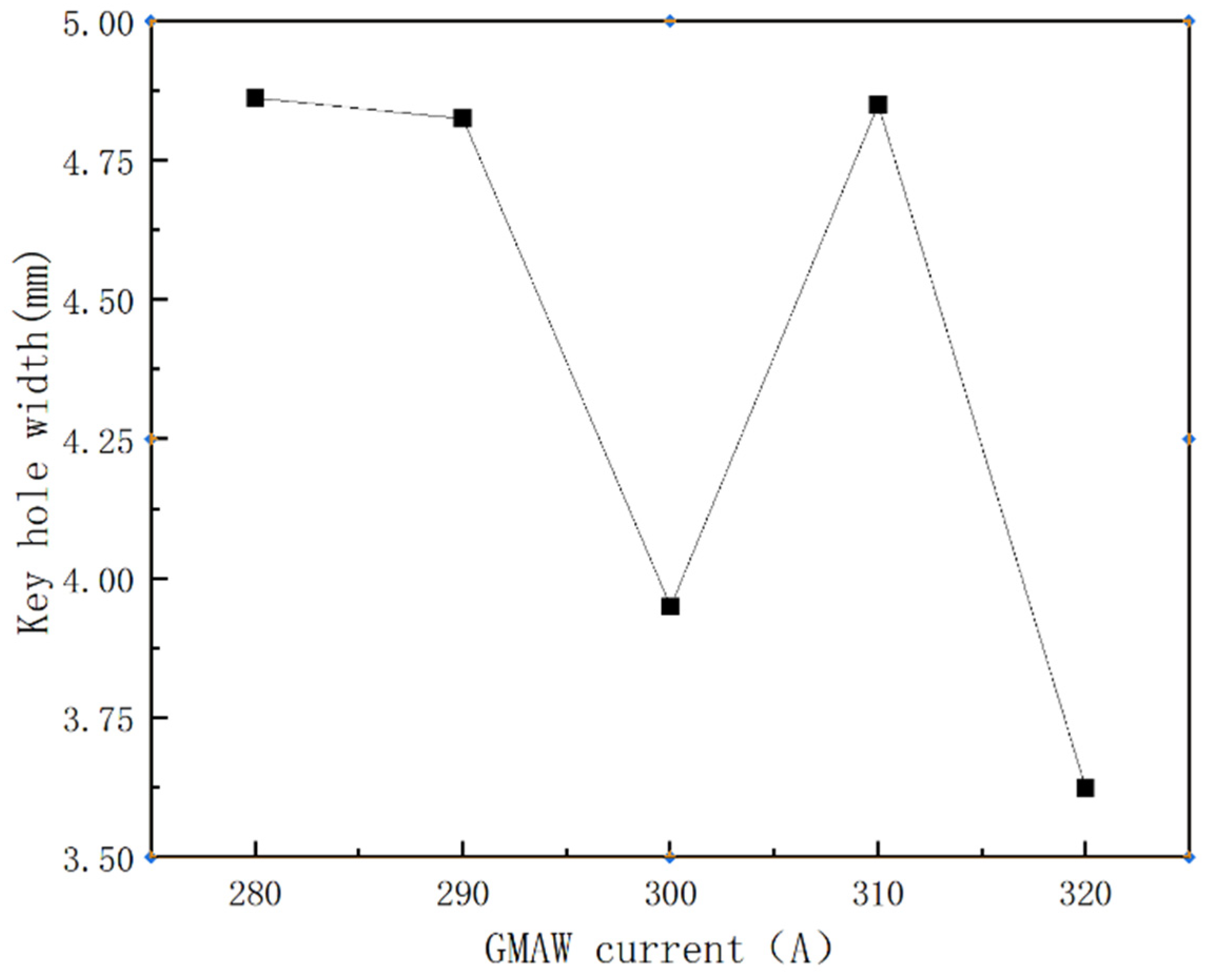
3.2.2. Influence of GMAW Current on Keyhole Entrance Morphology and Weld Pool Boundary

Figure 13 shows the molten pool and keyhole boundary at the stable stage at different GMAW currents. For the two images of each GMAW current, the first one (a1, b1, c1, d1, e1) is the side molten pool and keyhole image after the welding process reaches the quasi-steady state, and the second one (a2, b2, c2, d2, e2) is the front molten pool boundary recovered by coordinate transformation.
Observing the side weld pool and keyhole images (a1, b1, c1, d1, e1), it can be found that under other conditions being the same, the peak height of the molten pool between the two arcs gradually increases with the increase in the GMAW current. When the GMAW current is 280 A, it is difficult to see a molten metal peak between the two arcs through the tail flame of the GMAW arc. When the GMAW arc is 310 A and 320 A, there are obvious molten metal peaks between the two arcs. This is because the increase of GMAW current leads to an increase in the amount of molten metal of the welding wire, which cannot flow to both sides in time, so it accumulates between the two arcs, resulting in an increase in the peak height of the molten metal between the two arcs.
In addition, observing the above original image, it was also found that with the increase in GMAW current, the arc column area of plasma arc showed a decreasing trend. This is because during the welding process, the plasma welding torch is DC positive connection, and the GMAW welding torch is DC reverse connection, and there is a current flowing directly from the GMAW welding torch to the plasma welding torch between the two welding torches. As the GMAW current increases, the current flowing from the GMAW torch to the plasma torch increases, so the current value between the plasma torch and the workpiece decreases, resulting in a gradual decrease in the arc column area of the plasma arc.
Comparing the weld pool boundaries and morphologies of keyhole entrances at different GMAW currents, all weld pool boundaries show a gourd-like shape, but there is an obvious “necking” between the two arcs. This is because during the welding process, there is less molten metal in the area behind the plasma arc close to the weld pool boundary, which appears as a darker area in the optical high-speed camera, thus showing a “necked” boundary in the weld pool boundary restoration map. However, this does not mean that the actual molten pool boundary exhibits a “necked” phenomenon, and in fact there is still molten metal on both sides of the “necked” area.
As shown in Figure 14, with the increase of GMAW current, keyhole width generally presents a decreasing trend, but the variation range is small. This is related to the current flow between the two welding torches. The increase of the GMAW current causes the current between the plasma torch and the welded part to decrease, so the width of the keyhole inlet decreases slightly.

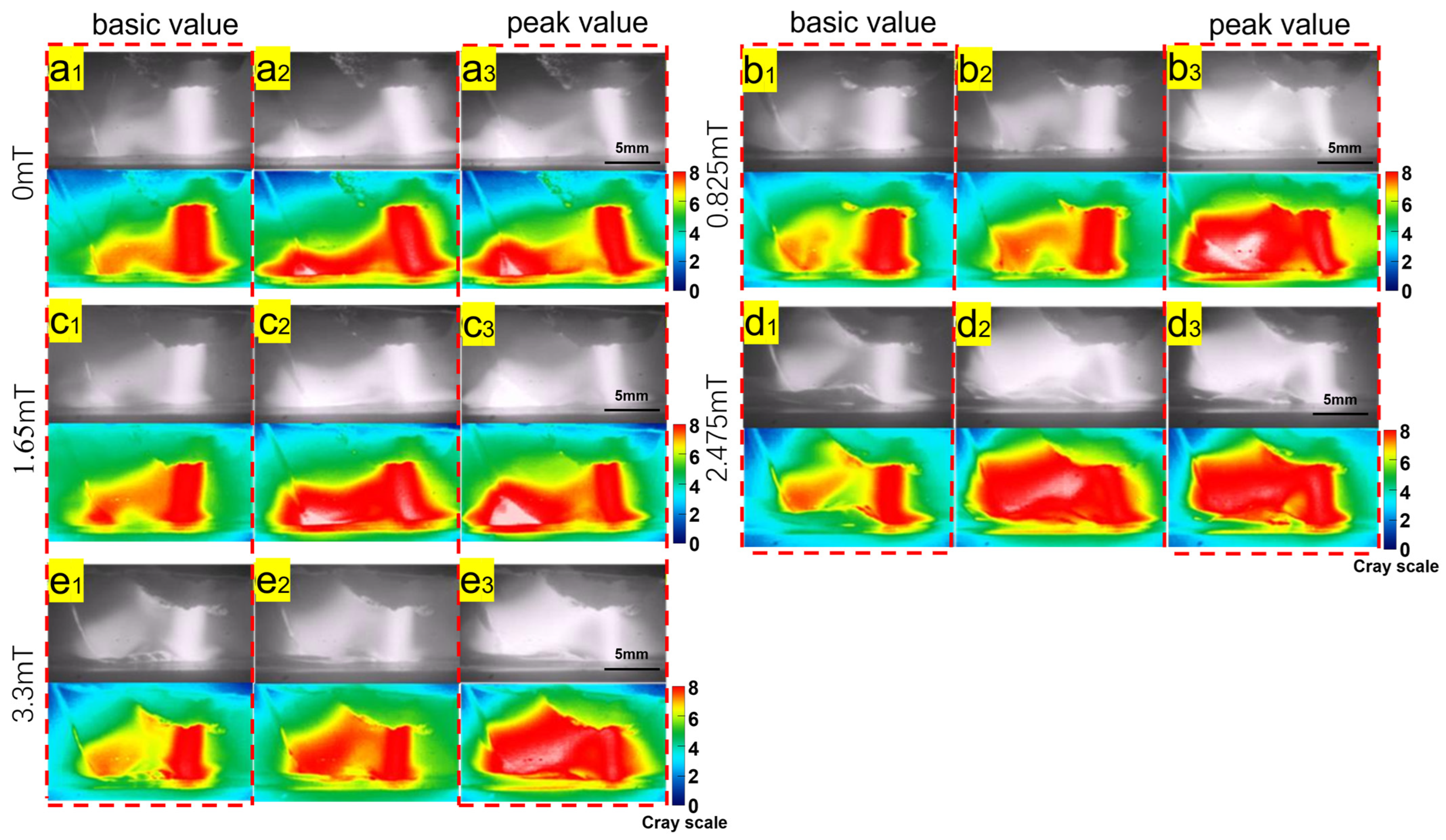
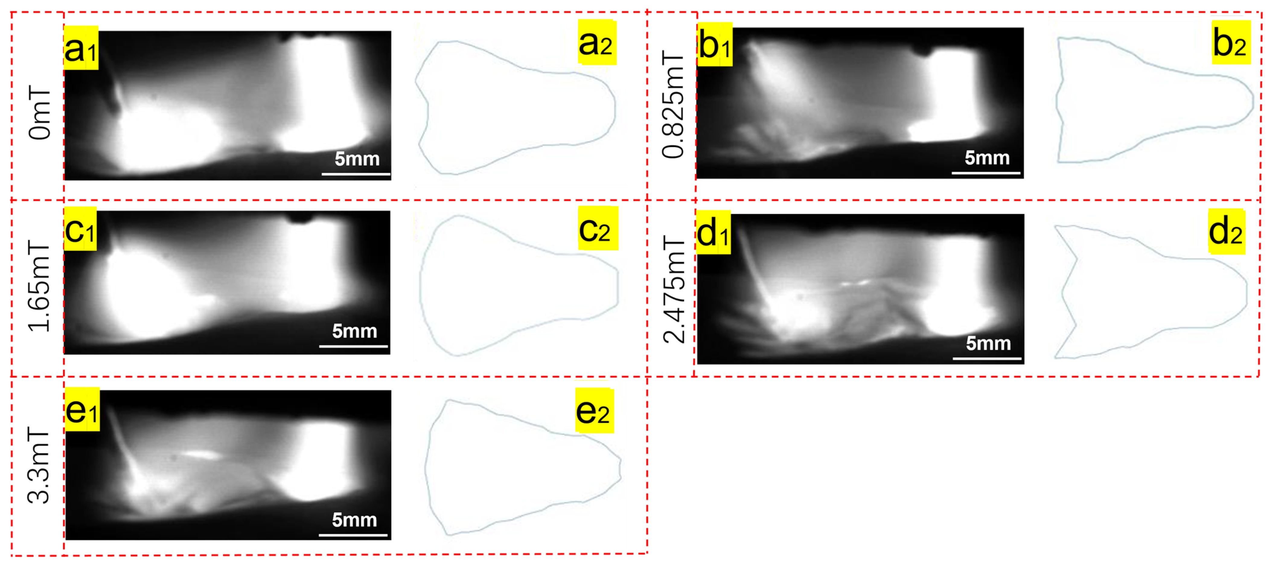
3.2.3. Influence of Magnetic Field Strength on Keyhole Entrance Morphology and Weld Pool Boundary

Figure 15 shows the changes of the keyhole entrance morphology and the weld pool boundary in the stable welding stage when the magnetic field strength changes. Observing the side weld pool and keyhole images (a1, b1, c1, d1, e1), with the increase in the magnetic field strength, the swing direction of the plasma arc column gradually changes from right to left. The peak height of molten metal between two arcs slightly increases with the increase in magnetic field intensity, and the intensity of molten pool metal oscillation between two arcs also increases with the increase in magnetic field intensity. This is because the degree of coupling increases as the magnetic field strength increases.
When the intensity of the magnetic field increases, the curve of the middle transition between the keyhole entrance and the side boundary of the molten pool becomes softer and the corner becomes smaller. When the magnetic field intensity is 3.3 mT, the boundary becomes almost a smooth straight line. This is because with the increase in the magnetic field strength, the coupling effect between the two arcs becomes better, the coupled arc has a better heating effect on the metal in the middle part of the two welding torches, and the transition between the weld pool boundaries is smoother.

4. Conclusions

In this paper, the influence of the main process parameters on the physical properties of the composite arc, the morphology of the keyhole entrance and the weld pool boundary during the welding process is studied. The following conclusions are drawn:
(1)
With the increase in plasma current, the coupling degree of the two arcs increases, and the best are 210 A and 220 A. The deviation degree of plasma arc column increases first and then decreases with the increase in plasma current. With the increase in plasma current, the arc coupling period becomes longer. With the increase in GMAW current, the arc coupling degree increases, and when the current value is greater than 300 A, the change of current coupling degree is not obvious. The coupling period of welding arc increases with the increase in GMAW current. As the magnetic field intensity increases, the arc coupling degree increases.
(2)
A molten pool wave crest is created between the two welding arcs. During the welding process, the wave crest oscillates back and forth between the two arcs. The wave crest of GMAW is the largest when the arc starts, and then gradually decreases. With the increase in plasma current, the size of the keyhole entrance shows an overall upward trend, and the position of the maximum pool width moves backward. The increase in GMAW current results in a decrease in the area of the plasma arc column, resulting in a decrease in the keyhole inlet size. The peak height of the molten pool crest between two arcs increases with the increase of the GMAW current. All the molten pool boundaries are gourd-like, but there is an obvious “neck contraction” between the two arcs. The peak height of molten metal between the two arcs increases slightly with the increase of magnetic field intensity, and the intensity of molten pool metal oscillation between the two arcs also increases with the increase in magnetic field intensity.

Author Contributions

Conceptualization, H.Z. and X.M.; methodology, H.Z. and X.M.; investigation, X.M., H.Z., F.G. and Z.H.; writing—original draft preparation, H.Z., J.G. and X.M.; writing—review and editing X.M., H.Z., Z.S. and Z.H. All authors have read and agreed to the published version of the manuscript.

Funding

This research was funded by National Natural Science Foundation of China, grant number 52175305, Jining City Global List of Major Projects, grant number 2022JBZP004, and National Natural Science Foundation of China (U22B20127).

Institutional Review Board Statement

Not applicable.

Informed Consent Statement

Not applicable.

Data Availability Statement

Not applicable.

Acknowledgments

The work was financially supported by National Natural Science Foundation of China (52175305), Industrial Innovation Major Technology Global Unveiling Project of Jining City (2022JBZP004), the new and old kinetic energy conversion major industrial research projects in Shandong Province in 2021, Key Supported Projects of the Enterprise Joint Fund of the National Natural Science Foundation of China (U22B20127).

Conflicts of Interest

The authors declare no conflict of interest.

References

  1. Rodrigues, T.A.; Duarte, V.R.; Miranda, R.M.; Santos, T.G.; Oliveira, J.P. Ultracold-Wire and Arc Additive Manufacturing (UC-WAAM). J. Mater. Process. Technol. 2021, 296, 117196. [Google Scholar] [CrossRef]
  2. Shen, J.; Gonçalves, R.; Choi, Y.T.; Lopes, J.G.; Yang, J.; Schell, N.; Kim, H.S.; Oliveira, J.P. Microstructure and Mechanical Properties of Gas Metal Arc Welded CoCrFeMnNi Joints Using a 410 Stainless Steel Filler Metal. Mater. Sci. Eng. A 2022, 857, 144025. [Google Scholar] [CrossRef]
  3. Shen, J.; Gonçalves, R.; Choi, Y.T.; Lopes, J.G.; Yang, J.; Schell, N.; Kim, H.S.; Oliveira, J.P. Microstructure and Mechanical Properties of Gas Metal Arc Welded CoCrFeMnNi Joints Using a 308 Stainless Steel Filler Metal. Scr. Mater. 2023, 222, 115053. [Google Scholar] [CrossRef]
  4. Bai, Y.; Gao, H.M.; Qiu, L. Droplet Transition for Plasma-MIG Welding on Aluminium Alloys. Trans. Nonferrous Met. Soc. China 2010, 20, 2234–2239. [Google Scholar] [CrossRef]
  5. Tao, Y.; Hongming, G.; Shenghu, Z.; Jingwei, S.; Lin, W. The Study on Plasma-Mig Hybrid Arc Behaviour and Droplet Transfer for Mild Steel Welding. Rev. Adv. Mater. Sci. 2013, 33, 459–464. [Google Scholar]
  6. Kim, C.H.; Ahn, Y.N.; Lee, K.B. Droplet Transfer during Conventional Gas Metal Arc and Plasma-Gas Metal Arc Hybrid Welding with Al 5183 Filler Metal. Curr. Appl. Phys. 2012, 12, S178–S183. [Google Scholar] [CrossRef]
  7. Jia, C.; Wu, C.; Zhang, Y. Sensing Controlled Pulse Key-Holing Condition in Plasma Arc Welding. Trans. Nonferrous Met. Soc. China 2009, 19, 341–346. [Google Scholar] [CrossRef]
  8. Sun, J.; Wu, C.S.; Feng, Y. Modeling the Transient Heat Transfer for the Controlled Pulse Key-Holing Process in Plasma Arc Welding. Int. J. Therm. Sci. 2011, 50, 1664–1671. [Google Scholar] [CrossRef]
  9. Skowronska, B.; Chmielewski, T.; Golanski, D.; Szulc, J. Weldability of S700MC Steel Welded with the Hybrid Plasma + MAG Method. Manuf. Rev. 2020, 7, 4. [Google Scholar] [CrossRef] [Green Version]
  10. Çağırıcı, M. Investigation of Key-Hole Weldability of Line Pipe Steel Rrade x70m in Terms of Fracture Toughness. Master’s Thesis, Middle East Technical University, Ankara, Turkey, 2017. Available online: https://hdl.handle.net/11511/26806 (accessed on 3 January 2023).
  11. Yurtisik, K.; Tirkes, S.; Dykhno, I.; Gur, C.H.; Gurbuz, R. Characterization of Duplex Stainless Steel Weld Metals Obtained by Hybrid Plasma-Gas Metal Arc Welding. Soldag. Insp. 2013, 18, 207–216. [Google Scholar] [CrossRef] [Green Version]
  12. Ishida, K.; Tashiro, S.; Mizutani, M.; Tanaka, M. Study on the Weld Bead Formation on Square-Groove Butt Joint Using Plasma-MIG Hybrid Welding Process. Yosetsu Gakkai Ronbunshu/Quarterly J. Jpn. Weld. Soc. 2021, 38, 135S–138S. [Google Scholar] [CrossRef]
  13. Yu, J.; Wang, B.; Zhang, H.; Wang, Q.; Wei, L.; Chen, P.; He, P.; Feng, J. Characteristics of Magnetic Field Assisting Plasma GMAW-P the Effect of the Magnetic Field Intensity on Droplet Transition in Plasma-GMAW-P Hybrid Welding Was Studied. Weld. J. 2020, 99, 25S–38S. [Google Scholar] [CrossRef]
  14. Yu, J.; Zhang, H.; He, P.; Yang, X.; Teng, Y.; Wang, Q.; Wei, L.; Zhang, W. Arc Characteristics and Welding Process of Magnetic Field Assisting Plasma-GMAW-P. Weld. J. 2021, 100, 1–12. [Google Scholar] [CrossRef]
  15. Sun, Z.; Han, Y.; Du, M.; Hong, H.; Tong, J. Numerical Simulation of VPPA-GMAW Hybrid Welding of Thick Aluminum Alloy Plates Considering Variable Heat Input and Droplet Kinetic Energy. J. Manuf. Process. 2018, 34, 688–696. [Google Scholar] [CrossRef]
  16. Zhang, G.; Wu, C.S.; Liu, X. Single Vision System for Simultaneous Observation of Keyhole and Weld Pool in Plasma Arc Welding. J. Mater. Process. Technol. 2015, 215, 71–78. [Google Scholar] [CrossRef]
  17. Zhang, B.; Shi, Y.; Cui, Y.; Wang, Z.; Hong, X. Prediction of Keyhole TIG Weld Penetration Based on High-Dynamic Range Imaging. J. Manuf. Process. 2021, 63, 179–190. [Google Scholar] [CrossRef]
  18. Li, Y.; Tian, S.; Wu, C.S.; Tanaka, M. Experimental Sensing of Molten Flow Velocity, Weld Pool and Keyhole Geometries in Ultrasonic-Assisted Plasma Arc Welding. J. Manuf. Process. 2021, 64, 1412–1419. [Google Scholar] [CrossRef]
  19. Liu, X.F.; Jia, C.B.; Wu, C.S.; Zhang, G.K.; Gao, J.Q. Measurement of the Keyhole Entrance and Topside Weld Pool Geometries in Keyhole Plasma Arc Welding with Dual CCD Cameras. J. Mater. Process. Technol. 2017, 248, 39–48. [Google Scholar] [CrossRef]
  20. Liu, Z.M.; Wu, C.S.; Liu, Y.K.; Luo, Z. Keyhole Behaviors Influence Weld Defects in Plasma Arc Welding Process. Weld. J. 2015, 94, 281s–290s. [Google Scholar]
  21. Li, S.; Chen, G.; Zhang, M.; Zhou, Y.; Zhang, Y. Dynamic Keyhole Profile during High-Power Deep-Penetration Laser Welding. J. Mater. Process. Technol. 2014, 214, 565–570. [Google Scholar] [CrossRef]
  22. Saeed, G.; Zhang, Y.M. Weld Pool Surface Depth Measurement Using a Calibrated Camera and Structured Light. Meas. Sci. Technol. 2007, 18, 2570–2578. [Google Scholar] [CrossRef]
  23. Van Nguyen, A.; Tashiro, S.; Ngo, M.H.; Van Bui, H.; Tanaka, M. Effect of the Eddies Formed inside a Weld Pool on Welding Defects during Plasma Keyhole Arc Welding. J. Manuf. Process. 2020, 59, 649–657. [Google Scholar] [CrossRef]
  24. Cho, M.H.; Farson, D.; Zoofan, B.; Lee, J.Y.; Yoo, C.D. Laser Weld Keyhole Dynamics. ASM Proc. Int. Conf. Trends Weld. Res. 2002, 925, 112–117. [Google Scholar] [CrossRef]
  25. Saad, E.; Wang, H.; Kovacevic, R. Classification of Molten Pool Modes in Variable Polarity Plasma Arc Welding Based on Acoustic Signature. J. Mater. Process. Technol. 2006, 174, 127–136. [Google Scholar] [CrossRef]
  26. Wang, H.; Kovacevic, R. Feasibility Study of Acoustic Sensing for the Welding Pool Mode in Variable-Polarity Plasma Arc Welding. Proc. Inst. Mech. Eng. Part B J. Eng. Manuf. 2002, 216, 1355–1366. [Google Scholar] [CrossRef]
  27. Zhang, Y.M.; Zhang, S.B.; Liu, Y.C. A Plasma Cloud Charge Sensor for Pulse Keyhole Process Control. Meas. Sci. Technol. 2001, 12, 1365–1370. [Google Scholar] [CrossRef]
Figure 1. Physical map of the overall distribution of the welding system: 1. Composite welding torch; 2. Image signal acquisition system; 3. Welding motion platform; 4. Welding robot; 5. Welding process control system.
Metals 13 00148 g001
Figure 2. Plasma power supply (right) and GMAW power supply (left) physical map.
Metals 13 00148 g002
Figure 3. Schematic diagram of Plasma-GMAW welding torch.
Metals 13 00148 g003
Figure 4. Schematic diagram of the layout of the visual acquisition system for the welding process.
Metals 13 00148 g004
Figure 5. Arc morphology at different plasma currents: (a1), (b1), (c1), (d1), (e1) are the arc shapes when plasma current is 180 A, 190 A, 200 A, 210 A, 220 A, and GMAW current is at the base value; (a2), (b2), (c2), (d2), (e2) are the arc shapes when the plasma current is 180 A, 190 A, 200 A, 210 A, 220 A, and the GMAW current is between the base value and the peak value; (a3), (b3), (c3), (d3), (e3) are the arc shapes when the plasma current is 180 A, 190 A, 200 A, 210 A, 220 A and the GMAW current is at the peak.
Metals 13 00148 g005
Figure 6. Arc shape at different GMAW currents: (a1), (b1), (c1), (d1), (e1) are the arc shapes when GMAW current is 280 A, 290 A, 300 A, 310 A, 320 A, and GMAW current is at the base value; (a2), (b2), (c2), (d2), (e2) are the arc shapes when the GMAW current is 280 A, 290 A, 300 A, 310 A, 320 A, and the GMAW current is between the base value and the peak value; (a3), (b3), (c3), (d3), (e3) are the arc shapes when the GMAW current is 280 A, 290 A, 300 A, 310 A, 320 A, and the GMAW current is at the peak.
Metals 13 00148 g006
Figure 7. Arc shape at different magnetic field strengths: (a1), (b1), (c1), (d1), (e1) are the arc shapes when the magnetic field intensity is 0 mT, 0.825 mT, 1.65 mT, 2.475 mT, 3.3 mT, and the GMAW current is at the peak; (a2), (b2), (c2), (d2), (e2) are the arc shapes when the magnetic field intensity is 0 mT, 0.825 mT, 1.65 mT, 2.475 mT, 3.3 mT, and the GMAW current is between the base value and the peak value; (a3), (b3), (c3), (d3), (e3) are the arc shapes when the magnetic field intensity is 0 mT, 0.825 mT, 1.65 mT, 2.475 mT, 3.3 mT, and the GMAW current is at the peak.
Metals 13 00148 g007
Figure 8. Morphology of molten pool at the beginning of welding. (a) 4.54 s; (b) 4.96 s; (c) 5.14 s; (d) 5.21 s.
Metals 13 00148 g008
Figure 9. The keyhole and the weld pool boundary during plasma welding [16].
Metals 13 00148 g009
Figure 10. Algorithm extraction steps: (a) lateral molten pool and keyhole images after the welding process reaches a quasi-steady state; (b) extracted molten pool boundary; (c) frontal molten pool boundary.
Metals 13 00148 g010
Figure 11. Weld pool and keyhole boundary at stable stage at different plasma currents: (a1), (b1), (c1), (d1), (e1) are the side molten pool and keyhole images after the welding process reaches the quasi-steady state; (a2), (b2), (c2), (d2), (e2) are the front molten pool boundaries recovered by coordinate transformation.
Metals 13 00148 g011
Figure 12. Effect of plasma current on the size of keyhole boundary.
Metals 13 00148 g012
Figure 13. Weld pool and keyhole boundary at stable stage at different GMAW currents: (a1), (b1), (c1), (d1), (e1) are the side molten pool and keyhole images after the welding process reaches the quasi-steady state; (a2), (b2), (c2), (d2), (e2) are the front molten pool boundaries recovered by coordinate transformation.
Metals 13 00148 g013
Figure 14. Effect of GMAW current on the size of keyhole boundary.
Metals 13 00148 g014
Figure 15. Weld pool and keyhole boundary at stable stage at different magnetic field strengths: (a1), (b1), (c1), (d1), (e1) are the keyhole entrance morphologies; (a2), (b2), (c2), (d2), (e2) are the weld pool boundaries.
Metals 13 00148 g015
Table 1. Main chemical element composition of 304 stainless steel (mass fraction, %).
CMnPSSiCrNi
0.071.00–2.500.450.030.7517.5–19.58–10.5
Table 2. Main chemical element composition of ER304 welding wire (mass fraction, %).
CMnPSSiCrNi
≤0.0801.40–1.850.30–0.65≤0.030≤0.03017.0–19.08.00–10.0
Table 3. Test process parameters.
Serial NumberIp/AIM/AB/mTv/mm·s−1
12003001.657.5
21803001.657.5
31903001.657.5
42103001.657.5
52203001.657.5
62002801.657.5
72002901.657.5
82003101.657.5
92003201.657.5
1020030007.5
112003000.8257.5
122003002.4757.5
132003003.37.5
Disclaimer/Publisher’s Note: The statements, opinions and data contained in all publications are solely those of the individual author(s) and contributor(s) and not of MDPI and/or the editor(s). MDPI and/or the editor(s) disclaim responsibility for any injury to people or property resulting from any ideas, methods, instructions or products referred to in the content.

